Failure Analysis of RC Structures using Volume Control ... · PDF fileConcrete Materials,...
86
Concrete Materials, Mechanics and Engineering Lab. YONSEI UNIVERSITY Failure Analysis of RC Structures using Failure Analysis of RC Structures using Volume Control Technique Volume Control Technique - - COE Intensive Course COE Intensive Course - - Feb. 3, 2005 Feb. 3, 2005 Hokkaido University, Sapporo, Japan Hokkaido University, Sapporo, Japan Ha Ha - - Won Song Won Song School of Civil and Environmental Engineering School of Civil and Environmental Engineering
Transcript of Failure Analysis of RC Structures using Volume Control ... · PDF fileConcrete Materials,...
Concrete Materials, Mechanics and Engineering Lab. YONSEI UNIVERSITY
Failure Analysis of RC Structures using Failure Analysis of RC Structures using Volume Control TechniqueVolume Control Technique
--COE Intensive CourseCOE Intensive Course--
Feb. 3, 2005Feb. 3, 2005
Hokkaido University, Sapporo, JapanHokkaido University, Sapporo, Japan
HaHa--Won SongWon Song
School of Civil and Environmental EngineeringSchool of Civil and Environmental Engineering

CMME Lab. Yonsei Univ.
OutlineOutline
IntroductionIntroduction◆ Characteristic of failure in concrete structures
◆◆ Homogenized crack modelHomogenized crack model
◆◆ Volume control methodVolume control method
Modeling for cracked RC and ECCModeling for cracked RC and ECC◆◆ Constitutive equations of RC/ Layered shell elementConstitutive equations of RC/ Layered shell element
◆ Modeling of ECC as re-strengthening material
Analysis results and comparisonAnalysis results and comparison◆ RCCV subjected to internal pressure
◆ RC tank , RC slab, and RC box culvert subjected to various loading
◆ RC hollow column subjected to lateral loading
◆ Verification with PCCV
Conclusion and future workConclusion and future work
CMME Lab. Yonsei Univ.
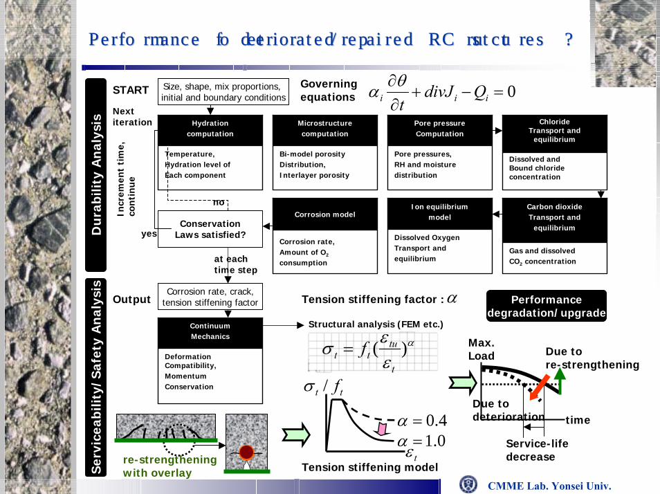
Performance of deteriorated/repaired RC structures ?Performance of deteriorated/repaired RC structures ?
0=−+∂∂
iii QdivJtθα
Pore pressureComputation
Governingequations
Size, shape, mix proportions, initial and boundary conditions
START
Temperature,Hydration level ofEach component
ConservationLaws satisfied?
no
yes
Incr
emen
t ti
me,
co
nti
nue
Du
rabi
lity
An
alys
isD
ura
bilit
y A
nal
ysis
Corrosion rate, crack,tension stiffening factorOutput
Ser
vice
abili
ty/S
afet
y A
nal
ysis
Ser
vice
abili
ty/S
afet
y A
nal
ysis
Deformation Compatibility,MomentumConservation
ContinuumMechanics
at each time step
re-strengtheningwith overlay
Nextiteration Hydration
computation
Bi-model porosityDistribution,Interlayer porosity
Microstructurecomputation
Pore pressures,RH and moisturedistribution
ChlorideTransport and
equilibrium
Dissolved andBound chlorideconcentration
Corrosion rate,Amount of O2
consumption
Corrosion model
Dissolved OxygenTransport andequilibrium
Ion equilibriummodel
Gas and dissolvedCO2 concentration
Carbon dioxideTransport and
equilibrium
Tension stiffening factor :α
tε
tt f/σ
Tension stiffening model
Max.Load
time
Service-lifedecrease
Structural analysis (FEM etc.)
Due to deterioration
α
εεσ )(t
tutt f=
4.0=α0.1=α
Due to re-strengthening
Performancedegradation/upgrade

CMME Lab. Yonsei Univ.
Characteristics of concrete fracture and analysisCharacteristics of concrete fracture and analysis
Material instability
Micro cracksMicro cracks Major macro cracksMajor macro crackslocalize
Softening behaviorDecreased load resistant capacity after peakLocalized strain
Softening behaviorDecreased load resistant capacity after peakLocalized strain
Numerical problem in concrete fracture analysis :
Loss of ellipticity of governing equationIll-posed boundary value problem
Numerical problem in concrete fracture analysis :
Loss of ellipticity of governing equationIll-posed boundary value problem
Numerical drawback(Mesh sensitivity)
Numerical drawback(Mesh sensitivity)

CMME Lab. Yonsei Univ.
Structural instability
Sources of NonSources of Non--linearity ; Material, Geometrical, Boundary and Contactlinearity ; Material, Geometrical, Boundary and Contact
Rt3 Rt2 Rt1 R
u
R
ut1 u t2 u t3 u t4 u
Load controlLoad control Displacement controlDisplacement control
λ
u
A
∆λ0
r
r
Circular path
Final solution
Tangential solution from point A
ArcArc--length control methodlength control method
CMME Lab. Yonsei Univ.
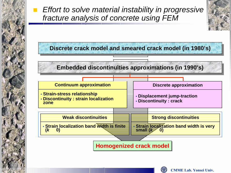
Effort to solve material instability in progressive fracture analysis of concrete using FEM
Embedded discontinuities approximations (in 1990’s)Embedded discontinuities approximations (in 1990’s)
Homogenized crack modelHomogenized crack model
• Strain-stress relationship• Discontinuity : strain localization zone
Continuum approximation
• Displacement jump-traction• Discontinuity : crack
Discrete approximation
• Strain localization band width is finite (k ≫ 0)
Weak discontinuities
• Strain localization band width is very small (k → 0)
Strong discontinuities
Discrete crack model and smeared crack model (in 1980’s)Discrete crack model and smeared crack model (in 1980’s)

CMME Lab. Yonsei Univ.
Effort to solve structural instability in progressive failure of concrete shell structures using FEM
Failure analysis of RC shell structures subjected to various loaFailure analysis of RC shell structures subjected to various loadingsdings
Load Control MethodLoad Control Method : difficulty to obtain post: difficulty to obtain post--peakpeakultimate behavior of RC structuresultimate behavior of RC structures
Displacement Control MethodDisplacement Control Method : difficulty to select a : difficulty to select a representative point for displacement representative point for displacement control in 3D control in 3D
Remove the drawback of load control method
overcome the limitation for displacement control method
Volume Control Volume Control MethodMethod
Layered shell utilizing in-plane constitutive
models of RC

CMME Lab. Yonsei Univ.
Volume Control Method with Pressure NodeVolume Control Method with Pressure Node
Pressure Node : the uniform change of applied pressure on the Pressure Node : the uniform change of applied pressure on the shell shell
element element ((∆∆pp) () (Song and Song and TassoulasTassoulas, IJNME, 1993 ), IJNME, 1993 )

CMME Lab. Yonsei Univ.
Path dependant pseudoPath dependant pseudo--volume control techniquevolume control technique
Pseudo Volume Pseudo Volume ( Song et. al, J. ( Song et. al, J. StrStr. Eng. 2002 ). Eng. 2002 )
PathPath--dependent Volume dependent Volume ( Song et. al, Nuclear Eng. and Design, 2003 )( Song et. al, Nuclear Eng. and Design, 2003 )

CMME Lab. Yonsei Univ.
A
Loading condition checking
∂P∂Vnext
> 0Loading ; Vnext → P1next
Reloading ; Vnext → P3next
∂P∂Vnext
< 0 Unloading ; Vnext → P2next
i+1K
Ki= β is updated according to Loading history
Reloading
Vm = v + ΔVmext
ㅣ(UE)kㅣ
ㅣ(UA)kㅣ< ㅣtoleranceㅣ
(dA) is modified according to comparison experiment displ.
with analysis displ.
P(load)
0 Displacement, UStep i Step i+1
i+1∂P∂U
i+1K =
i∂P∂U
iK =
iK
i+1K
P(load)
0Displacement, U
Experiment
Analysis
(UE)k (UA)k
P(load)
deformed volume, VmVnext
Loading
Unloading
0
Initial volume, V
P1next
P3next
P2next
(dA) is updated according to Loading history
Using tangent Stiffness Matrix Checking (UE)k and (UA)k at each loading steps
Volume increment ΔVmext is controlled according to β
Algorithm for path dependant volume control technique Algorithm for path dependant volume control technique
(ΔVmext)next → ΔVm
ext

CMME Lab. Yonsei Univ.
Pressure Node ← External modified pseudo volume increment ΔVmext
Compute volume change ΔViint using displacement increment Δuk
i
Using Stiffness matrix added Volume-Pressure relation term
Residual volume ΔViR = Δvm
ext - ΔViint
Out of balanced
Element stiffness and nodal vector ; Kei & Fe
i
Assemble and compute RHS vector ; Ki & Fi
Compute residual pressure using residual volume
[Δui, Δpi]T = [Ki]-1[pi, ΔVRI]T
Δpi +1 = Δpi + δpi +1
Δui +1 = Δui + δui +1
Checking convergence
δpi +1 < ㅣtoleranceㅣ
ΔViR < ㅣtoleranceㅣ
At every Gauss point
Calculate strain increment
Δεi = BΔuki
obtain unit vector, n
x’ = x + Δuki
Δuki ← considering loading condition
Using RC constitutive model orthogonal two-way fixed crack model
Calculate stress increment, Di, Δσi
(ΔVmext)next → ΔVm
ext
Structure type
Cylindrical &spherical shell structure Plate-like shell structure
Calculate ΔVmext
No
Yes
ASolution Solution
procedure procedure pathpath--dependant dependant volume control volume control
methodmethod

CMME Lab. Yonsei Univ.
Layered shell elementLayered shell element
Degenerated, isoparametric, serendipity, quadratic shell element with drilling degree of freedom
Geometrical nonlinearity is considered by adopting total Lagrangian formulation
In plane constitutive laws applied to each layer of element consists of RC layers and PL layers

CMME Lab. Yonsei Univ.
Constitutive law for each layerConstitutive law for each layer
Layered RC element
RC layer
Concrete layer
Concrete stress Steel stress
ㅡㅡ Concrete under compression : Concrete under compression : ElastoElasto--plastic fracture model (Maekawa et. al) plastic fracture model (Maekawa et. al) ㅡㅡ Cracked concrete : Smeared fixed crack model Cracked concrete : Smeared fixed crack model ㅡㅡ Concrete under shear : Crack density model (Maekawa and Li) Concrete under shear : Crack density model (Maekawa and Li)
Shear locking + Membrane lockingShear locking + Membrane locking
Reduced integration ( 2 Reduced integration ( 2 ΧΧ 2 Gaussian 2 Gaussian quadraturequadrature ))

CMME Lab. Yonsei Univ.
In-plane constitutive models of cracked concrete
local strain of concrete
shear slip along crack
shea
r stre
ss
trans
ferre
d
aver
age
tens
ile
stre
ss
average tensile strain
mean shear strain
shea
r stre
ss
trans
ferre
dco
mp.
stre
ss
comp. strain
damage zone
crack location
mean stress
crack width
com
p. s
treng
th
redu
ctio
n 1.0
cracked concrete
Tension Stiffening
Shear Transferalong Cracks
Compression Softening
MEAN RESPONSELOCAL RESPONSEMULTI-SYSTEM
mean normal strain
com
p. s
treng
th
redu
ctio
n 1.0

CMME Lab. Yonsei Univ.
Cracking criteria of concrete
Cracking is affected by past loading history.
0.0
0.2
0.4
0.6
0.8
1.0
1.2
0.5 0.6 0.7 0.8 0.9 1.0
F rac tu re pa rame te r (K 0 )
Ra
tio
of
ten
sil
e s
tre
ng
th (
f tt/
f t)
Monotonic loading (Kupfer)
Monotonic loading
Reloading
0.0
0.2
0.4
0.6
0.8
1.0
0.0 0.2 0.4 0.6 0.8 1.0
Norma l i z e d c ompre s s i v e s t r e ngth σ 2 /f ' c
No
rma
liz
ed
te
ns
ile
str
en
gth
Authors'
Niwa
Monotonic loading (Kupfer)
Monotonic loading (Maekawa)
Reloading (Maekawa)
σ1/ ft
< Failure envelope in tension-compression domain > < Normalized tensile strength and fracture parameter >
By taking account influence of continuum fracture in past compression, cracking criterion can be defined in the space of biaxial principal stresses
Compression-tension domain Where, σ1, σ2 : principal stress (σ1 > σ2)
ft : uniaxial tensile strength
Rf : tensile strength reduction factorTension-tension domain

CMME Lab. Yonsei Univ.
Tension stiffening model
Concrete model under tensile stress is unrelated to spacing of cracks, direction of reinforcing bars and reinforcement ration.
Tension stiffening effect is known to increase overall stiffness of RC in tension compared with that of single reinforcing bar.
< Tension stiffening model for deformed bars (c=0.4) and welded meshes (c=0.2) >
Where, σt : average tensile stress, ε : average tensile strain
ft : uniaxial tensile strength, εtu : cracking strain
c : stiffening parameter

CMME Lab. Yonsei Univ.
Steel model
Reinforcing bar model is based on the assumed cosine distribution of bar stress and concrete tension stiffening.
Where, fyt(-fyt) : Bare bar yield strength
fyt1 : Yield strength of bar in concrete
Es : Initial bar stiffness (before yielding)
Eb : Bauchinger’s effect stiffness
Eb = EB (ε0 > 0)
= 1 / (εp / fc+ 1/ Es)
ε0 = εp + fc (1/ Es - 1/ EB)
EB = - Es log10(10 εp)/6

CMME Lab. Yonsei Univ.
MultiMulti--directional smeared crack approachdirectional smeared crack approach
OneOne--way active crack governs the overall nonlinearity as for inway active crack governs the overall nonlinearity as for in--plane cyclic shearplane cyclic shear

CMME Lab. Yonsei Univ.
TwoTwo--way active cracks may control the overall nonlinearity way active cracks may control the overall nonlinearity as for out of plane cyclic actionas for out of plane cyclic action
CMME Lab. Yonsei Univ.
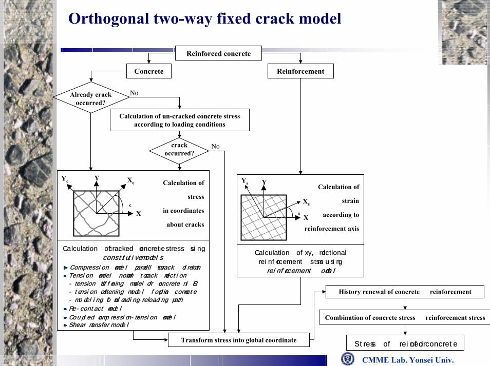
Orthogonal two-way fixed crack model
Reinforced concrete
Already crack occurred?
Calculation of unun--cracked concretecracked concrete stress according to loading conditions
No
Concrete Reinforcement
Calculation of
strain
according to
reinforcement axis
Y
X
Ys
XsΘs
Calculation of x, y directional
reinforcement stress using
reinforcement modelreinforcement model
History renewal of concrete & reinforcement
Combination of concrete stress & reinforcement stress
Stress of reinforced concreteTransform stress into global coordinate
crack occurred?
Y
X
Yc Xc
Θc
Calculation of
stress
in coordinates
about cracks
Calculation of cracked concretecracked concrete stress using
constitutiveconstitutive models models
Compression model parallel to crack directionCompression model parallel to crack direction
Tension model normal to crack directionTension model normal to crack direction
-- tension stiffening model for concrete in RCtension stiffening model for concrete in RC
-- tension softening model for plain concretetension softening model for plain concrete
-- modeling of unloadingmodeling of unloading--reloading pathreloading path
ReRe--contact modelcontact model
Coupled compressionCoupled compression--tension modeltension modelShear transfer modelShear transfer model
No

CMME Lab. Yonsei Univ.
ECC as durable overlays and repair layers
Engineered Cementitious Composites (ECC)V.C. Li et al. 1992~V.C. Li et al. 1992~
cementitious matrix + short random fibersconscious micromechanics-based design of material composition … Performance Driven Design Approach
high performance with low fiber content (~2%)
CMME Lab. Yonsei Univ.
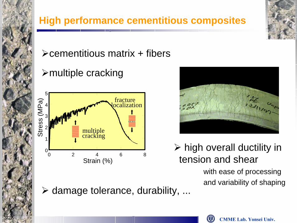
High performance cementitious composites
cementitious matrix + fibers
multiple cracking
high overall ductility intension and shear
with ease of processing and variability of shaping
0
1
2
3
4
5
0 2 4 6 8Strain (%)
Stre
ss (M
Pa)
multiple cracking
fracture localization
damage tolerance, durability, ...
3/28

CMME Lab. Yonsei Univ.
Characteristic of ECC behavior
Strain hardening
Multiple cracking
0
1
2
3
4
5
0 2 4 6 8Strain (%)
Stre
ss (M
Pa)
multiple cracking
fracture localizationmechanical properties:
- high tensile strain capacity (~5%)- small crack width O(10~100 µm)
Localized failure

CMME Lab. Yonsei Univ.
33--d homogenized crack modeld homogenized crack model
3-D formulation of homogenized crack model
• Mixture rule (R.E.V)j
ji
i µµ σσσ += jj
ii µµ εεε +=
1=+ ji µµ
jxy
ixyxy τττ ==
jyz
iyzyz τττ ==
jxx
ixxxx εεε ==
jzz
izzzz εεε ==
jzx
izxzx γγγ ==
jyy
iyyyy σσσ ==
Tzxy ggg },,{=g gKσδ j ][][ =
=
010000001000000010
][δ
=
333231
232221
131211
][KKKKKKKKK
K
==
2
1
000000
][][
S
S
Ne
KK
KKK
• Equilibrium & compatibility
• Velocity discontinuity at crack surface
crackwithconcrete
crackconcrete
jj
ii
:,
:,:,
εσ
εσεσ
Y
XZ
y
z x
B
H
W
t
Representative elementary volume(REV)
CMME Lab. Yonsei Univ.
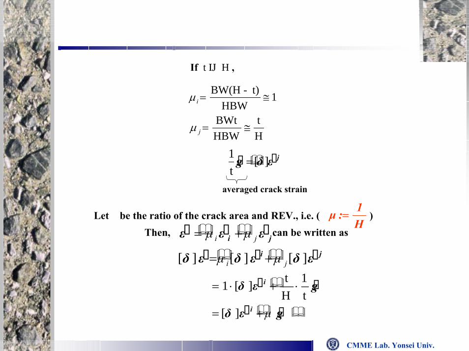
If t ≪ H ,
1HBW
t)-BW(H≅=iµ
Ht
HBWBWt
≅=jµ
jεδg ][t1
=
averaged crack strain
H1:µ =
Then, can be written asji εεε ji µµ +=Let μ be the ratio of the crack area and REV., i.e. ( )
ji εδεδεδ ][][][ ji µµ +=
gεδ
gεδ
i
i
µ+=
⋅+⋅=
][t1
Ht][1

CMME Lab. Yonsei Univ.
• Structural relationshipii εDσ ][=
gεδεδ i µ+≈ ][][
jj
ii µµ σσσ +=
gBεAεδ i ][][][ +=
−−−−−−
−−−−−−
−−−−−−
=
3
56
3
33
3
54
3
53
3
52
3
51
2
46
2
45
2
22
2
43
2
42
2
41
1
26
1
25
1
24
1
23
1
11
1
21
][
CD
CK
CD
CD
CD
CD
CD
CD
CK
CD
CD
CD
CD
CD
CD
CD
CK
CD
µ
µ
µ
A
++
++
++
=
0
0
0
][
3
5432
3
5231
2
4523
2
4221
1
2513
1
2412
CDK
CDK
CDK
CDK
CDK
CDK
µµ
µµ
µµ
B
µ11
221KDC +=
µ22
442KDC +=
µ33
553KDC +=

CMME Lab. Yonsei Univ.
• Structural relationship of (tensile) crack
gεδεδ i µ+= ][][
εSε 1i ][= εSεδ i ][][ =or
gεSεδ µ+= ][][i.e ,
εSδg )][][( −=∴ µ
ε)][]([1 Sδg −=µ
)][]([1][ SδS2 −=µ
Let
εSg 2 ][=then
CMME Lab. Yonsei Univ.
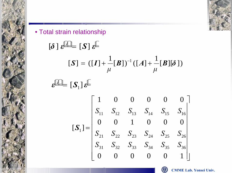
• Total strain relationship
εSεδ i ][][ =
)][][1][()][1][(][ 1 δBABISµµ
++= −
εSε i ][ 1=
=
100000
000100
000001
][
363534333231
262524232221
161514131211
1
SSSSSSSSSSSS
SSSSSS
S

CMME Lab. Yonsei Univ.
• Homogenized constitutive equationjσσσ i
ii µµ +=iσ≈
εSD ][][ 1=εDσ eq ][= ][][][ 1SDDeq =
RemarkCrack width, t, is removed in the final constitutive equation only expressed with μ . This is a solution for the mesh sensitivity problem without the introduction of additional length scale such as a characteristic length.→ Regularization of the continuum model
CMME Lab. Yonsei Univ.
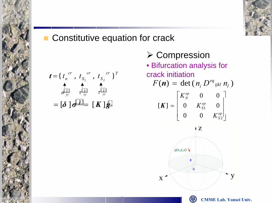
Constitutive equation for crack
Compression
x
p(x,y,z)
yθ
φ
• Bifurcation analysis for crack initiation
)(det)( lijkleq
i nDnF =n
=epS
epS
epN
KK
K
2
1
000000
][K
TcrS
crS
crn ttt },,{
21=t
jyzτj
xyτjyyσ
gKσδ j ][][ ==

CMME Lab. Yonsei Univ.
Failure criteria and softening curve (compression)Failure criteria and softening curve (compression)
Drucker-Prager type0),(21 =−+= pkJIF εσα
Hardening and softening function1) Song and Na (1997)
peeek epp ασσσσσ β
23]1)[(),( 00 −−−++= −
∞
2) Song et al (2003), Farahat et al.(1995) 2])[(
0)( ξβ γ −−=PWp ekWk
3) Barcelona model
k(εp) (J. Lubliner, 1996))]2exp()exp()1[()( 0
pNN
pNNN
p babafk εεε −−−+=
k(Wp) (Modified Barcelona Model, MBM)
)]2exp()exp()1[()( 0p
NNp
NNNp WbaWbafWk −−−+=

CMME Lab. Yonsei Univ.
Failure criteria and softening function (tension)Failure criteria and softening function (tension)
Failure criterial (Gopalaratnam and Shah, 1985))(1 ⋅−= kF σ
Hardening and softening function1) Gopalaratnam and Shah (1985)
)()(λκt
t eftk −=
2) Song et al. (2003)
)()( )( ληκ pyg
tpy efgk −=
3) Barcelona model(J. Lubliner, 1996))( pk ε
)]2exp()exp()1[()( 0p
ttp
tttp babafk εεε −−−+=
(MBM))( pygk
)]2exp()exp()1[()( ''0
pytt
pyttt
py gbagbafgk −−−+=
CMME Lab. Yonsei Univ.
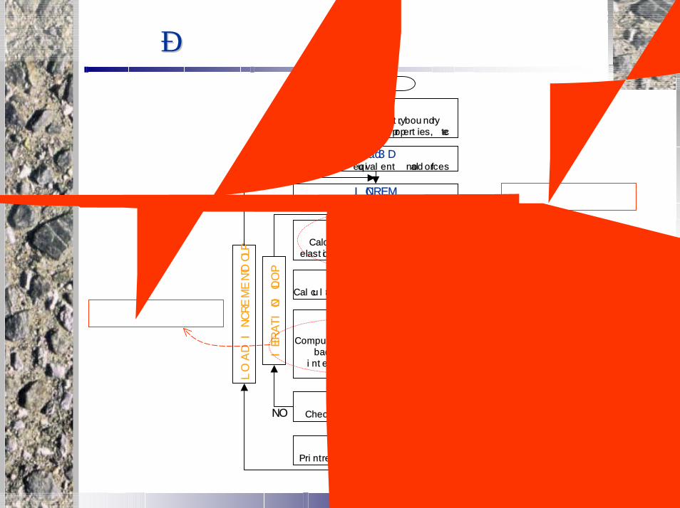
유한유한 요소요소 해석해석 흐름도흐름도Start
INPUTInput data-geometry, boundry
condition, material properties, etc
Load3DEvaluates equivalent nodal forces
INCREMIncrements applied loads
STIF3DCalculate element stiffness for
elastic and elasto-plastic behavior
REACTCalculate displacement and reactions
RESID3BCompute residual stress,
backward Euler integration scheme
CONVERCheck if solution has converged
OUTERSPrint results for this load increment
End
LO
AD
IN
CREM
EN
T L
OO
P
ITERATIO
N L
OO
P
NO
YES
INVAREvaluates invariant stress
YLD3D and FLOWPTDetermine flow vector, a,d, etc
연화함수 변경
손상함수 도입

CMME Lab. Yonsei Univ.
Hardening and softening curve for concrete and ECC (tension)Hardening and softening curve for concrete and ECC (tension)
J. Lubliner (1996))]2exp()exp()1[()( ''
0pytt
pyttt
py gbagbafgk −−−+=
1>ta1<ta Concrete ①
ECC ②
0
0.5
1
1.5
2a°ªÀÇ º¯È-
1.8
0.012
a5 g( )
a4 g( )
a3 g( )
a2 g( )
a1 g( )
a05 g( )
a01 g( )
1.50 g
(0.1~5 )
①
②

CMME Lab. Yonsei Univ.
Result for 2% polyetylane fiber contained ECC
0
0.5
1
1.5
2
2.5
3
3.5
4
4.5
5
0 0.02 0.04 0.06 0.08 0.1 0.12
Strain
Stress (
MPa)
experiment (Li, V. C., 1994)
ECC analysis (a5 b20)
concrete analysis (a0.1 b20)
①
②
⇒ at = 0.1 : Concrete①
⇒ at = 5 : ECC②

CMME Lab. Yonsei Univ.
polyetylane fiber : 0.75% , 1% , 1.25%Experimental result ((TetsushiTetsushi Kanda, 1998)Kanda, 1998)
0
0.5
1
1.5
2
2.5
3
0 0.02 0.04 0.06 0.08 0.1 0.12Strain
Stress
(M
Pa)
experiment (vf 0.75)
experiment (vf 1.0)
experiment (vf 1.25)
Increased at
Decreased bt

CMME Lab. Yonsei Univ.
0.75% ECC
0
0.5
1
1.5
2
2.5
3
0 0.01 0.02 0.03 0.04 0.05 0.06 0.07 0.08
Strain
Stress (
MPa)
experiment (Tetsushi Kanda, 1998)
analysis (a4 b50)

CMME Lab. Yonsei Univ.
1% ECC
0
0.5
1
1.5
2
2.5
3
0 0.02 0.04 0.06 0.08 0.1 0.12
Strain
Stress (
MPa)
experiment (Tetsushi Kanda, 1998)
analysis (a4 b25)

CMME Lab. Yonsei Univ.
1.25% ECC
0
0.5
1
1.5
2
2.5
3
0 0.02 0.04 0.06 0.08 0.1
Strain
Stress (
MPa)
experiment (Tetsushi Kanda,1998)analysis (a5 b25)

CMME Lab. Yonsei Univ.
Mesh sensitivity check on softening behavior
250
200
150
100
50
0
Axi
al S
tress
(kg/
cm2 )
0 .070.060.050.040.030.020.010.00
Disp lacement (mm)
Element 144 Element 300 Element 468

CMME Lab. Yonsei Univ.
Comparison with experimental result
0
0.5
1
1.5
2
2.5
3
3.5
4
0 0.01 0.02 0.03 0.04
Displacement (mm)
Stress
(MPa)
experiment (Gopalaratnam &Shah, 1985)
analysis (HCM,2003)
analysis (HCM+MBM)

CMME Lab. Yonsei Univ.
Mesh sensitivity check for tension
3.5
3.0
2.5
2.0
1.5
1.0
0.5
0.0
Axi
al S
tress
(MPa
)
0.0400.0350.0300.0250.0200.0150.0100.0050.000
Prescribed Displacement (mm)
540 Elements 456 Elements 330 Elements

CMME Lab. Yonsei Univ.
Tension failure with damage
0
0.5
1
1.5
2
2.5
3
3.5
4
0 0.005 0.01 0.015 0.02 0.025 0.03 0.035
Displacement (mm)
Stress (
MPa)
no damage
damage

CMME Lab. Yonsei Univ.
2 . 5 dd/
6
d
P
b
Flexural failure
• 528 elements
• 2977 nodes
0.2 2,680190.5×76.2×38
Specimen (mm)
2.97 1,68028.066.5×12.7
Notch (mm) cν)(GPaEc)(MPaft )/( mGPaKN )/( mGPaKS

CMME Lab. Yonsei Univ.
Results
0
50
100
150
200
250
300
0 0.002 0.004 0.006 0.008 0.01
experiment (Bazant, etal., 1992)
analysis1 (FEM, 1998)
analysis2 (EDM, 2001)
analysis3 (HCM, 2003)
analysis (HCM+MBM)

CMME Lab. Yonsei Univ.
RC panel of simulating RCCV wall subjected to biaxial tensionRC panel of simulating RCCV wall subjected to biaxial tension
Modeling as shell elementModeling as shell element
Specification < HICT and KAERI, 2001 >Compressive strength of concrete (σc) : 41.9MPa
Tensile strength of concrete (σt) : 2.87MPa
Modulus of elasticity of concrete (Ec) : 23828MPa
Yield strength of reinforcement (σy) : 410MPa
Modulus of elasticity of reinforcement (Es) : 205744MPaLayered shell elementLayered shell element

CMME Lab. Yonsei Univ.
FEM MESH and Boundary conditionFEM MESH and Boundary condition
RC panel is discretized
as 10 x 10 mesh

CMME Lab. Yonsei Univ.
StressStress--strain curve of strain curve of rebarsrebars
Hoop direction
Meridional direction
Bottom of RC panelTop of RC panel

CMME Lab. Yonsei Univ.
StressStress--strain curve of strain curve of rebarsrebars
Hoop direction
Meridional direction
Bottom of RC panelTop of RC panel

CMME Lab. Yonsei Univ.
StressStress--strain curve of strain curve of rebarsrebars
Hoop direction
Meridional direction
Bottom of RC panelTop of RC panel
CMME Lab. Yonsei Univ.
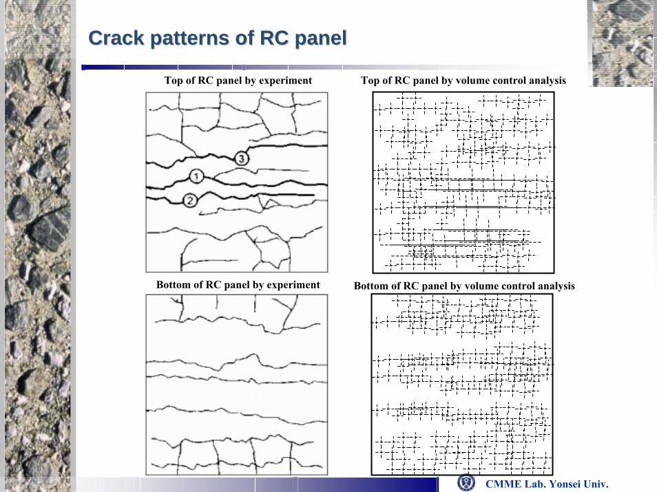
Crack patterns of RC panelCrack patterns of RC panel
Top of RC panel by experiment Top of RC panel by volume control analysis
Bottom of RC panel by experiment Bottom of RC panel by volume control analysis
CMME Lab. Yonsei Univ.
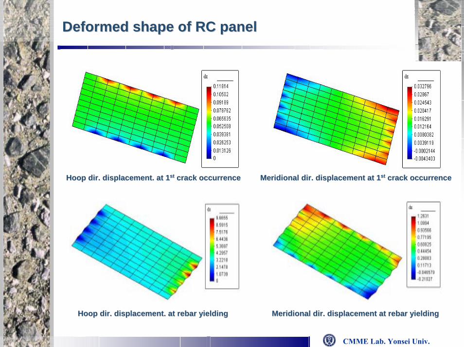
Deformed shape of RC panelDeformed shape of RC panel
Hoop dir. displacement. at 1Hoop dir. displacement. at 1stst crack occurrencecrack occurrence MeridionalMeridional dir. displacement at 1dir. displacement at 1stst crack occurrencecrack occurrence
Hoop dir. displacement. at rebar yieldingHoop dir. displacement. at rebar yielding MeridionalMeridional dir. displacement at rebar yieldingdir. displacement at rebar yielding

CMME Lab. Yonsei Univ.
RCCV subjected to internal pressureRCCV subjected to internal pressure
Specification < SNL, 2001 >
Modeling with or without considering foundationModeling with or without considering foundation
Compressive strength of concrete (σc) : 46.0MPa
Tensile strength of concrete (σt) : 3.45MPa
Modulus of elasticity of concrete (Ec) : 33,100MPa
Poisson’s ratio of concrete (νc) : 0.20
Yield strength of reinforcement (σy) : 450.0MPa
Modulus of elasticity of reinforcement (Es) : 214,000MPa
Poisson’s ratio of reinforcement (νs) : 0.30
Layered shell elementLayered shell element

CMME Lab. Yonsei Univ.
Global behaviorsGlobal behaviors
Radial displacement Radial displacement –– Pressure relationship at midPressure relationship at mid--heightheight
Vertical displacement Vertical displacement –– Pressure relationship at springPressure relationship at spring--lineline

CMME Lab. Yonsei Univ.
Crack patterns of RCCV Crack patterns of RCCV
1.0Pd (0.31MPa)
2.0Pd (0.62MPa)
3.0Pd (0.93MPa)
CMME Lab. Yonsei Univ.
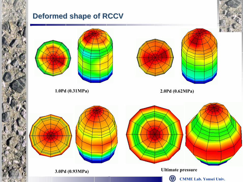
Deformed shape of RCCVDeformed shape of RCCV
1.0Pd (0.31MPa) 2.0Pd (0.62MPa)
Ultimate pressure3.0Pd (0.93MPa)

CMME Lab. Yonsei Univ.
RC tank subjected to reversed cyclic loadingRC tank subjected to reversed cyclic loading
< Harada et al., 2001 >Compressive strength of concrete (σc) : 28.0MPa
Tensile strength of concrete (σt) : 2.20MPa
Modulus of elasticity of concrete (Ec) : 22,600MPa
Yield strength of reinforcement (σy) : 384.0MPa
Modulus of elasticity of reinforcement (Es) : 183,000MPa
Specification
Layered shell elementLayered shell elementModeling as shell elementModeling as shell element

CMME Lab. Yonsei Univ.
Relative horizontal displacement Relative horizontal displacement -- load curveload curve
Comparison experiment result with Comparison experiment result with pathpath--dependant volume control resultdependant volume control result
Comparison pathComparison path--dependant volume dependant volume control result with precontrol result with pre--test analysis resulttest analysis result

CMME Lab. Yonsei Univ.
Crack status of RC tankCrack status of RC tank
Multi-directional cracks occurrence due to reversed cyclic loading
Crack status of RC tank by experimentCrack status of RC tank by experiment
Crack status of RC tank by volume control analysisCrack status of RC tank by volume control analysis
CMME Lab. Yonsei Univ.
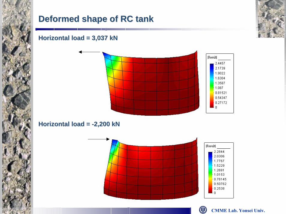
Deformed shape of RC tankDeformed shape of RC tank
Horizontal load = 3,037 Horizontal load = 3,037 kNkN
Horizontal load = Horizontal load = --2,200 2,200 kNkN

CMME Lab. Yonsei Univ.
RC slab subjected to outRC slab subjected to out--of plane cyclic loadingof plane cyclic loading
Specification < Irawan, 2001 >Compressive strength of concrete (σc) : 37.0MPa
Tensile strength of concrete (σt) : 3.70MPa
Yield strength of reinforcement (σy) : 380.0MPa
Modulus of elasticity of reinforcement (Es) : 206,000MPa
CMME Lab. Yonsei Univ.
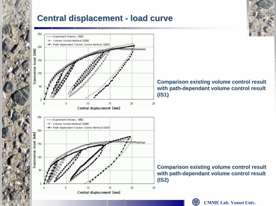
Central displacement Central displacement -- load curveload curve
Comparison existing volume control result Comparison existing volume control result with pathwith path--dependant volume control result dependant volume control result (IS1)(IS1)
Comparison existing volume control result Comparison existing volume control result with pathwith path--dependant volume control result dependant volume control result (IS2)(IS2)

CMME Lab. Yonsei Univ.
Analysis result according to number of layered shell elementAnalysis result according to number of layered shell element
Analysis result according to number of layered shell elementAnalysis result according to number of layered shell element

CMME Lab. Yonsei Univ.
Crack status of RC slabCrack status of RC slab
Specimen IS1 : vertical load = 193 Specimen IS1 : vertical load = 193 kNkN
Specimen IS2 : vertical load = 193 Specimen IS2 : vertical load = 193 kNkN

CMME Lab. Yonsei Univ.
Deformed shape of RC slabDeformed shape of RC slab
Specimen IS1 : vertical load = 178 Specimen IS1 : vertical load = 178 kNkN
Isotropic reinforcement arrangement Isotropic reinforcement arrangement
Stiffness of IS1 > Stiffness of IS2Stiffness of IS1 > Stiffness of IS2Due to reinforcement arrangement
Specimen IS2 : vertical load = 144 Specimen IS2 : vertical load = 144 kNkNDue to reinforcement arrangement
Anisotropic reinforcement arrangement Anisotropic reinforcement arrangement
CMME Lab. Yonsei Univ.
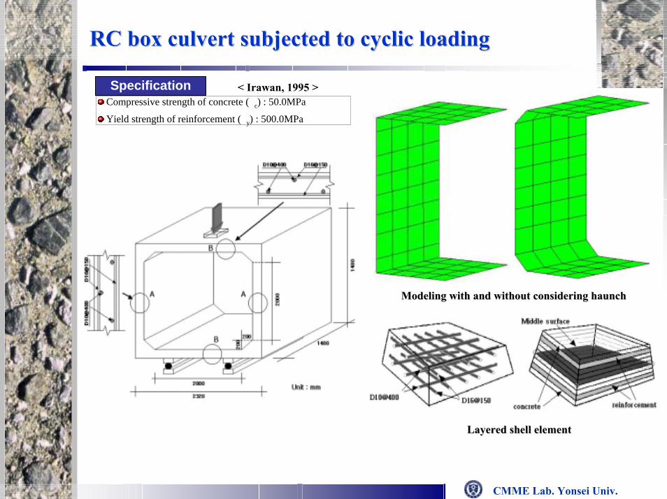
RC box culvert subjected to cyclic loadingRC box culvert subjected to cyclic loading
Specification < Irawan, 1995 >Compressive strength of concrete (σc) : 50.0MPa
Yield strength of reinforcement (σy) : 500.0MPa
Modeling with and without considering haunchModeling with and without considering haunch
Layered shell elementLayered shell element

CMME Lab. Yonsei Univ.
LoadLoad--deflection curve of RC box culvertdeflection curve of RC box culvert
Static failure load : 48 Static failure load : 48 tonftonf Model of considering without considering haunchModel of considering without considering haunch
Model of considering with haunch Model of considering with haunch is reinforced concrete layeris reinforced concrete layer
Model of considering with haunch Model of considering with haunch is plain concrete layeris plain concrete layer
CMME Lab. Yonsei Univ.
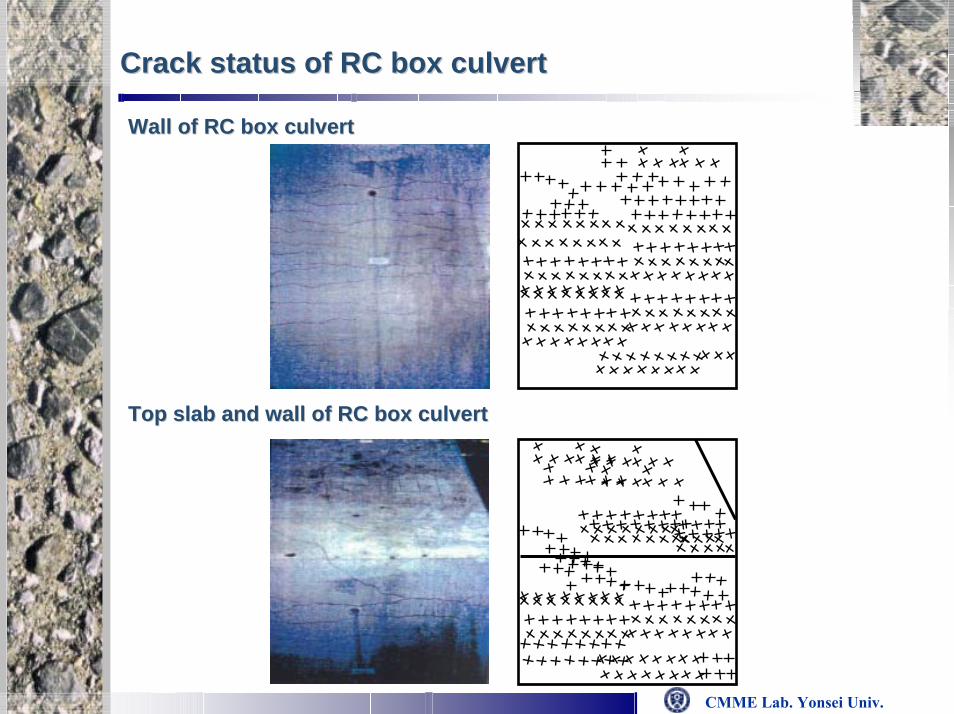
Crack status of RC box culvertCrack status of RC box culvert
Wall of RC box culvertWall of RC box culvert
Top slab and wall of RC box culvertTop slab and wall of RC box culvert

CMME Lab. Yonsei Univ.
Deformed shape of RC box culvertDeformed shape of RC box culvert
Model of considering without haunchModel of considering without haunch
Model of considering with haunch Model of considering with haunch is plain concrete layer
Model of considering with haunch Model of considering with haunch is reinforced concrete layer is plain concrete layeris reinforced concrete layer

CMME Lab. Yonsei Univ.
RC hollow column under lateral loading
Concrete Reinforcement
fcEc
ν
ft
76.5 MPa
31.4 GPa
2.63 MPa
0.21
fy
Es
fu
350 MPa
200 MPa
421 MPa

CMME Lab. Yonsei Univ.
P
Stress-strain curve of concrete and reinforcing steel
(Masukawa et al., 1997)
Modeling as shell element
(a) Steel
(b) Concrete

CMME Lab. Yonsei Univ.
Load-displacement curve
-300
-200
-100
0
100
200
300
-200 -150 -100 -50 0 50 100 150 200
Displacement (mm)
Loa
d (
kN
)
Volume Control Method
Masukawa et al., 1997
Experiment (Masukawa et al., 1997)
Masukawa et al., “Development of RC column members in use of high strength reinforcement”, Proceedings of JCI, Vol. 19, No. 2, pp. 557-564, 1997

CMME Lab. Yonsei Univ.
ContourContour
(a) At final compression (a) At final tension

CMME Lab. Yonsei Univ.
Crack patternsCrack patterns
A B
C D

CMME Lab. Yonsei Univ.
Analysis of 1/4 prestressed concrete containment vessel(PCCV)
Sandia National Laboratories, Albuquerque, New Mexico,2000

CMME Lab. Yonsei Univ.
Tendon layout Unbonded tendon

CMME Lab. Yonsei Univ.
Characteristics of Model Test and AnalysisCharacteristics of Model Test and Analysis
The first model test to satisfy material and design details of design code (ASME Sec. III, Div.2)
• limit state test (LST) and structural failure mechanism test (SFMT)
◆ Large scale model including openings and steel liners
3D finite element modeling including tendons, rebars and openings using DIANA
◆ Pre-test analysis ◆ Post-test analysis
Introduction of volume control technique
1/4 Scale PCCVPCCV model

CMME Lab. Yonsei Univ.
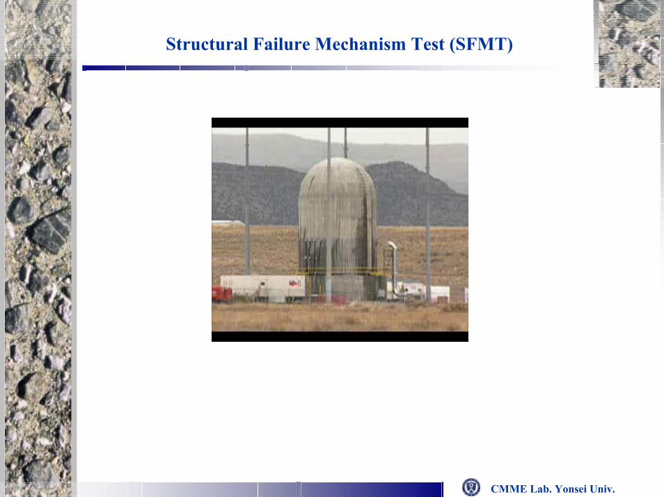
Model Tests (Failure Test due to Internal Pressure)Model Tests (Failure Test due to Internal Pressure)
Limit state test (LST)Limit state test (LST) Structural failure mechanism test (SFMT)Structural failure mechanism test (SFMT)
Pressurized by nitrogen gas
Structural soundness test & leakage test
1.5Pd, 2.0Pd, 2.5Pd and 3.3Pd
(Pd = 0.39 MPa )
Functional failure due to leakage was occurred at 3.3Pd due to tearing of liner
Pressurized by waterStructural failure at 3.6Pd
CMME Lab. Yonsei Univ.
Structural Failure Mechanism Test (SFMT)

CMME Lab. Yonsei Univ.
LST test result LST test result
-Hoop directional deformations govern PCCV behaviors

CMME Lab. Yonsei Univ.
Test result and comparison with the analytical resultsTest result and comparison with the analytical results
Deformation profile at 135˚ section (magnified ×100)Deformation profile at 135˚ section (magnified ×100)
For higher pressure, analysis generally predicts larger deformations than those by the test
The analysis comparably well predicts the global behavior
LST
Analysis
0
2000
4000
6000
8000
10000
12000
14000
16000
18000
0 2000 4000 6000 8000 10000
0.000 MPa
0.389 MPa
0.585 MPa
0.783 MPa
0.978 MPa
1.162 MPa
1.295 MPa
0.000 MPa
0.389 MPa
0.585 MPa
0.783 MPa
0.978 MPa
1.162 MPa
1.295 MPa

CMME Lab. Yonsei Univ.
LST resultsLST results
900Final
3.3
1003.1
difficult to increase pressure3.0
liner strain: 2%evidence of liner tear
1.62.5
no evidence of distress2.0
no leakage0.51.5
ObservationLeakage Rate*Pressure/Pd
* volume change (%) per day (V/Day)**Permissible leakage rate for design pressure:
(pressurized water reactor with steel liner) 0.1% V/Day

CMME Lab. Yonsei Univ.
ComparisonComparison
DeformationsDeformations
Experiment(SNL) Load control
Experiment(SNL) Load control
Radial displ. at midheight Vertical displ. at dome apex
More stable solution is possible with volume control techniqueMore stable solution is possible with volume control technique

CMME Lab. Yonsei Univ.
Rebar stains Rebar stains
Experiment(SNL)
Load control
Experiment(SNL) Load control
Outer rebar hoop strain at dome 45˚Outer rebar hoop strain at midheight

CMME Lab. Yonsei Univ.
Conclusions and future workConclusions and future work
For the failure analysis of RC shell structures using FEM, both
material and structural instability problems can be solved
effectively by the homogenized crack model and the volume
control technique.
In-plane constitutive laws of cracked concrete and modified
Barcelona model can be useful for the modeling of the layered
RC shell element and ECC repaired layers.
Failure analysis or performance evaluation of the deteriorated
RC shell structures repaired with the ECC layers is now under
carried out.

CMME Lab. Yonsei Univ.
Thank you for Thank you for your kind attention!your kind attention!
song@[email protected]