
DRAFT - Washington Savage/Application/Updated Application Ma… · 240´ Diameter x 50´ High Cone...
184
-
Upload
hoangnguyet -
Category
Documents
-
view
220 -
download
0
Transcript of DRAFT - Washington Savage/Application/Updated Application Ma… · 240´ Diameter x 50´ High Cone...


PROJECT ENGINEER
Hagen Engineering Int rnati nal 202 S. Cedar St. Su te B
Owasso, OK 74055
(651) 3 5-46 6
DESIGN ENGINEER
Doug Bayles, P.E.
HEI Job Number: 15-1006
TANK CALCULATIONS
T-Bailey
Tesoro Savage Petroleum Terminal, LLC Tesoro Savage Vancouver Energy
Port of Vancouver, WA
Crude Oil Un-Insulated Storage Tank
240´ Diameter x 50´ High Cone Roof Tank
Preliminary Design Calculat ons
03/03/2015 Preliminary Design Calculations Page 1 of 91, Rev 1
DRAFT

Hagen Engineering International 202 S. Cedar St. Suite B Owasso, OK 74055
Customer: Tesoro Savage Terminal Job Number: 240 x 50 CRT Un-Insulated Date: 03-02-2015 Rev.: 1
Standard Compliant Issues
Shell Shell Course 1 requires impact testing per the standard. Shell Course 2 requires impact testing per the standard.
03/03/2015 Preliminary Design Calculations Page 2 of 91, Rev 1


Hagen Engineering International 202 S. Cedar St. Suite B Owasso, OK 74055
Customer: Tesoro Savage Terminal Job Number: 240 x 50 CRT Un-Insulated Date: 03-02-2015 Rev.: 1
Hagen Engineering International 202 S. Cedar St. Suite B Owasso, OK 74055
Customer: Tesoro Savage Terminal Job Number: 240 x 50 CRT Un-Insulated Date: 03-02-2015 Rev.: 1
Design Data
Tank Diameter .......................................... 240'- 0.0000"
Tank Height ............................................
High Liquid Level ......................................
Low Liquid Level .......................................
50'- 0.0000"
47'- 0.0000"
4'- 0.0000"
(Outside)
Total Capacity .........................................
Working Capacity .......................................
15,765,268 gallons
375,364 barrels
14,357,570 gallons
341,847 barrels
Normal Liquid Level .................................... 46'- 6.0000"
Design Standard......................................... API-650 12th Edition, Add. 1, Annex E
25 °F
25.00 psf Roof Live Load .........................................
150 °F
150 °F
Design Temperature .....................................
Operating Temperature ..................................
Design Metal Temperature ...............................
30.00 psf Ground Snow Load ...................................... 25.20 psf Roof Design Snow Load (0.84 x Ground Snow Load)......
Additional Roof Loads ................................... 0.00 psf
Velocity per ASCE 7-10 Figure 26.5-1A . . . . . . . . . 135 mph
Wind:
Risk Category ....................................... II
C Exposure ...........................................
03/03/2015 Preliminary Design Calculations Page 4 of 91, Rev 1

Hagen Engineering International 202 S. Cedar St. Suite B Owasso, OK 74055
Customer: Tesoro Savage Terminal Job Number: 240 x 50 CRT Un-Insulated Date: 03-02-2015 Rev.: 1
16 Transitional Period (TL) ...........................
0.00 g Vertical Acceleration ..............................
Site Class .........................................
Importance Factor ..................................
Use Group ..........................................
Ss Value ...........................................
S1 Value ...........................................
E
1.00
I
94.00 %
41.20 %
Seismic:
Specific Gravity ....................................... 1.000
Internal Pressure (Design).............................. Atmospheric
(Operating).............................. Atmospheric
Atmospheric (Operating)..............................
External Pressure (Design).............................. 1.00 inches of water
Corrosion Allowance:
Bottom ............................................. 0.1250 in
Annular Ring ....................................... 0.1250 in
Shell Courses 1 - 3 ................................ 0.1875 in
Courses 4 - 4 ................................ 0.1875 in
0.1875 in Courses 5 - 5 ................................
0.0000 in Roof ...............................................
Rafters............................................. 0.0000 in
Cap Plate...........................................
Base Plate..........................................
0.0000 in
0.0000 in
Columns............................................. 0.0000 in
0.0000 in Compression Ring ...................................
03/03/2015 Preliminary Design Calculations Page 5 of 91, Rev 1

Hagen Engineering International 202 S. Cedar St. Suite B Owasso, OK 74055
Customer: Tesoro Savage Terminal Job Number: 240 x 50 CRT Un-Insulated Date: 03-02-2015 Rev.: 1
Summary
Total Weight of Tank: 2,577,353 lbs Total Operating Weight: 134,095,100 lbs Total Testing Weight: 134,095,100 lbs
Primary Bottom – See Bottom of Page for Secondary Bottom and Dead Shell
Bottom with Annular Ring Sloped Up 1.0000 in 120: 0.3750 in (A36) PL (weight: 656,750 lbs)
Annular Ring: 0.5000 in (A36 MOD) PL (weight: 50,680 lbs)
Outside projection = 2.0000 in
Total width: 38.0000 in
Shell
Shell Course 01: 1.1964 in (A573-70) PL x 119.5000 in wide (weight: 366,868 lbs)
Shell Course 1 requires impact testing per the standard.
Shell Course 02: 0.9386 in (A573-70) PL x 119.5000 in wide (weight: 287,815 lbs)
Shell Course 2 requires impact testing per the standard.
Shell Course 03: 0.7400 in (A573-70) PL x 119.5000 in wide (weight: 226,916 lbs)
Shell Course 04: 0.6240 in (A36 MOD) PL x 119.5000 in wide (weight: 191,345 lbs)
Shell Course 05: 0.4000 in (A36 MOD) PL x 118.0000 in wide (weight: 121,118 lbs)
Supported Cone Roof
Roof Slope: 0.7500 in 12 ø: 3.5763° Roof Rise: 7.5000 ft
0.1875 in (A36) PL (weight: 347,093 lbs)
Roof is single lap welded Secondary Bottom 0.2360 in (A36 MOD) PL Outside projection = 2.0000 in Dead Shell or Vertical Spacer Plate Dead Shell: 1.1964 inch (A573-70) PL x 1 ¼” in
03/03/2015 Preliminary Design Calculations Page 6 of 91, Rev 1


Hagen Engineering International 202 S. Cedar St. Suite B Owasso, OK 74055
Customer: Tesoro Savage Terminal Job Number: 240 x 50 CRT Un-Insulated Date: 03-02-2015 Rev.: 1
Bottom Design
Bottom with Annular Ring Sloped Up 1.0000 in 120
Material Grade: A36
in 0.3750 Thickness (tb):
in 0.1250 Corrosion Allowance (CA):
Minimum thickness per 5.4.1 = 0.2360 in
Minimum thickness + corrosion allowance = 0.2360 + 0.1250 = 0.3610 in
Annular Ring
Material Grade: A36 MOD
in 0.5000 Thickness (tb):
in 0.1250 Corrosion Allowance (CA):
Actual outside projection (p) = 2.0000 in
Minimum required outside projection per 5.4.2 = 2.0000 in
Minimum thickness per 5.4.1 = 0.2360 in
td = 1.1963 in tt = 0.9448 in t = 1.1964 in CA = 0.1875 in Sd = 28000.0000 psi St = 30000.0000 psi
Annular ring width: 38.0000 in
sd = ((td - CA)/(t - CA))Sd = ((1.1963 - 0.1875)/(1.1964 - 0.1875)) * 28000.0000 = 27998 psi
st = (tt/t)St = (0.9448 /1.1964) * 30000.0000 = 23690 psi
From Table 5-1, minimum thickness = 0.3438 in
Minimum thickness + corrosion allowance = 0.3438 + 0.1250 = 0.4688 in
Minimum annular ring width inside shell per 5.5.2 = 24.0000 in Fy = 36000.00 psi ϒ = 0.4333 psi/ft Per 5.5.2, width = 2tb √(Fy/(2ϒGH)) = (2 * 0.5000)√(36000.00/(2 * 0.4333 * 1.0000 * 47.0000)) = 29.7287 in
03/03/2015 Preliminary Design Calculations Page 10 of 91, Rev 1

Hagen Engineering International 202 S. Cedar St. Suite B Owasso, OK 74055
Customer: Tesoro Savage Terminal Job Number: 240 x 50 CRT Un-Insulated Date: 03-02-2015 Rev.: 1
Shell Design
Diameter (D) = 240.0000 ft Specific Gravity (G) = 1.000
Shell Height: 9.9583 ft Material Grade: A573-70
Shell Course 01
Product Design Stress per Table 5-2 (Sd) = 28000.0000 psi
H = 47.0000 ft
Hydrostatic Test Stress per Table 5-2 (St) = 30000.0000 psi
Corrosion Allowance (CA): 0.1875 in
For Design per 5.6.4.3 and 5.6.3.2:
tpd = (2.6)(47.0000 - 1.0)(240.0000)(1.0000) 28000.0000 + 0.1875 = 1.2126 in
For Design per 5.6.4.4:
t1d (need not be greater than tpd) = 1.1963 in
+ 0.1875 = 1.1963 in (2.6000)(47.0000)(240.0000)(1.0000) 28000.0000
) √( (47.0000)(1.0000) 28000.0000 1.06 - (0.4630)(240.0000)
47.0000 t1d =
For Hydrotest per 5.6.4.3 and 5.6.3.2:
= 0.9568 in (2.6)(47.0000 - 1.0)(240.0000) 30000.0000
tpt =
For Hydrotest per 5.6.4.4:
t1t = 1.06 - (0.4630)(240.0000) 47.0000 √( 47.0000
30000.0000 ) (2.6000)(47.0000)(240.0000)
30000.0000 = 0.9448 in t1t (need not be greater than tpt) = 0.9448 in
03/03/2015 Preliminary Design Calculations Page 11 of 91, Rev 1

Hagen Engineering International 202 S. Cedar St. Suite B Owasso, OK 74055
Customer: Tesoro Savage Terminal Job Number: 240 x 50 CRT Un-Insulated Date: 03-02-2015 Rev.: 1
(Per 5.6.1.1 - min. t = 0.3750 in) Actual t = 1.1964 in
Use actual thickness for subsequent calculations. Per 5.6.4.2 the required design thickness = 1.1964 inches.
Shell Course 1 requires impact testing per the standard.
03/03/2015 Preliminary Design Calculations Page 12 of 91, Rev 1

Hagen Engineering International 202 S. Cedar St. Suite B Owasso, OK 74055
Customer: Tesoro Savage Terminal Job Number: 240 x 50 CRT Un-Insulated Date: 03-02-2015 Rev.: 1
Shell Height: 9.9583 ft Material Grade: A573-70
Shell Course 02
Product Design Stress per Table 5-2 (Sd) = 28000.0000 psi
H = 37.0417 ft
Hydrostatic Test Stress per Table 5-2 (St) = 30000.0000 psi
Corrosion Allowance (CA): 0.1875 in
For Design per 5.6.4.5:
h1 √(r t1)
= 119.5000
√(1440.0000*1.0089) = 3.1352 hd =
x1 = (0.61)√(1440.0000*0.7510) + (3.8400)(0.1557)(37.0417) = 42.2015 x2 = (12)(0.1557)(37.0417) = 69.1924 x3 = (1.22)√(1440.0000*0.7510) = 40.1198 x = smaller of x1, x2, and x3 = 40.1198
= 0.1557 (√1.3434)(1.3434-1) 1 + (1.3434)^1.5
C = tu = 0.7510 tL = 1.0089 K = tL/tu = 1.0089/0.7510 = 1.3434
For Design per 5.6.4.6:
= 0.7510 in (2.6)(240.0000)(37.0417 - 40.1198/12)(1.0000)
28000.0000 tdx =
t2d = t2a = tdx + CA = 0.7510 + 0.1875 = 0.9385 in
For Hydrotest per 5.6.4.5:
ht = h1
√(r t1) = 119.5000
√(1440.0000*1.1964) = 2.8790
x1 = (0.61)√(1440.0000*0.7032) + (3.8400)(0.2842)(37.0417) = 59.8353 x2 = (12)(0.2842)(37.0417) = 126.3266 x3 = (1.22)√(1440.0000*0.7032) = 38.8216 x = smaller of x1, x2, and x3 = 38.8216
= 0.2842 (√1.7014)(1.7014-1) 1 + (1.7014)^1.5
C = tu = 0.7032 tL = 1.1964 K = tL/tu = 1.1964/0.7032 = 1.7014
For Hydrotest per 5.6.4.6:
ttx = (2.6)(240.0000)(37.0417 - 38.8216/12) 30000.0000 = 0.7032 in
t2t = t2a = tdt = 0.7032 in
03/03/2015 Preliminary Design Calculations Page 13 of 91, Rev 1

Hagen Engineering International 202 S. Cedar St. Suite B Owasso, OK 74055
Customer: Tesoro Savage Terminal Job Number: 240 x 50 CRT Un-Insulated Date: 03-02-2015 Rev.: 1
(Per 5.6.1.1 - min. t = 0.3750 in) Actual t = 0.9386 in
Use actual thickness for subsequent calculations. Per 5.6.4.2 the required design thickness = 0.9386 inches.
Shell Course 2 requires impact testing per the standard.
Shell Height: 9.9583 ft Material Grade: A573-70
Shell Course 03
Product Design Stress per Table 5-2 (Sd) = 28000.0000 psi
H = 27.0833 ft
Hydrostatic Test Stress per Table 5-2 (St) = 30000.0000 psi
Corrosion Allowance (CA): 0.1875 in
x1 = (0.61)√(1440.0000*0.5404) + (3.8400)(0.1742)(27.0833) = 35.1367 x2 = (12)(0.1742)(27.0833) = 56.6275 x3 = (1.22)√(1440.0000*0.5404) = 34.0319 x = smaller of x1, x2, and x3 = 34.0319
= 0.1742 (√1.3900)(1.3900-1) 1 + (1.3900)^1.5
C = tu = 0.5404 tL = 0.7511 K = tL/tu = 0.7511/0.5404 = 1.3900
For Design per 5.6.4.6:
tdx = (2.6)(240.0000)(27.0833 - 34.0319/12)(1.0000) 28000.0000 + 0.1875 = 0.7279 in
x1 = (0.61)√(1440.0000*0.5062) + (3.8400)(0.3300)(27.0833) = 50.7846 x2 = (12)(0.3300)(27.0833) = 107.2339 x3 = (1.22)√(1440.0000*0.5062) = 32.9396 x = smaller of x1, x2, and x3 = 32.9396
= 0.3300 (√1.8541)(1.8541-1) 1 + (1.8541)^1.5
C = tu = 0.5062 tL = 0.9386 K = tL/tu = 0.9386/0.5062 = 1.8541
For Hydrotest per 5.6.4.6:
ttx = (2.6)(240.0000)(27.0833 - 32.9396/12) 30000.0000 = 0.5062 in
(Per 5.6.1.1 - min. t = 0.3750 in) Actual t = 0.7400 in
Use actual thickness for subsequent calculations. Per 5.6.4.2 the required design thickness = 0.7400 inches.
03/03/2015 Preliminary Design Calculations Page 14 of 91, Rev 1

Hagen Engineering International 202 S. Cedar St. Suite B Owasso, OK 74055
Customer: Tesoro Savage Terminal Job Number: 240 x 50 CRT Un-Insulated Date: 03-02-2015 Rev.: 1
Shell Height: 9.9583 ft Material Grade: A36 MOD
Shell Course 04
Product Design Stress per Table 5-2 (Sd) = 23200.0000 psi
H = 17.1250 ft
Hydrostatic Test Stress per Table 5-2 (St) = 24900.0000 psi
Corrosion Allowance (CA): 0.1875 in
x1 = (0.61)√(1440.0000*0.4031) + (3.8400)(0.1666)(17.1250) = 25.6509 x2 = (12)(0.1666)(17.1250) = 34.2314 x3 = (1.22)√(1440.0000*0.4031) = 29.3936 x = smaller of x1, x2, and x3 = 25.6509
= 0.1666 (√1.3706)(1.3706-1) 1 + (1.3706)^1.5
C = tu = 0.4031 tL = 0.5525 K = tL/tu = 0.5525/0.4031 = 1.3706
For Design per 5.6.4.6:
tdx = (2.6)(240.0000)(17.1250 - 25.6509/12)(1.0000) 23200.0000 + 0.1875 = 0.5906 in
x1 = (0.61)√(1440.0000*0.3703) + (3.8400)(0.3690)(17.1250) = 38.3486 x2 = (12)(0.3690)(17.1250) = 75.8194 x3 = (1.22)√(1440.0000*0.3703) = 28.1728 x = smaller of x1, x2, and x3 = 28.1728
= 0.3690 (√1.9983)(1.9983-1) 1 + (1.9983)^1.5
C = tu = 0.3703 tL = 0.7400 K = tL/tu = 0.7400/0.3703 = 1.9983
For Hydrotest per 5.6.4.6:
ttx = (2.6)(240.0000)(17.1250 - 28.1728/12) 24900.0000 = 0.3703 in
(Per 5.6.1.1 - min. t = 0.3750 in) Actual t = 0.6240 in
Use actual thickness for subsequent calculations. Per 5.6.4.2 the required design thickness = 0.6240 inches.
03/03/2015 Preliminary Design Calculations Page 15 of 91, Rev 1

Hagen Engineering International 202 S. Cedar St. Suite B Owasso, OK 74055
Customer: Tesoro Savage Terminal Job Number: 240 x 50 CRT Un-Insulated Date: 03-02-2015 Rev.: 1
Shell Height: 9.8333 ft Material Grade: A36 MOD
Shell Course 05
Product Design Stress per Table 5-2 (Sd) = 23200.0000 psi
H = 7.1667 ft
Hydrostatic Test Stress per Table 5-2 (St) = 24900.0000 psi
Corrosion Allowance (CA): 0.1875 in
x1 = (0.61)√(1440.0000*0.1523) + (3.8400)(0.5399)(7.1667) = 23.8913 x2 = (12)(0.5399)(7.1667) = 46.4333 x3 = (1.22)√(1440.0000*0.1523) = 18.0653 x = smaller of x1, x2, and x3 = 18.0653
= 0.5399 (√2.8667)(2.8667-1) 1 + (2.8667)^1.5
C = tu = 0.1523 tL = 0.4365 K = tL/tu = 0.4365/0.1523 = 2.8667
For Design per 5.6.4.6:
tdx = (2.6)(240.0000)(7.1667 - 18.0653/12)(1.0000) 23200.0000 + 0.1875 = 0.3398 in
x1 = (0.61)√(1440.0000*0.1430) + (3.8400)(0.6946)(7.1667) = 27.8687 x2 = (12)(0.6946)(7.1667) = 59.7318 x3 = (1.22)√(1440.0000*0.1430) = 17.5089 x = smaller of x1, x2, and x3 = 17.5089
= 0.6946 (√4.3626)(4.3626-1) 1 + (4.3626)^1.5
C = tu = 0.1430 tL = 0.6240 K = tL/tu = 0.6240/0.1430 = 4.3626
For Hydrotest per 5.6.4.6:
ttx = (2.6)(240.0000)(7.1667 - 17.5089/12) 24900.0000 = 0.1430 in
(Per 5.6.1.1 - min. t = 0.3750 in) Actual t = 0.4000 in
03/03/2015 Preliminary Design Calculations Page 16 of 91, Rev 1

Hagen Engineering International 202 S. Cedar St. Suite B Owasso, OK 74055
Customer: Tesoro Savage Terminal Job Number: 240 x 50 CRT Un-Insulated Date: 03-02-2015 Rev.: 1
Supported Cone Roof per API-650
Material Grade:
Roof Thickness (tr):
Corrosion Allowance (CA):
A36
0.1875 in
0.0000 in
Roof Slope: 0.7500 in 12 ø: 3.5763° Roof Rise: 7.5000 ft
Live Load (Lv): Snow Load (Sb): Dead Load (DL): Ext. Pressure (Pe):
25.0000 lbf/ft² 25.2000 lbf/ft² 7.6575 lbf/ft² 5.1960 lbf/ft²
Per 5.2.2(e)(1), T = DL + (Lv or Sb) + 0.40Pe = 7.6575 + 25.2000 + (0.40)(5.1960) = 34.9359 lbf/ft²
Per 5.2.2(e)(2), T = DL + 0.4(Lv or Sb) + Pe = 7.6575 + (0.4)(25.2000) + 5.1960 = 22.9335 lbf/ft²
Use greater of (1) or (2), T = 34.9359 lbf/ft²
Tank Diameter (D): 240.0000 ft
Roof is single lap welded
Minimum thickness per 5.10.2.2 =0.1875 in
p = greater of T or U = 34.9359 lbf/ft²
For Unbalanced Snow Load: Su = 1.0 Sb = 1.0 * 25.2000 = 25.2000 lbf/ft²
Per 5.2.2(e)(1), U = DL + Su + 0.40Pe = 7.6575 + 25.2000 + (0.40)(5.1960) = 34.9359 lbf/ft²
Per 5.2.2(e)(2), U = DL + 0.4(Su) + Pe = 7.6575 + (0.4)(25.2000) + 5.1960 = 22.9335 lbf/ft²
Use greater of (1) or (2), U = 34.9359 lbf/ft²
Roof yield strength (Fy) = 36000.0000 psi
Maximum rafter spacing per 5.10.4.4, b = (tr - CA)√(1.5Fy * 144/p)/12 = (0.1875 - 0.0000)√(1.5 * 36000.0000 * 144/34.9359)/12 = 7.3716 ft Not to exceed 7.0000 ft Therefore, b = 7.0000 ft Quantity of rafters (Q) = 160 Actual rafter spacing (R) = π D/Q = π 240.0000/160 = 4.7124 ft
03/03/2015 Preliminary Design Calculations Page 17 of 91, Rev 1

Hagen Engineering International 202 S. Cedar St. Suite B Owasso, OK 74055
Customer: Tesoro Savage Terminal Job Number: 240 x 50 CRT Un-Insulated Date: 03-02-2015 Rev.: 1
Reactions for Inner Rafters
Total Rafter Length: 37.0956 ft Rafter Weight: 12.0000 lbf/ft Roof DL + LL: 34.9359 lbf/ft²
Outer Reaction = (CL)(RL)/2 +(VL)(RL)/3 Inner Reaction = (CL)(RL) + (VL)(RL)/2 - OR
Outer Reaction (lbf)
Outer Spacing (ft)
Inner Reaction (lbf)
Inner Spacing (ft)
Rafter Unsupported Length (ft)
Constant Load
(lbf/ft)
Variable Load
(lbf/ft)
5.1085 0.4581 35.5956 28.0058 162.4653
(28.0058)(35.5956)/2 + (162.4653)(35.5956)/3 = 2426.1270
(28.0058)(35.5956) + (162.4653)(35.5956)/2 - 2426.1270 = 1462.2849
4.9322 0.4581 34.2459 28.0058 156.3047
(28.0058)(34.2459) + (156.3047)(34.2459)/2 - 2263.8061 = 1371.6741
(28.0058)(34.2459)/2 + (156.3047)(34.2459)/3 = 2263.8061
4.8478 33.5999 0.4581 28.0058 153.3565
(28.0058)(33.5999) + (153.3565)(33.5999)/2 - 2188.0846 = 1329.2907
(28.0058)(33.5999)/2 + (153.3565)(33.5999)/3 = 2188.0846
03/03/2015 Preliminary Design Calculations Page 18 of 91, Rev 1

Hagen Engineering International 202 S. Cedar St. Suite B Owasso, OK 74055
Customer: Tesoro Savage Terminal Job Number: 240 x 50 CRT Un-Insulated Date: 03-02-2015 Rev.: 1
Reactions for Intermediate Rafters
Total Rafter Length: 44.5686 ft Rafter Weight: 19.0000 lbf/ft Roof DL + LL: 34.9359 lbf/ft²
Outer Reaction = (CL)(RL)/2 +(VL)(RL)/3 Inner Reaction = (CL)(RL) + (VL)(RL)/2 - OR
Outer Reaction (lbf)
Outer Spacing (ft)
Inner Reaction (lbf)
Inner Spacing (ft)
Rafter Unsupported Length (ft)
Constant Load
(lbf/ft)
Variable Load
(lbf/ft)
6.2393 2.9039 42.5686 120.4520 116.5226
(120.4520)(42.5686)/2 + (116.5226)(42.5686)/3 = 4217.1360
(120.4520)(42.5686) + (116.5226)(42.5686)/2 - 4217.1360 = 3390.4356
03/03/2015 Preliminary Design Calculations Page 19 of 91, Rev 1

Hagen Engineering International 202 S. Cedar St. Suite B Owasso, OK 74055
Customer: Tesoro Savage Terminal Job Number: 240 x 50 CRT Un-Insulated Date: 03-02-2015 Rev.: 1
Reactions for Outer Rafters
Total Rafter Length: 42.6031 ft Rafter Weight: 16.0000 lbf/ft Roof DL + LL: 34.9359 lbf/ft²
Outer Reaction = (CL)(RL)/2 +(VL)(RL)/3 Inner Reaction = (CL)(RL) + (VL)(RL)/2 - OR
Outer Reaction (lbf)
Inner Spacing (ft)
Inner Reaction (lbf)
Outer Spacing (ft)
Rafter Unsupported Length (ft)
Constant Load
(lbf/ft)
Variable Load
(lbf/ft)
3.1300 4.7124 40.3745 125.3484 55.2828
(125.3484)(40.3745)/2 + (55.2828)(40.3745)/3 = 3274.4481
(125.3484)(40.3745) + (55.2828)(40.3745)/2 - 3274.4481 = 2902.4450
3.1106 4.7124 40.8698 124.6703 55.9609
(124.6703)(40.8698) + (55.9609)(40.8698)/2 - 3309.9932 = 2928.8082
(124.6703)(40.8698)/2 + (55.9609)(40.8698)/3 = 3309.9932
3.0961 41.2378 4.7124 124.1663 56.4649
(124.1663)(41.2378) + (56.4649)(41.2378)/2 - 3336.3389 = 2948.2570
(124.1663)(41.2378)/2 + (56.4649)(41.2378)/3 = 3336.3389
3.0866 41.4816 4.7124 123.8325 56.7987
(123.8325)(41.4816) + (56.7987)(41.4816)/2 - 3353.7556 = 2961.0715
(123.8325)(41.4816)/2 + (56.7987)(41.4816)/3 = 3353.7556
3.0818 41.6031 4.7124 123.6662 56.9650
(123.6662)(41.6031) + (56.9650)(41.6031)/2 - 3362.4203 = 2967.4337
(123.6662)(41.6031)/2 + (56.9650)(41.6031)/3 = 3362.4203
03/03/2015 Preliminary Design Calculations Page 20 of 91, Rev 1

Hagen Engineering International 202 S. Cedar St. Suite B Owasso, OK 74055
Customer: Tesoro Savage Terminal Job Number: 240 x 50 CRT Un-Insulated Date: 03-02-2015 Rev.: 1
Loadings and Moments for Intermediate Girders
Total Girder Length: 30.6147 ft Girder Weight: 46.0000 lbf/ft
Load on Column (lbf)
Bending Moment (ft-lb)
Distance from Girder Centerline to Load Centerline (ft)
Load on Girder (lbf) Description
704.14
5389.24
1408.28 Girder
(46.0000)(30.6147)²/8 =
3409.44 13.6335 3409.44 Intermediate Rafter
5706.89 (3409.4356)(30.6147/2 - 13.6335) =
3409.44 10.4224 3409.44 Intermediate Rafter
(3409.4356)(30.6147/2 - 10.4224) = 16654.75
3409.44 7.3508 3409.44 Intermediate Rafter
(3409.4356)(30.6147/2 - 7.3508) = 27127.16
3409.44 4.3739 3409.44 Intermediate Rafter
(3409.4356)(30.6147/2 - 4.3739) = 37276.73
3409.44 1.4520 3409.44 Intermediate Rafter
(3409.4356)(30.6147/2 - 1.4520) = 47238.97
2438.13 12.5446 2438.13 Inner Rafter
(2438.1270)(30.6147/2 - 12.5446) = 6735.92
2292.00 7.3508 2292.00 Inner Rafter
(2292.0031)(30.6147/2 - 7.3508) = 18236.31
2224.03 2.4222 2224.03 Inner Rafter
(2224.0331)(30.6147/2 - 2.4222) = 28657.04
49410.96
193023.00 Total: 24705.48
Total load on Column:
03/03/2015 Preliminary Design Calculations Page 21 of 91, Rev 1

Hagen Engineering International 202 S. Cedar St. Suite B Owasso, OK 74055
Customer: Tesoro Savage Terminal Job Number: 240 x 50 CRT Un-Insulated Date: 03-02-2015 Rev.: 1
Loadings and Moments for Outer Girders
Total Girder Length: 31.2145 ft Girder Weight: 46.0000 lbf/ft
Load on Column (lbf)
Bending Moment (ft-lb)
Distance from Girder Centerline to Load Centerline (ft)
Load on Girder (lbf) Description
717.93
5602.47
1435.86 Girder
(46.0000)(31.2145)²/8 =
2938.10 14.0117 2938.10 Outer Rafter
4687.87 (2938.1015)(31.2145/2 - 14.0117) =
2956.54 10.8527 2956.54 Outer Rafter
(2956.5410)(31.2145/2 - 10.8527) = 14056.88
2970.10 7.7279 2970.10 Outer Rafter
(2970.1007)(31.2145/2 - 7.7279) = 23402.35
2979.01 4.6272 2979.01 Outer Rafter
(2979.0144)(31.2145/2 - 4.6272) = 32709.67
2983.43 1.5408 2983.43 Outer Rafter
(2983.4337)(31.2145/2 - 1.5408) = 41966.21
4236.14 12.4273 4236.14 Intermediate Rafter
(4236.1360)(31.2145/2 - 12.4273) = 13470.64
4236.14 6.1752 4236.14 Intermediate Rafter
(4236.1360)(31.2145/2 - 6.1752) = 39955.52
2118.07 0.0000 4236.14 Intermediate Rafter
(4236.1360)(31.2145/4) = 33057.17
52270.93
208908.78 Total: 26135.46
Total load on Column:
03/03/2015 Preliminary Design Calculations Page 22 of 91, Rev 1

Hagen Engineering International 202 S. Cedar St. Suite B Owasso, OK 74055
Customer: Tesoro Savage Terminal Job Number: 240 x 50 CRT Un-Insulated Date: 03-02-2015 Rev.: 1
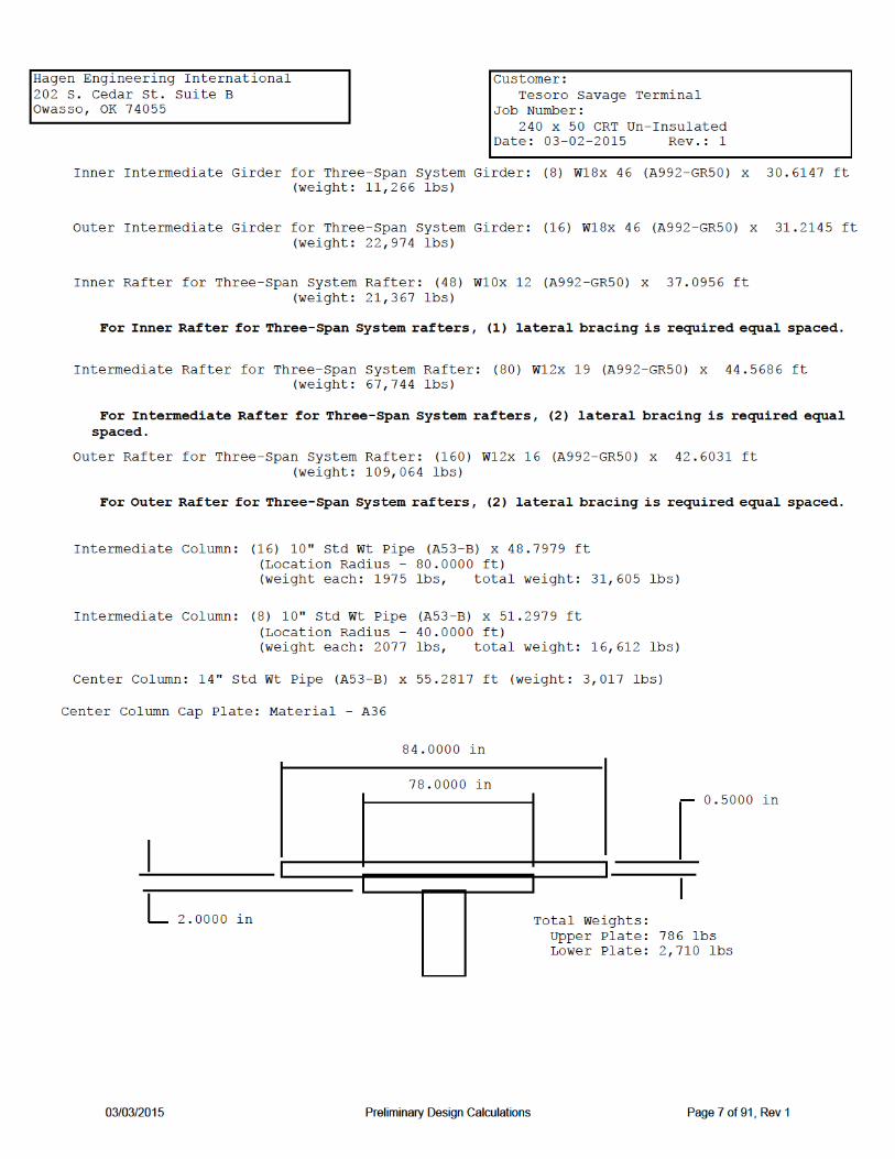
Inner Intermediate Girder for Three-Span System Girder description: W18x 46 Quantity (Q): 8 Material grade: A992-GR50 Yield strength (Fy) = 50000 psi Corrosion allowance (CA) = 0.0000 in
Girder dimensions: Flange width (bf) = 6.0600 in Flange thickness (tf) = 0.6050 in Beam Depth (d) = 18.1000 in Web thickness (tw) = 0.3600 in
Minimum thickness per 5.10.2.4 = 0.1700 in
I = 712.0000 in^4 Sx = 78.8000 in³ Area (A) = 13.5000 in² Radius of Gyration (r) = 7.2500 in
Girder length: Distance from tank centerline to column centerline (Co) = 40.0000 ft Girder length (L) = 2(Co)*sin(360/(2Q) = 2 * (40.0000) * sin(360/(2 * 8)) = 30.6147 ft Girder unsupported length L1 = 6.2393 ft L/r = 12 * 30.6147/7.2500 = 10.3271
Bending Moment due to rafter loads and girder weight: M = 193022.9998 ft-lb
Allowable bending moment:
Per AISC360-10: Allowable Flexure Strength (Mc) = 209739.9815 ft-lb
Per AISC360-10: Allowable Flexure Strength (Mc) = 209739.9815 ft-lb
03/03/2015 Preliminary Design Calculations Page 23 of 91, Rev 1

Hagen Engineering International 202 S. Cedar St. Suite B Owasso, OK 74055
Customer: Tesoro Savage Terminal Job Number: 240 x 50 CRT Un-Insulated Date: 03-02-2015 Rev.: 1
Outer Intermediate Girder for Three-Span System Girder description: W18x 46 Quantity (Q): 16 Material grade: A992-GR50 Yield strength (Fy) = 50000 psi Corrosion allowance (CA) = 0.0000 in
Girder dimensions: Flange width (bf) = 6.0600 in Flange thickness (tf) = 0.6050 in Beam Depth (d) = 18.1000 in Web thickness (tw) = 0.3600 in
Minimum thickness per 5.10.2.4 = 0.1700 in
I = 712.0000 in^4 Sx = 78.8000 in³ Area (A) = 13.5000 in² Radius of Gyration (r) = 7.2500 in
Girder length: Distance from tank centerline to column centerline (Co) = 80.0000 ft Girder length (L) = 2(Co)*sin(360/(2Q) = 2 * (80.0000) * sin(360/(2 * 16)) = 31.2145 ft Girder unsupported length L1 = 3.1300 ft L/r = 12 * 31.2145/7.2500 = 5.1806
Bending Moment due to rafter loads and girder weight: M = 208908.7774 ft-lb
Allowable bending moment:
Per AISC360-10: Allowable Flexure Strength (Mc) = 226297.4052 ft-lb
Per AISC360-10: Allowable Flexure Strength (Mc) = 226297.4052 ft-lb
03/03/2015 Preliminary Design Calculations Page 24 of 91, Rev 1

Hagen Engineering International 202 S. Cedar St. Suite B Owasso, OK 74055
Customer: Tesoro Savage Terminal Job Number: 240 x 50 CRT Un-Insulated Date: 03-02-2015 Rev.: 1
Inner Rafter for Three-Span System for Unbalanced Snow Load
Rafter description: W10x 12 Quantity (Q): 48 Material grade: A992-GR50 Yield strength (Fy) = 50000.0000 psi Corrosion allowance (CA) = 0.0000 in
Rafter dimensions: Flange width (bf) = 3.9600 in Flange thickness (tf) = 0.2100 in Beam Depth (d) = 9.8700 in Web thickness (tw) = 0.1900 in
Minimum thickness per 5.10.2.4 = 0.1700 in
I = 53.8000 in^4 Sx = 10.9000 in³ Area (A) = 3.5400 in² Radius of Gyration (r) = 3.9000 in
Spacing and lengths: Distance from tank centerline to inner edge of rafter (Di) = 3.5000 ft Distance from tank centerline to outer edge of rafter (Do) = 39.0263 ft Inner spacing (Si) = 2πDi/Q = 2π(3.5000/48) = 0.4581 ft Outer spacing (So) = 2πDo/Q = 2π(39.0263/48) = 5.1085 ft Rafter length (L) = (Do - Di)/cos(3.5763) = (39.0263 - 3.5000)/cos(3.5763) = 35.5956 ft
For Inner Rafter for Three-Span System rafters, (1) lateral bracing is required equal spaced.
L1 = L/2 = 35.5956/2 = 17.7978 ft
L/r = 12 * 35.5956/3.9000 = 109.5250
03/03/2015 Preliminary Design Calculations Page 25 of 91, Rev 1

Hagen Engineering International 202 S. Cedar St. Suite B Owasso, OK 74055
Customer: Tesoro Savage Terminal Job Number: 240 x 50 CRT Un-Insulated Date: 03-02-2015 Rev.: 1
For dead load only:
Rafter load (Rw) = 12.0000 lbf/ft Dead load (DL) = 7.6575 lbf/ft² Constant load (CL) = (Si)(DL) + Rw = (0.4581)(7.6575) + 12.0000 = 15.5083 lbf/ft Variable load (VL) = (So - Si)(DL) = (5.1085 - 0.4581)(7.6575) = 35.6103 lbf/ft
Determine location (x) where shear = 0 and calculate moment and stress
(VL/2L)x² + (CL)x - (CLL/2 + VLL/6) = 0 [35.6103/(2*35.5956)x² + (15.5083)x - (15.5083*35.5956/2 + 35.6103*35.5956/6) = 0 (0.5002)x² + (15.5083)x - (487.2752) = 0 therefore x = 19.3472 ft M = (CL)(x)(L - x)/2 + (VL)(x)(L² - x²)/(6L) = (15.5083)(19.3472)(35.5956 - 19.3472)/2 + (35.6103)(19.3472)(35.5956² - 19.3472²)/(6*35.5956) = 5317.4402 ft-lb
Allowable bending moment:
Per AISC360-10: Allowable Flexure Strength (Mc) = 5590.1422 ft-lb
Determine allowable stress:
(VL/2L)x² + (CL)x - (CLL/2 + VLL/6) = 0 [162.4653/(2*35.5956)x² + (28.0058)x - (28.0058*35.5956/2 + 162.4653*35.5956/6) = 0 (2.2821)x² + (28.0058)x - (1462.2849) = 0 therefore x = 19.9104 ft M = (CL)(x)(L - x)/2 + (VL)(x)(L² - x²)/(6L) = (28.0058)(19.9104)(35.5956 - 19.9104)/2 + (162.4653)(19.9104)(35.5956² - 19.9104²)/(6*35.5956) = 17559.4155 ft-lb
Determine location (x) where shear = 0 and calculate moment and stress
Rafter load (Rw) = 12.0000 lbf/ft Dead load + Live load per App. R (DL) = 34.9359 lbf/ft² Constant load (CL) = (Si)(DL) + Rw = (0.4581)(34.9359) + 12.0000 = 28.0058 lbf/ft Variable load (VL) = (So - Si)(DL) = (5.1085 - 0.4581)(34.9359) = 162.4653 lbf/ft
For dead load + live load:
Per 5.10.4.3 the roof provides lateral support to the rafters.
03/03/2015 Preliminary Design Calculations Page 26 of 91, Rev 1
Hagen Engineering International 202 S. Cedar St. Suite B Owasso, OK 74055
Customer: Tesoro Savage Terminal Job Number: 240 x 50 CRT Un-Insulated Date: 03-02-2015 Rev.: 1
Per AISC360-10: Allowable Flexure Strength (Mc) = 31437.1257 ft-lb
Determine reaction at end of rafters: At outer end: Ro = CLL/2 + VLL/3 = (28.0058)(35.5956)/2 + (162.4653)(35.5956)/3 = 2426.1270 lbf Ri = CLL + VLL/2 - Ro = (28.0058)(35.5956) + (162.4653)(35.5956)/2 - 2426.1270 = 1462.2849 lbf
03/03/2015 Preliminary Design Calculations Page 27 of 91, Rev 1

Hagen Engineering International 202 S. Cedar St. Suite B Owasso, OK 74055
Customer: Tesoro Savage Terminal Job Number: 240 x 50 CRT Un-Insulated Date: 03-02-2015 Rev.: 1
Intermediate Rafter for Three-Span System for Unbalanced Snow Load
Rafter description: W12x 19 Quantity (Q): 80 Material grade: A992-GR50 Yield strength (Fy) = 50000.0000 psi Corrosion allowance (CA) = 0.0000 in
Rafter dimensions: Flange width (bf) = 4.0100 in Flange thickness (tf) = 0.3500 in Beam Depth (d) = 12.2000 in Web thickness (tw) = 0.2350 in
Minimum thickness per 5.10.2.4 = 0.1700 in
I = 130.0000 in^4 Sx = 21.3000 in³ Area (A) = 5.5700 in² Radius of Gyration (r) = 4.8200 in
Spacing and lengths: Distance from tank centerline to inner edge of rafter (Di) = 36.9552 ft Distance from tank centerline to outer edge of rafter (Do) = 79.4409 ft Inner spacing (Si) = 2πDi/Q = 2π(36.9552/80) = 3.1416 ft Outer spacing (So) = 2πDo/Q = 2π(79.4409/80) = 6.2393 ft Rafter length (L) = (Do - Di)/cos(3.5763) = (79.4409 - 36.9552)/cos(3.5763) = 42.5686 ft
For Intermediate Rafter for Three-Span System rafters, (2) lateral bracing is required equal spaced.
L1 = L/3 = 42.5686/3 = 14.1895 ft
L/r = 12 * 42.5686/4.8200 = 105.9799
03/03/2015 Preliminary Design Calculations Page 28 of 91, Rev 1

Hagen Engineering International 202 S. Cedar St. Suite B Owasso, OK 74055
Customer: Tesoro Savage Terminal Job Number: 240 x 50 CRT Un-Insulated Date: 03-02-2015 Rev.: 1
For dead load only:
Rafter load (Rw) = 19.0000 lbf/ft Dead load (DL) = 7.6575 lbf/ft² Constant load (CL) = (Si)(DL) + Rw = (3.1416)(7.6575) + 19.0000 = 43.0567 lbf/ft Variable load (VL) = (So - Si)(DL) = (6.2393 - 3.1416)(7.6575) = 23.7205 lbf/ft
Determine location (x) where shear = 0 and calculate moment and stress
(VL/2L)x² + (CL)x - (CLL/2 + VLL/6) = 0 [23.7205/(2*42.5686)x² + (43.0567)x - (43.0567*42.5686/2 + 23.7205*42.5686/6) = 0 (0.2786)x² + (43.0567)x - (1084.7237) = 0 therefore x = 22.0475 ft M = (CL)(x)(L - x)/2 + (VL)(x)(L² - x²)/(6L) = (43.0567)(22.0475)(42.5686 - 22.0475)/2 + (23.7205)(22.0475)(42.5686² - 22.0475²)/(6*42.5686) = 12455.3535 ft-lb
Allowable bending moment:
Per AISC360-10: Allowable Flexure Strength (Mc) = 17330.4213 ft-lb
Determine allowable stress:
(VL/2L)x² + (CL)x - (CLL/2 + VLL/6) = 0 [108.2202/(2*42.5686)x² + (128.7544)x - (128.7544*42.5686/2 + 108.2202*42.5686/6) = 0 (1.2711)x² + (128.7544)x - (3508.2427) = 0 therefore x = 22.3264 ft M = (CL)(x)(L - x)/2 + (VL)(x)(L² - x²)/(6L) = (128.7544)(22.3264)(42.5686 - 22.3264)/2 + (108.2202)(22.3264)(42.5686² - 22.3264²)/(6*42.5686) = 41520.9970 ft-lb
Determine location (x) where shear = 0 and calculate moment and stress
Rafter load (Rw) = 19.0000 lbf/ft Dead load + Live load per App. R (DL) = 34.9359 lbf/ft² Constant load (CL) = (Si)(DL) + Rw = (3.1416)(34.9359) + 19.0000 = 128.7544 lbf/ft Variable load (VL) = (So - Si)(DL) = (6.2393 - 3.1416)(34.9359) = 108.2202 lbf/ft
For dead load + live load:
Per 5.10.4.3 the roof provides lateral support to the rafters.
03/03/2015 Preliminary Design Calculations Page 29 of 91, Rev 1

Hagen Engineering International 202 S. Cedar St. Suite B Owasso, OK 74055
Customer: Tesoro Savage Terminal Job Number: 240 x 50 CRT Un-Insulated Date: 03-02-2015 Rev.: 1
Per AISC360-10: Allowable Flexure Strength (Mc) = 61626.7465 ft-lb
Determine reaction at end of rafters: At outer end: Ro = CLL/2 + VLL/3 = (128.7544)(42.5686)/2 + (108.2202)(42.5686)/3 = 4276.0396 lbf Ri = CLL + VLL/2 - Ro = (128.7544)(42.5686) + (108.2202)(42.5686)/2 - 4276.0396 = 3508.2427 lbf
03/03/2015 Preliminary Design Calculations Page 30 of 91, Rev 1

Hagen Engineering International 202 S. Cedar St. Suite B Owasso, OK 74055
Customer: Tesoro Savage Terminal Job Number: 240 x 50 CRT Un-Insulated Date: 03-02-2015 Rev.: 1
Outer Rafter for Three-Span System for Unbalanced Snow Load
Rafter description: W12x 16 Quantity (Q): 160 Material grade: A992-GR50 Yield strength (Fy) = 50000.0000 psi Corrosion allowance (CA) = 0.0000 in
Rafter dimensions: Flange width (bf) = 3.9900 in Flange thickness (tf) = 0.2650 in Beam Depth (d) = 12.0000 in Web thickness (tw) = 0.2200 in
Minimum thickness per 5.10.2.4 = 0.1700 in
I = 103.0000 in^4 Sx = 17.1000 in³ Area (A) = 4.7100 in² Radius of Gyration (r) = 4.6700 in
Spacing and lengths: Distance from tank centerline to inner edge of rafter (Di) = 78.4779 ft Distance from tank centerline to outer edge of rafter (Do) = 120.0000 ft Inner spacing (Si) = 2πDi/Q = 2π(78.4779/160) = 3.0818 ft Outer spacing (So) = 2πDo/Q = 2π(120.0000/160) = 4.7124 ft Rafter length (L) = (Do - Di)/cos(3.5763) = (120.0000 - 78.4779)/cos(3.5763) = 41.6031 ft
For Outer Rafter for Three-Span System rafters, (2) lateral bracing is required equal spaced.
L1 = L/3 = 41.6031/3 = 13.8677 ft
L/r = 12 * 41.6031/4.6700 = 106.9030
03/03/2015 Preliminary Design Calculations Page 31 of 91, Rev 1

Hagen Engineering International 202 S. Cedar St. Suite B Owasso, OK 74055
Customer: Tesoro Savage Terminal Job Number: 240 x 50 CRT Un-Insulated Date: 03-02-2015 Rev.: 1
For dead load only:
Rafter load (Rw) = 16.0000 lbf/ft Dead load (DL) = 7.6575 lbf/ft² Constant load (CL) = (Si)(DL) + Rw = (3.0818)(7.6575) + 16.0000 = 39.5991 lbf/ft Variable load (VL) = (So - Si)(DL) = (4.7124 - 3.0818)(7.6575) = 12.4860 lbf/ft
Determine location (x) where shear = 0 and calculate moment and stress
(VL/2L)x² + (CL)x - (CLL/2 + VLL/6) = 0 [12.4860/(2*41.6031)x² + (39.5991)x - (39.5991*41.6031/2 + 12.4860*41.6031/6) = 0 (0.1501)x² + (39.5991)x - (910.2970) = 0 therefore x = 21.2729 ft M = (CL)(x)(L - x)/2 + (VL)(x)(L² - x²)/(6L) = (39.5991)(21.2729)(41.6031 - 21.2729)/2 + (12.4860)(21.2729)(41.6031² - 21.2729²)/(6*41.6031) = 9923.1198 ft-lb
Allowable bending moment:
Per AISC360-10: Allowable Flexure Strength (Mc) = 12405.6104 ft-lb
Determine allowable stress:
(VL/2L)x² + (CL)x - (CLL/2 + VLL/6) = 0 [56.9650/(2*41.6031)x² + (123.6662)x - (123.6662*41.6031/2 + 56.9650*41.6031/6) = 0 (0.6846)x² + (123.6662)x - (2967.4337) = 0 therefore x = 21.4487 ft M = (CL)(x)(L - x)/2 + (VL)(x)(L² - x²)/(6L) = (123.6662)(21.4487)(41.6031 - 21.4487)/2 + (56.9650)(21.4487)(41.6031² - 21.4487²)/(6*41.6031) = 32949.6511 ft-lb
Determine location (x) where shear = 0 and calculate moment and stress
Rafter load (Rw) = 16.0000 lbf/ft Dead load + Live load per App. R (DL) = 34.9359 lbf/ft² Constant load (CL) = (Si)(DL) + Rw = (3.0818)(34.9359) + 16.0000 = 123.6662 lbf/ft Variable load (VL) = (So - Si)(DL) = (4.7124 - 3.0818)(34.9359) = 56.9650 lbf/ft
For dead load + live load:
Per 5.10.4.3 the roof provides lateral support to the rafters.
03/03/2015 Preliminary Design Calculations Page 32 of 91, Rev 1

Hagen Engineering International 202 S. Cedar St. Suite B Owasso, OK 74055
Customer: Tesoro Savage Terminal Job Number: 240 x 50 CRT Un-Insulated Date: 03-02-2015 Rev.: 1
Per AISC360-10: Allowable Flexure Strength (Mc) = 50149.7006 ft-lb
Determine reaction at end of rafters: At outer end: Ro = CLL/2 + VLL/3 = (123.6662)(41.6031)/2 + (56.9650)(41.6031)/3 = 3362.4203 lbf Ri = CLL + VLL/2 - Ro = (123.6662)(41.6031) + (56.9650)(41.6031)/2 - 3362.4203 = 2967.4337 lbf
03/03/2015 Preliminary Design Calculations Page 33 of 91, Rev 1

Hagen Engineering International 202 S. Cedar St. Suite B Owasso, OK 74055
Customer: Tesoro Savage Terminal Job Number: 240 x 50 CRT Un-Insulated Date: 03-02-2015 Rev.: 1
Inner Rafter for Three-Span System
Rafter description: W10x 12 Quantity (Q): 48 Material grade: A992-GR50 Yield strength (Fy) = 50000.0000 psi Corrosion allowance (CA) = 0.0000 in
Rafter dimensions: Flange width (bf) = 3.9600 in Flange thickness (tf) = 0.2100 in Beam Depth (d) = 9.8700 in Web thickness (tw) = 0.1900 in
Minimum thickness per 5.10.2.4 = 0.1700 in
I = 53.8000 in^4 Sx = 10.9000 in³ Area (A) = 3.5400 in² Radius of Gyration (r) = 3.9000 in
Spacing and lengths: Distance from tank centerline to inner edge of rafter (Di) = 3.5000 ft Distance from tank centerline to outer edge of rafter (Do) = 39.0263 ft Inner spacing (Si) = 2πDi/Q = 2π(3.5000/48) = 0.4581 ft Outer spacing (So) = 2πDo/Q = 2π(39.0263/48) = 5.1085 ft Rafter length (L) = (Do - Di)/cos(3.5763) = (39.0263 - 3.5000)/cos(3.5763) = 35.5956 ft
For Inner Rafter for Three-Span System rafters, (1) lateral bracing is required equal spaced.
L1 = L/2 = 35.5956/2 = 17.7978 ft
L/r = 12 * 35.5956/3.9000 = 109.5250
03/03/2015 Preliminary Design Calculations Page 34 of 91, Rev 1

Hagen Engineering International 202 S. Cedar St. Suite B Owasso, OK 74055
Customer: Tesoro Savage Terminal Job Number: 240 x 50 CRT Un-Insulated Date: 03-02-2015 Rev.: 1
For dead load only:
Rafter load (Rw) = 12.0000 lbf/ft Dead load (DL) = 7.6575 lbf/ft² Constant load (CL) = (Si)(DL) + Rw = (0.4581)(7.6575) + 12.0000 = 15.5083 lbf/ft Variable load (VL) = (So - Si)(DL) = (5.1085 - 0.4581)(7.6575) = 35.6103 lbf/ft
Determine location (x) where shear = 0 and calculate moment and stress
(VL/2L)x² + (CL)x - (CLL/2 + VLL/6) = 0 [35.6103/(2*35.5956)x² + (15.5083)x - (15.5083*35.5956/2 + 35.6103*35.5956/6) = 0 (0.5002)x² + (15.5083)x - (487.2752) = 0 therefore x = 19.3472 ft M = (CL)(x)(L - x)/2 + (VL)(x)(L² - x²)/(6L) = (15.5083)(19.3472)(35.5956 - 19.3472)/2 + (35.6103)(19.3472)(35.5956² - 19.3472²)/(6*35.5956) = 5317.4402 ft-lb
Allowable bending moment:
Per AISC360-10: Allowable Flexure Strength (Mc) = 5590.1422 ft-lb
Determine allowable stress:
(VL/2L)x² + (CL)x - (CLL/2 + VLL/6) = 0 [162.4653/(2*35.5956)x² + (28.0058)x - (28.0058*35.5956/2 + 162.4653*35.5956/6) = 0 (2.2821)x² + (28.0058)x - (1462.2849) = 0 therefore x = 19.9104 ft M = (CL)(x)(L - x)/2 + (VL)(x)(L² - x²)/(6L) = (28.0058)(19.9104)(35.5956 - 19.9104)/2 + (162.4653)(19.9104)(35.5956² - 19.9104²)/(6*35.5956) = 17559.4155 ft-lb
Determine location (x) where shear = 0 and calculate moment and stress
Rafter load (Rw) = 12.0000 lbf/ft Dead load + Live load per App. R (DL) = 34.9359 lbf/ft² Constant load (CL) = (Si)(DL) + Rw = (0.4581)(34.9359) + 12.0000 = 28.0058 lbf/ft Variable load (VL) = (So - Si)(DL) = (5.1085 - 0.4581)(34.9359) = 162.4653 lbf/ft
For dead load + live load:
Per 5.10.4.3 the roof provides lateral support to the rafters.
03/03/2015 Preliminary Design Calculations Page 35 of 91, Rev 1

Hagen Engineering International 202 S. Cedar St. Suite B Owasso, OK 74055
Customer: Tesoro Savage Terminal Job Number: 240 x 50 CRT Un-Insulated Date: 03-02-2015 Rev.: 1
Per AISC360-10: Allowable Flexure Strength (Mc) = 31437.1257 ft-lb
Determine reaction at end of rafters: At outer end: Ro = CLL/2 + VLL/3 = (28.0058)(35.5956)/2 + (162.4653)(35.5956)/3 = 2426.1270 lbf Ri = CLL + VLL/2 - Ro = (28.0058)(35.5956) + (162.4653)(35.5956)/2 - 2426.1270 = 1462.2849 lbf
03/03/2015 Preliminary Design Calculations Page 36 of 91, Rev 1

Hagen Engineering International 202 S. Cedar St. Suite B Owasso, OK 74055
Customer: Tesoro Savage Terminal Job Number: 240 x 50 CRT Un-Insulated Date: 03-02-2015 Rev.: 1
Intermediate Rafter for Three-Span System
Rafter description: W12x 19 Quantity (Q): 80 Material grade: A992-GR50 Yield strength (Fy) = 50000.0000 psi Corrosion allowance (CA) = 0.0000 in
Rafter dimensions: Flange width (bf) = 4.0100 in Flange thickness (tf) = 0.3500 in Beam Depth (d) = 12.2000 in Web thickness (tw) = 0.2350 in
Minimum thickness per 5.10.2.4 = 0.1700 in
I = 130.0000 in^4 Sx = 21.3000 in³ Area (A) = 5.5700 in² Radius of Gyration (r) = 4.8200 in
Spacing and lengths: Distance from tank centerline to inner edge of rafter (Di) = 36.9552 ft Distance from tank centerline to outer edge of rafter (Do) = 79.4409 ft Inner spacing (Si) = 2πDi/Q = 2π(36.9552/80) = 3.1416 ft Outer spacing (So) = 2πDo/Q = 2π(79.4409/80) = 6.2393 ft Rafter length (L) = (Do - Di)/cos(3.5763) = (79.4409 - 36.9552)/cos(3.5763) = 42.5686 ft
For Intermediate Rafter for Three-Span System rafters, (2) lateral bracing is required equal spaced.
L1 = L/3 = 42.5686/3 = 14.1895 ft
L/r = 12 * 42.5686/4.8200 = 105.9799
03/03/2015 Preliminary Design Calculations Page 37 of 91, Rev 1

Hagen Engineering International 202 S. Cedar St. Suite B Owasso, OK 74055
Customer: Tesoro Savage Terminal Job Number: 240 x 50 CRT Un-Insulated Date: 03-02-2015 Rev.: 1
For dead load only:
Rafter load (Rw) = 19.0000 lbf/ft Dead load (DL) = 7.6575 lbf/ft² Constant load (CL) = (Si)(DL) + Rw = (3.1416)(7.6575) + 19.0000 = 43.0567 lbf/ft Variable load (VL) = (So - Si)(DL) = (6.2393 - 3.1416)(7.6575) = 23.7205 lbf/ft
Determine location (x) where shear = 0 and calculate moment and stress
(VL/2L)x² + (CL)x - (CLL/2 + VLL/6) = 0 [23.7205/(2*42.5686)x² + (43.0567)x - (43.0567*42.5686/2 + 23.7205*42.5686/6) = 0 (0.2786)x² + (43.0567)x - (1084.7237) = 0 therefore x = 22.0475 ft M = (CL)(x)(L - x)/2 + (VL)(x)(L² - x²)/(6L) = (43.0567)(22.0475)(42.5686 - 22.0475)/2 + (23.7205)(22.0475)(42.5686² - 22.0475²)/(6*42.5686) = 12455.3535 ft-lb
Allowable bending moment:
Per AISC360-10: Allowable Flexure Strength (Mc) = 17330.4213 ft-lb
Determine allowable stress:
(VL/2L)x² + (CL)x - (CLL/2 + VLL/6) = 0 [108.2202/(2*42.5686)x² + (128.7544)x - (128.7544*42.5686/2 + 108.2202*42.5686/6) = 0 (1.2711)x² + (128.7544)x - (3508.2427) = 0 therefore x = 22.3264 ft M = (CL)(x)(L - x)/2 + (VL)(x)(L² - x²)/(6L) = (128.7544)(22.3264)(42.5686 - 22.3264)/2 + (108.2202)(22.3264)(42.5686² - 22.3264²)/(6*42.5686) = 41520.9970 ft-lb
Determine location (x) where shear = 0 and calculate moment and stress
Rafter load (Rw) = 19.0000 lbf/ft Dead load + Live load per App. R (DL) = 34.9359 lbf/ft² Constant load (CL) = (Si)(DL) + Rw = (3.1416)(34.9359) + 19.0000 = 128.7544 lbf/ft Variable load (VL) = (So - Si)(DL) = (6.2393 - 3.1416)(34.9359) = 108.2202 lbf/ft
For dead load + live load:
Per 5.10.4.3 the roof provides lateral support to the rafters.
03/03/2015 Preliminary Design Calculations Page 38 of 91, Rev 1

Hagen Engineering International 202 S. Cedar St. Suite B Owasso, OK 74055
Customer: Tesoro Savage Terminal Job Number: 240 x 50 CRT Un-Insulated Date: 03-02-2015 Rev.: 1
Per AISC360-10: Allowable Flexure Strength (Mc) = 61626.7465 ft-lb
Determine reaction at end of rafters: At outer end: Ro = CLL/2 + VLL/3 = (128.7544)(42.5686)/2 + (108.2202)(42.5686)/3 = 4276.0396 lbf Ri = CLL + VLL/2 - Ro = (128.7544)(42.5686) + (108.2202)(42.5686)/2 - 4276.0396 = 3508.2427 lbf
03/03/2015 Preliminary Design Calculations Page 39 of 91, Rev 1

Hagen Engineering International 202 S. Cedar St. Suite B Owasso, OK 74055
Customer: Tesoro Savage Terminal Job Number: 240 x 50 CRT Un-Insulated Date: 03-02-2015 Rev.: 1
Outer Rafter for Three-Span System
Rafter description: W12x 16 Quantity (Q): 160 Material grade: A992-GR50 Yield strength (Fy) = 50000.0000 psi Corrosion allowance (CA) = 0.0000 in
Rafter dimensions: Flange width (bf) = 3.9900 in Flange thickness (tf) = 0.2650 in Beam Depth (d) = 12.0000 in Web thickness (tw) = 0.2200 in
Minimum thickness per 5.10.2.4 = 0.1700 in
I = 103.0000 in^4 Sx = 17.1000 in³ Area (A) = 4.7100 in² Radius of Gyration (r) = 4.6700 in
Spacing and lengths: Distance from tank centerline to inner edge of rafter (Di) = 78.4779 ft Distance from tank centerline to outer edge of rafter (Do) = 120.0000 ft Inner spacing (Si) = 2πDi/Q = 2π(78.4779/160) = 3.0818 ft Outer spacing (So) = 2πDo/Q = 2π(120.0000/160) = 4.7124 ft Rafter length (L) = (Do - Di)/cos(3.5763) = (120.0000 - 78.4779)/cos(3.5763) = 41.6031 ft
For Outer Rafter for Three-Span System rafters, (2) lateral bracing is required equal spaced.
L1 = L/3 = 41.6031/3 = 13.8677 ft
L/r = 12 * 41.6031/4.6700 = 106.9030
03/03/2015 Preliminary Design Calculations Page 40 of 91, Rev 1

Hagen Engineering International 202 S. Cedar St. Suite B Owasso, OK 74055
Customer: Tesoro Savage Terminal Job Number: 240 x 50 CRT Un-Insulated Date: 03-02-2015 Rev.: 1
For dead load only:
Rafter load (Rw) = 16.0000 lbf/ft Dead load (DL) = 7.6575 lbf/ft² Constant load (CL) = (Si)(DL) + Rw = (3.0818)(7.6575) + 16.0000 = 39.5991 lbf/ft Variable load (VL) = (So - Si)(DL) = (4.7124 - 3.0818)(7.6575) = 12.4860 lbf/ft
Determine location (x) where shear = 0 and calculate moment and stress
(VL/2L)x² + (CL)x - (CLL/2 + VLL/6) = 0 [12.4860/(2*41.6031)x² + (39.5991)x - (39.5991*41.6031/2 + 12.4860*41.6031/6) = 0 (0.1501)x² + (39.5991)x - (910.2970) = 0 therefore x = 21.2729 ft M = (CL)(x)(L - x)/2 + (VL)(x)(L² - x²)/(6L) = (39.5991)(21.2729)(41.6031 - 21.2729)/2 + (12.4860)(21.2729)(41.6031² - 21.2729²)/(6*41.6031) = 9923.1198 ft-lb
Allowable bending moment:
Per AISC360-10: Allowable Flexure Strength (Mc) = 12405.6104 ft-lb
Determine allowable stress:
(VL/2L)x² + (CL)x - (CLL/2 + VLL/6) = 0 [56.9650/(2*41.6031)x² + (123.6662)x - (123.6662*41.6031/2 + 56.9650*41.6031/6) = 0 (0.6846)x² + (123.6662)x - (2967.4337) = 0 therefore x = 21.4487 ft M = (CL)(x)(L - x)/2 + (VL)(x)(L² - x²)/(6L) = (123.6662)(21.4487)(41.6031 - 21.4487)/2 + (56.9650)(21.4487)(41.6031² - 21.4487²)/(6*41.6031) = 32949.6511 ft-lb
Determine location (x) where shear = 0 and calculate moment and stress
Rafter load (Rw) = 16.0000 lbf/ft Dead load + Live load per App. R (DL) = 34.9359 lbf/ft² Constant load (CL) = (Si)(DL) + Rw = (3.0818)(34.9359) + 16.0000 = 123.6662 lbf/ft Variable load (VL) = (So - Si)(DL) = (4.7124 - 3.0818)(34.9359) = 56.9650 lbf/ft
For dead load + live load:
Per 5.10.4.3 the roof provides lateral support to the rafters.
03/03/2015 Preliminary Design Calculations Page 41 of 91, Rev 1
Hagen Engineering International 202 S. Cedar St. Suite B Owasso, OK 74055
Customer: Tesoro Savage Terminal Job Number: 240 x 50 CRT Un-Insulated Date: 03-02-2015 Rev.: 1
Per AISC360-10: Allowable Flexure Strength (Mc) = 50149.7006 ft-lb
Determine reaction at end of rafters: At outer end: Ro = CLL/2 + VLL/3 = (123.6662)(41.6031)/2 + (56.9650)(41.6031)/3 = 3362.4203 lbf Ri = CLL + VLL/2 - Ro = (123.6662)(41.6031) + (56.9650)(41.6031)/2 - 3362.4203 = 2967.4337 lbf
03/03/2015 Preliminary Design Calculations Page 42 of 91, Rev 1

Hagen Engineering International 202 S. Cedar St. Suite B Owasso, OK 74055
Customer: Tesoro Savage Terminal Job Number: 240 x 50 CRT Un-Insulated Date: 03-02-2015 Rev.: 1
ALLOWABLE FLEXURE STRENGTH PER AISC360-10
Inner Intermediate Girder for Three-Span System
Girder description: W18x 46 Quantity (Q): 8 Material grade: Yield strength (Fy) = 50000 psi Corrosion allowance (CA) = 0.0000 in
Girder dimensions: Flange width (bf) = 6.0600 in Flange thickness (tf) = 0.6050 in Beam Depth (d) = 18.1000 in Web thickness (tw) = 0.3600 in
Ix = 712.0000 in^4 Sx = 78.8000 in³ Zx = 90.7000 in³ rx = 7.2500 in Iy = 22.5000 in^4 Sy = 7.4300 in³ Zy = 8.0000 in³ ry = 1.2900 in J = 1.2200 in^4 Cw = 1720.0000 in^6 A = 13.5000 in²
Unsupported Girder length (Lb) = 74.8713 in
Determine allowable stress:
Flange classificati0n (AISC 16.1 B4) b = 3.0300 in b/tf = 5.0083 λp = 0.38√(E/Fy) = 0.38√(28800000.0000/50000.0000) = 9.1200 λr = 1.0√(E/Fy) = 1.0√(28800000.0000/50000.0000) = 24.0000
Flanges are Compact
E = 28800000.0000 psi
03/03/2015 Preliminary Design Calculations Page 43 of 91, Rev 1


Hagen Engineering International 202 S. Cedar St. Suite B Owasso, OK 74055
Customer: Tesoro Savage Terminal Job Number: 240 x 50 CRT Un-Insulated Date: 03-02-2015 Rev.: 1
Lp < Lb ≤ Lr
(F2-2) Mn = Cb Mp - (Mp - 0.7FySx) ( [ 1.0000 4535000.0000 - (4535000.0000 - 0.7 * 50000.0000 * 78.8000)
] [
74.8713 - 54.4896 163.6428 - 54.4896
= 4203189.2296 in-lb (
) ] Lb - Lp = Lr - Lp
)
For dead load + live load: Minimmum Mn = 4203189.2296 in-lb Allowable Flexure Strength = Mc = Mn/Ωb = 4203189.2296/1.67 = 2516879.7782 in-lb = 2516879.7782/12 = 209739.9815 ft-lb
03/03/2015 Preliminary Design Calculations Page 45 of 91, Rev 1

Hagen Engineering International 202 S. Cedar St. Suite B Owasso, OK 74055
Customer: Tesoro Savage Terminal Job Number: 240 x 50 CRT Un-Insulated Date: 03-02-2015 Rev.: 1
ALLOWABLE FLEXURE STRENGTH PER AISC360-10
Outer Intermediate Girder for Three-Span System
Girder description: W18x 46 Quantity (Q): 16 Material grade: Yield strength (Fy) = 50000 psi Corrosion allowance (CA) = 0.0000 in
Girder dimensions: Flange width (bf) = 6.0600 in Flange thickness (tf) = 0.6050 in Beam Depth (d) = 18.1000 in Web thickness (tw) = 0.3600 in
Ix = 712.0000 in^4 Sx = 78.8000 in³ Zx = 90.7000 in³ rx = 7.2500 in Iy = 22.5000 in^4 Sy = 7.4300 in³ Zy = 16.0000 in³ ry = 1.2900 in J = 1.2200 in^4 Cw = 1720.0000 in^6 A = 13.5000 in²
Unsupported Girder length (Lb) = 37.5597 in
Determine allowable stress:
Flange classificati0n (AISC 16.1 B4) b = 3.0300 in b/tf = 5.0083 λp = 0.38√(E/Fy) = 0.38√(28800000.0000/50000.0000) = 9.1200 λr = 1.0√(E/Fy) = 1.0√(28800000.0000/50000.0000) = 24.0000
Flanges are Compact
E = 28800000.0000 psi
03/03/2015 Preliminary Design Calculations Page 46 of 91, Rev 1

Hagen Engineering International 202 S. Cedar St. Suite B Owasso, OK 74055
Customer: Tesoro Savage Terminal Job Number: 240 x 50 CRT Un-Insulated Date: 03-02-2015 Rev.: 1
Web classification (AISC 16.1 B4) h/tw = 46.9167 λp = 3.76√(E/Fy) = 3.76√(28800000.0000/50000.0000) = 90.2400 λr = 5.70√(E/Fy) = 5.70√(28800000.0000/50000.0000) = 136.8000
Webs are Compact
(Per AISC 16.1 F1 for ASD) Ωb = 1.67
Lateral Torsional Buckling: (F2-5) Lp = 1.76ry E = 1.76 * 1.2900 Fy √ 28800000.0000
50000.0000 √ = 54.4896 in
Yielding: (F2-1) Mn = Mp = Fy * Zx = 50000.0000 * 90.7000 = 4535000.0000 in-lb
The limit state of lateral-torsional buckling does not apply per F2.2(a).
For dead load + live load: Minimmum Mn = 4535000.0000 in-lb Allowable Flexure Strength = Mc = Mn/Ωb = 4535000.0000/1.67 = 2715568.8623 in-lb = 2715568.8623/12 = 226297.4052 ft-lb
03/03/2015 Preliminary Design Calculations Page 47 of 91, Rev 1

Hagen Engineering International 202 S. Cedar St. Suite B Owasso, OK 74055
Customer: Tesoro Savage Terminal Job Number: 240 x 50 CRT Un-Insulated Date: 03-02-2015 Rev.: 1
ALLOWABLE FLEXURE STRENGTH PER AISC360-10
Inner Rafter for Three-Span System
Rafter description: W10x 12 Quantity (Q): 48 Material grade: The limit state of lateral-torsional buckling does not apply per F2.2(a). Yield strength (Fy) = 50000.0000 psi Corrosion allowance (CA) = 0.0000 in
Rafter dimensions: Flange width (bf) = 3.9600 in Flange thickness (tf) = 0.2100 in Beam Depth (d) = 9.8700 in Web thickness (tw) = 0.1900 in
Ix = 53.8000 in^4 Sx = 10.9000 in³ Zx = 12.6000 in³ rx = 3.9000 in Iy = 2.1800 in^4 Sy = 1.1000 in³ Zy = 1.7400 in³ ry = 0.7850 in J = 0.0547 in^4 Cw = 50.9000 in^6 A = 3.5400 in²
Unsupported Rafter length (Lb) = 213.5737 in
Determine allowable stress:
Flange classificati0n (AISC 16.1 B4) b = 1.9800 in b/tf = 9.4286 λp = 0.38√(E/Fy) = 0.38√(28800000.0000/50000.0000) = 9.1200 λr = 1.0√(E/Fy) = 1.0√(28800000.0000/50000.0000) = 24.0000
Flanges are Non-Compact
E = 28800000.0000 psi
03/03/2015 Preliminary Design Calculations Page 48 of 91, Rev 1


Hagen Engineering International 202 S. Cedar St. Suite B Owasso, OK 74055
Customer: Tesoro Savage Terminal Job Number: 240 x 50 CRT Un-Insulated Date: 03-02-2015 Rev.: 1
(F2-4) Fcr = √
(
( (
1.0000 * π² * 28800000.0000 213.5737 0.9831
1 + 0.078 0.0547 * 1.0000 10.9000 * 9.6600
213.5737 0.9831 √ (
² ²
= 10277.6560 psi
Lb > Lr (F2-3) Mn = Fcr * Sx = 10277.6560 * 10.9000 = 112026.4500 in-lb ≤ Mp
) )
) ) Cbπ²E Lb ² rts
1 + 0.078 Jc Sxho
Lb ² = rts
Compression Flange Local Buckling: Per F3.2: λ = bf/(2tf) = 3.9600/(2 * 0.2100) = 9.4286 kc = 4/√(h/tw) = 4/√(9.8700/0.1900) = 377245.5090 but not less than 0.35 nor greater than 0.76 therefore, kc = 0.5550 λpf = λp = 9.1200 λrf = λr = 24.0000
(F3-1) Mn = Mp - (Mp - 0.7FySx) ( 630000.0000 - (630000.0000 - 0.7 * 50000.0000 * 10.9000)
9.4286 - 9.1200 9.1200 - 24.0000
= 629346.7742 in-lb (
)
)
λ - λpf = λrf - λpf
03/03/2015 Preliminary Design Calculations Page 50 of 91, Rev 1

Hagen Engineering International 202 S. Cedar St. Suite B Owasso, OK 74055
Customer: Tesoro Savage Terminal Job Number: 240 x 50 CRT Un-Insulated Date: 03-02-2015 Rev.: 1
For dead load only: Minimmum Mn = 112026.4500 in-lb Allowable Flexure Strength = Mc = Mn/Ωb = 112026.4500/1.67 = 67081.7066 in-lb = 67081.7066/12 = 5590.1422 ft-lb
For dead load + live load: Minimmum Mn = 630000.0000 in-lb Allowable Flexure Strength = Mc = Mn/Ωb = 630000.0000/1.67 = 377245.5090 in-lb = 377245.5090/12 = 31437.1257 ft-lb
The limit state of lateral-torsional buckling does not apply per F2.2(a).
Per 5.10.4.3 the roof provides lateral support to the rafters.
03/03/2015 Preliminary Design Calculations Page 51 of 91, Rev 1
Hagen Engineering International 202 S. Cedar St. Suite B Owasso, OK 74055
Customer: Tesoro Savage Terminal Job Number: 240 x 50 CRT Un-Insulated Date: 03-02-2015 Rev.: 1
ALLOWABLE FLEXURE STRENGTH PER AISC360-10
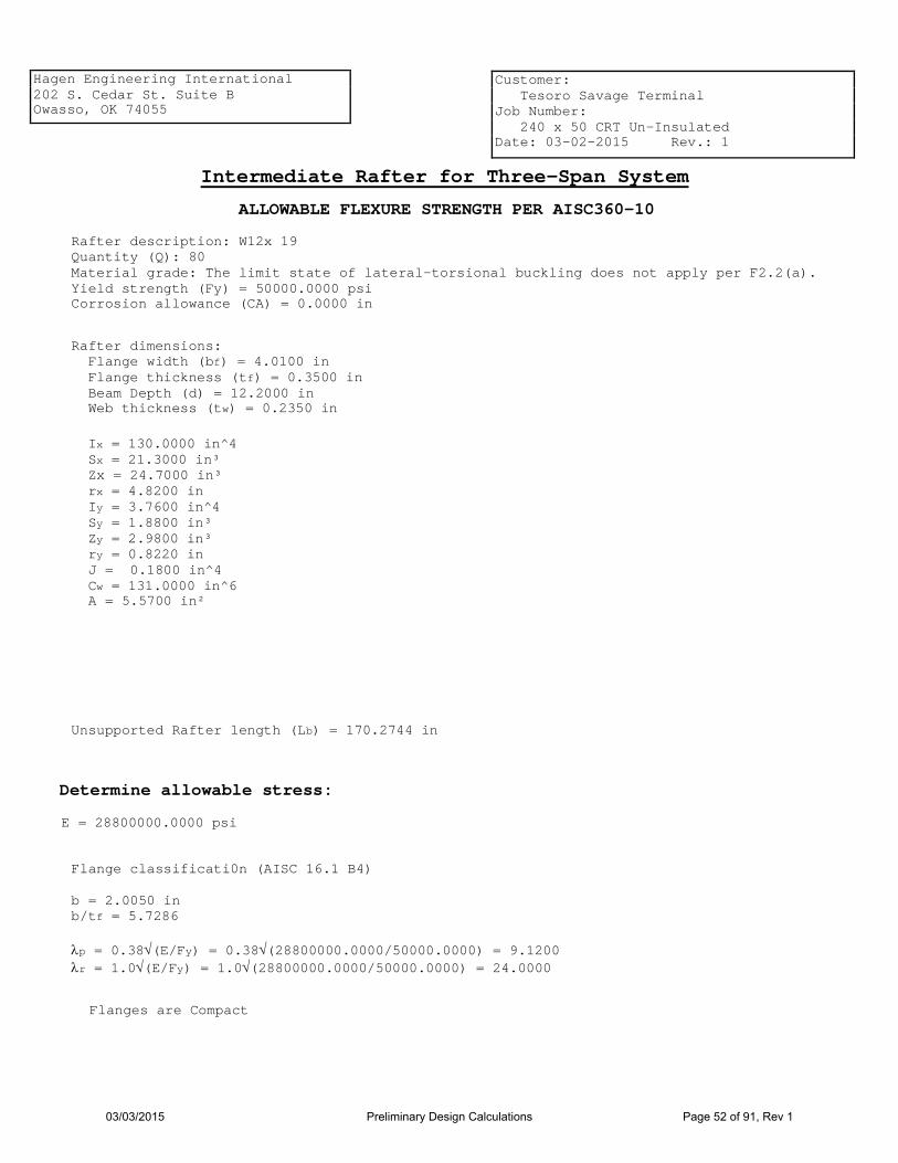
Intermediate Rafter for Three-Span System
Rafter description: W12x 19 Quantity (Q): 80 Material grade: The limit state of lateral-torsional buckling does not apply per F2.2(a). Yield strength (Fy) = 50000.0000 psi Corrosion allowance (CA) = 0.0000 in
Rafter dimensions: Flange width (bf) = 4.0100 in Flange thickness (tf) = 0.3500 in Beam Depth (d) = 12.2000 in Web thickness (tw) = 0.2350 in
Ix = 130.0000 in^4 Sx = 21.3000 in³ Zx = 24.7000 in³ rx = 4.8200 in Iy = 3.7600 in^4 Sy = 1.8800 in³ Zy = 2.9800 in³ ry = 0.8220 in J = 0.1800 in^4 Cw = 131.0000 in^6 A = 5.5700 in²
Unsupported Rafter length (Lb) = 170.2744 in
Determine allowable stress:
Flange classificati0n (AISC 16.1 B4) b = 2.0050 in b/tf = 5.7286 λp = 0.38√(E/Fy) = 0.38√(28800000.0000/50000.0000) = 9.1200 λr = 1.0√(E/Fy) = 1.0√(28800000.0000/50000.0000) = 24.0000
Flanges are Compact
E = 28800000.0000 psi
03/03/2015 Preliminary Design Calculations Page 52 of 91, Rev 1


Hagen Engineering International 202 S. Cedar St. Suite B Owasso, OK 74055
Customer: Tesoro Savage Terminal Job Number: 240 x 50 CRT Un-Insulated Date: 03-02-2015 Rev.: 1
(F2-4) Fcr = √
(
( (
1.0000 * π² * 28800000.0000 170.2744 1.0208
1 + 0.078 0.1800 * 1.0000 21.3000 * 11.8500
170.2744 1.0208 √ (
² ²
= 16305.2415 psi
Lb > Lr (F2-3) Mn = Fcr * Sx = 16305.2415 * 21.3000 = 347301.6433 in-lb ≤ Mp
) )
) ) Cbπ²E Lb ² rts
1 + 0.078 Jc Sxho
Lb ² = rts
For dead load only: Minimmum Mn = 347301.6433 in-lb Allowable Flexure Strength = Mc = Mn/Ωb = 347301.6433/1.67 = 207965.0559 in-lb = 207965.0559/12 = 17330.4213 ft-lb
For dead load + live load: Minimmum Mn = 1235000.0000 in-lb Allowable Flexure Strength = Mc = Mn/Ωb = 1235000.0000/1.67 = 739520.9581 in-lb = 739520.9581/12 = 61626.7465 ft-lb
The limit state of lateral-torsional buckling does not apply per F2.2(a).
Per 5.10.4.3 the roof provides lateral support to the rafters.
03/03/2015 Preliminary Design Calculations Page 54 of 91, Rev 1

Hagen Engineering International 202 S. Cedar St. Suite B Owasso, OK 74055
Customer: Tesoro Savage Terminal Job Number: 240 x 50 CRT Un-Insulated Date: 03-02-2015 Rev.: 1
ALLOWABLE FLEXURE STRENGTH PER AISC360-10
Outer Rafter for Three-Span System
Rafter description: W12x 16 Quantity (Q): 160 Material grade: The limit state of lateral-torsional buckling does not apply per F2.2(a). Yield strength (Fy) = 50000.0000 psi Corrosion allowance (CA) = 0.0000 in
Rafter dimensions: Flange width (bf) = 3.9900 in Flange thickness (tf) = 0.2650 in Beam Depth (d) = 12.0000 in Web thickness (tw) = 0.2200 in
Ix = 103.0000 in^4 Sx = 17.1000 in³ Zx = 20.1000 in³ rx = 4.6700 in Iy = 2.8200 in^4 Sy = 1.4100 in³ Zy = 2.2600 in³ ry = 0.7730 in J = 0.1030 in^4 Cw = 96.9000 in^6 A = 4.7100 in²
Unsupported Rafter length (Lb) = 166.4123 in
Determine allowable stress:
Flange classificati0n (AISC 16.1 B4) b = 1.9950 in b/tf = 7.5283 λp = 0.38√(E/Fy) = 0.38√(28800000.0000/50000.0000) = 9.1200 λr = 1.0√(E/Fy) = 1.0√(28800000.0000/50000.0000) = 24.0000
Flanges are Compact
E = 28800000.0000 psi
03/03/2015 Preliminary Design Calculations Page 55 of 91, Rev 1


Hagen Engineering International 202 S. Cedar St. Suite B Owasso, OK 74055
Customer: Tesoro Savage Terminal Job Number: 240 x 50 CRT Un-Insulated Date: 03-02-2015 Rev.: 1
(F2-4) Fcr = √
(
( (
1.0000 * π² * 28800000.0000 166.4123 0.9832
1 + 0.078 0.1030 * 1.0000 17.1000 * 11.7350
166.4123 0.9832 √ (
² ²
= 14538.5049 psi
Lb > Lr (F2-3) Mn = Fcr * Sx = 14538.5049 * 17.1000 = 248608.4333 in-lb ≤ Mp
) )
) ) Cbπ²E Lb ² rts
1 + 0.078 Jc Sxho
Lb ² = rts
For dead load only: Minimmum Mn = 248608.4333 in-lb Allowable Flexure Strength = Mc = Mn/Ωb = 248608.4333/1.67 = 148867.3253 in-lb = 148867.3253/12 = 12405.6104 ft-lb
For dead load + live load: Minimmum Mn = 1005000.0000 in-lb Allowable Flexure Strength = Mc = Mn/Ωb = 1005000.0000/1.67 = 601796.4072 in-lb = 601796.4072/12 = 50149.7006 ft-lb
The limit state of lateral-torsional buckling does not apply per F2.2(a).
Per 5.10.4.3 the roof provides lateral support to the rafters.
03/03/2015 Preliminary Design Calculations Page 57 of 91, Rev 1

Hagen Engineering International 202 S. Cedar St. Suite B Owasso, OK 74055
Customer: Tesoro Savage Terminal Job Number: 240 x 50 CRT Un-Insulated Date: 03-02-2015 Rev.: 1
Intermediate Column for Supported Cone Roof
(16) Columns located on 80.0000 ft Radius
Column description: 10" Std Wt Pipe Material grade: A53-B Yield strength (Fy) = 35000.0000 psi Corrosion allowance (CA) = 0.0000 in
Outside Diameter (Do) = 10.7500 in Wall thickness (tw) = 0.3650 in Mill tolerance (m) = 12.50%
therefore tw = tw(1 - m) = 0.3650(1 - 0.1250) = 0.3194 in
t = tw = 0.3194 in
Pipe Inside Diameter (Di) = Do - 2t = 10.7500 - 2*0.3194 = 10.1113 in Area (A) = π (Do² - Di²)/4 = π(10.7500² - 10.1113²)/4 = 10.4655 in² Radius of Gyration (r) = √(Do² + Di²)/4 = √(10.7500² + 10.1113²)/4 = 3.6895 in Section Modulus (qs) = 0.098175(Do/^4 - d1^4)/Do = 0.098175((10.7500)^4 - (10.1113)^4)/10.7500 = 26.5046 in³
K = 1.00 Calculate column length: Tank Radius (R1) = 120.0000 ft
Column Location Radius (R2) = 80.0000 ft
Bottom with Annular Ring Sloped Up 1.0000 in 120
Roof Rise (L1) = (R1 - R2)tan(0.0624) = (120.0000 - 80.0000)tan(0.0624) = 2.5000 ft
Bottom Slope (L2) = -(R1)(Rise)/Run = -(120.0000)(1.0000)/120.0000 = -1.0000 ft
Tank vertical height (L3) = 50.0000 ft
Rafter depth (L5) = 12.2000 in Girder depth (L6) = 18.1000 in Therefore, L = (L1 + L2 + L3)12 - L5 - L6 = (2.5000 + -1.0000 + 50.0000)12 - 12.2000 - 18.1000 = 585.5750 in
KL/r = (1.00)(585.5750)/3.6895 = 158.7134
For Outer Intermediate Column, KL/r = 158.7
Calculate column load: P (from girder loads) = 52270.9273 lbf
Modulus of Elasticity at 150.0000° (E): 28800000.0000 psi
03/03/2015 Preliminary Design Calculations Page 58 of 91, Rev 1

Hagen Engineering International 202 S. Cedar St. Suite B Owasso, OK 74055
Customer: Tesoro Savage Terminal Job Number: 240 x 50 CRT Un-Insulated Date: 03-02-2015 Rev.: 1
DETERMINE ALLOWABLE LOAD PER AISC 360-10 E3: Ωc = 1.67 V = 4.71√(E/Fy) = 4.71√[(28800000.0000)/35000.0000] = 135.1086
Fe = π²E (KL/r)²
= π²(28800000.0000) (158.7134)²
= 11284.0454 psi
(E3-3) Fcr = 0.877Fe = 0.877 * 11284.0454 = 9896.1078 psi
(E3.1) Pn = FcrA = 9896.1078 * 10.4655 = 103567.9884 lbf Pc = Pn/ΩC = 103567.9884/1.67 = 62016.7595 lbf
For Outer Intermediate Column, load (52270.93) is less than the allowable load (62016.76).
03/03/2015 Preliminary Design Calculations Page 59 of 91, Rev 1

Hagen Engineering International 202 S. Cedar St. Suite B Owasso, OK 74055
Customer: Tesoro Savage Terminal Job Number: 240 x 50 CRT Un-Insulated Date: 03-02-2015 Rev.: 1
Intermediate Column for Supported Cone Roof
(8) Columns located on 40.0000 ft Radius
Column description: 10" Std Wt Pipe Material grade: A53-B Yield strength (Fy) = 35000.0000 psi Corrosion allowance (CA) = 0.0000 in
Outside Diameter (Do) = 10.7500 in Wall thickness (tw) = 0.3650 in Mill tolerance (m) = 12.50%
therefore tw = tw(1 - m) = 0.3650(1 - 0.1250) = 0.3194 in
t = tw = 0.3194 in
Pipe Inside Diameter (Di) = Do - 2t = 10.7500 - 2*0.3194 = 10.1113 in Area (A) = π (Do² - Di²)/4 = π(10.7500² - 10.1113²)/4 = 10.4655 in² Radius of Gyration (r) = √(Do² + Di²)/4 = √(10.7500² + 10.1113²)/4 = 3.6895 in Section Modulus (qs) = 0.098175(Do/^4 - d1^4)/Do = 0.098175((10.7500)^4 - (10.1113)^4)/10.7500 = 26.5046 in³
K = 1.00 Calculate column length: Tank Radius (R1) = 120.0000 ft
Column Location Radius (R2) = 40.0000 ft
Bottom with Annular Ring Sloped Up 1.0000 in 120
Roof Rise (L1) = (R1 - R2)tan(0.0624) = (120.0000 - 40.0000)tan(0.0624) = 5.0000 ft
Bottom Slope (L2) = -(R1)(Rise)/Run = -(120.0000)(1.0000)/120.0000 = -1.0000 ft
Tank vertical height (L3) = 50.0000 ft
Rafter depth (L5) = 12.2000 in Girder depth (L6) = 18.1000 in Therefore, L = (L1 + L2 + L3)12 - L5 - L6 = (5.0000 + -1.0000 + 50.0000)12 - 12.2000 - 18.1000 = 615.5750 in
KL/r = (1.00)(615.5750)/3.6895 = 166.8446
For Inner Intermediate Column, KL/r = 166.8
Calculate column load: P (from girder loads) = 49410.9574 lbf
Modulus of Elasticity at 150.0000° (E): 28800000.0000 psi
03/03/2015 Preliminary Design Calculations Page 60 of 91, Rev 1

Hagen Engineering International 202 S. Cedar St. Suite B Owasso, OK 74055
Customer: Tesoro Savage Terminal Job Number: 240 x 50 CRT Un-Insulated Date: 03-02-2015 Rev.: 1
DETERMINE ALLOWABLE LOAD PER AISC 360-10 E3: Ωc = 1.67 V = 4.71√(E/Fy) = 4.71√[(28800000.0000)/35000.0000] = 135.1086
Fe = π²E (KL/r)²
= π²(28800000.0000) (166.8446)²
= 10210.9919 psi
(E3-3) Fcr = 0.877Fe = 0.877 * 10210.9919 = 8955.0399 psi
(E3.1) Pn = FcrA = 8955.0399 * 10.4655 = 93719.2162 lbf Pc = Pn/ΩC = 93719.2162/1.67 = 56119.2911 lbf
For Inner Intermediate Column, load (49410.96) is less than the allowable load (56119.29).
03/03/2015 Preliminary Design Calculations Page 61 of 91, Rev 1

Hagen Engineering International 202 S. Cedar St. Suite B Owasso, OK 74055
Customer: Tesoro Savage Terminal Job Number: 240 x 50 CRT Un-Insulated Date: 03-02-2015 Rev.: 1
Center Column for Supported Cone Roof Column description: 14" Std Wt Pipe Material grade: A53-B Yield strength (Fy) = 35000.0000 psi Corrosion allowance (CA) = 0.0000 in
Outside Diameter (Do) = 14.0000 in Wall thickness (tw) = 0.3750 in Mill tolerance (m) = 12.50%
therefore tw = tw(1 - m) = 0.3750(1 - 0.1250) = 0.3281 in
t = tw = 0.3281 in
Pipe Inside Diameter (Di) = Do - 2t = 14.0000 - 2*0.3281 = 13.3438 in Area (A) = π (Do² - Di²)/4 = π(14.0000² - 13.3438²)/4 = 14.0934 in² Radius of Gyration (r) = √(Do² + Di²)/4 = √(14.0000² + 13.3438²)/4 = 4.8351 in Section Modulus (qs) = 0.098175(Do/^4 - d1^4)/Do = 0.098175((14.0000)^4 - (13.3438)^4)/14.0000 = 47.0692 in³
K = 1.00 Calculate column length: Tank Radius (R1) = 120.0000 ft
Cap Radius (R2) = 3.5000 ft
Bottom with Annular Ring Sloped Up 1.0000 in 120
Roof Rise (L1) = (R1 - R2)tan(0.0624) = (120.0000 - 3.5000)tan(0.0624) = 7.2813 ft
Bottom Slope (L2) = -(R1)(Rise)/Run = -(120.0000)(1.0000)/120.0000 = -1.0000 ft
Tank vertical height (L3) = 50.0000 ft
Rafter depth (L5) = 9.8700 in Therefore, L = (L1 + L2 + L3)12 - L5 = (7.2813 + -1.0000 + 50.0000)12 - 9.8700 = 663.3800 in
KL/r = (1.00)(663.3800)/4.8351 = 137.2000
For center column, KL/r = 137.2
03/03/2015 Preliminary Design Calculations Page 62 of 91, Rev 1

Hagen Engineering International 202 S. Cedar St. Suite B Owasso, OK 74055
Customer: Tesoro Savage Terminal Job Number: 240 x 50 CRT Un-Insulated Date: 03-02-2015 Rev.: 1
Calculate column load: Quantity of rafters (Q) = 48 Total load from Reactions for Inner Rafters (Ri) = 66611.9960 lbf Rafter extension on cap (L6) = 6.0000 in Rafter weight (Rw) = 12.0000 lbf Roof dead load + live load (DL) = 34.9359 lbf/ft² Weight of cap plate (Cw) = 3496.2470 lbf P = Ri + QRw(L6/12) + πR2²DL + Cw = 66611.9960 + (48)(12.0000)(6.0000/12) + π(3.5000)²(34.9359) + 3496.2470 = 71740.7340 lbf
Modulus of Elasticity at 150.0000° (E): 28800000.0000 psi
DETERMINE ALLOWABLE LOAD PER AISC 360-10 E3: Ωc = 1.67 V = 4.71√(E/Fy) = 4.71√[(28800000.0000)/35000.0000] = 135.1086
Fe = π²E (KL/r)²
= π²(28800000.0000) (137.2000)²
= 15100.2361 psi
(E3-3) Fcr = 0.877Fe = 0.877 * 15100.2361 = 13242.9071 psi
(E3.1) Pn = FcrA = 13242.9071 * 14.0934 = 186638.2285 lbf Pc = Pn/ΩC = 186638.2285/1.67 = 111759.4183 lbf
Load on center column (71740.73) is less than the allowable load (111759.42).
03/03/2015 Preliminary Design Calculations Page 63 of 91, Rev 1

Hagen Engineering International 202 S. Cedar St. Suite B Owasso, OK 74055
Customer: Tesoro Savage Terminal Job Number: 240 x 50 CRT Un-Insulated Date: 03-02-2015 Rev.: 1
Center Column for Supported Cone Roof (Unbalanced Snow Load)
Column description: 14" Std Wt Pipe Material grade: A53-B Yield strength (Fy) = 35000.0000 psi Corrosion allowance (CA) = 0.0000 in
Cap Radius (R2) = 3.5000 ft
KL/r = (1.00)(663.3800)/4.8351 = 137.2000
03/03/2015 Preliminary Design Calculations Page 64 of 91, Rev 1


Hagen Engineering International 202 S. Cedar St. Suite B Owasso, OK 74055
Customer: Tesoro Savage Terminal Job Number: 240 x 50 CRT Un-Insulated Date: 03-02-2015 Rev.: 1
Per AISC 13th Edition, Part 14 For Sealed Wear Plate: l = n = m = (C - B)/2 = (60.0000 - 54.0000)/2 = 3.0000 in
tmin = l√[3.33Pa/(Fy * (C)²] + CA = 3.0000√[3.33 * 55073.2770/(36000.0000 * (60.0000)²] + 0.0000 = 0.1129 in
03/03/2015 Preliminary Design Calculations Page 67 of 91, Rev 1


Hagen Engineering International 202 S. Cedar St. Suite B Owasso, OK 74055
Customer: Tesoro Savage Terminal Job Number: 240 x 50 CRT Un-Insulated Date: 03-02-2015 Rev.: 1
Per AISC 13th Edition, Part 14 For Sealed Wear Plate: l = n = m = (C - B)/2 = (72.0000 - 60.0000)/2 = 6.0000 in
tmin = l√[3.33Pa/(Fy * (C)²] + CA = 6.0000√[3.33 * 52508.4971/(36000.0000 * (72.0000)²] + 0.0000 = 0.1837 in
03/03/2015 Preliminary Design Calculations Page 69 of 91, Rev 1

Hagen Engineering International 202 S. Cedar St. Suite B Owasso, OK 74055
Customer: Tesoro Savage Terminal Job Number: 240 x 50 CRT Un-Insulated Date: 03-02-2015 Rev.: 1
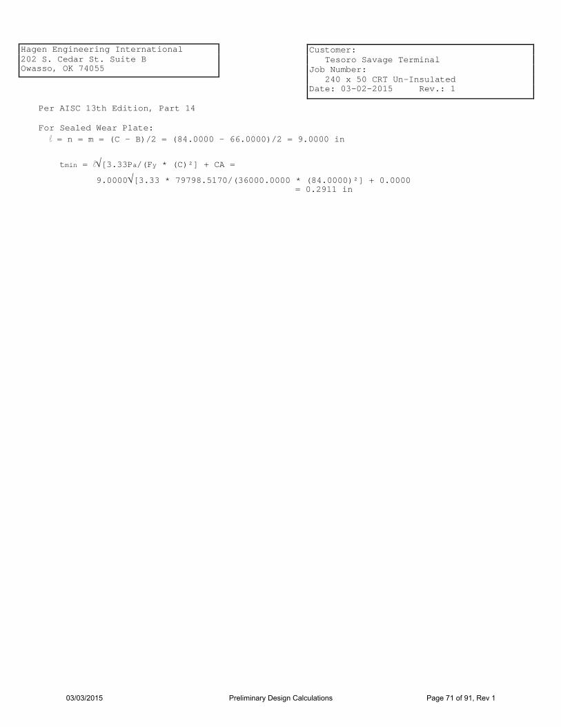
Per AISC 13th Edition, Part 14 For Sealed Wear Plate: l = n = m = (C - B)/2 = (84.0000 - 66.0000)/2 = 9.0000 in
tmin = l√[3.33Pa/(Fy * (C)²] + CA = 9.0000√[3.33 * 79798.5170/(36000.0000 * (84.0000)²] + 0.0000 = 0.2911 in
03/03/2015 Preliminary Design Calculations Page 71 of 91, Rev 1

Hagen Engineering International 202 S. Cedar St. Suite B Owasso, OK 74055
Customer: Tesoro Savage Terminal Job Number: 240 x 50 CRT Un-Insulated Date: 03-02-2015 Rev.: 1
Compression Ring
L4 x4 x3/ 8 per Detail d
4 inches Vertical leg of rim angle is butt welded to the top of the shell with the horizontal leg turned out
Material: A36
API-650 Figure F-2
Rc = 1440.0000 in
R2 = Rc/(sin ø) = 1440.0000/(sin 3.5763) = 23084.9561 in
Roof Angle (ø) = 3.5763°
th = 0.1875 in
wh = 0.3 √(R2th) = 0.3 √(23084.9561 * 0.1875) = 19.7372 in not to exceed 12.0000 in therefore wh = 12.0000 in
Available area from roof (Ar) = thwh = 0.1875 * 12.0000 = 2.2500 in²
wc = 0.6 √(Rctc) = 0.6 √(1440.0000 * 0.4000) = 14.4000 in
tc = 0.4000 in
Distance from top of angle to top of shell (b) = 4.0000 in Available area from shell (As) = (wc - b)tc = (14.4000 - 4.0000) * 0.4000 = 4.1600 in²
Yield strength (Fy) = 36000.0000 psi
ta = 0.3750 in Horizontal projection of angle (a1) = 3.6250 in
Maximum horizontal projection = ta * 3000/√(Fy)= 0.3750 * 3000/√(36000.0000) = 5.9293 in therefore a1 = 3.6250 in Vertical projection of angle (a2) = 4.0000 in Maximum vertical projection = wc = 14.4000 in therefore a2 = 4.0000 in Available area from compression ring (Ac) = (a1 + a2)ta = (3.6250 + 4.0000)0.3750 = 2.8594 in²
Total available area (At) = Ar + As + Ac = 2.2500 + 4.1600 + 2.8594 = 9.2694 in²
Check in Corroded Condition
03/03/2015 Preliminary Design Calculations Page 72 of 91, Rev 1

Hagen Engineering International 202 S. Cedar St. Suite B Owasso, OK 74055
Customer: Tesoro Savage Terminal Job Number: 240 x 50 CRT Un-Insulated Date: 03-02-2015 Rev.: 1
Roof corrosion allowance = 0.0000 in th = Roof thickness - CA = 0.1875 - 0.0000 = 0.1875 in
wh = 0.3 √(R2th) = 0.3 √(23084.9561 * 0.1875) = 19.7372 in not to exceed 12.0000 in therefore wh = 12.0000 in
Available area from roof (Ar) = thwh = 0.1875 * 12.0000 = 2.2500 in²
Shell corrosiona allowance = 0.1875 in tc = shell thickness - CA = 0.4000 - 0.1875 = 0.2125 in
wc = 0.6 √(Rctc) = 0.6 √(1440.0000 * 0.2125) = 10.4957 in
Distance from top of angle to top of shell (b) = 4.0000 in Available area from shell (As) = (wc - b)tc = (10.4957 - 4.0000) * 0.2125 = 1.3803 in²
Angle corrosion allowance = 0.0000 in ta = Angle thickness - CA = 0.3750 - 0.0000 = 0.3750 in Horizontal projection of angle (a1) = 3.6250 in
Maximum horizontal projection = ta * 3000/√(Fy)= 0.3750 * 3000/√(36000.0000) = 5.9293 in therefore a1 = 3.6250 in Vertical projection of angle (a2) = 4.0000 in Maximum vertical projection = wc = 10.4957 in therefore a2 = 4.0000 in Available area from compression ring (Ac) = (a1 + a2)ta = (3.6250 + 4.0000)0.3750 = 2.8594 in²
Total available area (At) = Ar + As + Ac = 2.2500 + 1.3803 + 2.8594 = 6.4897 in²
Tank meets the frangibility requirements of 5.10.2.6.
DLs = 1254076.8087 lbs DLs/(2π * Fy * tan ø) = 1254076.8087/(2π * 36000.0000 * tan 3.5763) = 88.7078 in²
The roof support members shall not be attached to the roof plate.
The roof must be attached to the top angle with a single continuous fillet weld on the top side only that does not exceed 3/16'. No underside welding of roof to top angle (including seal welding) is permitted.
03/03/2015 Preliminary Design Calculations Page 73 of 91, Rev 1
Hagen Engineering International 202 S. Cedar St. Suite B Owasso, OK 74055
Customer: Tesoro Savage Terminal Job Number: 240 x 50 CRT Un-Insulated Date: 03-02-2015 Rev.: 1
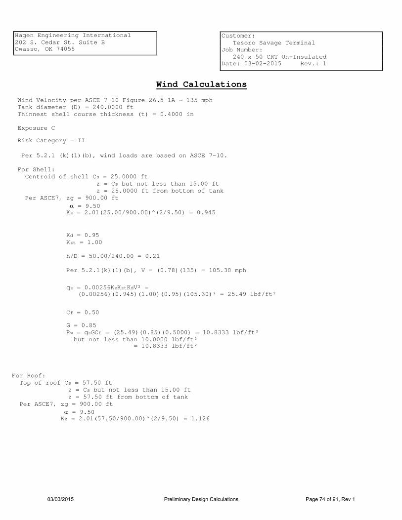
Wind Calculations
Wind Velocity per ASCE 7-10 Figure 26.5-1A = 135 mph Tank diameter (D) = 240.0000 ft Thinnest shell course thickness (t) = 0.4000 in Exposure C
Risk Category = II
Per 5.2.1 (k)(1)(b), wind loads are based on ASCE 7-10. For Shell: Centroid of shell Cs = 25.0000 ft z = Cs but not less than 15.00 ft z = 25.0000 ft from bottom of tank Per ASCE7, zg = 900.00 ft α = 9.50 Kz = 2.01(25.00/900.00)^(2/9.50) = 0.945
Kd = 0.95 Kzt = 1.00 h/D = 50.00/240.00 = 0.21
Per 5.2.1(k)(1)(b), V = (0.78)(135) = 105.30 mph
qz = 0.00256KzKztKdV² = (0.00256)(0.945)(1.00)(0.95)(105.30)² = 25.49 lbf/ft²
Cf = 0.50
G = 0.85 Pw = qzGCf = (25.49)(0.85)(0.5000) = 10.8333 lbf/ft² but not less than 10.0000 lbf/ft² = 10.8333 lbf/ft²
For Roof: Top of roof Cs = 57.50 ft z = Cs but not less than 15.00 ft z = 57.50 ft from bottom of tank Per ASCE7, zg = 900.00 ft α = 9.50 Kz = 2.01(57.50/900.00)^(2/9.50) = 1.126
03/03/2015 Preliminary Design Calculations Page 74 of 91, Rev 1

Hagen Engineering International 202 S. Cedar St. Suite B Owasso, OK 74055
Customer: Tesoro Savage Terminal Job Number: 240 x 50 CRT Un-Insulated Date: 03-02-2015 Rev.: 1
Kd = 0.85 Kzt = 1.00 V = 105.30 mph qz = 0.00256KzKztKdV² = (0.00256)(1.126)(1.00)(0.85)(105.30)² = 27.1783 lbf/ft² GCp = 0.90 Uw = qzGCp = (27.1783)(0.90) = 24.4605 lbf/ft²
Pwr = qzGCf = (27.1783)(0.85)(0.5000) = 11.5508 lbf/ft² but not less than 10.0000 lbf/ft² = 11.55 lbf/ft²
Per 5.9.7.1: Per ASCE7, Kz = 0.95 Kd = 0.95 Kzt = 1.00 V = 120.00 mph G = 0.85 P = 5.00 lbf/ft² Pw = 0.00256KzKztKdV²IG + P = (0.00256)(0.95)(1.00)(0.95)(120.00)²(1.00)(0.85) + 5.00 = 33.1383 lbf/ft² Multiplier (m) = Pw/36.00 = 33.1383/36.00 = 0.9205 not less than 1.0, therefore m = 1.0000
Per 5.9.7.1: H1 = 600000.00t[√(t/D)³](120/V)² = (600000.00)(0.4000)[√(0.4000 / 240.0000)³](120/105.30)² = 21.2075 ft
Per 5.9.7.2: tuniform = t = 0.4000 in
For each shell course, Wtr = W √( tuniform tactual ) 5
Shell Course W (ft) Tactual (in) Wtr (ft)
(Shell courses are numbered from bottom to top)
Angle 0.3917 0.3750 0.3333 5 9.8333 0.4000 9.8333
4 9.9583 0.6240 3.2762
3 9.9583 0.7400 2.1392
2 9.9583 0.9386 1.1807
1 0.6436 1.1964 9.9583
Total Transposed Width: 17.4648
03/03/2015 Preliminary Design Calculations Page 75 of 91, Rev 1

Hagen Engineering International 202 S. Cedar St. Suite B Owasso, OK 74055
Customer: Tesoro Savage Terminal Job Number: 240 x 50 CRT Un-Insulated Date: 03-02-2015 Rev.: 1
Overturning moment: Total shell vertical height (H) = 50.0000 ft Vertical roof area (Ar) = 900.0000 ft² Distance to roof (Hr) = 57.5000 ft Overturning Moment (Mws) = (PwDH²/2 + PwrArHr) = = [(10.8333)(240.0000)(50.0000)²/2 + (11.5508)(900.0000)(57.5000)] = 3847756.9440 ft-lbs
Tank does not contain internal pressure. Therefore, MPi = 0
Check for tank stability without anchors per 5.11.2 Weight of shell (DLS) = 1254076.8087 lbs MDL = DLS * D/2 = 1254076.8087 * 240.0000 / 2 = 150489217.0455 ft-lbs Weight of roof (DLR) = 347093.0752 lbs MDLR = DLR * D/2 = 347093.0752 * 240.0000 / 2 = 41651169.0299 ft-lbs
Bottom thickness used (tb) = 0.3750 in Bottom material yield strength (Fby) = 36000.0000 psi wL = 4.6700tb √(FbyH) = (4.6700)(0.3750)√(36000.0000 * 47.0000) = 2277.9717 lbf/ft
not to exceed 0.450HD = 0.450 * 47.0000 * 240.0000 = 5076.0000 lbf/ft therefore, wL = 2277.9717 lbf/ft
For tank to be stable: Mws + 0.40Mpi < MDL/1.5 + MDLR Mws + 0.40Mpi = (3847756.9440) + (0.40)(0.0000) = 3847756.9440 ft-lbs MDL/1.5 + MDLR = 150489217.0455/1.5 + 41651169.0299 = 141977313.7269 ft-lbs
Check for Sliding (tank empty): Sliding Force (Vw) = [(PwDH + PwrAr)] = [((10.8333)(240.0000)(50.0000) + (11.55)(900.00))] = 140,395.87 lbs
Resistance to Sliding (Vs) = 0.4(Ws + Wr + Wf) = 0.4(1201451.6953 + 545268.2652 + 707430.0397) = 981,660.00 lbs
03/03/2015 Preliminary Design Calculations Page 76 of 91, Rev 1

Hagen Engineering International 202 S. Cedar St. Suite B Owasso, OK 74055
Customer: Tesoro Savage Terminal Job Number: 240 x 50 CRT Un-Insulated Date: 03-02-2015 Rev.: 1
131517746.9188
907306.2601
475843.3218
347093.0752
1130973.3553
1140021.1421
0.0000
0.0000
0.0000
198175.1899
545268.2652
0.0000
0.0000
0.0000
343312.6708
346059.1721
105156.6711
52625.1134
7389.0259
131517746.9188
1194062.6694
707430.0397
347093.0752
1130973.3553
1140021.1421
0.0000
0.0000
0.0000
198175.1899
545268.2652
0.0000
0.0000
0.0000
343312.6708
346059.1721
105156.6711
52625.1134
7389.0259
Corroded (lbf) New (lbf)
Product: Total Shell Plates: Total Bottom Plates: Total Roof Plates: Total Live Load: Total Snow Load: Total Additional Dead Load: Shell Insulation: Roof Insulation: Total Rafters: Total Roof and Framing: Total Shell Appurtenances: Total Roof Appurtenances: Total Roof Appurtenances acting on Shell Live Load acting on Shell: Snow Load acting on Shell: Total of Roof acting on Shell: Total of Roof Structural acting on Shell: Total Compression Ring and Shell Stiffener
Weights
03/03/2015 Preliminary Design Calculations Page 77 of 91, Rev 1

Hagen Engineering International 202 S. Cedar St. Suite B Owasso, OK 74055
Customer: Tesoro Savage Terminal Job Number: 240 x 50 CRT Un-Insulated Date: 03-02-2015 Rev.: 1
Seismic Calculations
Tank diameter (D): 240.0000 ft Product Height (H): 47.0000 ft Specific Gravity (G): 1.0000 Tank is self-anchored Mapped spectral response acceleration (Ss): 0.9400 g Mapped spectral response acceleration (S1): 0.4120 g Mapped spectral response acceleration (S0) = 0.4Ss = (0.4)(0.9400) = 0.3760 g Mapped spectral response acceleration (SP) = 0.8S1 = (0.8)(0.4120) = 0.3296 g Site Class per E.4.4 : E Seismic Use Group per E.3.1 : I From Table E-1, Fa = 0.9720 From Table E-2, Fv = 2.4000 From Table E-5, I = 1.0000 From Table E-4, Rwi = 3.5000 From Table E-4, Rwc = 2.0000 Scaling factor per E.2, Q = 2/3 SDS = QFaSs = (2/3)(0.9720)(0.9400) = 0.6091 SD1 = QFvS1 = (2/3)(2.4000)(0.4120) = 0.6592
Per E.6.1.3, Av = 0.7 x Purchaser specified vertical acceleration Vertical earthquake acceleration coefficient (Av): 0.0000 g
E.4.5.2 Convective (Sloshing) Period
Per E4.5.2-b: Tc = 1.0Ks√D = (1.0)(0.7357)√240.0000 = 11.3967
) (3.68)(47.0000) 240.0000 ( tanh √ ) 3.68H
D ( tanh √
Ks = ______0.578 = __________0.578 = 0.7357
E.4.5.2-c:
E.4.6.1 Spectral Acceleration Coefficients Impulsive spectral acceleration parameter:
= 0.1740 ) 1.00 3.5000 ( = 0.6091
I Rwi ) (
Per E.4.6.1-1: Ai = SDS
per E.4.6.1-3: Ai ≥ 0.5S1 ( ( I
Rwi 1.00
3.5000 ) ) = (0.5)(0.4120) = 0.0589
03/03/2015 Preliminary Design Calculations Page 78 of 91, Rev 1

Hagen Engineering International 202 S. Cedar St. Suite B Owasso, OK 74055
Customer: Tesoro Savage Terminal Job Number: 240 x 50 CRT Un-Insulated Date: 03-02-2015 Rev.: 1
However, per E.4.6.1-2, Ai ≥ 0.0070 Therefore, Ai = 0.1740
TL = 16.0000 K = 1.5
Convective spectral acceleration parameter:
= 0.0434 1.00 2.0000
1 11.3967 = (1.5)(0.6592) I
Rwc 1 Tc ) ) ) ) ( ( ( ( Ac = KSD1
Tc ≤ TL , Per E.4.6.1-4
However, Ac ≤ Ai Therefore, Ac = 0.0434
Per E.6.1.1 D/H = 240.0000/47.0000 = 5.1064 Weights: Ws = 1201452 lbs Wf = 707430 lbs Wr = Roof weight + 10% of snow = 659270 lbs WP = 131517747 lbs
(131517747) = 29732254 lbs tanh(0.866 * 5.1064) 0.866 * 5.1064 WP = tanh(0.866D/H)
0.866D/H
D/H ≥ 1.333
Per E.6.1.1-1, Wi =
Per E.6.1.1-3, Wc = 0.230D/H tanh(3.67H/D)WP = (0.230)(5.1064)[tanh(3.67/5.1064)](131517747) = 95166223 lbs
Per E.6.1-2, Vi = Ai(Ws + Wr + Wf + Wi) = (0.1740)(1201452 + 659270 + 707430 + 29732254) = 5621378 lbs Per E.6.1-3, Vc = AcWc = (0.0434)(95166223) = 4128419 lbs Per E.6.1-1, V = √(Vi² + Vc²) = √[(5621378)² + (4128419)²] = 6974506 lbs
Per E.6.1.2.1
Per E.6.1.2.1-1, Xi = 0.375H = (0.375)(47.0000) = 17.6250 ft
D/H ≥ 1.333
03/03/2015 Preliminary Design Calculations Page 79 of 91, Rev 1

Hagen Engineering International 202 S. Cedar St. Suite B Owasso, OK 74055
Customer: Tesoro Savage Terminal Job Number: 240 x 50 CRT Un-Insulated Date: 03-02-2015 Rev.: 1
Per E.6.1.2.1-3, Xc = [
[ ] 1.0 -
cosh(3.67H/D) - 1 3.67H/D sinh(3.67H/D) H =
1.0 - cosh(3.67/5.1064) - 1
(3.67/5.1064)sinh(3.67/5.1064) ] (47.0000) = 24.4619 ft
Per E.6.1.2.2
98.0549 ft
)] - 1.0 ( (0.866 * 5.1064) tanh(0.866 * 5.1064) 1.0 + 1.333 [ 0.375
H = - 1.0 )] (0.866D/H) tanh(0.866D/H) ( 1.0 + 1.333 [ Per E.6.1.2.2-1,
Xis = 0.375
D/H ≥ 1.333
(47.0000) =
Per E.6.1.2.2-3, Xcs = [ 1.0 - cosh(3.67H/D) -1.937
3.67H/D sinh(3.67H/D) ] H =
[ 1.0 - cosh(3.67/5.1064) - 1.937 (3.67/5.1064)sinh(3.67/5.1064) ] (47.0000) = 102.7989 ft
Per E.6.1.5-1, Mrw = √[Ai(WiXi + WsXs + WrXr)]² + [Ac(WcXc)]² = √[0.1740(29732254*17.6250 + 1201452*19.9796 + 659270*52.5000)]² + [0.0434(95166223*24.4619)]² = 143111329 ft-lbs
Per E.6.1.5
Per E.6.1.5-2, Ms = √[Ai(WiXis + WsXs + WrXr)]² + [Ac(WcXcs)]² = √[0.1740(29732254*98.0549 + 1201452*19.9796 + 659270*52.5000)]² + [0.0434(95166223*102.7989)]² = 669328931 ft-lbs
Self-anchored tank (new condition)
Per E.6.2.1.1.1 Ws = 1201452 lbs wrs = 255.1621 lbf/ft ta = 0.5000 in ts = 1.0088 in Ge = G(1.0 - 0.4Av) = 1.0000(1.0 - (0.4)(0.0000)) = 1.0000 Per E.6.2.1.1.1-2, wt = Ws/(πD) + wrs = 1201452/(π ∗ 240.0000) + 255.1621 = 1848.6369 lbf/ft
03/03/2015 Preliminary Design Calculations Page 80 of 91, Rev 1

Hagen Engineering International 202 S. Cedar St. Suite B Owasso, OK 74055
Customer: Tesoro Savage Terminal Job Number: 240 x 50 CRT Un-Insulated Date: 03-02-2015 Rev.: 1
Check annular ring: Per E.6.2.1.1.2-1b, L = 0.21600ta√(Fy/HGe) = (0.21600)(0.5000)√[36000.0000/(47.0000 * 1.0000)] = 2.9890 ft ≤ 0.035D = (0.035)(240.0000) = 8.4000 ft therefore, L = 2.9890 ft
Ls = 2.9003 ft Per E.6.2.1.1-2b, wa = 36.5HGeLs = (36.5)(47.0000)(1.0000)(2.9003) = 4975.4647 lbf/ft
= 0.364 143111329 (240.0000)²[1848.6369(1.0 - (0.4)(0.0000)) + 4975.4647 - 0.40 * 0.0000]
= Mrw D²[wt(1.0 - 0.4Av) + wa - 0.40wint]
Per E.6.2.1.1.1-1, J =
Wint = 0.0000 lbf/ft
Shell compression per E.6.2.2.1-1b where J < 0.785
σc = [wt(1 + 0.4Av) + 1.273Mrw/D²]/(12ts) = [1848.6369(1 + (0.4)(0.0000)) + (1.273)(143111329)/(240.0000)²]/(12 * 1.0088) = 413.9752 psi
Self-anchored tank (corroded condition)
Per E.6.2.1.1.1 Ws = 914695 lbs wrs = 255.1621 lbf/ft ta = 0.3750 in ts = 1.0088 in Ge = G(1.0 - 0.4Av) = 1.0000(1.0 - (0.4)(0.0000)) = 1.0000 Per E.6.2.1.1.1-2, wt = Ws/(πD) + wrs = 914695/(π ∗ 240.0000) + 255.1621 = 1468.3144 lbf/ft
Check annular ring: Per E.6.2.1.1.2-1b, L = 0.21600ta√(Fy/HGe) = (0.21600)(0.3750)√[36000.0000/(47.0000 * 1.0000)] = 2.2418 ft ≤ 0.035D = (0.035)(240.0000) = 8.4000 ft therefore, L = 2.2418 ft
Per E.6.2.1.1-1b, wa = 7.9ta√(FyHGe) = (7.9)(0.3750)√[(36000.0000)(47.0000)(1.0000)] = 3853.5282 lbf/ft ≤ 1.28HDGe = (1.28)(47.0000)(240.0000)(1.0000) = 14438.4000 lbf/ft therefore, wa = 3853.5282 lbf/ft
03/03/2015 Preliminary Design Calculations Page 81 of 91, Rev 1

Hagen Engineering International 202 S. Cedar St. Suite B Owasso, OK 74055
Customer: Tesoro Savage Terminal Job Number: 240 x 50 CRT Un-Insulated Date: 03-02-2015 Rev.: 1
Per E.6.2.1.1.1-1, J = Mrw D²[wt(1.0 - 0.4Av) + wa - 0.40wint]
=
143111329 (240.0000)²[1468.3144(1.0 - (0.4)(0.0000)) + 3853.5282 - 0.40 * 0.0000]
= 0.467
σc = [wt(1 + 0.4Av) + 1.273Mrw/D²]/(12ts) = [1468.3144(1 + (0.4)(0.0000)) + (1.273)(143111329)/(240.0000)²]/(12 * 1.0088) = 383 psi
Shell compression per E.6.2.2.1-1b where J < 0.785
Allowable Compression Stresses in Shell per E.6.2.2.3
For new condition: GHD²/t² = (1.0000)(47.0000)(240.0000)²/(1.0088)² = 2660092
For GHD²/t² ≥ 1000000 Per E.6.2.2.3-1b, Fc = 1000000ts/D = (1000000)(1.0088)/240.0000 = 4203 psi
For corroded condition: GHD²/t² = (1.0000)(47.0000)(240.0000)²/(1.0088)² = 2660092
For GHD²/t² ≥ 1000000 Per E.6.2.2.3-1b, Fc = 1000000ts/D = (1000000)(1.0088)/240.0000 = 4203 psi
Freeboard requirements per E.7.2
Tc > 4 Per E.7.2-3, Af = KSD1I(4/Tc²) = (1.5)(0.6592)(1.0000)(4/11.3967²) = 0.0305
Freeboard equal to 0.7 times the calculated wave height is recommended but not required. The required minimum freeboard = 2.149. The available freeboard = 2.000.
Wave Height Per E.7.2-1: δs = 0.42DAf = (0.42)(240.0000)(0.0305) = 3.0695 ft Per Table E-7, minimum freeboard = 0.7δs = (0.7)(3.0695) = 2.1487 ft
Per E.6.2.1.1.3, butt welded annular plates are required.
Estimated Tank Uplift per E.7.3.1-1b tb = 0.3750 in yu = FyL²/(83300)(tb) = (36000)(2.2418)²/(83300)(0.3750) = 5.7916 in
Tank resistance to sliding per E.7.6 Per E.7.6-1, Vs = 0.4000(Ws + Wr + Wf + Wp)(1.0 - 0.4Av) = 0.4000(914695 + 659270 + 475843 + 131517747)(1.0 - 0.4 * 0.0000) = 53427022 lbs V = 6974506 lbs
03/03/2015 Preliminary Design Calculations Page 82 of 91, Rev 1
Hagen Engineering International 202 S. Cedar St. Suite B Owasso, OK 74055
Customer: Tesoro Savage Terminal Job Number: 240 x 50 CRT Un-Insulated Date: 03-02-2015 Rev.: 1
Tank is stable against sliding.
03/03/2015 Preliminary Design Calculations Page 83 of 91, Rev 1

Hagen Engineering International 202 S. Cedar St. Suite B Owasso, OK 74055
Customer: Tesoro Savage Terminal Job Number: 240 x 50 CRT Un-Insulated Date: 03-02-2015 Rev.: 1
Hoop Stress per E.6.1.4
G = 1.00 D = 240.0000 ft H = 47.0000 ft Ai = 0.1740 Ac = 0.0434 Av = 0.0000 D/H = 5.1064
Shell Course 01
Y = 47.0000 ft
D/H ≥ 1.333
Per E.6.1.4-1b, Ni = 4.50AiGDH [ Y H - 0.5 ( Y H ) 2
] tanh(0.866D/H) =
(4.50)(0.1740)(1.00)(240.0000)(47.0000) [ 47.0000 47.0000 - 0.5 ( 47.0000
47.0000 ) 2 ]
tanh(0.866 * 240.0000 / 47.0000) = 4415.7164 lbf/in
Per E.6.1.4-4b, Nc = 0.98AcGD²cosh[3.68(H - Y)/D] cosh[3.68H/D]
(0.98)(0.0434)(1.0000)(240.0000)²cosh[3.68(47.0000 - 47.0000)/240.0000] cosh[(3.68)(47.0000/240.0000)]
=
= 1926.4797 lbf/in
Nh = 2.60D(Y-1)G = (2.60)(240.0000)((47.0000)-1)(1.00) = 28704.0000 lbf/in
Shell thickness (t) = 1.0089 in
Per E.6.1.4-5, σT = [Nh + √Ni² + Nc²]/t = [28704.0000 + √(4415.7164)² + (1926.4797)²]/1.0089 = 33225.9519 psi
03/03/2015 Preliminary Design Calculations Page 84 of 91, Rev 1

Hagen Engineering International 202 S. Cedar St. Suite B Owasso, OK 74055
Customer: Tesoro Savage Terminal Job Number: 240 x 50 CRT Un-Insulated Date: 03-02-2015 Rev.: 1
Allowable stress per E.6.2.4 Lesser of: 1.33SE = (1.33)(28000.0000)(1.0000) = 37240.0000 psi or 0.90FyE = (0.90)(42000.0000)(1.0000) = 37800.0000 psi Therefore, Allowable stress = 37240.0000 psi
Minimum required thickness = (σT * t)/Sa = (33225.9519 * 1.0089)/37240.0000 = 0.9002 in
03/03/2015 Preliminary Design Calculations Page 85 of 91, Rev 1

Hagen Engineering International 202 S. Cedar St. Suite B Owasso, OK 74055
Customer: Tesoro Savage Terminal Job Number: 240 x 50 CRT Un-Insulated Date: 03-02-2015 Rev.: 1
Shell Course 02
Y = 37.0417 ft
D/H ≥ 1.333
Per E.6.1.4-1b, Ni = 4.50AiGDH [ Y H - 0.5 ( Y H ) 2
] tanh(0.866D/H) =
(4.50)(0.1740)(1.00)(240.0000)(47.0000) [ 37.0417 47.0000 - 0.5 ( 37.0417
47.0000 ) 2 ]
tanh(0.866 * 240.0000 / 47.0000) = 4217.4821 lbf/in
Per E.6.1.4-4b, Nc = 0.98AcGD²cosh[3.68(H - Y)/D] cosh[3.68H/D]
(0.98)(0.0434)(1.0000)(240.0000)²cosh[3.68(47.0000 - 37.0417)/240.0000] cosh[(3.68)(47.0000/240.0000)]
=
= 1948.9818 lbf/in
Nh = 2.60D(Y-1)G = (2.60)(240.0000)((37.0417)-1)(1.00) = 22490.0000 lbf/in
Shell thickness (t) = 0.7511 in
Per E.6.1.4-5, σT = [Nh + √Ni² + Nc²]/t = [22490.0000 + √(4217.4821)² + (1948.9818)²]/0.7511 = 36128.3981 psi
Allowable stress per E.6.2.4 Lesser of: 1.33SE = (1.33)(28000.0000)(1.0000) = 37240.0000 psi or 0.90FyE = (0.90)(42000.0000)(1.0000) = 37800.0000 psi Therefore, Allowable stress = 37240.0000 psi
Minimum required thickness = (σT * t)/Sa = (36128.3981 * 0.7511)/37240.0000 = 0.7287 in
03/03/2015 Preliminary Design Calculations Page 86 of 91, Rev 1

Hagen Engineering International 202 S. Cedar St. Suite B Owasso, OK 74055
Customer: Tesoro Savage Terminal Job Number: 240 x 50 CRT Un-Insulated Date: 03-02-2015 Rev.: 1
Shell Course 03
Y = 27.0833 ft
D/H ≥ 1.333
Per E.6.1.4-1b, Ni = 4.50AiGDH [ Y H - 0.5 ( Y H ) 2
] tanh(0.866D/H) =
(4.50)(0.1740)(1.00)(240.0000)(47.0000) [ 27.0833 47.0000 - 0.5 ( 27.0833
47.0000 ) 2 ]
tanh(0.866 * 240.0000 / 47.0000) = 3622.7793 lbf/in
Per E.6.1.4-4b, Nc = 0.98AcGD²cosh[3.68(H - Y)/D] cosh[3.68H/D]
(0.98)(0.0434)(1.0000)(240.0000)²cosh[3.68(47.0000 - 27.0833)/240.0000] cosh[(3.68)(47.0000/240.0000)]
=
= 2017.0140 lbf/in
Nh = 2.60D(Y-1)G = (2.60)(240.0000)((27.0833)-1)(1.00) = 16276.0000 lbf/in
Shell thickness (t) = 0.5525 in
Per E.6.1.4-5, σT = [Nh + √Ni² + Nc²]/t = [16276.0000 + √(3622.7793)² + (2017.0140)²]/0.5525 = 36963.6728 psi
Allowable stress per E.6.2.4 Lesser of: 1.33SE = (1.33)(28000.0000)(1.0000) = 37240.0000 psi or 0.90FyE = (0.90)(42000.0000)(1.0000) = 37800.0000 psi Therefore, Allowable stress = 37240.0000 psi
Minimum required thickness = (σT * t)/Sa = (36963.6728 * 0.5525)/37240.0000 = 0.5484 in
03/03/2015 Preliminary Design Calculations Page 87 of 91, Rev 1

Hagen Engineering International 202 S. Cedar St. Suite B Owasso, OK 74055
Customer: Tesoro Savage Terminal Job Number: 240 x 50 CRT Un-Insulated Date: 03-02-2015 Rev.: 1
Shell Course 04
Y = 17.1250 ft
D/H ≥ 1.333
Per E.6.1.4-1b, Ni = 4.50AiGDH [ Y H - 0.5 ( Y H ) 2
] tanh(0.866D/H) =
(4.50)(0.1740)(1.00)(240.0000)(47.0000) [ 17.1250 47.0000 - 0.5 ( 17.1250
47.0000 ) 2 ]
tanh(0.866 * 240.0000 / 47.0000) = 2631.6078 lbf/in
Per E.6.1.4-4b, Nc = 0.98AcGD²cosh[3.68(H - Y)/D] cosh[3.68H/D]
(0.98)(0.0434)(1.0000)(240.0000)²cosh[3.68(47.0000 - 17.1250)/240.0000] cosh[(3.68)(47.0000/240.0000)]
=
= 2132.1656 lbf/in
Nh = 2.60D(Y-1)G = (2.60)(240.0000)((17.1250)-1)(1.00) = 10062.0000 lbf/in
Shell thickness (t) = 0.4365 in
Per E.6.1.4-5, σT = [Nh + √Ni² + Nc²]/t = [10062.0000 + √(2631.6078)² + (2132.1656)²]/0.4365 = 30810.9021 psi
Allowable stress per E.6.2.4 Lesser of: 1.33SE = (1.33)(23200.0000)(1.0000) = 30856.0000 psi or 0.90FyE = (0.90)(36000.0000)(1.0000) = 32400.0000 psi Therefore, Allowable stress = 30856.0000 psi
Minimum required thickness = (σT * t)/Sa = (30810.9021 * 0.4365)/30856.0000 = 0.4359 in
03/03/2015 Preliminary Design Calculations Page 88 of 91, Rev 1

Hagen Engineering International 202 S. Cedar St. Suite B Owasso, OK 74055
Customer: Tesoro Savage Terminal Job Number: 240 x 50 CRT Un-Insulated Date: 03-02-2015 Rev.: 1
Shell Course 05
Y = 7.1667 ft
D/H ≥ 1.333
Per E.6.1.4-1b, Ni = 4.50AiGDH [ Y H - 0.5 ( Y H ) 2
] tanh(0.866D/H) =
(4.50)(0.1740)(1.00)(240.0000)(47.0000) [ 7.1667 47.0000 - 0.5 ( 7.1667
47.0000 ) 2 ]
tanh(0.866 * 240.0000 / 47.0000) = 1243.9678 lbf/in
Per E.6.1.4-4b, Nc = 0.98AcGD²cosh[3.68(H - Y)/D] cosh[3.68H/D]
(0.98)(0.0434)(1.0000)(240.0000)²cosh[3.68(47.0000 - 7.1667)/240.0000] cosh[(3.68)(47.0000/240.0000)]
=
= 2297.1265 lbf/in
Nh = 2.60D(Y-1)G = (2.60)(240.0000)((7.1667)-1)(1.00) = 3848.0000 lbf/in
Shell thickness (t) = 0.2125 in
Per E.6.1.4-5, σT = [Nh + √Ni² + Nc²]/t = [3848.0000 + √(1243.9678)² + (2297.1265)²]/0.2125 = 30401.5330 psi
Allowable stress per E.6.2.4 Lesser of: 1.33SE = (1.33)(23200.0000)(1.0000) = 30856.0000 psi or 0.90FyE = (0.90)(36000.0000)(1.0000) = 32400.0000 psi Therefore, Allowable stress = 30856.0000 psi
Minimum required thickness = (σT * t)/Sa = (30401.5330 * 0.2125)/30856.0000 = 0.2094 in
03/03/2015 Preliminary Design Calculations Page 89 of 91, Rev 1


PROJECT ENGINEER
Hagen Engineering Int rnati nal 202 S. Cedar St. Su te B
Owasso, OK 74055
(651) 3 5-46 6
DESIGN ENGINEER
Doug Bayles, P.E.
HEI Job Number: 15-1006
TANK CALCULATIONS
T-Bailey
Tesoro Savage Petroleum Terminal, LLC Tesoro Savage Vancouver Energy
Port of Vancouver, WA
Crude Oil Insulated Storage Tank
240´ Diameter x 50´ High Cone Roof Tank
Preliminary Design Calculat ons
03/03/2015 Preliminary Design Calculations Page 1 of 91, Rev 1
DRAFT

Hagen Engineering International 202 S. Cedar St. Suite B Owasso, OK 74055
Customer: Tesoro Savage Terminal Job Number: 240 x 50 CRT Insulated Date: 03-03-2015 Rev.: 1
Standard Compliant Issues
Shell Shell Course 1 requires impact testing per the standard. Shell Course 2 requires impact testing per the standard.
03/03/2015 Preliminary Design Calculations Page 2 of 91, Rev 1


Hagen Engineering International 202 S. Cedar St. Suite B Owasso, OK 74055
Customer: Tesoro Savage Terminal Job Number: 240 x 50 CRT Insulated Date: 03-03-2015 Rev.: 1
Hagen Engineering International 202 S. Cedar St. Suite B Owasso, OK 74055
Customer: Tesoro Savage Terminal Job Number: 240 x 50 CRT Insulated Date: 03-03-2015 Rev.: 1
Design Data
Tank Diameter .......................................... 240'- 0.0000"
Tank Height ............................................
High Liquid Level ......................................
Low Liquid Level .......................................
50'- 0.0000"
47'- 0.0000"
4'- 0.0000"
(Outside)
Total Capacity .........................................
Working Capacity .......................................
15,765,268 gallons
375,364 barrels
14,357,570 gallons
341,847 barrels
Normal Liquid Level .................................... 46'- 6.0000"
Design Standard......................................... API-650 12th Edition, Add. 1, Annex E
25 °F
25.00 psf Roof Live Load .........................................
150 °F
150 °F
Design Temperature .....................................
Operating Temperature ..................................
Design Metal Temperature ...............................
30.00 psf Ground Snow Load ...................................... 25.20 psf Roof Design Snow Load (0.84 x Ground Snow Load)......
Additional Roof Loads ................................... 0.00 psf
Velocity per ASCE 7-10 Figure 26.5-1A . . . . . . . . . 135 mph
Wind:
Risk Category ....................................... II
C Exposure ...........................................
03/03/2015 Preliminary Design Calculations Page 4 of 91, Rev 1

Hagen Engineering International 202 S. Cedar St. Suite B Owasso, OK 74055
Customer: Tesoro Savage Terminal Job Number: 240 x 50 CRT Insulated Date: 03-03-2015 Rev.: 1
16 Transitional Period (TL) ...........................
0.00 g Vertical Acceleration ..............................
Site Class .........................................
Importance Factor ..................................
Use Group ..........................................
Ss Value ...........................................
S1 Value ...........................................
E
1.00
I
94.00 %
41.20 %
Seismic:
Specific Gravity ....................................... 1.000
Internal Pressure (Design).............................. Atmospheric
(Operating).............................. Atmospheric
Atmospheric (Operating)..............................
External Pressure (Design).............................. 1.00 inches of water
Corrosion Allowance:
Bottom ............................................. 0.1250 in
Annular Ring ....................................... 0.1250 in
Shell Courses 1 - 3 ................................ 0.1875 in
Courses 4 - 4 ................................ 0.1875 in
0.1875 in Courses 5 - 5 ................................
0.0000 in Roof ...............................................
Rafters............................................. 0.0000 in
Cap Plate...........................................
Base Plate..........................................
0.0000 in
0.0000 in
Columns............................................. 0.0000 in
0.0000 in Compression Ring ...................................
Shell is insulated with 3.0000 in thick insulation (Weight - 0.7800 psf)
Roof is insulated with 3.0000 in thick insulation (Weight - 0.7800 psf)
03/03/2015 Preliminary Design Calculations Page 5 of 91, Rev 1

Hagen Engineering International 202 S. Cedar St. Suite B Owasso, OK 74055
Customer: Tesoro Savage Terminal Job Number: 240 x 50 CRT Insulated Date: 03-03-2015 Rev.: 1
Summary
Total Weight of Insulation: 64,761 lbs
Total Weight of Tank: 2,577,353 lbs Total Operating Weight: 134,159,860 lbs Total Testing Weight: 134,159,860 lbs
Primary Bottom – See Bottom of Page for Secondary Bottom and Dead Shell Bottom with Annular Ring Sloped Up 1.0000 in 120: 0.3750 in (A36) PL (weight: 656,750 lbs)
Annular Ring: 0.5000 in (A36 MOD) PL (weight: 50,680 lbs)
Outside projection = 2.0000 in
Total width: 38.0000 in
Shell
Shell Course 01: 1.1964 in (A573-70) PL x 119.5000 in wide (weight: 366,868 lbs)
Shell Course 1 requires impact testing per the standard.
Shell Course 02: 0.9386 in (A573-70) PL x 119.5000 in wide (weight: 287,815 lbs)
Shell Course 2 requires impact testing per the standard.
Shell Course 03: 0.7400 in (A573-70) PL x 119.5000 in wide (weight: 226,916 lbs)
Shell Course 04: 0.6240 in (A36 MOD) PL x 119.5000 in wide (weight: 191,345 lbs)
Shell Course 05: 0.4000 in (A36 MOD) PL x 118.0000 in wide (weight: 121,118 lbs)
Supported Cone Roof
Roof Slope: 0.7500 in 12 ø: 3.5763° Roof Rise: 7.5000 ft
0.1875 in (A36) PL (weight: 347,093 lbs)
Roof is single lap welded Secondary Bottom 0.2360 in (A36 MOD) PL Outside projection = 2.0000 in Dead Shell or Vertical Spacer Plate Dead Shell: 1.1964 inch (A573-70) PL x 1 ¼” in
03/03/2015 Preliminary Design Calculations Page 6 of 91, Rev 1


Hagen Engineering International 202 S. Cedar St. Suite B Owasso, OK 74055
Customer: Tesoro Savage Terminal Job Number: 240 x 50 CRT Insulated Date: 03-03-2015 Rev.: 1
Bottom Design
Bottom with Annular Ring Sloped Up 1.0000 in 120
Material Grade: A36
in 0.3750 Thickness (tb):
in 0.1250 Corrosion Allowance (CA):
Minimum thickness per 5.4.1 = 0.2360 in
Minimum thickness + corrosion allowance = 0.2360 + 0.1250 = 0.3610 in
Annular Ring
Material Grade: A36 MOD
in 0.5000 Thickness (tb):
in 0.1250 Corrosion Allowance (CA):
Actual outside projection (p) = 2.0000 in
Minimum required outside projection per 5.4.2 = 2.0000 in
Minimum thickness per 5.4.1 = 0.2360 in
td = 1.1963 in tt = 0.9448 in t = 1.1964 in CA = 0.1875 in Sd = 28000.0000 psi St = 30000.0000 psi
Annular ring width: 38.0000 in
sd = ((td - CA)/(t - CA))Sd = ((1.1963 - 0.1875)/(1.1964 - 0.1875)) * 28000.0000 = 27998 psi
st = (tt/t)St = (0.9448 /1.1964) * 30000.0000 = 23690 psi
From Table 5-1, minimum thickness = 0.3438 in
Minimum thickness + corrosion allowance = 0.3438 + 0.1250 = 0.4688 in
Minimum annular ring width inside shell per 5.5.2 = 24.0000 in Fy = 36000.00 psi ϒ = 0.4333 psi/ft Per 5.5.2, width = 2tb √(Fy/(2ϒGH)) = (2 * 0.5000)√(36000.00/(2 * 0.4333 * 1.0000 * 47.0000)) = 29.7287 in
03/03/2015 Preliminary Design Calculations Page 10 of 91, Rev 1

Hagen Engineering International 202 S. Cedar St. Suite B Owasso, OK 74055
Customer: Tesoro Savage Terminal Job Number: 240 x 50 CRT Insulated Date: 03-03-2015 Rev.: 1
Shell Design
Diameter (D) = 240.0000 ft Specific Gravity (G) = 1.000
Shell Height: 9.9583 ft Material Grade: A573-70
Shell Course 01
Product Design Stress per Table 5-2 (Sd) = 28000.0000 psi
H = 47.0000 ft
Hydrostatic Test Stress per Table 5-2 (St) = 30000.0000 psi
Corrosion Allowance (CA): 0.1875 in
For Design per 5.6.4.3 and 5.6.3.2:
tpd = (2.6)(47.0000 - 1.0)(240.0000)(1.0000) 28000.0000 + 0.1875 = 1.2126 in
For Design per 5.6.4.4:
t1d (need not be greater than tpd) = 1.1963 in
+ 0.1875 = 1.1963 in (2.6000)(47.0000)(240.0000)(1.0000) 28000.0000
) √( (47.0000)(1.0000) 28000.0000 1.06 - (0.4630)(240.0000)
47.0000 t1d =
For Hydrotest per 5.6.4.3 and 5.6.3.2:
= 0.9568 in (2.6)(47.0000 - 1.0)(240.0000) 30000.0000
tpt =
For Hydrotest per 5.6.4.4:
t1t = 1.06 - (0.4630)(240.0000) 47.0000 √( 47.0000
30000.0000 ) (2.6000)(47.0000)(240.0000)
30000.0000 = 0.9448 in t1t (need not be greater than tpt) = 0.9448 in
03/03/2015 Preliminary Design Calculations Page 11 of 91, Rev 1
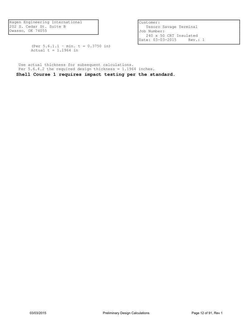
Hagen Engineering International 202 S. Cedar St. Suite B Owasso, OK 74055
Customer: Tesoro Savage Terminal Job Number: 240 x 50 CRT Insulated Date: 03-03-2015 Rev.: 1
(Per 5.6.1.1 - min. t = 0.3750 in) Actual t = 1.1964 in
Use actual thickness for subsequent calculations. Per 5.6.4.2 the required design thickness = 1.1964 inches.
Shell Course 1 requires impact testing per the standard.
03/03/2015 Preliminary Design Calculations Page 12 of 91, Rev 1

Hagen Engineering International 202 S. Cedar St. Suite B Owasso, OK 74055
Customer: Tesoro Savage Terminal Job Number: 240 x 50 CRT Insulated Date: 03-03-2015 Rev.: 1
Shell Height: 9.9583 ft Material Grade: A573-70
Shell Course 02
Product Design Stress per Table 5-2 (Sd) = 28000.0000 psi
H = 37.0417 ft
Hydrostatic Test Stress per Table 5-2 (St) = 30000.0000 psi
Corrosion Allowance (CA): 0.1875 in
For Design per 5.6.4.5:
h1 √(r t1)
= 119.5000
√(1440.0000*1.0089) = 3.1352 hd =
x1 = (0.61)√(1440.0000*0.7510) + (3.8400)(0.1557)(37.0417) = 42.2015 x2 = (12)(0.1557)(37.0417) = 69.1924 x3 = (1.22)√(1440.0000*0.7510) = 40.1198 x = smaller of x1, x2, and x3 = 40.1198
= 0.1557 (√1.3434)(1.3434-1) 1 + (1.3434)^1.5
C = tu = 0.7510 tL = 1.0089 K = tL/tu = 1.0089/0.7510 = 1.3434
For Design per 5.6.4.6:
= 0.7510 in (2.6)(240.0000)(37.0417 - 40.1198/12)(1.0000)
28000.0000 tdx =
t2d = t2a = tdx + CA = 0.7510 + 0.1875 = 0.9385 in
For Hydrotest per 5.6.4.5:
ht = h1
√(r t1) = 119.5000
√(1440.0000*1.1964) = 2.8790
x1 = (0.61)√(1440.0000*0.7032) + (3.8400)(0.2842)(37.0417) = 59.8353 x2 = (12)(0.2842)(37.0417) = 126.3266 x3 = (1.22)√(1440.0000*0.7032) = 38.8216 x = smaller of x1, x2, and x3 = 38.8216
= 0.2842 (√1.7014)(1.7014-1) 1 + (1.7014)^1.5
C = tu = 0.7032 tL = 1.1964 K = tL/tu = 1.1964/0.7032 = 1.7014
For Hydrotest per 5.6.4.6:
ttx = (2.6)(240.0000)(37.0417 - 38.8216/12) 30000.0000 = 0.7032 in
t2t = t2a = tdt = 0.7032 in
03/03/2015 Preliminary Design Calculations Page 13 of 91, Rev 1

Hagen Engineering International 202 S. Cedar St. Suite B Owasso, OK 74055
Customer: Tesoro Savage Terminal Job Number: 240 x 50 CRT Insulated Date: 03-03-2015 Rev.: 1
(Per 5.6.1.1 - min. t = 0.3750 in) Actual t = 0.9386 in
Use actual thickness for subsequent calculations. Per 5.6.4.2 the required design thickness = 0.9386 inches.
Shell Course 2 requires impact testing per the standard.
Shell Height: 9.9583 ft Material Grade: A573-70
Shell Course 03
Product Design Stress per Table 5-2 (Sd) = 28000.0000 psi
H = 27.0833 ft
Hydrostatic Test Stress per Table 5-2 (St) = 30000.0000 psi
Corrosion Allowance (CA): 0.1875 in
x1 = (0.61)√(1440.0000*0.5404) + (3.8400)(0.1742)(27.0833) = 35.1367 x2 = (12)(0.1742)(27.0833) = 56.6275 x3 = (1.22)√(1440.0000*0.5404) = 34.0319 x = smaller of x1, x2, and x3 = 34.0319
= 0.1742 (√1.3900)(1.3900-1) 1 + (1.3900)^1.5
C = tu = 0.5404 tL = 0.7511 K = tL/tu = 0.7511/0.5404 = 1.3900
For Design per 5.6.4.6:
tdx = (2.6)(240.0000)(27.0833 - 34.0319/12)(1.0000) 28000.0000 + 0.1875 = 0.7279 in
x1 = (0.61)√(1440.0000*0.5062) + (3.8400)(0.3300)(27.0833) = 50.7846 x2 = (12)(0.3300)(27.0833) = 107.2339 x3 = (1.22)√(1440.0000*0.5062) = 32.9396 x = smaller of x1, x2, and x3 = 32.9396
= 0.3300 (√1.8541)(1.8541-1) 1 + (1.8541)^1.5
C = tu = 0.5062 tL = 0.9386 K = tL/tu = 0.9386/0.5062 = 1.8541
For Hydrotest per 5.6.4.6:
ttx = (2.6)(240.0000)(27.0833 - 32.9396/12) 30000.0000 = 0.5062 in
(Per 5.6.1.1 - min. t = 0.3750 in) Actual t = 0.7400 in
Use actual thickness for subsequent calculations. Per 5.6.4.2 the required design thickness = 0.7400 inches.
03/03/2015 Preliminary Design Calculations Page 14 of 91, Rev 1

Hagen Engineering International 202 S. Cedar St. Suite B Owasso, OK 74055
Customer: Tesoro Savage Terminal Job Number: 240 x 50 CRT Insulated Date: 03-03-2015 Rev.: 1
Shell Height: 9.9583 ft Material Grade: A36 MOD
Shell Course 04
Product Design Stress per Table 5-2 (Sd) = 23200.0000 psi
H = 17.1250 ft
Hydrostatic Test Stress per Table 5-2 (St) = 24900.0000 psi
Corrosion Allowance (CA): 0.1875 in
x1 = (0.61)√(1440.0000*0.4031) + (3.8400)(0.1666)(17.1250) = 25.6509 x2 = (12)(0.1666)(17.1250) = 34.2314 x3 = (1.22)√(1440.0000*0.4031) = 29.3936 x = smaller of x1, x2, and x3 = 25.6509
= 0.1666 (√1.3706)(1.3706-1) 1 + (1.3706)^1.5
C = tu = 0.4031 tL = 0.5525 K = tL/tu = 0.5525/0.4031 = 1.3706
For Design per 5.6.4.6:
tdx = (2.6)(240.0000)(17.1250 - 25.6509/12)(1.0000) 23200.0000 + 0.1875 = 0.5906 in
x1 = (0.61)√(1440.0000*0.3703) + (3.8400)(0.3690)(17.1250) = 38.3486 x2 = (12)(0.3690)(17.1250) = 75.8194 x3 = (1.22)√(1440.0000*0.3703) = 28.1728 x = smaller of x1, x2, and x3 = 28.1728
= 0.3690 (√1.9983)(1.9983-1) 1 + (1.9983)^1.5
C = tu = 0.3703 tL = 0.7400 K = tL/tu = 0.7400/0.3703 = 1.9983
For Hydrotest per 5.6.4.6:
ttx = (2.6)(240.0000)(17.1250 - 28.1728/12) 24900.0000 = 0.3703 in
(Per 5.6.1.1 - min. t = 0.3750 in) Actual t = 0.6240 in
Use actual thickness for subsequent calculations. Per 5.6.4.2 the required design thickness = 0.6240 inches.
03/03/2015 Preliminary Design Calculations Page 15 of 91, Rev 1

Hagen Engineering International 202 S. Cedar St. Suite B Owasso, OK 74055
Customer: Tesoro Savage Terminal Job Number: 240 x 50 CRT Insulated Date: 03-03-2015 Rev.: 1
Shell Height: 9.8333 ft Material Grade: A36 MOD
Shell Course 05
Product Design Stress per Table 5-2 (Sd) = 23200.0000 psi
H = 7.1667 ft
Hydrostatic Test Stress per Table 5-2 (St) = 24900.0000 psi
Corrosion Allowance (CA): 0.1875 in
x1 = (0.61)√(1440.0000*0.1523) + (3.8400)(0.5399)(7.1667) = 23.8913 x2 = (12)(0.5399)(7.1667) = 46.4333 x3 = (1.22)√(1440.0000*0.1523) = 18.0653 x = smaller of x1, x2, and x3 = 18.0653
= 0.5399 (√2.8667)(2.8667-1) 1 + (2.8667)^1.5
C = tu = 0.1523 tL = 0.4365 K = tL/tu = 0.4365/0.1523 = 2.8667
For Design per 5.6.4.6:
tdx = (2.6)(240.0000)(7.1667 - 18.0653/12)(1.0000) 23200.0000 + 0.1875 = 0.3398 in
x1 = (0.61)√(1440.0000*0.1430) + (3.8400)(0.6946)(7.1667) = 27.8687 x2 = (12)(0.6946)(7.1667) = 59.7318 x3 = (1.22)√(1440.0000*0.1430) = 17.5089 x = smaller of x1, x2, and x3 = 17.5089
= 0.6946 (√4.3626)(4.3626-1) 1 + (4.3626)^1.5
C = tu = 0.1430 tL = 0.6240 K = tL/tu = 0.6240/0.1430 = 4.3626
For Hydrotest per 5.6.4.6:
ttx = (2.6)(240.0000)(7.1667 - 17.5089/12) 24900.0000 = 0.1430 in
(Per 5.6.1.1 - min. t = 0.3750 in) Actual t = 0.4000 in
03/03/2015 Preliminary Design Calculations Page 16 of 91, Rev 1

Hagen Engineering International 202 S. Cedar St. Suite B Owasso, OK 74055
Customer: Tesoro Savage Terminal Job Number: 240 x 50 CRT Insulated Date: 03-03-2015 Rev.: 1
Supported Cone Roof per API-650
Material Grade:
Roof Thickness (tr):
Corrosion Allowance (CA):
A36
0.1875 in
0.0000 in
Roof Slope: 0.7500 in 12 ø: 3.5763° Roof Rise: 7.5000 ft
Live Load (Lv): Snow Load (Sb): Dead Load (DL): Ext. Pressure (Pe):
25.0000 lbf/ft² 25.2000 lbf/ft² 8.4375 lbf/ft² 5.1960 lbf/ft²
Per 5.2.2(e)(1), T = DL + (Lv or Sb) + 0.40Pe = 8.4375 + 25.2000 + (0.40)(5.1960) = 35.7159 lbf/ft²
Per 5.2.2(e)(2), T = DL + 0.4(Lv or Sb) + Pe = 8.4375 + (0.4)(25.2000) + 5.1960 = 23.7135 lbf/ft²
Use greater of (1) or (2), T = 35.7159 lbf/ft²
Tank Diameter (D): 240.0000 ft
Roof is single lap welded
Minimum thickness per 5.10.2.2 =0.1875 in
p = greater of T or U = 35.7159 lbf/ft²
For Unbalanced Snow Load: Su = 1.0 Sb = 1.0 * 25.2000 = 25.2000 lbf/ft²
Per 5.2.2(e)(1), U = DL + Su + 0.40Pe = 8.4375 + 25.2000 + (0.40)(5.1960) = 35.7159 lbf/ft²
Per 5.2.2(e)(2), U = DL + 0.4(Su) + Pe = 8.4375 + (0.4)(25.2000) + 5.1960 = 23.7135 lbf/ft²
Use greater of (1) or (2), U = 35.7159 lbf/ft²
Roof yield strength (Fy) = 36000.0000 psi
Maximum rafter spacing per 5.10.4.4, b = (tr - CA)√(1.5Fy * 144/p)/12 = (0.1875 - 0.0000)√(1.5 * 36000.0000 * 144/35.7159)/12 = 7.2907 ft Not to exceed 7.0000 ft Therefore, b = 7.0000 ft Quantity of rafters (Q) = 160 Actual rafter spacing (R) = π D/Q = π 240.0000/160 = 4.7124 ft
03/03/2015 Preliminary Design Calculations Page 17 of 91, Rev 1

Hagen Engineering International 202 S. Cedar St. Suite B Owasso, OK 74055
Customer: Tesoro Savage Terminal Job Number: 240 x 50 CRT Insulated Date: 03-03-2015 Rev.: 1
Reactions for Inner Rafters
Total Rafter Length: 37.0956 ft Rafter Weight: 12.0000 lbf/ft Roof DL + LL: 35.7159 lbf/ft²
Outer Reaction = (CL)(RL)/2 +(VL)(RL)/3 Inner Reaction = (CL)(RL) + (VL)(RL)/2 - OR
Outer Reaction (lbf)
Outer Spacing (ft)
Inner Reaction (lbf)
Inner Spacing (ft)
Rafter Unsupported Length (ft)
Constant Load
(lbf/ft)
Variable Load
(lbf/ft)
5.1085 0.4581 35.5956 28.3632 166.0926
(28.3632)(35.5956)/2 + (166.0926)(35.5956)/3 = 2475.5258
(28.3632)(35.5956) + (166.0926)(35.5956)/2 - 2475.5258 = 1490.1643
4.9322 0.4581 34.2459 28.3632 159.7945
(28.3632)(34.2459) + (159.7945)(34.2459)/2 - 2309.7616 = 1397.7114
(28.3632)(34.2459)/2 + (159.7945)(34.2459)/3 = 2309.7616
4.8478 33.5999 0.4581 28.3632 156.7804
(28.3632)(33.5999) + (156.7804)(33.5999)/2 - 2232.4360 = 1354.4683
(28.3632)(33.5999)/2 + (156.7804)(33.5999)/3 = 2232.4360
03/03/2015 Preliminary Design Calculations Page 18 of 91, Rev 1
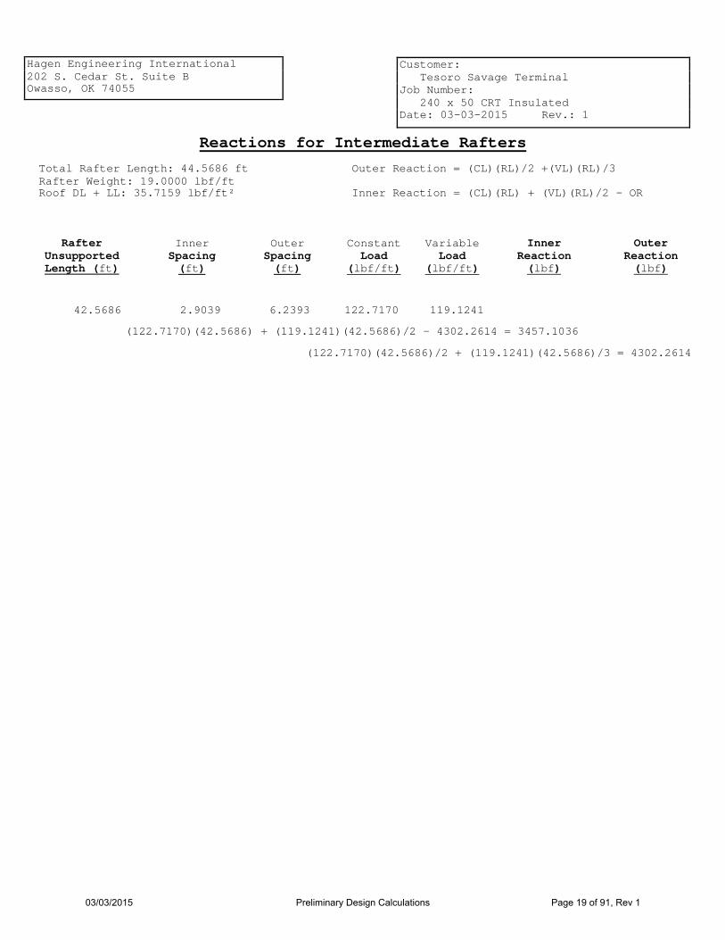
Hagen Engineering International 202 S. Cedar St. Suite B Owasso, OK 74055
Customer: Tesoro Savage Terminal Job Number: 240 x 50 CRT Insulated Date: 03-03-2015 Rev.: 1
Reactions for Intermediate Rafters
Total Rafter Length: 44.5686 ft Rafter Weight: 19.0000 lbf/ft Roof DL + LL: 35.7159 lbf/ft²
Outer Reaction = (CL)(RL)/2 +(VL)(RL)/3 Inner Reaction = (CL)(RL) + (VL)(RL)/2 - OR
Outer Reaction (lbf)
Outer Spacing (ft)
Inner Reaction (lbf)
Inner Spacing (ft)
Rafter Unsupported Length (ft)
Constant Load
(lbf/ft)
Variable Load
(lbf/ft)
6.2393 2.9039 42.5686 122.7170 119.1241
(122.7170)(42.5686)/2 + (119.1241)(42.5686)/3 = 4302.2614
(122.7170)(42.5686) + (119.1241)(42.5686)/2 - 4302.2614 = 3457.1036
03/03/2015 Preliminary Design Calculations Page 19 of 91, Rev 1

Hagen Engineering International 202 S. Cedar St. Suite B Owasso, OK 74055
Customer: Tesoro Savage Terminal Job Number: 240 x 50 CRT Insulated Date: 03-03-2015 Rev.: 1
Reactions for Outer Rafters
Total Rafter Length: 42.6031 ft Rafter Weight: 16.0000 lbf/ft Roof DL + LL: 35.7159 lbf/ft²
Outer Reaction = (CL)(RL)/2 +(VL)(RL)/3 Inner Reaction = (CL)(RL) + (VL)(RL)/2 - OR
Outer Reaction (lbf)
Inner Spacing (ft)
Inner Reaction (lbf)
Outer Spacing (ft)
Rafter Unsupported Length (ft)
Constant Load
(lbf/ft)
Variable Load
(lbf/ft)
3.1300 4.7124 40.3745 127.7898 56.5171
(127.7898)(40.3745)/2 + (56.5171)(40.3745)/3 = 3340.3440
(127.7898)(40.3745) + (56.5171)(40.3745)/2 - 3340.3440 = 2960.0353
3.1106 4.7124 40.8698 127.0965 57.2104
(127.0965)(40.8698) + (57.2104)(40.8698)/2 - 3376.5943 = 2986.8986
(127.0965)(40.8698)/2 + (57.2104)(40.8698)/3 = 3376.5943
3.0961 41.2378 4.7124 126.5813 57.7256
(126.5813)(41.2378) + (57.7256)(41.2378)/2 - 3403.4624 = 3006.7160
(126.5813)(41.2378)/2 + (57.7256)(41.2378)/3 = 3403.4624
3.0866 41.4816 4.7124 126.2400 58.0669
(126.2400)(41.4816) + (58.0669)(41.4816)/2 - 3421.2245 = 3019.7730
(126.2400)(41.4816)/2 + (58.0669)(41.4816)/3 = 3421.2245
3.0818 41.6031 4.7124 126.0700 58.2369
(126.0700)(41.6031) + (58.2369)(41.6031)/2 - 3430.0609 = 3026.2556
(126.0700)(41.6031)/2 + (58.2369)(41.6031)/3 = 3430.0609
03/03/2015 Preliminary Design Calculations Page 20 of 91, Rev 1

Hagen Engineering International 202 S. Cedar St. Suite B Owasso, OK 74055
Customer: Tesoro Savage Terminal Job Number: 240 x 50 CRT Insulated Date: 03-03-2015 Rev.: 1
Loadings and Moments for Intermediate Girders
Total Girder Length: 30.6147 ft Girder Weight: 46.0000 lbf/ft
Load on Column (lbf)
Bending Moment (ft-lb)
Distance from Girder Centerline to Load Centerline (ft)
Load on Girder (lbf) Description
704.14
5389.24
1408.28 Girder
(46.0000)(30.6147)²/8 =
3476.10 13.6335 3476.10 Intermediate Rafter
5818.48 (3476.1036)(30.6147/2 - 13.6335) =
3476.10 10.4224 3476.10 Intermediate Rafter
(3476.1036)(30.6147/2 - 10.4224) = 16980.41
3476.10 7.3508 3476.10 Intermediate Rafter
(3476.1036)(30.6147/2 - 7.3508) = 27657.60
3476.10 4.3739 3476.10 Intermediate Rafter
(3476.1036)(30.6147/2 - 4.3739) = 38005.64
3476.10 1.4520 3476.10 Intermediate Rafter
(3476.1036)(30.6147/2 - 1.4520) = 48162.68
2487.53 12.5446 2487.53 Inner Rafter
(2487.5258)(30.6147/2 - 12.5446) = 6872.40
2337.96 7.3508 2337.96 Inner Rafter
(2337.9586)(30.6147/2 - 7.3508) = 18601.96
2268.38 2.4222 2268.38 Inner Rafter
(2268.3846)(30.6147/2 - 2.4222) = 29228.51
50357.05
196716.92 Total: 25178.52
Total load on Column:
03/03/2015 Preliminary Design Calculations Page 21 of 91, Rev 1

Hagen Engineering International 202 S. Cedar St. Suite B Owasso, OK 74055
Customer: Tesoro Savage Terminal Job Number: 240 x 50 CRT Insulated Date: 03-03-2015 Rev.: 1
Loadings and Moments for Outer Girders
Total Girder Length: 31.2145 ft Girder Weight: 46.0000 lbf/ft
Load on Column (lbf)
Bending Moment (ft-lb)
Distance from Girder Centerline to Load Centerline (ft)
Load on Girder (lbf) Description
717.93
5602.47
1435.86 Girder
(46.0000)(31.2145)²/8 =
2995.69 14.0117 2995.69 Outer Rafter
4779.76 (2995.6918)(31.2145/2 - 14.0117) =
3014.63 10.8527 3014.63 Outer Rafter
(3014.6315)(31.2145/2 - 10.8527) = 14333.07
3028.56 7.7279 3028.56 Outer Rafter
(3028.5597)(31.2145/2 - 7.7279) = 23862.97
3037.72 4.6272 3037.72 Outer Rafter
(3037.7159)(31.2145/2 - 4.6272) = 33354.21
3042.26 1.5408 3042.26 Outer Rafter
(3042.2556)(31.2145/2 - 1.5408) = 42793.63
4321.26 12.4273 4321.26 Intermediate Rafter
(4321.2614)(31.2145/2 - 12.4273) = 13741.33
4321.26 6.1752 4321.26 Intermediate Rafter
(4321.2614)(31.2145/2 - 6.1752) = 40758.43
2160.63 0.0000 4321.26 Intermediate Rafter
(4321.2614)(31.2145/4) = 33721.45
53279.88
212947.32 Total: 26639.94
Total load on Column:
03/03/2015 Preliminary Design Calculations Page 22 of 91, Rev 1

Hagen Engineering International 202 S. Cedar St. Suite B Owasso, OK 74055
Customer: Tesoro Savage Terminal Job Number: 240 x 50 CRT Insulated Date: 03-03-2015 Rev.: 1
Inner Intermediate Girder for Three-Span System Girder description: W18x 46 Quantity (Q): 8 Material grade: A992-GR50 Yield strength (Fy) = 50000 psi Corrosion allowance (CA) = 0.0000 in
Girder dimensions: Flange width (bf) = 6.0600 in Flange thickness (tf) = 0.6050 in Beam Depth (d) = 18.1000 in Web thickness (tw) = 0.3600 in
Minimum thickness per 5.10.2.4 = 0.1700 in
I = 712.0000 in^4 Sx = 78.8000 in³ Area (A) = 13.5000 in² Radius of Gyration (r) = 7.2500 in
Girder length: Distance from tank centerline to column centerline (Co) = 40.0000 ft Girder length (L) = 2(Co)*sin(360/(2Q) = 2 * (40.0000) * sin(360/(2 * 8)) = 30.6147 ft Girder unsupported length L1 = 6.2393 ft L/r = 12 * 30.6147/7.2500 = 10.3271
Bending Moment due to rafter loads and girder weight: M = 196716.9169 ft-lb
Allowable bending moment:
Per AISC360-10: Allowable Flexure Strength (Mc) = 209739.9815 ft-lb
Per AISC360-10: Allowable Flexure Strength (Mc) = 209739.9815 ft-lb
03/03/2015 Preliminary Design Calculations Page 23 of 91, Rev 1
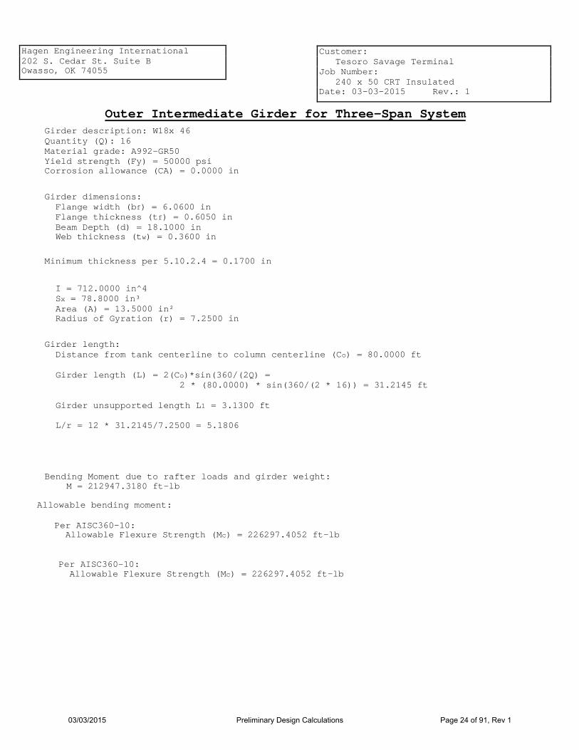
Hagen Engineering International 202 S. Cedar St. Suite B Owasso, OK 74055
Customer: Tesoro Savage Terminal Job Number: 240 x 50 CRT Insulated Date: 03-03-2015 Rev.: 1
Outer Intermediate Girder for Three-Span System Girder description: W18x 46 Quantity (Q): 16 Material grade: A992-GR50 Yield strength (Fy) = 50000 psi Corrosion allowance (CA) = 0.0000 in
Girder dimensions: Flange width (bf) = 6.0600 in Flange thickness (tf) = 0.6050 in Beam Depth (d) = 18.1000 in Web thickness (tw) = 0.3600 in
Minimum thickness per 5.10.2.4 = 0.1700 in
I = 712.0000 in^4 Sx = 78.8000 in³ Area (A) = 13.5000 in² Radius of Gyration (r) = 7.2500 in
Girder length: Distance from tank centerline to column centerline (Co) = 80.0000 ft Girder length (L) = 2(Co)*sin(360/(2Q) = 2 * (80.0000) * sin(360/(2 * 16)) = 31.2145 ft Girder unsupported length L1 = 3.1300 ft L/r = 12 * 31.2145/7.2500 = 5.1806
Bending Moment due to rafter loads and girder weight: M = 212947.3180 ft-lb
Allowable bending moment:
Per AISC360-10: Allowable Flexure Strength (Mc) = 226297.4052 ft-lb
Per AISC360-10: Allowable Flexure Strength (Mc) = 226297.4052 ft-lb
03/03/2015 Preliminary Design Calculations Page 24 of 91, Rev 1

Hagen Engineering International 202 S. Cedar St. Suite B Owasso, OK 74055
Customer: Tesoro Savage Terminal Job Number: 240 x 50 CRT Insulated Date: 03-03-2015 Rev.: 1
Inner Rafter for Three-Span System for Unbalanced Snow Load
Rafter description: W10x 12 Quantity (Q): 48 Material grade: A992-GR50 Yield strength (Fy) = 50000.0000 psi Corrosion allowance (CA) = 0.0000 in
Rafter dimensions: Flange width (bf) = 3.9600 in Flange thickness (tf) = 0.2100 in Beam Depth (d) = 9.8700 in Web thickness (tw) = 0.1900 in
Minimum thickness per 5.10.2.4 = 0.1700 in
I = 53.8000 in^4 Sx = 10.9000 in³ Area (A) = 3.5400 in² Radius of Gyration (r) = 3.9000 in
Spacing and lengths: Distance from tank centerline to inner edge of rafter (Di) = 3.5000 ft Distance from tank centerline to outer edge of rafter (Do) = 39.0263 ft Inner spacing (Si) = 2πDi/Q = 2π(3.5000/48) = 0.4581 ft Outer spacing (So) = 2πDo/Q = 2π(39.0263/48) = 5.1085 ft Rafter length (L) = (Do - Di)/cos(3.5763) = (39.0263 - 3.5000)/cos(3.5763) = 35.5956 ft
For Inner Rafter for Three-Span System rafters, (2) lateral bracing is required equal spaced.
L1 = L/3 = 35.5956/3 = 11.8652 ft
L/r = 12 * 35.5956/3.9000 = 109.5250
03/03/2015 Preliminary Design Calculations Page 25 of 91, Rev 1

Hagen Engineering International 202 S. Cedar St. Suite B Owasso, OK 74055
Customer: Tesoro Savage Terminal Job Number: 240 x 50 CRT Insulated Date: 03-03-2015 Rev.: 1
For dead load only:
Rafter load (Rw) = 12.0000 lbf/ft Dead load (DL) = 8.4375 lbf/ft² Constant load (CL) = (Si)(DL) + Rw = (0.4581)(8.4375) + 12.0000 = 15.8656 lbf/ft Variable load (VL) = (So - Si)(DL) = (5.1085 - 0.4581)(8.4375) = 39.2376 lbf/ft
Determine location (x) where shear = 0 and calculate moment and stress
(VL/2L)x² + (CL)x - (CLL/2 + VLL/6) = 0 [39.2376/(2*35.5956)x² + (15.8656)x - (15.8656*35.5956/2 + 39.2376*35.5956/6) = 0 (0.5512)x² + (15.8656)x - (515.1546) = 0 therefore x = 19.3981 ft M = (CL)(x)(L - x)/2 + (VL)(x)(L² - x²)/(6L) = (15.8656)(19.3981)(35.5956 - 19.3981)/2 + (39.2376)(19.3981)(35.5956² - 19.3981²)/(6*35.5956) = 5667.0008 ft-lb
Allowable bending moment:
Per AISC360-10: Allowable Flexure Strength (Mc) = 10024.3703 ft-lb
Determine allowable stress:
(VL/2L)x² + (CL)x - (CLL/2 + VLL/6) = 0 [166.0926/(2*35.5956)x² + (28.3632)x - (28.3632*35.5956/2 + 166.0926*35.5956/6) = 0 (2.3330)x² + (28.3632)x - (1490.1643) = 0 therefore x = 19.9151 ft M = (CL)(x)(L - x)/2 + (VL)(x)(L² - x²)/(6L) = (28.3632)(19.9151)(35.5956 - 19.9151)/2 + (166.0926)(19.9151)(35.5956² - 19.9151²)/(6*35.5956) = 17909.6235 ft-lb
Determine location (x) where shear = 0 and calculate moment and stress
Rafter load (Rw) = 12.0000 lbf/ft Dead load + Live load per App. R (DL) = 35.7159 lbf/ft² Constant load (CL) = (Si)(DL) + Rw = (0.4581)(35.7159) + 12.0000 = 28.3632 lbf/ft Variable load (VL) = (So - Si)(DL) = (5.1085 - 0.4581)(35.7159) = 166.0926 lbf/ft
For dead load + live load:
Per 5.10.4.3 the roof provides lateral support to the rafters.
03/03/2015 Preliminary Design Calculations Page 26 of 91, Rev 1

Hagen Engineering International 202 S. Cedar St. Suite B Owasso, OK 74055
Customer: Tesoro Savage Terminal Job Number: 240 x 50 CRT Insulated Date: 03-03-2015 Rev.: 1
Per AISC360-10: Allowable Flexure Strength (Mc) = 31437.1257 ft-lb
Determine reaction at end of rafters: At outer end: Ro = CLL/2 + VLL/3 = (28.3632)(35.5956)/2 + (166.0926)(35.5956)/3 = 2475.5258 lbf Ri = CLL + VLL/2 - Ro = (28.3632)(35.5956) + (166.0926)(35.5956)/2 - 2475.5258 = 1490.1643 lbf
03/03/2015 Preliminary Design Calculations Page 27 of 91, Rev 1

Hagen Engineering International 202 S. Cedar St. Suite B Owasso, OK 74055
Customer: Tesoro Savage Terminal Job Number: 240 x 50 CRT Insulated Date: 03-03-2015 Rev.: 1
Intermediate Rafter for Three-Span System for Unbalanced Snow Load
Rafter description: W12x 19 Quantity (Q): 80 Material grade: A992-GR50 Yield strength (Fy) = 50000.0000 psi Corrosion allowance (CA) = 0.0000 in
Rafter dimensions: Flange width (bf) = 4.0100 in Flange thickness (tf) = 0.3500 in Beam Depth (d) = 12.2000 in Web thickness (tw) = 0.2350 in
Minimum thickness per 5.10.2.4 = 0.1700 in
I = 130.0000 in^4 Sx = 21.3000 in³ Area (A) = 5.5700 in² Radius of Gyration (r) = 4.8200 in
Spacing and lengths: Distance from tank centerline to inner edge of rafter (Di) = 36.9552 ft Distance from tank centerline to outer edge of rafter (Do) = 79.4409 ft Inner spacing (Si) = 2πDi/Q = 2π(36.9552/80) = 3.1416 ft Outer spacing (So) = 2πDo/Q = 2π(79.4409/80) = 6.2393 ft Rafter length (L) = (Do - Di)/cos(3.5763) = (79.4409 - 36.9552)/cos(3.5763) = 42.5686 ft
For Intermediate Rafter for Three-Span System rafters, (2) lateral bracing is required equal spaced.
L1 = L/3 = 42.5686/3 = 14.1895 ft
L/r = 12 * 42.5686/4.8200 = 105.9799
03/03/2015 Preliminary Design Calculations Page 28 of 91, Rev 1

Hagen Engineering International 202 S. Cedar St. Suite B Owasso, OK 74055
Customer: Tesoro Savage Terminal Job Number: 240 x 50 CRT Insulated Date: 03-03-2015 Rev.: 1
For dead load only:
Rafter load (Rw) = 19.0000 lbf/ft Dead load (DL) = 8.4375 lbf/ft² Constant load (CL) = (Si)(DL) + Rw = (3.1416)(8.4375) + 19.0000 = 45.5072 lbf/ft Variable load (VL) = (So - Si)(DL) = (6.2393 - 3.1416)(8.4375) = 26.1367 lbf/ft
Determine location (x) where shear = 0 and calculate moment and stress
(VL/2L)x² + (CL)x - (CLL/2 + VLL/6) = 0 [26.1367/(2*42.5686)x² + (45.5072)x - (45.5072*42.5686/2 + 26.1367*42.5686/6) = 0 (0.3070)x² + (45.5072)x - (1154.0219) = 0 therefore x = 22.0725 ft M = (CL)(x)(L - x)/2 + (VL)(x)(L² - x²)/(6L) = (45.5072)(22.0725)(42.5686 - 22.0725)/2 + (26.1367)(22.0725)(42.5686² - 22.0725²)/(6*42.5686) = 13286.2704 ft-lb
Allowable bending moment:
Per AISC360-10: Allowable Flexure Strength (Mc) = 17330.4213 ft-lb
Determine allowable stress:
(VL/2L)x² + (CL)x - (CLL/2 + VLL/6) = 0 [110.6364/(2*42.5686)x² + (131.2048)x - (131.2048*42.5686/2 + 110.6364*42.5686/6) = 0 (1.2995)x² + (131.2048)x - (3577.5409) = 0 therefore x = 22.3288 ft M = (CL)(x)(L - x)/2 + (VL)(x)(L² - x²)/(6L) = (131.2048)(22.3288)(42.5686 - 22.3288)/2 + (110.6364)(22.3288)(42.5686² - 22.3288²)/(6*42.5686) = 42352.1637 ft-lb
Determine location (x) where shear = 0 and calculate moment and stress
Rafter load (Rw) = 19.0000 lbf/ft Dead load + Live load per App. R (DL) = 35.7159 lbf/ft² Constant load (CL) = (Si)(DL) + Rw = (3.1416)(35.7159) + 19.0000 = 131.2048 lbf/ft Variable load (VL) = (So - Si)(DL) = (6.2393 - 3.1416)(35.7159) = 110.6364 lbf/ft
For dead load + live load:
Per 5.10.4.3 the roof provides lateral support to the rafters.
03/03/2015 Preliminary Design Calculations Page 29 of 91, Rev 1

Hagen Engineering International 202 S. Cedar St. Suite B Owasso, OK 74055
Customer: Tesoro Savage Terminal Job Number: 240 x 50 CRT Insulated Date: 03-03-2015 Rev.: 1
Per AISC360-10: Allowable Flexure Strength (Mc) = 61626.7465 ft-lb
Determine reaction at end of rafters: At outer end: Ro = CLL/2 + VLL/3 = (131.2048)(42.5686)/2 + (110.6364)(42.5686)/3 = 4362.4801 lbf Ri = CLL + VLL/2 - Ro = (131.2048)(42.5686) + (110.6364)(42.5686)/2 - 4362.4801 = 3577.5409 lbf
03/03/2015 Preliminary Design Calculations Page 30 of 91, Rev 1

Hagen Engineering International 202 S. Cedar St. Suite B Owasso, OK 74055
Customer: Tesoro Savage Terminal Job Number: 240 x 50 CRT Insulated Date: 03-03-2015 Rev.: 1
Outer Rafter for Three-Span System for Unbalanced Snow Load
Rafter description: W12x 16 Quantity (Q): 160 Material grade: A992-GR50 Yield strength (Fy) = 50000.0000 psi Corrosion allowance (CA) = 0.0000 in
Rafter dimensions: Flange width (bf) = 3.9900 in Flange thickness (tf) = 0.2650 in Beam Depth (d) = 12.0000 in Web thickness (tw) = 0.2200 in
Minimum thickness per 5.10.2.4 = 0.1700 in
I = 103.0000 in^4 Sx = 17.1000 in³ Area (A) = 4.7100 in² Radius of Gyration (r) = 4.6700 in
Spacing and lengths: Distance from tank centerline to inner edge of rafter (Di) = 78.4779 ft Distance from tank centerline to outer edge of rafter (Do) = 120.0000 ft Inner spacing (Si) = 2πDi/Q = 2π(78.4779/160) = 3.0818 ft Outer spacing (So) = 2πDo/Q = 2π(120.0000/160) = 4.7124 ft Rafter length (L) = (Do - Di)/cos(3.5763) = (120.0000 - 78.4779)/cos(3.5763) = 41.6031 ft
For Outer Rafter for Three-Span System rafters, (2) lateral bracing is required equal spaced.
L1 = L/3 = 41.6031/3 = 13.8677 ft
L/r = 12 * 41.6031/4.6700 = 106.9030
03/03/2015 Preliminary Design Calculations Page 31 of 91, Rev 1

Hagen Engineering International 202 S. Cedar St. Suite B Owasso, OK 74055
Customer: Tesoro Savage Terminal Job Number: 240 x 50 CRT Insulated Date: 03-03-2015 Rev.: 1
For dead load only:
Rafter load (Rw) = 16.0000 lbf/ft Dead load (DL) = 8.4375 lbf/ft² Constant load (CL) = (Si)(DL) + Rw = (3.0818)(8.4375) + 16.0000 = 42.0029 lbf/ft Variable load (VL) = (So - Si)(DL) = (4.7124 - 3.0818)(8.4375) = 13.7578 lbf/ft
Determine location (x) where shear = 0 and calculate moment and stress
(VL/2L)x² + (CL)x - (CLL/2 + VLL/6) = 0 [13.7578/(2*41.6031)x² + (42.0029)x - (42.0029*41.6031/2 + 13.7578*41.6031/6) = 0 (0.1653)x² + (42.0029)x - (969.1189) = 0 therefore x = 21.2886 ft M = (CL)(x)(L - x)/2 + (VL)(x)(L² - x²)/(6L) = (42.0029)(21.2886)(41.6031 - 21.2886)/2 + (13.7578)(21.2886)(41.6031² - 21.2886²)/(6*41.6031) = 10581.4802 ft-lb
Allowable bending moment:
Per AISC360-10: Allowable Flexure Strength (Mc) = 12405.6104 ft-lb
Determine allowable stress:
(VL/2L)x² + (CL)x - (CLL/2 + VLL/6) = 0 [58.2369/(2*41.6031)x² + (126.0700)x - (126.0700*41.6031/2 + 58.2369*41.6031/6) = 0 (0.6999)x² + (126.0700)x - (3026.2556) = 0 therefore x = 21.4501 ft M = (CL)(x)(L - x)/2 + (VL)(x)(L² - x²)/(6L) = (126.0700)(21.4501)(41.6031 - 21.4501)/2 + (58.2369)(21.4501)(41.6031² - 21.4501²)/(6*41.6031) = 33608.0934 ft-lb
Determine location (x) where shear = 0 and calculate moment and stress
Rafter load (Rw) = 16.0000 lbf/ft Dead load + Live load per App. R (DL) = 35.7159 lbf/ft² Constant load (CL) = (Si)(DL) + Rw = (3.0818)(35.7159) + 16.0000 = 126.0700 lbf/ft Variable load (VL) = (So - Si)(DL) = (4.7124 - 3.0818)(35.7159) = 58.2369 lbf/ft
For dead load + live load:
Per 5.10.4.3 the roof provides lateral support to the rafters.
03/03/2015 Preliminary Design Calculations Page 32 of 91, Rev 1

Hagen Engineering International 202 S. Cedar St. Suite B Owasso, OK 74055
Customer: Tesoro Savage Terminal Job Number: 240 x 50 CRT Insulated Date: 03-03-2015 Rev.: 1
Per AISC360-10: Allowable Flexure Strength (Mc) = 50149.7006 ft-lb
Determine reaction at end of rafters: At outer end: Ro = CLL/2 + VLL/3 = (126.0700)(41.6031)/2 + (58.2369)(41.6031)/3 = 3430.0609 lbf Ri = CLL + VLL/2 - Ro = (126.0700)(41.6031) + (58.2369)(41.6031)/2 - 3430.0609 = 3026.2556 lbf
03/03/2015 Preliminary Design Calculations Page 33 of 91, Rev 1

Hagen Engineering International 202 S. Cedar St. Suite B Owasso, OK 74055
Customer: Tesoro Savage Terminal Job Number: 240 x 50 CRT Insulated Date: 03-03-2015 Rev.: 1
Inner Rafter for Three-Span System
Rafter description: W10x 12 Quantity (Q): 48 Material grade: A992-GR50 Yield strength (Fy) = 50000.0000 psi Corrosion allowance (CA) = 0.0000 in
Rafter dimensions: Flange width (bf) = 3.9600 in Flange thickness (tf) = 0.2100 in Beam Depth (d) = 9.8700 in Web thickness (tw) = 0.1900 in
Minimum thickness per 5.10.2.4 = 0.1700 in
I = 53.8000 in^4 Sx = 10.9000 in³ Area (A) = 3.5400 in² Radius of Gyration (r) = 3.9000 in
Spacing and lengths: Distance from tank centerline to inner edge of rafter (Di) = 3.5000 ft Distance from tank centerline to outer edge of rafter (Do) = 39.0263 ft Inner spacing (Si) = 2πDi/Q = 2π(3.5000/48) = 0.4581 ft Outer spacing (So) = 2πDo/Q = 2π(39.0263/48) = 5.1085 ft Rafter length (L) = (Do - Di)/cos(3.5763) = (39.0263 - 3.5000)/cos(3.5763) = 35.5956 ft
For Inner Rafter for Three-Span System rafters, (2) lateral bracing is required equal spaced.
L1 = L/3 = 35.5956/3 = 11.8652 ft
L/r = 12 * 35.5956/3.9000 = 109.5250
03/03/2015 Preliminary Design Calculations Page 34 of 91, Rev 1

Hagen Engineering International 202 S. Cedar St. Suite B Owasso, OK 74055
Customer: Tesoro Savage Terminal Job Number: 240 x 50 CRT Insulated Date: 03-03-2015 Rev.: 1
For dead load only:
Rafter load (Rw) = 12.0000 lbf/ft Dead load (DL) = 8.4375 lbf/ft² Constant load (CL) = (Si)(DL) + Rw = (0.4581)(8.4375) + 12.0000 = 15.8656 lbf/ft Variable load (VL) = (So - Si)(DL) = (5.1085 - 0.4581)(8.4375) = 39.2376 lbf/ft
Determine location (x) where shear = 0 and calculate moment and stress
(VL/2L)x² + (CL)x - (CLL/2 + VLL/6) = 0 [39.2376/(2*35.5956)x² + (15.8656)x - (15.8656*35.5956/2 + 39.2376*35.5956/6) = 0 (0.5512)x² + (15.8656)x - (515.1546) = 0 therefore x = 19.3981 ft M = (CL)(x)(L - x)/2 + (VL)(x)(L² - x²)/(6L) = (15.8656)(19.3981)(35.5956 - 19.3981)/2 + (39.2376)(19.3981)(35.5956² - 19.3981²)/(6*35.5956) = 5667.0008 ft-lb
Allowable bending moment:
Per AISC360-10: Allowable Flexure Strength (Mc) = 10024.3703 ft-lb
Determine allowable stress:
(VL/2L)x² + (CL)x - (CLL/2 + VLL/6) = 0 [166.0926/(2*35.5956)x² + (28.3632)x - (28.3632*35.5956/2 + 166.0926*35.5956/6) = 0 (2.3330)x² + (28.3632)x - (1490.1643) = 0 therefore x = 19.9151 ft M = (CL)(x)(L - x)/2 + (VL)(x)(L² - x²)/(6L) = (28.3632)(19.9151)(35.5956 - 19.9151)/2 + (166.0926)(19.9151)(35.5956² - 19.9151²)/(6*35.5956) = 17909.6235 ft-lb
Determine location (x) where shear = 0 and calculate moment and stress
Rafter load (Rw) = 12.0000 lbf/ft Dead load + Live load per App. R (DL) = 35.7159 lbf/ft² Constant load (CL) = (Si)(DL) + Rw = (0.4581)(35.7159) + 12.0000 = 28.3632 lbf/ft Variable load (VL) = (So - Si)(DL) = (5.1085 - 0.4581)(35.7159) = 166.0926 lbf/ft
For dead load + live load:
Per 5.10.4.3 the roof provides lateral support to the rafters.
03/03/2015 Preliminary Design Calculations Page 35 of 91, Rev 1

Hagen Engineering International 202 S. Cedar St. Suite B Owasso, OK 74055
Customer: Tesoro Savage Terminal Job Number: 240 x 50 CRT Insulated Date: 03-03-2015 Rev.: 1
Per AISC360-10: Allowable Flexure Strength (Mc) = 31437.1257 ft-lb
Determine reaction at end of rafters: At outer end: Ro = CLL/2 + VLL/3 = (28.3632)(35.5956)/2 + (166.0926)(35.5956)/3 = 2475.5258 lbf Ri = CLL + VLL/2 - Ro = (28.3632)(35.5956) + (166.0926)(35.5956)/2 - 2475.5258 = 1490.1643 lbf
03/03/2015 Preliminary Design Calculations Page 36 of 91, Rev 1

Hagen Engineering International 202 S. Cedar St. Suite B Owasso, OK 74055
Customer: Tesoro Savage Terminal Job Number: 240 x 50 CRT Insulated Date: 03-03-2015 Rev.: 1
Intermediate Rafter for Three-Span System
Rafter description: W12x 19 Quantity (Q): 80 Material grade: A992-GR50 Yield strength (Fy) = 50000.0000 psi Corrosion allowance (CA) = 0.0000 in
Rafter dimensions: Flange width (bf) = 4.0100 in Flange thickness (tf) = 0.3500 in Beam Depth (d) = 12.2000 in Web thickness (tw) = 0.2350 in
Minimum thickness per 5.10.2.4 = 0.1700 in
I = 130.0000 in^4 Sx = 21.3000 in³ Area (A) = 5.5700 in² Radius of Gyration (r) = 4.8200 in
Spacing and lengths: Distance from tank centerline to inner edge of rafter (Di) = 36.9552 ft Distance from tank centerline to outer edge of rafter (Do) = 79.4409 ft Inner spacing (Si) = 2πDi/Q = 2π(36.9552/80) = 3.1416 ft Outer spacing (So) = 2πDo/Q = 2π(79.4409/80) = 6.2393 ft Rafter length (L) = (Do - Di)/cos(3.5763) = (79.4409 - 36.9552)/cos(3.5763) = 42.5686 ft
For Intermediate Rafter for Three-Span System rafters, (2) lateral bracing is required equal spaced.
L1 = L/3 = 42.5686/3 = 14.1895 ft
L/r = 12 * 42.5686/4.8200 = 105.9799
03/03/2015 Preliminary Design Calculations Page 37 of 91, Rev 1
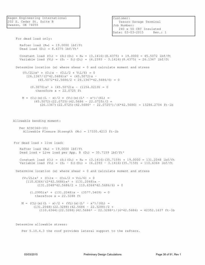
Hagen Engineering International 202 S. Cedar St. Suite B Owasso, OK 74055
Customer: Tesoro Savage Terminal Job Number: 240 x 50 CRT Insulated Date: 03-03-2015 Rev.: 1
For dead load only:
Rafter load (Rw) = 19.0000 lbf/ft Dead load (DL) = 8.4375 lbf/ft² Constant load (CL) = (Si)(DL) + Rw = (3.1416)(8.4375) + 19.0000 = 45.5072 lbf/ft Variable load (VL) = (So - Si)(DL) = (6.2393 - 3.1416)(8.4375) = 26.1367 lbf/ft
Determine location (x) where shear = 0 and calculate moment and stress
(VL/2L)x² + (CL)x - (CLL/2 + VLL/6) = 0 [26.1367/(2*42.5686)x² + (45.5072)x - (45.5072*42.5686/2 + 26.1367*42.5686/6) = 0 (0.3070)x² + (45.5072)x - (1154.0219) = 0 therefore x = 22.0725 ft M = (CL)(x)(L - x)/2 + (VL)(x)(L² - x²)/(6L) = (45.5072)(22.0725)(42.5686 - 22.0725)/2 + (26.1367)(22.0725)(42.5686² - 22.0725²)/(6*42.5686) = 13286.2704 ft-lb
Allowable bending moment:
Per AISC360-10: Allowable Flexure Strength (Mc) = 17330.4213 ft-lb
Determine allowable stress:
(VL/2L)x² + (CL)x - (CLL/2 + VLL/6) = 0 [110.6364/(2*42.5686)x² + (131.2048)x - (131.2048*42.5686/2 + 110.6364*42.5686/6) = 0 (1.2995)x² + (131.2048)x - (3577.5409) = 0 therefore x = 22.3288 ft M = (CL)(x)(L - x)/2 + (VL)(x)(L² - x²)/(6L) = (131.2048)(22.3288)(42.5686 - 22.3288)/2 + (110.6364)(22.3288)(42.5686² - 22.3288²)/(6*42.5686) = 42352.1637 ft-lb
Determine location (x) where shear = 0 and calculate moment and stress
Rafter load (Rw) = 19.0000 lbf/ft Dead load + Live load per App. R (DL) = 35.7159 lbf/ft² Constant load (CL) = (Si)(DL) + Rw = (3.1416)(35.7159) + 19.0000 = 131.2048 lbf/ft Variable load (VL) = (So - Si)(DL) = (6.2393 - 3.1416)(35.7159) = 110.6364 lbf/ft
For dead load + live load:
Per 5.10.4.3 the roof provides lateral support to the rafters.
03/03/2015 Preliminary Design Calculations Page 38 of 91, Rev 1

Hagen Engineering International 202 S. Cedar St. Suite B Owasso, OK 74055
Customer: Tesoro Savage Terminal Job Number: 240 x 50 CRT Insulated Date: 03-03-2015 Rev.: 1
Per AISC360-10: Allowable Flexure Strength (Mc) = 61626.7465 ft-lb
Determine reaction at end of rafters: At outer end: Ro = CLL/2 + VLL/3 = (131.2048)(42.5686)/2 + (110.6364)(42.5686)/3 = 4362.4801 lbf Ri = CLL + VLL/2 - Ro = (131.2048)(42.5686) + (110.6364)(42.5686)/2 - 4362.4801 = 3577.5409 lbf
03/03/2015 Preliminary Design Calculations Page 39 of 91, Rev 1

Hagen Engineering International 202 S. Cedar St. Suite B Owasso, OK 74055
Customer: Tesoro Savage Terminal Job Number: 240 x 50 CRT Insulated Date: 03-03-2015 Rev.: 1
Outer Rafter for Three-Span System
Rafter description: W12x 16 Quantity (Q): 160 Material grade: A992-GR50 Yield strength (Fy) = 50000.0000 psi Corrosion allowance (CA) = 0.0000 in
Rafter dimensions: Flange width (bf) = 3.9900 in Flange thickness (tf) = 0.2650 in Beam Depth (d) = 12.0000 in Web thickness (tw) = 0.2200 in
Minimum thickness per 5.10.2.4 = 0.1700 in
I = 103.0000 in^4 Sx = 17.1000 in³ Area (A) = 4.7100 in² Radius of Gyration (r) = 4.6700 in
Spacing and lengths: Distance from tank centerline to inner edge of rafter (Di) = 78.4779 ft Distance from tank centerline to outer edge of rafter (Do) = 120.0000 ft Inner spacing (Si) = 2πDi/Q = 2π(78.4779/160) = 3.0818 ft Outer spacing (So) = 2πDo/Q = 2π(120.0000/160) = 4.7124 ft Rafter length (L) = (Do - Di)/cos(3.5763) = (120.0000 - 78.4779)/cos(3.5763) = 41.6031 ft
For Outer Rafter for Three-Span System rafters, (2) lateral bracing is required equal spaced.
L1 = L/3 = 41.6031/3 = 13.8677 ft
L/r = 12 * 41.6031/4.6700 = 106.9030
03/03/2015 Preliminary Design Calculations Page 40 of 91, Rev 1

Hagen Engineering International 202 S. Cedar St. Suite B Owasso, OK 74055
Customer: Tesoro Savage Terminal Job Number: 240 x 50 CRT Insulated Date: 03-03-2015 Rev.: 1
For dead load only:
Rafter load (Rw) = 16.0000 lbf/ft Dead load (DL) = 8.4375 lbf/ft² Constant load (CL) = (Si)(DL) + Rw = (3.0818)(8.4375) + 16.0000 = 42.0029 lbf/ft Variable load (VL) = (So - Si)(DL) = (4.7124 - 3.0818)(8.4375) = 13.7578 lbf/ft
Determine location (x) where shear = 0 and calculate moment and stress
(VL/2L)x² + (CL)x - (CLL/2 + VLL/6) = 0 [13.7578/(2*41.6031)x² + (42.0029)x - (42.0029*41.6031/2 + 13.7578*41.6031/6) = 0 (0.1653)x² + (42.0029)x - (969.1189) = 0 therefore x = 21.2886 ft M = (CL)(x)(L - x)/2 + (VL)(x)(L² - x²)/(6L) = (42.0029)(21.2886)(41.6031 - 21.2886)/2 + (13.7578)(21.2886)(41.6031² - 21.2886²)/(6*41.6031) = 10581.4802 ft-lb
Allowable bending moment:
Per AISC360-10: Allowable Flexure Strength (Mc) = 12405.6104 ft-lb
Determine allowable stress:
(VL/2L)x² + (CL)x - (CLL/2 + VLL/6) = 0 [58.2369/(2*41.6031)x² + (126.0700)x - (126.0700*41.6031/2 + 58.2369*41.6031/6) = 0 (0.6999)x² + (126.0700)x - (3026.2556) = 0 therefore x = 21.4501 ft M = (CL)(x)(L - x)/2 + (VL)(x)(L² - x²)/(6L) = (126.0700)(21.4501)(41.6031 - 21.4501)/2 + (58.2369)(21.4501)(41.6031² - 21.4501²)/(6*41.6031) = 33608.0934 ft-lb
Determine location (x) where shear = 0 and calculate moment and stress
Rafter load (Rw) = 16.0000 lbf/ft Dead load + Live load per App. R (DL) = 35.7159 lbf/ft² Constant load (CL) = (Si)(DL) + Rw = (3.0818)(35.7159) + 16.0000 = 126.0700 lbf/ft Variable load (VL) = (So - Si)(DL) = (4.7124 - 3.0818)(35.7159) = 58.2369 lbf/ft
For dead load + live load:
Per 5.10.4.3 the roof provides lateral support to the rafters.
03/03/2015 Preliminary Design Calculations Page 41 of 91, Rev 1
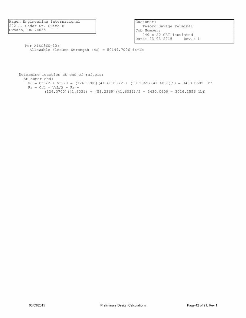
Hagen Engineering International 202 S. Cedar St. Suite B Owasso, OK 74055
Customer: Tesoro Savage Terminal Job Number: 240 x 50 CRT Insulated Date: 03-03-2015 Rev.: 1
Per AISC360-10: Allowable Flexure Strength (Mc) = 50149.7006 ft-lb
Determine reaction at end of rafters: At outer end: Ro = CLL/2 + VLL/3 = (126.0700)(41.6031)/2 + (58.2369)(41.6031)/3 = 3430.0609 lbf Ri = CLL + VLL/2 - Ro = (126.0700)(41.6031) + (58.2369)(41.6031)/2 - 3430.0609 = 3026.2556 lbf
03/03/2015 Preliminary Design Calculations Page 42 of 91, Rev 1

Hagen Engineering International 202 S. Cedar St. Suite B Owasso, OK 74055
Customer: Tesoro Savage Terminal Job Number: 240 x 50 CRT Insulated Date: 03-03-2015 Rev.: 1
ALLOWABLE FLEXURE STRENGTH PER AISC360-10
Inner Intermediate Girder for Three-Span System
Girder description: W18x 46 Quantity (Q): 8 Material grade: Yield strength (Fy) = 50000 psi Corrosion allowance (CA) = 0.0000 in
Girder dimensions: Flange width (bf) = 6.0600 in Flange thickness (tf) = 0.6050 in Beam Depth (d) = 18.1000 in Web thickness (tw) = 0.3600 in
Ix = 712.0000 in^4 Sx = 78.8000 in³ Zx = 90.7000 in³ rx = 7.2500 in Iy = 22.5000 in^4 Sy = 7.4300 in³ Zy = 8.0000 in³ ry = 1.2900 in J = 1.2200 in^4 Cw = 1720.0000 in^6 A = 13.5000 in²
Unsupported Girder length (Lb) = 74.8713 in
Determine allowable stress:
Flange classificati0n (AISC 16.1 B4) b = 3.0300 in b/tf = 5.0083 λp = 0.38√(E/Fy) = 0.38√(28800000.0000/50000.0000) = 9.1200 λr = 1.0√(E/Fy) = 1.0√(28800000.0000/50000.0000) = 24.0000
Flanges are Compact
E = 28800000.0000 psi
03/03/2015 Preliminary Design Calculations Page 43 of 91, Rev 1


Hagen Engineering International 202 S. Cedar St. Suite B Owasso, OK 74055
Customer: Tesoro Savage Terminal Job Number: 240 x 50 CRT Insulated Date: 03-03-2015 Rev.: 1
Lp < Lb ≤ Lr
(F2-2) Mn = Cb Mp - (Mp - 0.7FySx) ( [ 1.0000 4535000.0000 - (4535000.0000 - 0.7 * 50000.0000 * 78.8000)
] [
74.8713 - 54.4896 163.6428 - 54.4896
= 4203189.2296 in-lb (
) ] Lb - Lp = Lr - Lp
)
For dead load + live load: Minimmum Mn = 4203189.2296 in-lb Allowable Flexure Strength = Mc = Mn/Ωb = 4203189.2296/1.67 = 2516879.7782 in-lb = 2516879.7782/12 = 209739.9815 ft-lb
03/03/2015 Preliminary Design Calculations Page 45 of 91, Rev 1

Hagen Engineering International 202 S. Cedar St. Suite B Owasso, OK 74055
Customer: Tesoro Savage Terminal Job Number: 240 x 50 CRT Insulated Date: 03-03-2015 Rev.: 1
ALLOWABLE FLEXURE STRENGTH PER AISC360-10
Outer Intermediate Girder for Three-Span System
Girder description: W18x 46 Quantity (Q): 16 Material grade: Yield strength (Fy) = 50000 psi Corrosion allowance (CA) = 0.0000 in
Girder dimensions: Flange width (bf) = 6.0600 in Flange thickness (tf) = 0.6050 in Beam Depth (d) = 18.1000 in Web thickness (tw) = 0.3600 in
Ix = 712.0000 in^4 Sx = 78.8000 in³ Zx = 90.7000 in³ rx = 7.2500 in Iy = 22.5000 in^4 Sy = 7.4300 in³ Zy = 16.0000 in³ ry = 1.2900 in J = 1.2200 in^4 Cw = 1720.0000 in^6 A = 13.5000 in²
Unsupported Girder length (Lb) = 37.5597 in
Determine allowable stress:
Flange classificati0n (AISC 16.1 B4) b = 3.0300 in b/tf = 5.0083 λp = 0.38√(E/Fy) = 0.38√(28800000.0000/50000.0000) = 9.1200 λr = 1.0√(E/Fy) = 1.0√(28800000.0000/50000.0000) = 24.0000
Flanges are Compact
E = 28800000.0000 psi
03/03/2015 Preliminary Design Calculations Page 46 of 91, Rev 1

Hagen Engineering International 202 S. Cedar St. Suite B Owasso, OK 74055
Customer: Tesoro Savage Terminal Job Number: 240 x 50 CRT Insulated Date: 03-03-2015 Rev.: 1
Web classification (AISC 16.1 B4) h/tw = 46.9167 λp = 3.76√(E/Fy) = 3.76√(28800000.0000/50000.0000) = 90.2400 λr = 5.70√(E/Fy) = 5.70√(28800000.0000/50000.0000) = 136.8000
Webs are Compact
(Per AISC 16.1 F1 for ASD) Ωb = 1.67
Lateral Torsional Buckling: (F2-5) Lp = 1.76ry E = 1.76 * 1.2900 Fy √ 28800000.0000
50000.0000 √ = 54.4896 in
Yielding: (F2-1) Mn = Mp = Fy * Zx = 50000.0000 * 90.7000 = 4535000.0000 in-lb
The limit state of lateral-torsional buckling does not apply per F2.2(a).
For dead load + live load: Minimmum Mn = 4535000.0000 in-lb Allowable Flexure Strength = Mc = Mn/Ωb = 4535000.0000/1.67 = 2715568.8623 in-lb = 2715568.8623/12 = 226297.4052 ft-lb
03/03/2015 Preliminary Design Calculations Page 47 of 91, Rev 1
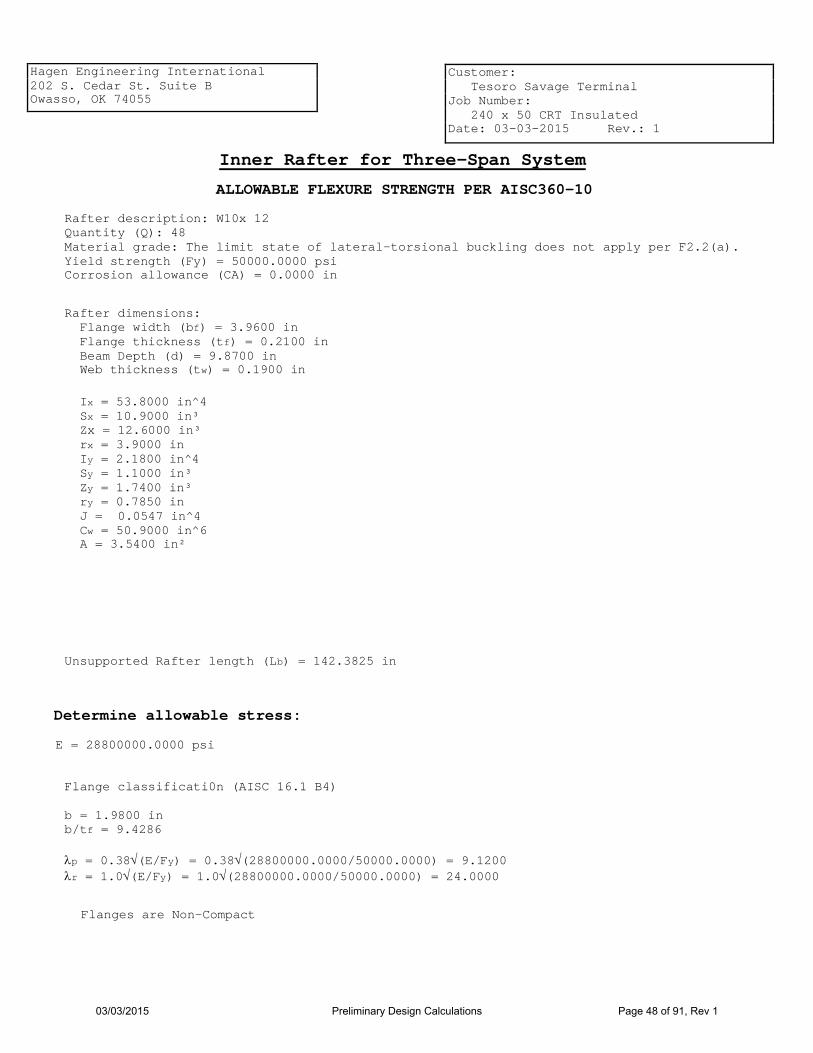
Hagen Engineering International 202 S. Cedar St. Suite B Owasso, OK 74055
Customer: Tesoro Savage Terminal Job Number: 240 x 50 CRT Insulated Date: 03-03-2015 Rev.: 1
ALLOWABLE FLEXURE STRENGTH PER AISC360-10
Inner Rafter for Three-Span System
Rafter description: W10x 12 Quantity (Q): 48 Material grade: The limit state of lateral-torsional buckling does not apply per F2.2(a). Yield strength (Fy) = 50000.0000 psi Corrosion allowance (CA) = 0.0000 in
Rafter dimensions: Flange width (bf) = 3.9600 in Flange thickness (tf) = 0.2100 in Beam Depth (d) = 9.8700 in Web thickness (tw) = 0.1900 in
Ix = 53.8000 in^4 Sx = 10.9000 in³ Zx = 12.6000 in³ rx = 3.9000 in Iy = 2.1800 in^4 Sy = 1.1000 in³ Zy = 1.7400 in³ ry = 0.7850 in J = 0.0547 in^4 Cw = 50.9000 in^6 A = 3.5400 in²
Unsupported Rafter length (Lb) = 142.3825 in
Determine allowable stress:
Flange classificati0n (AISC 16.1 B4) b = 1.9800 in b/tf = 9.4286 λp = 0.38√(E/Fy) = 0.38√(28800000.0000/50000.0000) = 9.1200 λr = 1.0√(E/Fy) = 1.0√(28800000.0000/50000.0000) = 24.0000
Flanges are Non-Compact
E = 28800000.0000 psi
03/03/2015 Preliminary Design Calculations Page 48 of 91, Rev 1

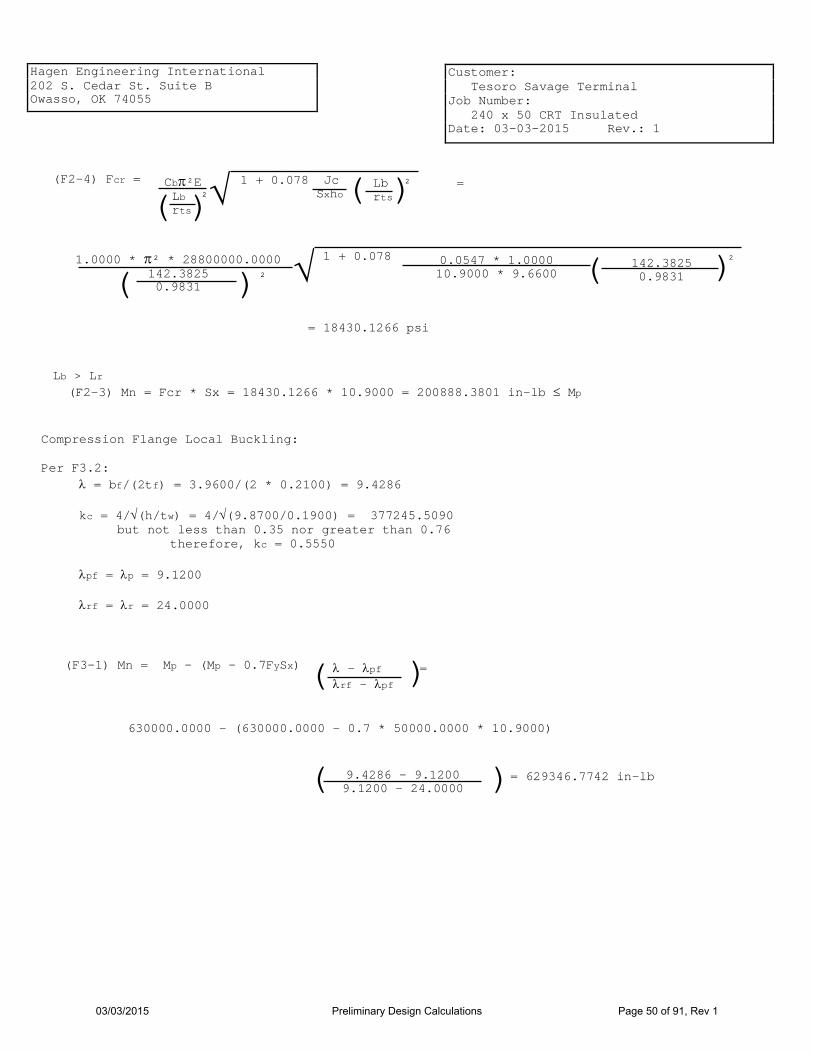
Hagen Engineering International 202 S. Cedar St. Suite B Owasso, OK 74055
Customer: Tesoro Savage Terminal Job Number: 240 x 50 CRT Insulated Date: 03-03-2015 Rev.: 1
(F2-4) Fcr = √
(
( (
1.0000 * π² * 28800000.0000 142.3825 0.9831
1 + 0.078 0.0547 * 1.0000 10.9000 * 9.6600
142.3825 0.9831 √ (
² ²
= 18430.1266 psi
Lb > Lr (F2-3) Mn = Fcr * Sx = 18430.1266 * 10.9000 = 200888.3801 in-lb ≤ Mp
) )
) ) Cbπ²E Lb ² rts
1 + 0.078 Jc Sxho
Lb ² = rts
Compression Flange Local Buckling: Per F3.2: λ = bf/(2tf) = 3.9600/(2 * 0.2100) = 9.4286 kc = 4/√(h/tw) = 4/√(9.8700/0.1900) = 377245.5090 but not less than 0.35 nor greater than 0.76 therefore, kc = 0.5550 λpf = λp = 9.1200 λrf = λr = 24.0000
(F3-1) Mn = Mp - (Mp - 0.7FySx) ( 630000.0000 - (630000.0000 - 0.7 * 50000.0000 * 10.9000)
9.4286 - 9.1200 9.1200 - 24.0000
= 629346.7742 in-lb (
)
)
λ - λpf = λrf - λpf
03/03/2015 Preliminary Design Calculations Page 50 of 91, Rev 1

Hagen Engineering International 202 S. Cedar St. Suite B Owasso, OK 74055
Customer: Tesoro Savage Terminal Job Number: 240 x 50 CRT Insulated Date: 03-03-2015 Rev.: 1
For dead load only: Minimmum Mn = 200888.3801 in-lb Allowable Flexure Strength = Mc = Mn/Ωb = 200888.3801/1.67 = 120292.4432 in-lb = 120292.4432/12 = 10024.3703 ft-lb
For dead load + live load: Minimmum Mn = 630000.0000 in-lb Allowable Flexure Strength = Mc = Mn/Ωb = 630000.0000/1.67 = 377245.5090 in-lb = 377245.5090/12 = 31437.1257 ft-lb
The limit state of lateral-torsional buckling does not apply per F2.2(a).
Per 5.10.4.3 the roof provides lateral support to the rafters.
03/03/2015 Preliminary Design Calculations Page 51 of 91, Rev 1
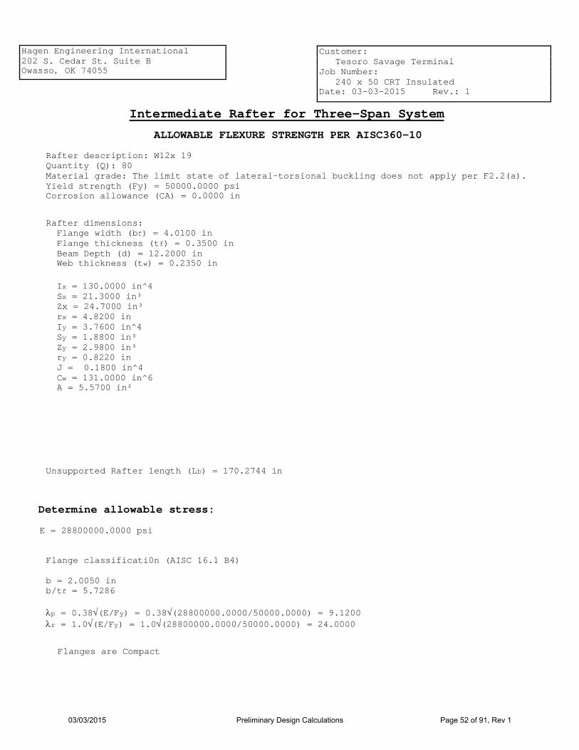
Hagen Engineering International 202 S. Cedar St. Suite B Owasso, OK 74055
Customer: Tesoro Savage Terminal Job Number: 240 x 50 CRT Insulated Date: 03-03-2015 Rev.: 1
ALLOWABLE FLEXURE STRENGTH PER AISC360-10
Intermediate Rafter for Three-Span System
Rafter description: W12x 19 Quantity (Q): 80 Material grade: The limit state of lateral-torsional buckling does not apply per F2.2(a). Yield strength (Fy) = 50000.0000 psi Corrosion allowance (CA) = 0.0000 in
Rafter dimensions: Flange width (bf) = 4.0100 in Flange thickness (tf) = 0.3500 in Beam Depth (d) = 12.2000 in Web thickness (tw) = 0.2350 in
Ix = 130.0000 in^4 Sx = 21.3000 in³ Zx = 24.7000 in³ rx = 4.8200 in Iy = 3.7600 in^4 Sy = 1.8800 in³ Zy = 2.9800 in³ ry = 0.8220 in J = 0.1800 in^4 Cw = 131.0000 in^6 A = 5.5700 in²
Unsupported Rafter length (Lb) = 170.2744 in
Determine allowable stress:
Flange classificati0n (AISC 16.1 B4) b = 2.0050 in b/tf = 5.7286 λp = 0.38√(E/Fy) = 0.38√(28800000.0000/50000.0000) = 9.1200 λr = 1.0√(E/Fy) = 1.0√(28800000.0000/50000.0000) = 24.0000
Flanges are Compact
E = 28800000.0000 psi
03/03/2015 Preliminary Design Calculations Page 52 of 91, Rev 1


Hagen Engineering International 202 S. Cedar St. Suite B Owasso, OK 74055
Customer: Tesoro Savage Terminal Job Number: 240 x 50 CRT Insulated Date: 03-03-2015 Rev.: 1
(F2-4) Fcr = √
(
( (
1.0000 * π² * 28800000.0000 170.2744 1.0208
1 + 0.078 0.1800 * 1.0000 21.3000 * 11.8500
170.2744 1.0208 √ (
² ²
= 16305.2415 psi
Lb > Lr (F2-3) Mn = Fcr * Sx = 16305.2415 * 21.3000 = 347301.6433 in-lb ≤ Mp
) )
) ) Cbπ²E Lb ² rts
1 + 0.078 Jc Sxho
Lb ² = rts
For dead load only: Minimmum Mn = 347301.6433 in-lb Allowable Flexure Strength = Mc = Mn/Ωb = 347301.6433/1.67 = 207965.0559 in-lb = 207965.0559/12 = 17330.4213 ft-lb
For dead load + live load: Minimmum Mn = 1235000.0000 in-lb Allowable Flexure Strength = Mc = Mn/Ωb = 1235000.0000/1.67 = 739520.9581 in-lb = 739520.9581/12 = 61626.7465 ft-lb
The limit state of lateral-torsional buckling does not apply per F2.2(a).
Per 5.10.4.3 the roof provides lateral support to the rafters.
03/03/2015 Preliminary Design Calculations Page 54 of 91, Rev 1

Hagen Engineering International 202 S. Cedar St. Suite B Owasso, OK 74055
Customer: Tesoro Savage Terminal Job Number: 240 x 50 CRT Insulated Date: 03-03-2015 Rev.: 1
ALLOWABLE FLEXURE STRENGTH PER AISC360-10
Outer Rafter for Three-Span System
Rafter description: W12x 16 Quantity (Q): 160 Material grade: The limit state of lateral-torsional buckling does not apply per F2.2(a). Yield strength (Fy) = 50000.0000 psi Corrosion allowance (CA) = 0.0000 in
Rafter dimensions: Flange width (bf) = 3.9900 in Flange thickness (tf) = 0.2650 in Beam Depth (d) = 12.0000 in Web thickness (tw) = 0.2200 in
Ix = 103.0000 in^4 Sx = 17.1000 in³ Zx = 20.1000 in³ rx = 4.6700 in Iy = 2.8200 in^4 Sy = 1.4100 in³ Zy = 2.2600 in³ ry = 0.7730 in J = 0.1030 in^4 Cw = 96.9000 in^6 A = 4.7100 in²
Unsupported Rafter length (Lb) = 166.4123 in
Determine allowable stress:
Flange classificati0n (AISC 16.1 B4) b = 1.9950 in b/tf = 7.5283 λp = 0.38√(E/Fy) = 0.38√(28800000.0000/50000.0000) = 9.1200 λr = 1.0√(E/Fy) = 1.0√(28800000.0000/50000.0000) = 24.0000
Flanges are Compact
E = 28800000.0000 psi
03/03/2015 Preliminary Design Calculations Page 55 of 91, Rev 1


Hagen Engineering International 202 S. Cedar St. Suite B Owasso, OK 74055
Customer: Tesoro Savage Terminal Job Number: 240 x 50 CRT Insulated Date: 03-03-2015 Rev.: 1
(F2-4) Fcr = √
(
( (
1.0000 * π² * 28800000.0000 166.4123 0.9832
1 + 0.078 0.1030 * 1.0000 17.1000 * 11.7350
166.4123 0.9832 √ (
² ²
= 14538.5049 psi
Lb > Lr (F2-3) Mn = Fcr * Sx = 14538.5049 * 17.1000 = 248608.4333 in-lb ≤ Mp
) )
) ) Cbπ²E Lb ² rts
1 + 0.078 Jc Sxho
Lb ² = rts
For dead load only: Minimmum Mn = 248608.4333 in-lb Allowable Flexure Strength = Mc = Mn/Ωb = 248608.4333/1.67 = 148867.3253 in-lb = 148867.3253/12 = 12405.6104 ft-lb
For dead load + live load: Minimmum Mn = 1005000.0000 in-lb Allowable Flexure Strength = Mc = Mn/Ωb = 1005000.0000/1.67 = 601796.4072 in-lb = 601796.4072/12 = 50149.7006 ft-lb
The limit state of lateral-torsional buckling does not apply per F2.2(a).
Per 5.10.4.3 the roof provides lateral support to the rafters.
03/03/2015 Preliminary Design Calculations Page 57 of 91, Rev 1

Hagen Engineering International 202 S. Cedar St. Suite B Owasso, OK 74055
Customer: Tesoro Savage Terminal Job Number: 240 x 50 CRT Insulated Date: 03-03-2015 Rev.: 1
Intermediate Column for Supported Cone Roof
(16) Columns located on 80.0000 ft Radius
Column description: 10" Std Wt Pipe Material grade: A53-B Yield strength (Fy) = 35000.0000 psi Corrosion allowance (CA) = 0.0000 in
Outside Diameter (Do) = 10.7500 in Wall thickness (tw) = 0.3650 in Mill tolerance (m) = 12.50%
therefore tw = tw(1 - m) = 0.3650(1 - 0.1250) = 0.3194 in
t = tw = 0.3194 in
Pipe Inside Diameter (Di) = Do - 2t = 10.7500 - 2*0.3194 = 10.1113 in Area (A) = π (Do² - Di²)/4 = π(10.7500² - 10.1113²)/4 = 10.4655 in² Radius of Gyration (r) = √(Do² + Di²)/4 = √(10.7500² + 10.1113²)/4 = 3.6895 in Section Modulus (qs) = 0.098175(Do/^4 - d1^4)/Do = 0.098175((10.7500)^4 - (10.1113)^4)/10.7500 = 26.5046 in³
K = 1.00 Calculate column length: Tank Radius (R1) = 120.0000 ft
Column Location Radius (R2) = 80.0000 ft
Bottom with Annular Ring Sloped Up 1.0000 in 120
Roof Rise (L1) = (R1 - R2)tan(0.0624) = (120.0000 - 80.0000)tan(0.0624) = 2.5000 ft
Bottom Slope (L2) = -(R1)(Rise)/Run = -(120.0000)(1.0000)/120.0000 = -1.0000 ft
Tank vertical height (L3) = 50.0000 ft
Rafter depth (L5) = 12.2000 in Girder depth (L6) = 18.1000 in Therefore, L = (L1 + L2 + L3)12 - L5 - L6 = (2.5000 + -1.0000 + 50.0000)12 - 12.2000 - 18.1000 = 585.5750 in
KL/r = (1.00)(585.5750)/3.6895 = 158.7134
For Outer Intermediate Column, KL/r = 158.7
Calculate column load: P (from girder loads) = 53279.8807 lbf
Modulus of Elasticity at 150.0000° (E): 28800000.0000 psi
03/03/2015 Preliminary Design Calculations Page 58 of 91, Rev 1

Hagen Engineering International 202 S. Cedar St. Suite B Owasso, OK 74055
Customer: Tesoro Savage Terminal Job Number: 240 x 50 CRT Insulated Date: 03-03-2015 Rev.: 1
DETERMINE ALLOWABLE LOAD PER AISC 360-10 E3: Ωc = 1.67 V = 4.71√(E/Fy) = 4.71√[(28800000.0000)/35000.0000] = 135.1086
Fe = π²E (KL/r)²
= π²(28800000.0000) (158.7134)²
= 11284.0454 psi
(E3-3) Fcr = 0.877Fe = 0.877 * 11284.0454 = 9896.1078 psi
(E3.1) Pn = FcrA = 9896.1078 * 10.4655 = 103567.9884 lbf Pc = Pn/ΩC = 103567.9884/1.67 = 62016.7595 lbf
For Outer Intermediate Column, load (53279.88) is less than the allowable load (62016.76).
03/03/2015 Preliminary Design Calculations Page 59 of 91, Rev 1

Hagen Engineering International 202 S. Cedar St. Suite B Owasso, OK 74055
Customer: Tesoro Savage Terminal Job Number: 240 x 50 CRT Insulated Date: 03-03-2015 Rev.: 1
Intermediate Column for Supported Cone Roof
(8) Columns located on 40.0000 ft Radius
Column description: 10" Std Wt Pipe Material grade: A53-B Yield strength (Fy) = 35000.0000 psi Corrosion allowance (CA) = 0.0000 in
Outside Diameter (Do) = 10.7500 in Wall thickness (tw) = 0.3650 in Mill tolerance (m) = 12.50%
therefore tw = tw(1 - m) = 0.3650(1 - 0.1250) = 0.3194 in
t = tw = 0.3194 in
Pipe Inside Diameter (Di) = Do - 2t = 10.7500 - 2*0.3194 = 10.1113 in Area (A) = π (Do² - Di²)/4 = π(10.7500² - 10.1113²)/4 = 10.4655 in² Radius of Gyration (r) = √(Do² + Di²)/4 = √(10.7500² + 10.1113²)/4 = 3.6895 in Section Modulus (qs) = 0.098175(Do/^4 - d1^4)/Do = 0.098175((10.7500)^4 - (10.1113)^4)/10.7500 = 26.5046 in³
K = 1.00 Calculate column length: Tank Radius (R1) = 120.0000 ft
Column Location Radius (R2) = 40.0000 ft
Bottom with Annular Ring Sloped Up 1.0000 in 120
Roof Rise (L1) = (R1 - R2)tan(0.0624) = (120.0000 - 40.0000)tan(0.0624) = 5.0000 ft
Bottom Slope (L2) = -(R1)(Rise)/Run = -(120.0000)(1.0000)/120.0000 = -1.0000 ft
Tank vertical height (L3) = 50.0000 ft
Rafter depth (L5) = 12.2000 in Girder depth (L6) = 18.1000 in Therefore, L = (L1 + L2 + L3)12 - L5 - L6 = (5.0000 + -1.0000 + 50.0000)12 - 12.2000 - 18.1000 = 615.5750 in
KL/r = (1.00)(615.5750)/3.6895 = 166.8446
For Inner Intermediate Column, KL/r = 166.8
Calculate column load: P (from girder loads) = 50357.0490 lbf
Modulus of Elasticity at 150.0000° (E): 28800000.0000 psi
03/03/2015 Preliminary Design Calculations Page 60 of 91, Rev 1

Hagen Engineering International 202 S. Cedar St. Suite B Owasso, OK 74055
Customer: Tesoro Savage Terminal Job Number: 240 x 50 CRT Insulated Date: 03-03-2015 Rev.: 1
DETERMINE ALLOWABLE LOAD PER AISC 360-10 E3: Ωc = 1.67 V = 4.71√(E/Fy) = 4.71√[(28800000.0000)/35000.0000] = 135.1086
Fe = π²E (KL/r)²
= π²(28800000.0000) (166.8446)²
= 10210.9919 psi
(E3-3) Fcr = 0.877Fe = 0.877 * 10210.9919 = 8955.0399 psi
(E3.1) Pn = FcrA = 8955.0399 * 10.4655 = 93719.2162 lbf Pc = Pn/ΩC = 93719.2162/1.67 = 56119.2911 lbf
For Inner Intermediate Column, load (50357.05) is less than the allowable load (56119.29).
03/03/2015 Preliminary Design Calculations Page 61 of 91, Rev 1

Hagen Engineering International 202 S. Cedar St. Suite B Owasso, OK 74055
Customer: Tesoro Savage Terminal Job Number: 240 x 50 CRT Insulated Date: 03-03-2015 Rev.: 1
Center Column for Supported Cone Roof Column description: 14" Std Wt Pipe Material grade: A53-B Yield strength (Fy) = 35000.0000 psi Corrosion allowance (CA) = 0.0000 in
Outside Diameter (Do) = 14.0000 in Wall thickness (tw) = 0.3750 in Mill tolerance (m) = 12.50%
therefore tw = tw(1 - m) = 0.3750(1 - 0.1250) = 0.3281 in
t = tw = 0.3281 in
Pipe Inside Diameter (Di) = Do - 2t = 14.0000 - 2*0.3281 = 13.3438 in Area (A) = π (Do² - Di²)/4 = π(14.0000² - 13.3438²)/4 = 14.0934 in² Radius of Gyration (r) = √(Do² + Di²)/4 = √(14.0000² + 13.3438²)/4 = 4.8351 in Section Modulus (qs) = 0.098175(Do/^4 - d1^4)/Do = 0.098175((14.0000)^4 - (13.3438)^4)/14.0000 = 47.0692 in³
K = 1.00 Calculate column length: Tank Radius (R1) = 120.0000 ft
Cap Radius (R2) = 3.5000 ft
Bottom with Annular Ring Sloped Up 1.0000 in 120
Roof Rise (L1) = (R1 - R2)tan(0.0624) = (120.0000 - 3.5000)tan(0.0624) = 7.2813 ft
Bottom Slope (L2) = -(R1)(Rise)/Run = -(120.0000)(1.0000)/120.0000 = -1.0000 ft
Tank vertical height (L3) = 50.0000 ft
Rafter depth (L5) = 9.8700 in Therefore, L = (L1 + L2 + L3)12 - L5 = (7.2813 + -1.0000 + 50.0000)12 - 9.8700 = 663.3800 in
KL/r = (1.00)(663.3800)/4.8351 = 137.2000
For center column, KL/r = 137.2
03/03/2015 Preliminary Design Calculations Page 62 of 91, Rev 1

Hagen Engineering International 202 S. Cedar St. Suite B Owasso, OK 74055
Customer: Tesoro Savage Terminal Job Number: 240 x 50 CRT Insulated Date: 03-03-2015 Rev.: 1
Calculate column load: Quantity of rafters (Q) = 48 Total load from Reactions for Inner Rafters (Ri) = 67877.5041 lbf Rafter extension on cap (L6) = 6.0000 in Rafter weight (Rw) = 12.0000 lbf Roof dead load + live load (DL) = 35.7159 lbf/ft² Weight of cap plate (Cw) = 3496.2470 lbf P = Ri + QRw(L6/12) + πR2²DL + Cw = 67877.5041 + (48)(12.0000)(6.0000/12) + π(3.5000)²(35.7159) + 3496.2470 = 73036.2601 lbf
Modulus of Elasticity at 150.0000° (E): 28800000.0000 psi
DETERMINE ALLOWABLE LOAD PER AISC 360-10 E3: Ωc = 1.67 V = 4.71√(E/Fy) = 4.71√[(28800000.0000)/35000.0000] = 135.1086
Fe = π²E (KL/r)²
= π²(28800000.0000) (137.2000)²
= 15100.2361 psi
(E3-3) Fcr = 0.877Fe = 0.877 * 15100.2361 = 13242.9071 psi
(E3.1) Pn = FcrA = 13242.9071 * 14.0934 = 186638.2285 lbf Pc = Pn/ΩC = 186638.2285/1.67 = 111759.4183 lbf
Load on center column (73036.26) is less than the allowable load (111759.42).
03/03/2015 Preliminary Design Calculations Page 63 of 91, Rev 1

Hagen Engineering International 202 S. Cedar St. Suite B Owasso, OK 74055
Customer: Tesoro Savage Terminal Job Number: 240 x 50 CRT Insulated Date: 03-03-2015 Rev.: 1
Center Column for Supported Cone Roof (Unbalanced Snow Load)
Column description: 14" Std Wt Pipe Material grade: A53-B Yield strength (Fy) = 35000.0000 psi Corrosion allowance (CA) = 0.0000 in
Cap Radius (R2) = 3.5000 ft
KL/r = (1.00)(663.3800)/4.8351 = 137.2000
03/03/2015 Preliminary Design Calculations Page 64 of 91, Rev 1


Hagen Engineering International 202 S. Cedar St. Suite B Owasso, OK 74055
Customer: Tesoro Savage Terminal Job Number: 240 x 50 CRT Insulated Date: 03-03-2015 Rev.: 1
Per AISC 13th Edition, Part 14 For Sealed Wear Plate: l = n = m = (C - B)/2 = (60.0000 - 54.0000)/2 = 3.0000 in
tmin = l√[3.33Pa/(Fy * (C)²] + CA = 3.0000√[3.33 * 56082.2304/(36000.0000 * (60.0000)²] + 0.0000 = 0.1139 in
03/03/2015 Preliminary Design Calculations Page 67 of 91, Rev 1


Hagen Engineering International 202 S. Cedar St. Suite B Owasso, OK 74055
Customer: Tesoro Savage Terminal Job Number: 240 x 50 CRT Insulated Date: 03-03-2015 Rev.: 1
Per AISC 13th Edition, Part 14 For Sealed Wear Plate: l = n = m = (C - B)/2 = (72.0000 - 60.0000)/2 = 6.0000 in
tmin = l√[3.33Pa/(Fy * (C)²] + CA = 6.0000√[3.33 * 53454.5887/(36000.0000 * (72.0000)²] + 0.0000 = 0.1853 in
03/03/2015 Preliminary Design Calculations Page 69 of 91, Rev 1


Hagen Engineering International 202 S. Cedar St. Suite B Owasso, OK 74055
Customer: Tesoro Savage Terminal Job Number: 240 x 50 CRT Insulated Date: 03-03-2015 Rev.: 1
Per AISC 13th Edition, Part 14 For Sealed Wear Plate: l = n = m = (C - B)/2 = (84.0000 - 66.0000)/2 = 9.0000 in
tmin = l√[3.33Pa/(Fy * (C)²] + CA = 9.0000√[3.33 * 81094.0430/(36000.0000 * (84.0000)²] + 0.0000 = 0.2934 in
03/03/2015 Preliminary Design Calculations Page 71 of 91, Rev 1

Hagen Engineering International 202 S. Cedar St. Suite B Owasso, OK 74055
Customer: Tesoro Savage Terminal Job Number: 240 x 50 CRT Insulated Date: 03-03-2015 Rev.: 1
Compression Ring
L4 x4 x3/ 8 per Detail d
4 inches Vertical leg of rim angle is butt welded to the top of the shell with the horizontal leg turned out
Material: A36
API-650 Figure F-2
Rc = 1440.0000 in
R2 = Rc/(sin ø) = 1440.0000/(sin 3.5763) = 23084.9561 in
Roof Angle (ø) = 3.5763°
th = 0.1875 in
wh = 0.3 √(R2th) = 0.3 √(23084.9561 * 0.1875) = 19.7372 in not to exceed 12.0000 in therefore wh = 12.0000 in
Available area from roof (Ar) = thwh = 0.1875 * 12.0000 = 2.2500 in²
wc = 0.6 √(Rctc) = 0.6 √(1440.0000 * 0.4000) = 14.4000 in
tc = 0.4000 in
Distance from top of angle to top of shell (b) = 4.0000 in Available area from shell (As) = (wc - b)tc = (14.4000 - 4.0000) * 0.4000 = 4.1600 in²
Yield strength (Fy) = 36000.0000 psi
ta = 0.3750 in Horizontal projection of angle (a1) = 3.6250 in
Maximum horizontal projection = ta * 3000/√(Fy)= 0.3750 * 3000/√(36000.0000) = 5.9293 in therefore a1 = 3.6250 in Vertical projection of angle (a2) = 4.0000 in Maximum vertical projection = wc = 14.4000 in therefore a2 = 4.0000 in Available area from compression ring (Ac) = (a1 + a2)ta = (3.6250 + 4.0000)0.3750 = 2.8594 in²
Total available area (At) = Ar + As + Ac = 2.2500 + 4.1600 + 2.8594 = 9.2694 in²
Check in Corroded Condition
03/03/2015 Preliminary Design Calculations Page 72 of 91, Rev 1

Hagen Engineering International 202 S. Cedar St. Suite B Owasso, OK 74055
Customer: Tesoro Savage Terminal Job Number: 240 x 50 CRT Insulated Date: 03-03-2015 Rev.: 1
Roof corrosion allowance = 0.0000 in th = Roof thickness - CA = 0.1875 - 0.0000 = 0.1875 in
wh = 0.3 √(R2th) = 0.3 √(23084.9561 * 0.1875) = 19.7372 in not to exceed 12.0000 in therefore wh = 12.0000 in
Available area from roof (Ar) = thwh = 0.1875 * 12.0000 = 2.2500 in²
Shell corrosiona allowance = 0.1875 in tc = shell thickness - CA = 0.4000 - 0.1875 = 0.2125 in
wc = 0.6 √(Rctc) = 0.6 √(1440.0000 * 0.2125) = 10.4957 in
Distance from top of angle to top of shell (b) = 4.0000 in Available area from shell (As) = (wc - b)tc = (10.4957 - 4.0000) * 0.2125 = 1.3803 in²
Angle corrosion allowance = 0.0000 in ta = Angle thickness - CA = 0.3750 - 0.0000 = 0.3750 in Horizontal projection of angle (a1) = 3.6250 in
Maximum horizontal projection = ta * 3000/√(Fy)= 0.3750 * 3000/√(36000.0000) = 5.9293 in therefore a1 = 3.6250 in Vertical projection of angle (a2) = 4.0000 in Maximum vertical projection = wc = 10.4957 in therefore a2 = 4.0000 in Available area from compression ring (Ac) = (a1 + a2)ta = (3.6250 + 4.0000)0.3750 = 2.8594 in²
Total available area (At) = Ar + As + Ac = 2.2500 + 1.3803 + 2.8594 = 6.4897 in²
Tank meets the frangibility requirements of 5.10.2.6.
DLs = 1254076.8087 lbs DLs/(2π * Fy * tan ø) = 1254076.8087/(2π * 36000.0000 * tan 3.5763) = 88.7078 in²
The roof support members shall not be attached to the roof plate.
The roof must be attached to the top angle with a single continuous fillet weld on the top side only that does not exceed 3/16'. No underside welding of roof to top angle (including seal welding) is permitted.
03/03/2015 Preliminary Design Calculations Page 73 of 91, Rev 1

Hagen Engineering International 202 S. Cedar St. Suite B Owasso, OK 74055
Customer: Tesoro Savage Terminal Job Number: 240 x 50 CRT Insulated Date: 03-03-2015 Rev.: 1
Wind Calculations
Wind Velocity per ASCE 7-10 Figure 26.5-1A = 135 mph Tank diameter (D) = 240.0000 ft Thinnest shell course thickness (t) = 0.4000 in Exposure C
Risk Category = II
Tank shell has 3.0000 in of insulation. Therefore, Di = 240.5000 ft
Tank roof has 3.0000 in of insulation.
Per 5.2.1 (k)(1)(b), wind loads are based on ASCE 7-10. For Shell: Centroid of shell Cs = 25.1250 ft z = Cs but not less than 15.00 ft z = 25.1250 ft from bottom of tank Per ASCE7, zg = 900.00 ft α = 9.50 Kz = 2.01(25.13/900.00)^(2/9.50) = 0.946
Kd = 0.95 Kzt = 1.00 h/D = 50.00/240.00 = 0.21
Per 5.2.1(k)(1)(b), V = (0.78)(135) = 105.30 mph
qz = 0.00256KzKztKdV² = (0.00256)(0.946)(1.00)(0.95)(105.30)² = 25.52 lbf/ft²
Cf = 0.50
G = 0.85 Pw = qzGCf = (25.52)(0.85)(0.5000) = 10.8447 lbf/ft² but not less than 10.0000 lbf/ft² = 10.8447 lbf/ft²
For Roof: Top of roof Cs = 57.75 ft z = Cs but not less than 15.00 ft z = 57.75 ft from bottom of tank Per ASCE7, zg = 900.00 ft α = 9.50 Kz = 2.01(57.75/900.00)^(2/9.50) = 1.127
03/03/2015 Preliminary Design Calculations Page 74 of 91, Rev 1

Hagen Engineering International 202 S. Cedar St. Suite B Owasso, OK 74055
Customer: Tesoro Savage Terminal Job Number: 240 x 50 CRT Insulated Date: 03-03-2015 Rev.: 1
Kd = 0.85 Kzt = 1.00 V = 105.30 mph qz = 0.00256KzKztKdV² = (0.00256)(1.127)(1.00)(0.85)(105.30)² = 27.2031 lbf/ft² GCp = 0.90 Uw = qzGCp = (27.2031)(0.90) = 24.4828 lbf/ft²
Pwr = qzGCf = (27.2031)(0.85)(0.5000) = 11.5613 lbf/ft² but not less than 10.0000 lbf/ft² = 11.56 lbf/ft²
Per 5.9.7.1: Per ASCE7, Kz = 0.95 Kd = 0.95 Kzt = 1.00 V = 120.00 mph G = 0.85 P = 5.00 lbf/ft² Pw = 0.00256KzKztKdV²IG + P = (0.00256)(0.95)(1.00)(0.95)(120.00)²(1.00)(0.85) + 5.00 = 33.1679 lbf/ft² Multiplier (m) = Pw/36.00 = 33.1679/36.00 = 0.9213 not less than 1.0, therefore m = 1.0000
Per 5.9.7.1: H1 = 600000.00t[√(t/D)³](120/V)² = (600000.00)(0.4000)[√(0.4000 / 240.0000)³](120/105.30)² = 21.2075 ft
Per 5.9.7.2: tuniform = t = 0.4000 in
For each shell course, Wtr = W √( tuniform tactual ) 5
Shell Course W (ft) Tactual (in) Wtr (ft)
(Shell courses are numbered from bottom to top)
Angle 0.3917 0.3750 0.3333 5 9.8333 0.4000 9.8333
4 9.9583 0.6240 3.2762
3 9.9583 0.7400 2.1392
2 9.9583 0.9386 1.1807
1 0.6436 1.1964 9.9583
Total Transposed Width: 17.4648
03/03/2015 Preliminary Design Calculations Page 75 of 91, Rev 1
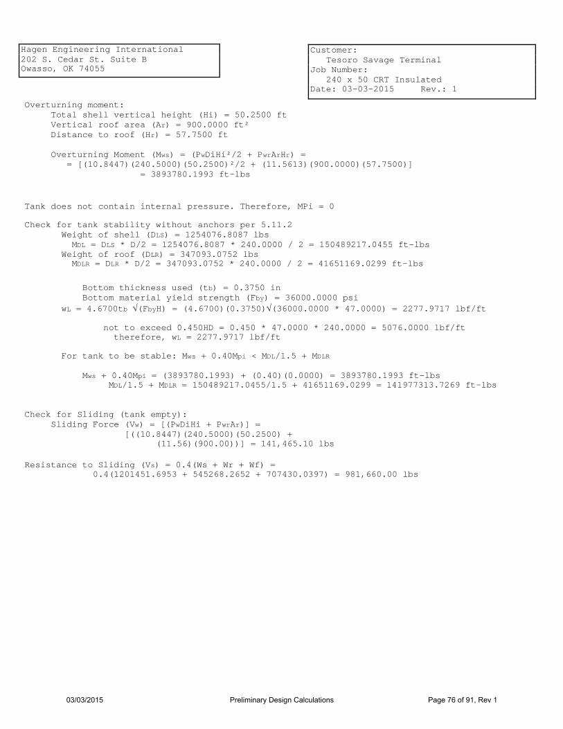
Hagen Engineering International 202 S. Cedar St. Suite B Owasso, OK 74055
Customer: Tesoro Savage Terminal Job Number: 240 x 50 CRT Insulated Date: 03-03-2015 Rev.: 1
Overturning moment: Total shell vertical height (Hi) = 50.2500 ft Vertical roof area (Ar) = 900.0000 ft² Distance to roof (Hr) = 57.7500 ft Overturning Moment (Mws) = (PwDiHi²/2 + PwrArHr) = = [(10.8447)(240.5000)(50.2500)²/2 + (11.5613)(900.0000)(57.7500)] = 3893780.1993 ft-lbs
Tank does not contain internal pressure. Therefore, MPi = 0
Check for tank stability without anchors per 5.11.2 Weight of shell (DLS) = 1254076.8087 lbs MDL = DLS * D/2 = 1254076.8087 * 240.0000 / 2 = 150489217.0455 ft-lbs Weight of roof (DLR) = 347093.0752 lbs MDLR = DLR * D/2 = 347093.0752 * 240.0000 / 2 = 41651169.0299 ft-lbs
Bottom thickness used (tb) = 0.3750 in Bottom material yield strength (Fby) = 36000.0000 psi wL = 4.6700tb √(FbyH) = (4.6700)(0.3750)√(36000.0000 * 47.0000) = 2277.9717 lbf/ft
not to exceed 0.450HD = 0.450 * 47.0000 * 240.0000 = 5076.0000 lbf/ft therefore, wL = 2277.9717 lbf/ft
For tank to be stable: Mws + 0.40Mpi < MDL/1.5 + MDLR Mws + 0.40Mpi = (3893780.1993) + (0.40)(0.0000) = 3893780.1993 ft-lbs MDL/1.5 + MDLR = 150489217.0455/1.5 + 41651169.0299 = 141977313.7269 ft-lbs
Check for Sliding (tank empty): Sliding Force (Vw) = [(PwDiHi + PwrAr)] = [((10.8447)(240.5000)(50.2500) + (11.56)(900.00))] = 141,465.10 lbs
Resistance to Sliding (Vs) = 0.4(Ws + Wr + Wf) = 0.4(1201451.6953 + 545268.2652 + 707430.0397) = 981,660.00 lbs
03/03/2015 Preliminary Design Calculations Page 76 of 91, Rev 1

Hagen Engineering International 202 S. Cedar St. Suite B Owasso, OK 74055
Customer: Tesoro Savage Terminal Job Number: 240 x 50 CRT Insulated Date: 03-03-2015 Rev.: 1
131517746.9188
907306.2601
475843.3218
347093.0752
1130973.3553
1140021.1421
0.0000
29405.3072
35355.2202
198175.1899
580623.4854
0.0000
0.0000
0.0000
343312.6708
346059.1721
105156.6711
52625.1134
7389.0259
131517746.9188
1194062.6694
707430.0397
347093.0752
1130973.3553
1140021.1421
0.0000
29405.3072
35355.2202
198175.1899
580623.4854
0.0000
0.0000
0.0000
343312.6708
346059.1721
105156.6711
52625.1134
7389.0259
Corroded (lbf) New (lbf)
Product: Total Shell Plates: Total Bottom Plates: Total Roof Plates: Total Live Load: Total Snow Load: Total Additional Dead Load: Shell Insulation: Roof Insulation: Total Rafters: Total Roof and Framing: Total Shell Appurtenances: Total Roof Appurtenances: Total Roof Appurtenances acting on Shell Live Load acting on Shell: Snow Load acting on Shell: Total of Roof acting on Shell: Total of Roof Structural acting on Shell: Total Compression Ring and Shell Stiffener
Weights
03/03/2015 Preliminary Design Calculations Page 77 of 91, Rev 1
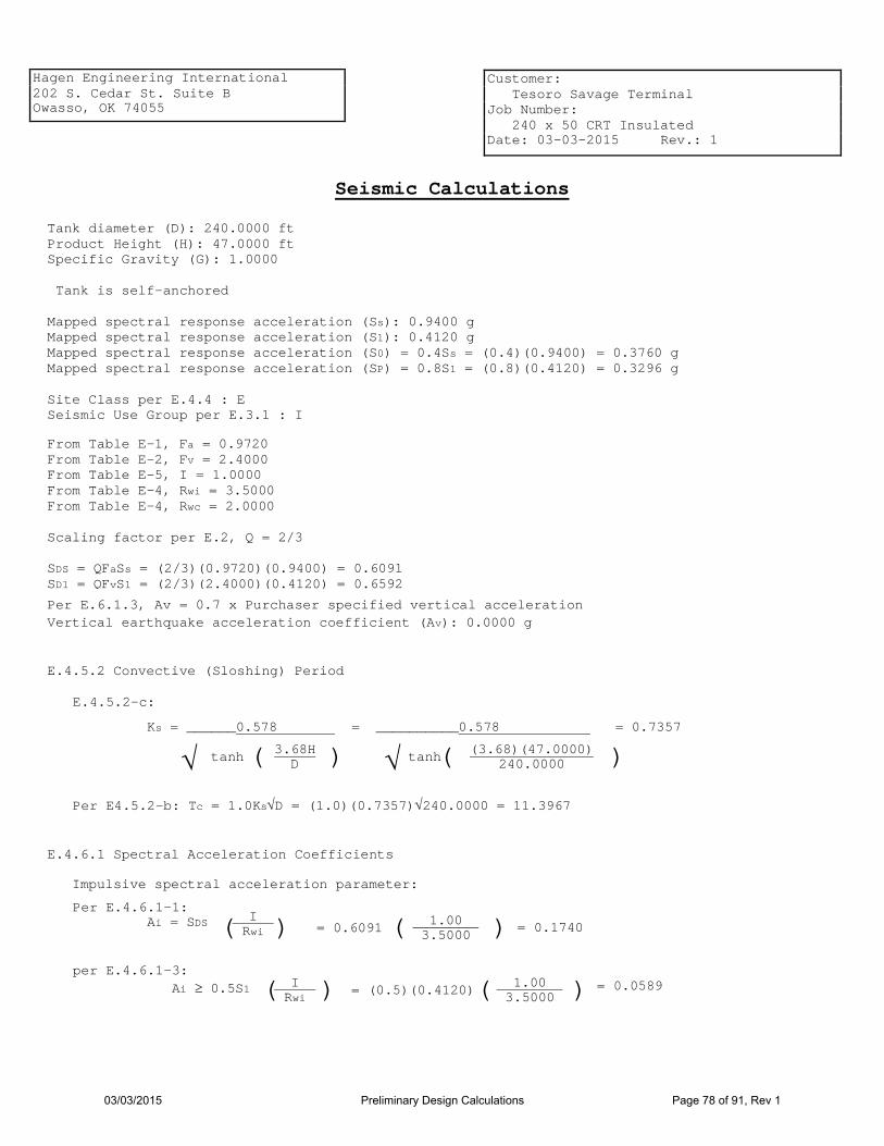
Hagen Engineering International 202 S. Cedar St. Suite B Owasso, OK 74055
Customer: Tesoro Savage Terminal Job Number: 240 x 50 CRT Insulated Date: 03-03-2015 Rev.: 1
Seismic Calculations
Tank diameter (D): 240.0000 ft Product Height (H): 47.0000 ft Specific Gravity (G): 1.0000 Tank is self-anchored Mapped spectral response acceleration (Ss): 0.9400 g Mapped spectral response acceleration (S1): 0.4120 g Mapped spectral response acceleration (S0) = 0.4Ss = (0.4)(0.9400) = 0.3760 g Mapped spectral response acceleration (SP) = 0.8S1 = (0.8)(0.4120) = 0.3296 g Site Class per E.4.4 : E Seismic Use Group per E.3.1 : I From Table E-1, Fa = 0.9720 From Table E-2, Fv = 2.4000 From Table E-5, I = 1.0000 From Table E-4, Rwi = 3.5000 From Table E-4, Rwc = 2.0000 Scaling factor per E.2, Q = 2/3 SDS = QFaSs = (2/3)(0.9720)(0.9400) = 0.6091 SD1 = QFvS1 = (2/3)(2.4000)(0.4120) = 0.6592
Per E.6.1.3, Av = 0.7 x Purchaser specified vertical acceleration Vertical earthquake acceleration coefficient (Av): 0.0000 g
E.4.5.2 Convective (Sloshing) Period
Per E4.5.2-b: Tc = 1.0Ks√D = (1.0)(0.7357)√240.0000 = 11.3967
) (3.68)(47.0000) 240.0000 ( tanh √ ) 3.68H
D ( tanh √
Ks = ______0.578 = __________0.578 = 0.7357
E.4.5.2-c:
E.4.6.1 Spectral Acceleration Coefficients Impulsive spectral acceleration parameter:
= 0.1740 ) 1.00 3.5000 ( = 0.6091
I Rwi ) (
Per E.4.6.1-1: Ai = SDS
per E.4.6.1-3: Ai ≥ 0.5S1 ( ( I
Rwi 1.00
3.5000 ) ) = (0.5)(0.4120) = 0.0589
03/03/2015 Preliminary Design Calculations Page 78 of 91, Rev 1

Hagen Engineering International 202 S. Cedar St. Suite B Owasso, OK 74055
Customer: Tesoro Savage Terminal Job Number: 240 x 50 CRT Insulated Date: 03-03-2015 Rev.: 1
However, per E.4.6.1-2, Ai ≥ 0.0070 Therefore, Ai = 0.1740
TL = 16.0000 K = 1.5
Convective spectral acceleration parameter:
= 0.0434 1.00 2.0000
1 11.3967 = (1.5)(0.6592) I
Rwc 1 Tc ) ) ) ) ( ( ( ( Ac = KSD1
Tc ≤ TL , Per E.4.6.1-4
However, Ac ≤ Ai Therefore, Ac = 0.0434
Per E.6.1.1 D/H = 240.0000/47.0000 = 5.1064 Weights: Ws = 1230857 lbs Wf = 707430 lbs Wr = Roof weight + 10% of snow = 694626 lbs WP = 131517747 lbs
(131517747) = 29732254 lbs tanh(0.866 * 5.1064) 0.866 * 5.1064 WP = tanh(0.866D/H)
0.866D/H
D/H ≥ 1.333
Per E.6.1.1-1, Wi =
Per E.6.1.1-3, Wc = 0.230D/H tanh(3.67H/D)WP = (0.230)(5.1064)[tanh(3.67/5.1064)](131517747) = 95166223 lbs
Per E.6.1-2, Vi = Ai(Ws + Wr + Wf + Wi) = (0.1740)(1230857 + 694626 + 707430 + 29732254) = 5632649 lbs Per E.6.1-3, Vc = AcWc = (0.0434)(95166223) = 4128419 lbs Per E.6.1-1, V = √(Vi² + Vc²) = √[(5632649)² + (4128419)²] = 6983593 lbs
Per E.6.1.2.1
Per E.6.1.2.1-1, Xi = 0.375H = (0.375)(47.0000) = 17.6250 ft
D/H ≥ 1.333
03/03/2015 Preliminary Design Calculations Page 79 of 91, Rev 1

Hagen Engineering International 202 S. Cedar St. Suite B Owasso, OK 74055
Customer: Tesoro Savage Terminal Job Number: 240 x 50 CRT Insulated Date: 03-03-2015 Rev.: 1
Per E.6.1.2.1-3, Xc = [
[ ] 1.0 -
cosh(3.67H/D) - 1 3.67H/D sinh(3.67H/D) H =
1.0 - cosh(3.67/5.1064) - 1
(3.67/5.1064)sinh(3.67/5.1064) ] (47.0000) = 24.4619 ft
Per E.6.1.2.2
98.0549 ft
)] - 1.0 ( (0.866 * 5.1064) tanh(0.866 * 5.1064) 1.0 + 1.333 [ 0.375
H = - 1.0 )] (0.866D/H) tanh(0.866D/H) ( 1.0 + 1.333 [ Per E.6.1.2.2-1,
Xis = 0.375
D/H ≥ 1.333
(47.0000) =
Per E.6.1.2.2-3, Xcs = [ 1.0 - cosh(3.67H/D) -1.937
3.67H/D sinh(3.67H/D) ] H =
[ 1.0 - cosh(3.67/5.1064) - 1.937 (3.67/5.1064)sinh(3.67/5.1064) ] (47.0000) = 102.7989 ft
Per E.6.1.5-1, Mrw = √[Ai(WiXi + WsXs + WrXr)]² + [Ac(WcXc)]² = √[0.1740(29732254*17.6250 + 1230857*19.9796 + 694626*52.5000)]² + [0.0434(95166223*24.4619)]² = 143412972 ft-lbs
Per E.6.1.5
Per E.6.1.5-2, Ms = √[Ai(WiXis + WsXs + WrXr)]² + [Ac(WcXcs)]² = √[0.1740(29732254*98.0549 + 1230857*19.9796 + 694626*52.5000)]² + [0.0434(95166223*102.7989)]² = 669657846 ft-lbs
Self-anchored tank (new condition)
Per E.6.2.1.1.1 Ws = 1201452 lbs wrs = 255.1621 lbf/ft ta = 0.5000 in ts = 1.0088 in Ge = G(1.0 - 0.4Av) = 1.0000(1.0 - (0.4)(0.0000)) = 1.0000 Per E.6.2.1.1.1-2, wt = Ws/(πD) + wrs = 1201452/(π ∗ 240.0000) + 255.1621 = 1848.6369 lbf/ft
03/03/2015 Preliminary Design Calculations Page 80 of 91, Rev 1

Hagen Engineering International 202 S. Cedar St. Suite B Owasso, OK 74055
Customer: Tesoro Savage Terminal Job Number: 240 x 50 CRT Insulated Date: 03-03-2015 Rev.: 1
Check annular ring: Per E.6.2.1.1.2-1b, L = 0.21600ta√(Fy/HGe) = (0.21600)(0.5000)√[36000.0000/(47.0000 * 1.0000)] = 2.9890 ft ≤ 0.035D = (0.035)(240.0000) = 8.4000 ft therefore, L = 2.9890 ft
Ls = 2.9003 ft Per E.6.2.1.1-2b, wa = 36.5HGeLs = (36.5)(47.0000)(1.0000)(2.9003) = 4975.4647 lbf/ft
= 0.365 143412972 (240.0000)²[1848.6369(1.0 - (0.4)(0.0000)) + 4975.4647 - 0.40 * 0.0000]
= Mrw D²[wt(1.0 - 0.4Av) + wa - 0.40wint]
Per E.6.2.1.1.1-1, J =
Wint = 0.0000 lbf/ft
Shell compression per E.6.2.2.1-1b where J < 0.785
σc = [wt(1 + 0.4Av) + 1.273Mrw/D²]/(12ts) = [1901.8433(1 + (0.4)(0.0000)) + (1.273)(143412972)/(240.0000)²]/(12 * 1.0088) = 418.9210 psi
Self-anchored tank (corroded condition)
Per E.6.2.1.1.1 Ws = 914695 lbs wrs = 255.1621 lbf/ft ta = 0.3750 in ts = 1.0088 in Ge = G(1.0 - 0.4Av) = 1.0000(1.0 - (0.4)(0.0000)) = 1.0000 Per E.6.2.1.1.1-2, wt = Ws/(πD) + wrs = 914695/(π ∗ 240.0000) + 255.1621 = 1468.3144 lbf/ft
Check annular ring: Per E.6.2.1.1.2-1b, L = 0.21600ta√(Fy/HGe) = (0.21600)(0.3750)√[36000.0000/(47.0000 * 1.0000)] = 2.2418 ft ≤ 0.035D = (0.035)(240.0000) = 8.4000 ft therefore, L = 2.2418 ft
Per E.6.2.1.1-1b, wa = 7.9ta√(FyHGe) = (7.9)(0.3750)√[(36000.0000)(47.0000)(1.0000)] = 3853.5282 lbf/ft ≤ 1.28HDGe = (1.28)(47.0000)(240.0000)(1.0000) = 14438.4000 lbf/ft therefore, wa = 3853.5282 lbf/ft
03/03/2015 Preliminary Design Calculations Page 81 of 91, Rev 1

Hagen Engineering International 202 S. Cedar St. Suite B Owasso, OK 74055
Customer: Tesoro Savage Terminal Job Number: 240 x 50 CRT Insulated Date: 03-03-2015 Rev.: 1
Per E.6.2.1.1.1-1, J = Mrw D²[wt(1.0 - 0.4Av) + wa - 0.40wint]
=
143412972 (240.0000)²[1468.3144(1.0 - (0.4)(0.0000)) + 3853.5282 - 0.40 * 0.0000]
= 0.468
σc = [wt(1 + 0.4Av) + 1.273Mrw/D²]/(12ts) = [1521.5208(1 + (0.4)(0.0000)) + (1.273)(143412972)/(240.0000)²]/(12 * 1.0088) = 388 psi
Shell compression per E.6.2.2.1-1b where J < 0.785
Allowable Compression Stresses in Shell per E.6.2.2.3
For new condition: GHD²/t² = (1.0000)(47.0000)(240.0000)²/(1.0088)² = 2660092
For GHD²/t² ≥ 1000000 Per E.6.2.2.3-1b, Fc = 1000000ts/D = (1000000)(1.0088)/240.0000 = 4203 psi
For corroded condition: GHD²/t² = (1.0000)(47.0000)(240.0000)²/(1.0088)² = 2660092
For GHD²/t² ≥ 1000000 Per E.6.2.2.3-1b, Fc = 1000000ts/D = (1000000)(1.0088)/240.0000 = 4203 psi
Freeboard requirements per E.7.2
Tc > 4 Per E.7.2-3, Af = KSD1I(4/Tc²) = (1.5)(0.6592)(1.0000)(4/11.3967²) = 0.0305
Freeboard equal to 0.7 times the calculated wave height is recommended but not required. The required minimum freeboard = 2.149. The available freeboard = 2.000.
Wave Height Per E.7.2-1: δs = 0.42DAf = (0.42)(240.0000)(0.0305) = 3.0695 ft Per Table E-7, minimum freeboard = 0.7δs = (0.7)(3.0695) = 2.1487 ft
Per E.6.2.1.1.3, butt welded annular plates are required.
Estimated Tank Uplift per E.7.3.1-1b tb = 0.3750 in yu = FyL²/(83300)(tb) = (36000)(2.2418)²/(83300)(0.3750) = 5.7916 in
Tank resistance to sliding per E.7.6 Per E.7.6-1, Vs = 0.4000(Ws + Wr + Wf + Wp)(1.0 - 0.4Av) = 0.4000(914695 + 659270 + 475843 + 131517747)(1.0 - 0.4 * 0.0000) = 53427022 lbs V = 6983593 lbs
03/03/2015 Preliminary Design Calculations Page 82 of 91, Rev 1

Hagen Engineering International 202 S. Cedar St. Suite B Owasso, OK 74055
Customer: Tesoro Savage Terminal Job Number: 240 x 50 CRT Insulated Date: 03-03-2015 Rev.: 1
Tank is stable against sliding.
03/03/2015 Preliminary Design Calculations Page 83 of 91, Rev 1

Hagen Engineering International 202 S. Cedar St. Suite B Owasso, OK 74055
Customer: Tesoro Savage Terminal Job Number: 240 x 50 CRT Insulated Date: 03-03-2015 Rev.: 1
Hoop Stress per E.6.1.4
G = 1.00 D = 240.0000 ft H = 47.0000 ft Ai = 0.1740 Ac = 0.0434 Av = 0.0000 D/H = 5.1064
Shell Course 01
Y = 47.0000 ft
D/H ≥ 1.333
Per E.6.1.4-1b, Ni = 4.50AiGDH [ Y H - 0.5 ( Y H ) 2
] tanh(0.866D/H) =
(4.50)(0.1740)(1.00)(240.0000)(47.0000) [ 47.0000 47.0000 - 0.5 ( 47.0000
47.0000 ) 2 ]
tanh(0.866 * 240.0000 / 47.0000) = 4415.7164 lbf/in
Per E.6.1.4-4b, Nc = 0.98AcGD²cosh[3.68(H - Y)/D] cosh[3.68H/D]
(0.98)(0.0434)(1.0000)(240.0000)²cosh[3.68(47.0000 - 47.0000)/240.0000] cosh[(3.68)(47.0000/240.0000)]
=
= 1926.4797 lbf/in
Nh = 2.60D(Y-1)G = (2.60)(240.0000)((47.0000)-1)(1.00) = 28704.0000 lbf/in
Shell thickness (t) = 1.0089 in
Per E.6.1.4-5, σT = [Nh + √Ni² + Nc²]/t = [28704.0000 + √(4415.7164)² + (1926.4797)²]/1.0089 = 33225.9519 psi
03/03/2015 Preliminary Design Calculations Page 84 of 91, Rev 1

Hagen Engineering International 202 S. Cedar St. Suite B Owasso, OK 74055
Customer: Tesoro Savage Terminal Job Number: 240 x 50 CRT Insulated Date: 03-03-2015 Rev.: 1
Allowable stress per E.6.2.4 Lesser of: 1.33SE = (1.33)(28000.0000)(1.0000) = 37240.0000 psi or 0.90FyE = (0.90)(42000.0000)(1.0000) = 37800.0000 psi Therefore, Allowable stress = 37240.0000 psi
Minimum required thickness = (σT * t)/Sa = (33225.9519 * 1.0089)/37240.0000 = 0.9002 in
03/03/2015 Preliminary Design Calculations Page 85 of 91, Rev 1
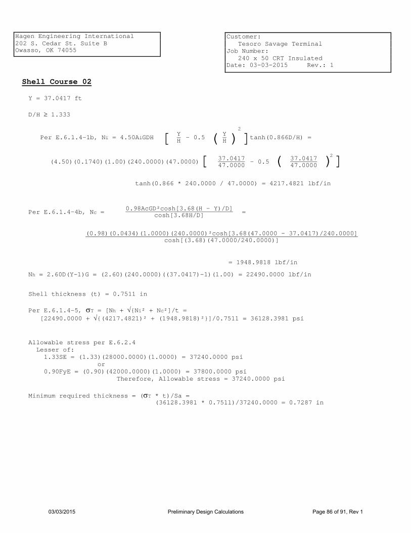
Hagen Engineering International 202 S. Cedar St. Suite B Owasso, OK 74055
Customer: Tesoro Savage Terminal Job Number: 240 x 50 CRT Insulated Date: 03-03-2015 Rev.: 1
Shell Course 02
Y = 37.0417 ft
D/H ≥ 1.333
Per E.6.1.4-1b, Ni = 4.50AiGDH [ Y H - 0.5 ( Y H ) 2
] tanh(0.866D/H) =
(4.50)(0.1740)(1.00)(240.0000)(47.0000) [ 37.0417 47.0000 - 0.5 ( 37.0417
47.0000 ) 2 ]
tanh(0.866 * 240.0000 / 47.0000) = 4217.4821 lbf/in
Per E.6.1.4-4b, Nc = 0.98AcGD²cosh[3.68(H - Y)/D] cosh[3.68H/D]
(0.98)(0.0434)(1.0000)(240.0000)²cosh[3.68(47.0000 - 37.0417)/240.0000] cosh[(3.68)(47.0000/240.0000)]
=
= 1948.9818 lbf/in
Nh = 2.60D(Y-1)G = (2.60)(240.0000)((37.0417)-1)(1.00) = 22490.0000 lbf/in
Shell thickness (t) = 0.7511 in
Per E.6.1.4-5, σT = [Nh + √Ni² + Nc²]/t = [22490.0000 + √(4217.4821)² + (1948.9818)²]/0.7511 = 36128.3981 psi
Allowable stress per E.6.2.4 Lesser of: 1.33SE = (1.33)(28000.0000)(1.0000) = 37240.0000 psi or 0.90FyE = (0.90)(42000.0000)(1.0000) = 37800.0000 psi Therefore, Allowable stress = 37240.0000 psi
Minimum required thickness = (σT * t)/Sa = (36128.3981 * 0.7511)/37240.0000 = 0.7287 in
03/03/2015 Preliminary Design Calculations Page 86 of 91, Rev 1

Hagen Engineering International 202 S. Cedar St. Suite B Owasso, OK 74055
Customer: Tesoro Savage Terminal Job Number: 240 x 50 CRT Insulated Date: 03-03-2015 Rev.: 1
Shell Course 03
Y = 27.0833 ft
D/H ≥ 1.333
Per E.6.1.4-1b, Ni = 4.50AiGDH [ Y H - 0.5 ( Y H ) 2
] tanh(0.866D/H) =
(4.50)(0.1740)(1.00)(240.0000)(47.0000) [ 27.0833 47.0000 - 0.5 ( 27.0833
47.0000 ) 2 ]
tanh(0.866 * 240.0000 / 47.0000) = 3622.7793 lbf/in
Per E.6.1.4-4b, Nc = 0.98AcGD²cosh[3.68(H - Y)/D] cosh[3.68H/D]
(0.98)(0.0434)(1.0000)(240.0000)²cosh[3.68(47.0000 - 27.0833)/240.0000] cosh[(3.68)(47.0000/240.0000)]
=
= 2017.0140 lbf/in
Nh = 2.60D(Y-1)G = (2.60)(240.0000)((27.0833)-1)(1.00) = 16276.0000 lbf/in
Shell thickness (t) = 0.5525 in
Per E.6.1.4-5, σT = [Nh + √Ni² + Nc²]/t = [16276.0000 + √(3622.7793)² + (2017.0140)²]/0.5525 = 36963.6728 psi
Allowable stress per E.6.2.4 Lesser of: 1.33SE = (1.33)(28000.0000)(1.0000) = 37240.0000 psi or 0.90FyE = (0.90)(42000.0000)(1.0000) = 37800.0000 psi Therefore, Allowable stress = 37240.0000 psi
Minimum required thickness = (σT * t)/Sa = (36963.6728 * 0.5525)/37240.0000 = 0.5484 in
03/03/2015 Preliminary Design Calculations Page 87 of 91, Rev 1

Hagen Engineering International 202 S. Cedar St. Suite B Owasso, OK 74055
Customer: Tesoro Savage Terminal Job Number: 240 x 50 CRT Insulated Date: 03-03-2015 Rev.: 1
Shell Course 04
Y = 17.1250 ft
D/H ≥ 1.333
Per E.6.1.4-1b, Ni = 4.50AiGDH [ Y H - 0.5 ( Y H ) 2
] tanh(0.866D/H) =
(4.50)(0.1740)(1.00)(240.0000)(47.0000) [ 17.1250 47.0000 - 0.5 ( 17.1250
47.0000 ) 2 ]
tanh(0.866 * 240.0000 / 47.0000) = 2631.6078 lbf/in
Per E.6.1.4-4b, Nc = 0.98AcGD²cosh[3.68(H - Y)/D] cosh[3.68H/D]
(0.98)(0.0434)(1.0000)(240.0000)²cosh[3.68(47.0000 - 17.1250)/240.0000] cosh[(3.68)(47.0000/240.0000)]
=
= 2132.1656 lbf/in
Nh = 2.60D(Y-1)G = (2.60)(240.0000)((17.1250)-1)(1.00) = 10062.0000 lbf/in
Shell thickness (t) = 0.4365 in
Per E.6.1.4-5, σT = [Nh + √Ni² + Nc²]/t = [10062.0000 + √(2631.6078)² + (2132.1656)²]/0.4365 = 30810.9021 psi
Allowable stress per E.6.2.4 Lesser of: 1.33SE = (1.33)(23200.0000)(1.0000) = 30856.0000 psi or 0.90FyE = (0.90)(36000.0000)(1.0000) = 32400.0000 psi Therefore, Allowable stress = 30856.0000 psi
Minimum required thickness = (σT * t)/Sa = (30810.9021 * 0.4365)/30856.0000 = 0.4359 in
03/03/2015 Preliminary Design Calculations Page 88 of 91, Rev 1

Hagen Engineering International 202 S. Cedar St. Suite B Owasso, OK 74055
Customer: Tesoro Savage Terminal Job Number: 240 x 50 CRT Insulated Date: 03-03-2015 Rev.: 1
Shell Course 05
Y = 7.1667 ft
D/H ≥ 1.333
Per E.6.1.4-1b, Ni = 4.50AiGDH [ Y H - 0.5 ( Y H ) 2
] tanh(0.866D/H) =
(4.50)(0.1740)(1.00)(240.0000)(47.0000) [ 7.1667 47.0000 - 0.5 ( 7.1667
47.0000 ) 2 ]
tanh(0.866 * 240.0000 / 47.0000) = 1243.9678 lbf/in
Per E.6.1.4-4b, Nc = 0.98AcGD²cosh[3.68(H - Y)/D] cosh[3.68H/D]
(0.98)(0.0434)(1.0000)(240.0000)²cosh[3.68(47.0000 - 7.1667)/240.0000] cosh[(3.68)(47.0000/240.0000)]
=
= 2297.1265 lbf/in
Nh = 2.60D(Y-1)G = (2.60)(240.0000)((7.1667)-1)(1.00) = 3848.0000 lbf/in
Shell thickness (t) = 0.2125 in
Per E.6.1.4-5, σT = [Nh + √Ni² + Nc²]/t = [3848.0000 + √(1243.9678)² + (2297.1265)²]/0.2125 = 30401.5330 psi
Allowable stress per E.6.2.4 Lesser of: 1.33SE = (1.33)(23200.0000)(1.0000) = 30856.0000 psi or 0.90FyE = (0.90)(36000.0000)(1.0000) = 32400.0000 psi Therefore, Allowable stress = 30856.0000 psi
Minimum required thickness = (σT * t)/Sa = (30401.5330 * 0.2125)/30856.0000 = 0.2094 in
03/03/2015 Preliminary Design Calculations Page 89 of 91, Rev 1


![COMPANY PROFILE...Agitated vessels Accumulators Cone roof tanks [Heat Exchangers] [Towers, Vessels and Reactors] PRODUCTS Heavy-duty band saw NC gas cutting machine Maximum weight:](https://static.fdocuments.us/doc/165x107/60f8ad02aa5a073c34565558/company-profile-agitated-vessels-accumulators-cone-roof-tanks-heat-exchangers.jpg)