
DRAFT - Network Standard - NS104 Specification for .../media/Files/Network/Documents/NS and... ·...
36
NW000-S0043 UNCONTROLLED IF PRINTED Page 1 of 36 Network Standard NETWORK Document No Amendment No Approved By Approval Date Review Date : : : : : NW000-S0043 3 Manager - Primary Systems 13/09/2016 13/09/2019 Supersedes Network Standard (NETWORK) NW000-S0043 Amendment No.2 NW000-S0043 NS104 SPECIFICATION FOR ELECTRICAL NETWORK PROJECT DESIGN PLANS
Transcript of DRAFT - Network Standard - NS104 Specification for .../media/Files/Network/Documents/NS and... ·...

NW000-S0043 UNCONTROLLED IF PRINTED Page 1 of 36
Network Standard
NETWORK
Document No Amendment No Approved By Approval Date Review Date
:::::
NW000-S0043 3 Manager - Primary Systems 13/09/2016 13/09/2019
Supersedes Network Standard (NETWORK) NW000-S0043 Amendment No.2
NW000-S0043 NS104 SPECIFICATION FOR ELECTRICAL NETWORK PROJECT DESIGN PLANS

NS104 Specification for Electrical Network Project Design Plans Amendment No. 3
NW000-S0043 UNCONTROLLED IF PRINTED Page 2 of 36
ISSUE
For issue to all Ausgrid and Accredited Service Providers’ staff associated with the design and installation of Ausgrid’s Network, and is for reference by field, technical and engineering staff.
Ausgrid maintains a copy of this and other Network Standards together with updates and amendments on www.ausgrid.com.au.
Where this standard is issued as a controlled document replacing an earlier edition, remove and destroy the superseded document
DISCLAIMER
As Ausgrid’s standards are subject to ongoing review, the information contained in this document may be amended by Ausgrid at any time. It is possible that conflict may exist between standard documents. In this event, the most recent standard shall prevail.
This document has been developed using information available from field and other sources and is suitable for most situations encountered in Ausgrid. Particular conditions, projects or localities may require special or different practices. It is the responsibility of the local manager, supervisor, assured quality contractor and the individuals involved to make sure that a safe system of work is employed and that statutory requirements are met.
Ausgrid disclaims any and all liability to any person or persons for any procedure, process or any other thing done or not done, as a result of this Standard.
All design work, and the associated supply of materials and equipment, must be undertaken in accordance with and consideration of relevant legislative and regulatory requirements, latest revision of Ausgrid’s Network Standards and specifications and Australian Standards. Designs submitted shall be declared as fit for purpose. Where the designer wishes to include a variation to a network standard or an alternative material or equipment to that currently approved the designer must obtain authorisation from the Network Standard owner before incorporating a variation to a Network Standard in a design.
External designers including those authorised as Accredited Service Providers will seek approval through the approved process as outlined in NS181 Approval of Materials and Equipment and Network Standard Variations. Seeking approval will ensure Network Standards are appropriately updated and that a consistent interpretation of the legislative framework is employed.
Notes: 1. Compliance with this Network Standard does not automatically satisfy the requirements of a Designer Safety Report. The designer must comply with the provisions of the Workplace Health and Safety Regulation 2011 (NSW - Part 6.2 Duties of designer of structure and person who commissions construction work) which requires the designer to provide a written safety report to the person who commissioned the design. This report must be provided to Ausgrid in all instances, including where the design was commissioned by or on behalf of a person who proposes to connect premises to Ausgrid’s network, and will form part of the Designer Safety Report which must also be presented to Ausgrid. Further information is provided in Network Standard (NS) 212 Integrated Support Requirements for Ausgrid Network Assets.
2. Where the procedural requirements of this document conflict with contestable project procedures, the contestable project procedures shall take precedent for the whole project or part thereof which is classified as contestable. Any external contact with Ausgrid for contestable works projects is to be made via the Ausgrid officer responsible for facilitating the contestable project. The Contestable Ausgrid officer will liaise with Ausgrid internal departments and specialists as necessary to fulfil the requirements of this standard. All other technical aspects of this document which are not procedural in nature shall apply to contestable works projects.
INTERPRETATION
In the event that any user of this Standard considers that any of its provisions is uncertain, ambiguous or otherwise in need of interpretation, the user should request Ausgrid to clarify the provision. Ausgrid’s interpretation shall then apply as though it was included in the Standard, and is final and binding. No correspondence will be entered into with any person disputing the meaning of the provision published in the Standard or the accuracy of Ausgrid’s interpretation.
KEYPOINTS
This standard has a summary of content labelled “KEYPOINTS FOR THIS STANDARD”. The inclusion or omission of items in this summary does not signify any specific importance or criticality to the items described. It is meant to simply provide the reader with a quick assessment of some of the major issues addressed by the standard. To fully appreciate the content and the requirements of the standard it must be read in its entirety.
AMENDMENTS TO THIS STANDARD
Where there are changes to this standard from the previously approved version, any previous shading is removed and the newly affected paragraphs are shaded with a grey background. Where the document changes exceed 25% of the document content, any grey background in the document is to be removed and the following words should be shown below the title block on the right hand side of the page in bold and italic, for example, Supersedes – document details (for example, “Supersedes Document Type (Category) Document No. Amendment No.”).

KEY POINTS OF THIS STANDARD
NW000-S0043 UNCONTROLLED IF PRINTED Page 3 of 36
Format of Electrical Network Project Design Plans
Electrical Network Design Plan Detail
Consultation, Negotiation and Consent Requirements
Scope and Risks Addressed
Tools and Forms None
Tools and Forms Annexure B – Compliance Checklist
This standard is Ausgrid’s specification for electrical network project design plans. It is limited to scope identified below and provides controls for associated risks as listed below:
Applies to all network project design plans for all electrical work involving Ausgrid’s distribution and Subtransmission network
Only Ausgrid may vary its intended standard or impose additional requirements other than those in this standard
Where to for more information? Section 1
This section provides formatting information for project design plans including:
Design plans must use CAD software formats (either AUTOCAD .dwg or Microstation .dgn formats)
Geo references to use Mapping Grid of Australia (MGA) co-ordinates
Ausgrid’s CAD drawing template standard symbology and layering conventions should be used
Drawing line styles and weights should be in accordance with the CAD drawing template
Drawing Scales and text sizes in accordance with the tables in Cl 5.5
Cadastral and topographic information must be included where relevant
Ausgrid will supply border templates (including the required title block) on request to external designers
Drawing sheets sizes of A3, A2 and A1 in landscape orientation
Design plan numbers to be allocated from Ausgrid’s PrjTrak system
Asset numbering will be supplied by Ausgrid prior to the design being certified or issued for construction
Must comply with NS100 for as built recording of assets
This section provides itemised lists of information to be included on project design plans as summarised below:
Construction and work schedule details to connect drawing elements with a table listing the construction schedule
Schematic or line diagrams to show existing and proposed network configuration
Project location and substation details (if applicable)
General information required Information specific to overhead
designs Information specific to underground
projects Designs should only utilise Ausgrid
approved materials and equipment unless approval requested (see NS181 Approval of Materials and Equipment and Network Standard Variations)
This section details the consultation, negotiation and consent requirements and includes:
Environmental impact assessments Consultation with relevant parties Serving notices required by legislation Obtaining consents necessary for the
project to proceed Must comply with Environmental
Planning and Assessment Act 1979 Must comply with Roads Act 1993 Must comply with Electricity Supply Act
1995 Must comply with State Environmental
Planning Policy (Infrastructure) 2007 Use Dial Before You Dig service for
other utilities information Verify availability of easement/property
rights affecting the design Comply with Work Health and Safety
legislation
Tools and Forms Annexure A – CAD Layer Naming Standard
Where to for more information? Section 5
Where to for more information? Section 6
Where to for more information? Section 7, 8
NS104 Specification for Electrical Network Project Design Plans Amendment No. 3
NW000-S0043 UNCONTROLLED IF PRINTED Page 4 of 36
Network Standard NS104
Specification for Electrical Network Project Design Plans
Contents
1.0 PURPOSE ................................................................................................................................ 6
2.0 SCOPE ..................................................................................................................................... 6
3.0 REFERENCES......................................................................................................................... 7 3.1 General .................................................................................................................................. 7 3.2 Ausgrid documents ................................................................................................................ 7 3.3 Other standards and documents ........................................................................................... 7 3.4 Acts and regulations .............................................................................................................. 8
4.0 DEFINITIONS .......................................................................................................................... 9
5.0 A FORMAT OF ELECTRICAL NETWORK PROJECT DESIGN PLANS .............................. 10 5.1 Introduction .......................................................................................................................... 10 5.2 Standard design plan conventions ...................................................................................... 10
General ....................................................................................................................... 10 5.2.1 Mapping reference points ........................................................................................... 10 5.2.2 Aerial photography ..................................................................................................... 10 5.2.3 Existing and proposed electrical infrastructure .......................................................... 10 5.2.4 Ausgrid CAD layer naming standard .......................................................................... 10 5.2.5
5.3 Standard symbols ................................................................................................................ 10 5.4 Drawing line styles and weights .......................................................................................... 11 5.5 Scales and text sizes ........................................................................................................... 11 5.6 Cadastral and topographic information ............................................................................... 12 5.7 Standard CAD drawing templates ....................................................................................... 12 5.8 Standard design plan tables and works schedule templates format ................................... 12 5.9 Title block............................................................................................................................. 12 5.10 Drawing sheet sizes .......................................................................................................... 12 5.11 Ausgrid design plan number(s) ......................................................................................... 12 5.12 Asset numbering ................................................................................................................ 13 5.13 As-built recording of network assets ................................................................................. 13
6.0 ELECTRICAL NETWORK PROJECT DESIGN PLAN DETAIL ............................................ 14 6.1 Construction and works schedule details ............................................................................ 14 6.2 Project staging detail ........................................................................................................... 14 6.3 Schematic or line diagrams (as applicable) ......................................................................... 14 6.4 Project location .................................................................................................................... 15 6.5 New substation details (if applicable) .................................................................................. 15 6.6 General information required on the design plan ................................................................ 16 6.7 Overhead design plan detail (if applicable) ......................................................................... 17 6.8 Underground design plan detail (if applicable) .................................................................... 19 6.9 Approved material and equipment and network standard variations .................................. 19
7.0 CONSULTATION, NEGOTIATION AND CONSENT REQUIREMENTS .............................. 20 7.1 General ................................................................................................................................ 20 7.2 Environmental Planning and Assessment Act 1979 ........................................................... 20 7.3 Roads Act 1993 ................................................................................................................... 21

NS104 Specification for Electrical Network Project Design Plans Amendment No. 3
NW000-S0043 UNCONTROLLED IF PRINTED Page 5 of 36
7.4 Electricity Supply Act 1995 .................................................................................................. 22 7.5 State Environmental Planning Policy (Infrastructure) 2007 ................................................. 22 7.6 Designs that affect other utility services .............................................................................. 22 7.7 Proposed easements or leases ........................................................................................... 22
8.0 WORK HEALTH AND SAFETY LEGISLATION .................................................................... 24
9.0 RECORDKEEPING ............................................................................................................... 25
10.0 AUTHORITIES AND RESPONSIBILITIES ............................................................................ 25
11.0 DOCUMENT CONTROL ........................................................................................................ 25
ANNEXURE A - CAD LAYER NAMING STANDARD ...................................................................... 26
ANNEXURE B – SAMPLE COMPLIANCE CHECKLIST ................................................................. 35

NS104 Specification for Electrical Network Project Design Plans Amendment No. 3
NW000-S0043 UNCONTROLLED IF PRINTED Page 6 of 36
1.0 PURPOSE
Network Standard NS104 is Ausgrid’s Specification for Electrical Network Project Design Plans.
The objectives of this Network Standard are:
(a) To present the required format for design plans for electrical works.
(b) To make sure that design plans meet required standards for consistency, quality and safety and provide sufficient information to enable the intended works to be cost estimated and constructed in accordance with Ausgrid’s requirements.
(c) To set out the principal requirements for obtaining Ausgrid’s approval for the works proposed in design plans.
(d) To make sure all design plans are presented in a standard, consistent and easily interpreted format which will lead to:
an excellent understanding of the intent of all aspects of the design.
a clear understanding of the scope of works to be undertaken by the person constructing the designed assets.
an accurate recording of Ausgrid’s assets which allows those assets to be correctly identified and located as required. (The integrity of Ausgrid’s GIS relies upon the accurate recording of all Ausgrid’s network assets).
(e) The various Network Standards produced by Ausgrid cover the minimum design and construction requirements for components of the network.
Only Ausgrid may:
vary its Standards (including by waiving or relaxing their requirements); or
impose requirements in addition to those contained in its Standards.
2.0 SCOPE
This Network Standard applies to all network project design plans for all electrical works involving Ausgrid’s network and:
requires that all consultation, negotiation and consent obligations listed in this Standard are satisfied, and
requires that the designer complies with all relevant provisions of the Work Health and Safety Act 2011 (NSW) and the Work Health and Safety Regulation 2011 (NSW) and prepares a Designer Safety Report in accordance with requirements of that Regulation.

NS104 Specification for Electrical Network Project Design Plans Amendment No. 3
NW000-S0043 UNCONTROLLED IF PRINTED Page 7 of 36
3.0 REFERENCES
General 3.1All work covered in this document shall conform to all relevant Legislation, Standards, Codes of Practice and Network Standards. Current Network Standards are available on Ausgrid’s Internet site at www.ausgrid.com.au.
Ausgrid documents 3.2 Bush Fire Risk Management Plan Company Form (Governance) - Network Document Endorsement and Approval Company Procedure (Governance) - Network Document Endorsement and Approval Company Procedure (Network) - Production / Review of Engineering Technical Documents
within BMS Customer Installation Safety Plan Division Workplace Instruction (Network) – Production /review of Network Standards ES4 Service Provider Authorisation Electrical Safety Rules Electricity Network Safety Management System Manual NS100 Field Recording of Network Assets NS109 Design Standards for Overhead Supply Developments and Distribution Centres NS110 Design and Construction Standards for URDs NS112 Design Standards for Industrial and Commercial Developments NS113 Site Selection and Construction Design Requirements for Chambers Substations NS114 Electrical Design and Construction Standards for Chamber Type Substations NS116 Design Standards for Distribution Equipment Earthing NS117 Design and Construction Standards for Kiosk Type Substations NS119 Street Lighting Design and Construction NS122 Pole Mounted Substation Construction NS125 Specification for Low Voltage Overhead Conductors NS126 Construction of High Voltage Overhead Mains NS130 Specification for Laying Underground Cables up to and including 11kV NS135 Specification for the Construction of Overhead Sub-transmission Lines NS141 Site Selection and Site Preparation Standards for Kiosk Type Substations NS143 Easements, Leases and Rights of Way NS148 Overhead Line Support, Street Light Column, Pit and Pillar Numbering NS149 Drawing Content for Chamber Type Substations, Control Points, Cable Risers and
Ductlines NS168 Specification for the Design and Construction of 33kV, 66kV and 132kV Underground
Cables NS172 Design Requirements for Cable Jointing Pits and Vaults NS174 Environmental Procedures NS174A SER NS174B SER Guidance Notes NS174C Environmental Handbook for Construction and Maintenance NS181 Approval of Materials and Equipment and Network Standard Variations NS212 Integrated Support Requirements for Ausgrid Network Assets NS220 Overhead Design Manual NS261 Requirement for Design Compliance Framework for Network Standards Public Electrical Safety Awareness Plan Public Lighting Management Plan Tree Safety Management Plan
Other standards and documents 3.3 AS 1100 Technical Drawing – General Principles AS/NZS 7000 Overhead line design ENA Doc 001-2008 National Electricity Network Safety Code

NS104 Specification for Electrical Network Project Design Plans Amendment No. 3
NW000-S0043 UNCONTROLLED IF PRINTED Page 8 of 36
Acts and regulations 3.4 Electricity Supply (General) Regulation 2014 (NSW)
Electricity Supply (Safety and Network Management) Regulation 2014
Electricity Supply Act 1995
Environmental Planning and Assessment Act 1979 (EP&A Act)
Roads Act 1993
State Environmental Planning Policy (Infrastructure) 2007
Work Health and Safety Act 2011 and Regulation 2011

NS104 Specification for Electrical Network Project Design Plans Amendment No. 3
NW000-S0043 UNCONTROLLED IF PRINTED Page 9 of 36
4.0 DEFINITIONS
Accreditation Scheme
The scheme established in accordance with Part 9 of the Electricity Supply (Safety and Network Management) Regulation 2014 (NSW) and administered by NSW Trade and Investment.
Accredited Service Provider (ASP)
An individual or entity accredited by the NSW Department of Industry, Division of Resources and Energy, in accordance with the Electricity Supply (Safety and Network Management) Regulation 2014 (NSW).
ASP/3 A person or company who holds current ASP/3 authorisation, as defined in Ausgrid’s ES4 Service Provider Authorisation and accreditation in accordance with the Accreditation Scheme to design electricity reticulation systems.
Business Management System (BMS)
An Ausgrid internal integrated policy and procedure framework that contains the approved version of documents.
DBYD Dial Before You Dig
Design Certification
Is defined in Ausgrid’s Design Contract – Connection Assets and means Ausgrid’s consent, subject to limitations stipulated in Clause 10 of that contract, to the use of a design plan for the construction of electricity assets that Ausgrid will own when they are electrified.
Designer An Ausgrid employee, contractor to Ausgrid or ASP/3 who is duly qualified to produce design plans
Design plan An Electrical Network Project Design Plan
Document control Ausgrid employees who work with printed copies of document must check the BMS regularly to monitor version control. Documents are considered “UNCONTROLLED IF PRINTED”, as indicated in the footer.
Electrical Network Project Design Plan
A CAD drawing in electronic format that details proposed alterations to Ausgrid’s Network.
GIS Ausgrid’s Geographic Information System
Network Standard A document, including Network Planning Standards, that describes the Company's minimum requirements for planning, design, construction, maintenance, technical specification, environmental, property and metering activities on the distribution and transmission network. These documents are stored in the Network Category of the BMS repository.
PrjTrak Ausgrid’s design plan registration system for GIS data capture.
REF Review of Environment Factors
Review date The review date displayed in the header of the document is the future date for review of a document. The default period is three years from the date of approval. However a review may be mandated at any time where a need is identified due to changes in legislation, organisational changes, restructures, occurrence of an incident or changes in technology or work practice.
RMS Roads & Maritime Services
SAP Ausgrid’s project and asset management system
Standard Design Plan Conventions
Refers to all standard drawing templates, border formats, design plan tables and work schedule templates as detailed in Ausgrid's internal and external Standard CAD Drawing Templates. Ausgrid will provide the standard CAD drawing template to external designers upon request.

NS104 Specification for Electrical Network Project Design Plans Amendment No. 3
NW000-S0043 UNCONTROLLED IF PRINTED Page 10 of 36
SER Summary Environmental Report
TDMS Ausgrid’s Technical Documents Management System.
5.0 A FORMAT OF ELECTRICAL NETWORK PROJECT DESIGN PLANS
Introduction 5.1The intent of the design plan is to provide a safe and unambiguous method for Ausgrid employees to record changes in and update Ausgrid’s asset management systems and for construction employees to construct, upgrade or make changes to Ausgrid’s network.
All design plans must be capable of being clearly and completely copied or printed in black and white.
Standard design plan conventions 5.2This section outlines the conventions that must be used for the production of electrical designs for network projects in standard CAD digital file format.
General 5.2.1Design plans must be based on current CAD software. Files supplied to Ausgrid by ASP/3 designers must be .dwg format. Design plans should conform to Ausgrid’s standard symbology and layering conventions, which are shown in Ausgrid’s standard CAD drawing template, and should detail all existing and proposed electrical network infrastructure, together with any relevant cadastral information.
Mapping reference points 5.2.2All design plans should be geo-referenced to Geocentric Datum of Australia GDA94, Mapping Grid of Australia MGA56 coordinates, units in metres.
Aerial photography 5.2.3Raster images or aerial photography incorporated in the design plan should be placed on the Ausgrid Layer XT_(image or picture name) as detailed in Table A1 – Layer Name Component – USE.
Existing and proposed electrical infrastructure 5.2.4CAD or DXF files of existing electrical infrastructure must be sourced from the GIS. These files conform to Ausgrid’s standard layering specification and are geo-referenced in MGA coordinates.
Existing GIS information should be checked for accuracy with respect to what is actually constructed on-site. The correction of any inaccuracies is to be incorporated into the CAD design.
Proposed electrical network alterations must be based upon this existing information and use the same Ausgrid standard layering naming conventions and MGA coordinate references.
Ausgrid CAD layer naming standard 5.2.5Standard layer names for existing and proposed electrical works are included in Ausgrid’s CAD template provided and are detailed in Annexure A - CAD Layer Naming Standards.
The CAD layer standard is made up of various components: describing the existing and proposed electrical infrastructure (eg LV_OH_EXIST, HV_SUB_PROP etc)
Standard symbols 5.3Ausgrid’s standard symbols for existing and proposed assets must be used for common infrastructure in all design plans.
Standard Symbols and their correct layer allocation are shown in Ausgrid’s standard CAD drawing template.

NS104 Specification for Electrical Network Project Design Plans Amendment No. 3
NW000-S0043 UNCONTROLLED IF PRINTED Page 11 of 36
Wherever practicable, symbols should be shown in the correct location with respect to other infrastructure items eg overhead switch (LV links or HV ABSs) symbols should be shown on the correct side of the pole on which the switch is to be installed. Where necessary this and the associated connections should be detailed in a suitable note or sketch on the design plan to remove any confusion. It should be noted that in GIS symbols are shown cartographically (schematically) and therefore do not necessarily reflect the physical relationship between items eg in GIS overhead switches may be shown on the side of a pole opposite to which it is actually installed.
Drawing line styles and weights 5.4Standard line styles and line weights are set up on the associated layers in Ausgrid’s standard CAD drawing template.
Ausgrid’s standard line styles and weights are to be used on all design plans.
Scales and text sizes 5.5The design plan is to be legibly drawn at true scale (1 drawing unit = 1 metre). All symbols and annotations must be scaled so as to be legible in the design plans.
Scales must be standard metric scales to AS 1100.101. The preferred scale for most work is 1:500; however, 1:250 may be required for underground plans in high density areas. As a guide, refer to the table below for applicable scale usage.
Table 1 – Standard Drawing Scales
Construction Plan Views
1:250 High Density Plans
1:500 Urban Plans
1:1000 Semi-Rural Plans
1:2000 Rural Overhead Plans Only
1:4000 Rural Overhead Plans Only
Detailed Plan Views
1:10 Congested high density areas
1:20 High density areas
1:50 Chamber Substation layouts
1:100 Kiosk layout
1:200 General focus area
1:250 General focus area
The minimum text size is 2.5 mm, i.e. equivalent to font size 12 lower case type.
Refer to table below for applicable text sizes.
Table 2 – Standard Text Sizes
Name Font Size CAD Style
Data 2.5mm Arial
Header 3.5mm Arial
Title 5.0mm Arial
Each design plan sheet shall have a scale bar drawn to indicate the scale of the plan, so that any scale variations after electronic transmission or photocopying will be detectable.

NS104 Specification for Electrical Network Project Design Plans Amendment No. 3
NW000-S0043 UNCONTROLLED IF PRINTED Page 12 of 36
All separate plan sections shown on the design plan shall indicate the scale of the section and have a scale bar shown for that section.
Cadastral and topographic information 5.6All design plans must include all proposed cadastral changes and topographic information associated with new or altered developments requiring electricity supply.
Cadastral and Topographic information required on design plans includes where relevant:
Existing / Proposed road boundaries and names.
Existing / Proposed lot boundaries.
Existing / Proposed lot dimensions.
Existing / Proposed Lease or Easements.
Road centrelines.
Existing / Proposed lot and house numbers.
Surrounding prominent cadastral features (parks, rivers etc.).
Contours – major / minor.
100 year flood area.
Kerb and gutter definition.
Driveways.
Standard CAD drawing templates 5.7Ausgrid standard CAD drawing templates and border formats are to be used for all design plans. These templates provide a consistent format for use by the designer, construction employees and in Ausgrid’s Asset Management Systems.
Ausgrid will provide Authorised ASP/3 designers with access to the latest version of the standard external CAD design template.
Note: It is the responsibility of designers to make sure they use the latest CAD template versions.
Standard design plan tables and works schedule templates format 5.8The standard format for design plan tables and works schedule templates is to be used when presenting design data on all design plans. This format provides a consistent and structured layout that clearly describes the information relevant to the project. ASPs must use the tables and templates contained in Ausgrid’s NET CAD external design template obtainable from Ausgrid’s website: www.ausgrid.com.au. Ausgrid employees may use tables and templates as approved for their particular work group.
The design tables and works schedules are to be grouped together on either the left or right side of the design plan. (They must not simply consist of words or references scattered across the plan.) Where possible they should appear on the same sheet as the referenced drawing. If this is not possible then they should be grouped onto a separate sheet and given the next sheet number.
Title block 5.9The title block is incorporated into the standard drawing border template. All data fields in the standard title block should be completed as applicable.
Drawing sheet sizes 5.10Design plan drawings should be drawn on A3, A2 or A1 sheets in landscape orientation.
Ausgrid design plan number(s) 5.11All design plans are to be identified with a unique number allocated from Ausgrid’s PrjTrak system which must be included in the title block of the design plan. One PrjTrak number may appear on multiple different drawings associated with a particular project. This PrjTrak number identifies the project and both Ausgrid’s region and the classification of the work.

NS104 Specification for Electrical Network Project Design Plans Amendment No. 3
NW000-S0043 UNCONTROLLED IF PRINTED Page 13 of 36
Allocation of the PrjTrak number makes sure work which modifies or changes any component of Ausgrid’s network will be recorded in the GIS. The PrjTrak number must also be indicated on all electrical network installation and alteration work records.
The SAP project number provides a reference to the controlling Ausgrid project for the design plan.
Projects involving the design or alteration of a chamber substation or sub-transmission lines must also include a drawing number allocated from the TDMS. Ausgrid will attach a copy of the approved drawings to the TDMS.
Asset numbering 5.12Each proposed asset must be correctly labelled in the design plan and the correct asset symbol must be allocated to each such asset.
Ausgrid will allocate asset numbers for poles, pillars, HV and LV links, air break switches, substations etc. prior to the design plan being certified or issued for construction.
As-built recording of network assets 5.13The objective of as-built recording is to provide an accurate record of the position, type and quantity of Ausgrid’s assets after construction for entry into the GIS.
The GIS and related asset management databases rely upon the timely and accurate identification and location of both overhead and underground network constructions.This information is used to provide asset locations to the public through Dial Before You Dig.
Ausgrid’s employees, contractors and Accredited Service Providers must comply with the requirements of Network Standard NS100 - Field Recording of Network Assets, for as-built recording of network assets.
NS104 Specification for Electrical Network Project Design Plans Amendment No. 3
NW000-S0043 UNCONTROLLED IF PRINTED Page 14 of 36
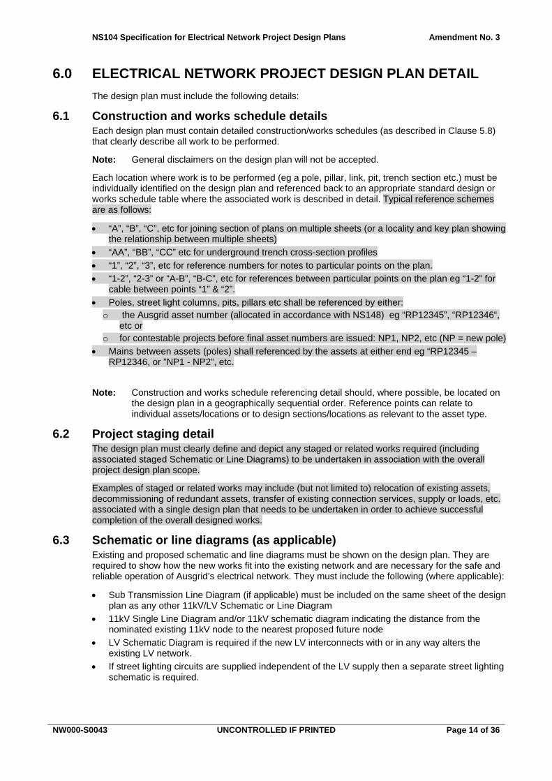
6.0 ELECTRICAL NETWORK PROJECT DESIGN PLAN DETAIL
The design plan must include the following details:
Construction and works schedule details 6.1Each design plan must contain detailed construction/works schedules (as described in Clause 5.8) that clearly describe all work to be performed.
Note: General disclaimers on the design plan will not be accepted.
Each location where work is to be performed (eg a pole, pillar, link, pit, trench section etc.) must be individually identified on the design plan and referenced back to an appropriate standard design or works schedule table where the associated work is described in detail. Typical reference schemes are as follows:
“A”, “B”, “C”, etc for joining section of plans on multiple sheets (or a locality and key plan showing the relationship between multiple sheets)
“AA”, “BB”, “CC” etc for underground trench cross-section profiles
“1”, “2”, “3”, etc for reference numbers for notes to particular points on the plan.
“1-2”, “2-3” or “A-B”, “B-C”, etc for references between particular points on the plan eg “1-2” for cable between points “1” & “2”.
Poles, street light columns, pits, pillars etc shall be referenced by either: o the Ausgrid asset number (allocated in accordance with NS148) eg “RP12345”, “RP12346“,
etc or o for contestable projects before final asset numbers are issued: NP1, NP2, etc (NP = new pole)
Mains between assets (poles) shall referenced by the assets at either end eg “RP12345 – RP12346, or ”NP1 - NP2”, etc.
Note: Construction and works schedule referencing detail should, where possible, be located on the design plan in a geographically sequential order. Reference points can relate to individual assets/locations or to design sections/locations as relevant to the asset type.
Project staging detail 6.2The design plan must clearly define and depict any staged or related works required (including associated staged Schematic or Line Diagrams) to be undertaken in association with the overall project design plan scope.
Examples of staged or related works may include (but not limited to) relocation of existing assets, decommissioning of redundant assets, transfer of existing connection services, supply or loads, etc. associated with a single design plan that needs to be undertaken in order to achieve successful completion of the overall designed works.
Schematic or line diagrams (as applicable) 6.3Existing and proposed schematic and line diagrams must be shown on the design plan. They are required to show how the new works fit into the existing network and are necessary for the safe and reliable operation of Ausgrid’s electrical network. They must include the following (where applicable):
Sub Transmission Line Diagram (if applicable) must be included on the same sheet of the design plan as any other 11kV/LV Schematic or Line Diagram
11kV Single Line Diagram and/or 11kV schematic diagram indicating the distance from the nominated existing 11kV node to the nearest proposed future node
LV Schematic Diagram is required if the new LV interconnects with or in any way alters the existing LV network.
If street lighting circuits are supplied independent of the LV supply then a separate street lighting schematic is required.

NS104 Specification for Electrical Network Project Design Plans Amendment No. 3
NW000-S0043 UNCONTROLLED IF PRINTED Page 15 of 36
Note 1: All schematic or line diagrams must reflect Ausgrid’s standard System Diagram symbols (referred to in Clause 5.3 above) and should indicate the nearest isolation point on either side of the proposed work including all control points, relevant system switch and asset numbers.
Note 2: A schematic or line diagram is required (eg PT replacement or rectification of low mains) to show the location of the work regardless of whether or not there is any change between the existing and final arrangement.
Note 3: If staged or related works are to be undertaken in association with the overall project design plan scope, then the appropriate HV, LV or SL schematic or line diagram reflecting those staged works (if applicable) must also be depicted on the design plan.
Project location 6.4A locality sketch is to be included on all plans so that the project location is clearly shown on the drawing. Existing street and cross street details, street/RMB/lot and DP numbers must be shown in order to precisely locate the area in which the work is required.
New substation details (if applicable) 6.5 Sub Name.
Sub number.
Address.
Sub type – eg ‘KK’, ‘KL’, ‘KJ’, ‘SI’, ‘P1’, ‘P3’ etc.
Size (kVA).
Vector Group.
Tap setting.
HV switchgear eg HDO, RMIFS, RMICB, FS, etc including make and model.
HV fuse details.
Load cycle - if the load cycle is indeterminable prior to commissioning, a default load cycle should be assigned as the following: (i) load cycle A - for chamber, kiosks, outdoors enclosures and surface structure substations.
(ii) load cycle D - for Pole Transformers.
Phasing detail (if applicable).
LV board detail, eg 800/400/400Amp.
LV distributor names and numbers.
Transformer LV link rating.
LV control type and size – eg LV CB, fuse.
Earthing requirements (electrode and cable detail, combined or segregated).
Location of the Earth Fault Indicator(s) (EFI) is to be shown on the proposed system diagram and substation schematic drawings.
Substation piering detail (to appropriate standard drawing and any site specific requirements).
Substation detail plan showing details of surrounding environment and structures at 3m, 6m and 10m distances (when relevant to the design).
Master options list and MDI CT ratio (for pole substations).
Easement plan detail (sketch on design plan, detailed survey drawing as separate sheet).
Note: The above detail is typical for all substation types. Chamber Substations will require additional relevant details and information in accordance with Ausgrid’s Network Standards NS113 Site Selection and Construction Design Requirements for Chambers Substations, NS114 Electrical Design and Construction Standards for Chamber Type Substations and NS149 Drawing Content for Chamber Type Substations, Control Points, Cable Risers and Ductlines.

NS104 Specification for Electrical Network Project Design Plans Amendment No. 3
NW000-S0043 UNCONTROLLED IF PRINTED Page 16 of 36
General information required on the design plan 6.6Description of all work to be performed (to be detailed in Ausgrid’s standard design tables/schedule template format). ASPs must use the tables and schedules contained in Ausgrid’s NET CAD external design template obtainable from Ausgrid’s website: www.ausgrid.com.au. Ausgrid employees may use tables and schedules as approved for their particular work group.
Include the following note and make it clearly visible:
CHECK FOR OTHER SERVICES BEFORE BORING OR EXCAVATING – phone Dial-Before-You-Dig on TELEPHONE 1100 OR AT WWW.1100.COM.AU.
Include the following notes and make them clearly visible:
THIS DESIGN PLAN CANNOT BE USED FOR CONSTRUCTION PURPOSES UNTIL THE LOCATION OF ALL EXISTING SERVICES IS VERIFIED.
THE INFORMATION PROVIDED IN THIS DESIGN PLAN MUST BE CHECKED ON SITE AND THE MOST CURRENT INFORMATION ON THE CONFIGURATION OF ALL SERVICES (INCLUDING AUSGRID'S NETWORK) MUST BE VERIFIED IMMEDIATELY BEFORE CONSTRUCTION COMMENCES BY CONTACTING DIAL-BEFORE-YOU-DIG BY TELEPHONE ON 1100 OR AT WWW.1100.COM.AU.
DIAL-BEFORE-YOU-DIG INFORMATION MUST NOT BE OLDER THAN 20 BUSINESS DAYS AT THE TIME OF CONSTRUCTION.
If the land base supplied by Ausgrid with the existing electrical infrastructure (see 5.2.4) is retained in the design, include the following note and make it clearly visible:
THIS INFORMATION INCLUDES DATA FROM THE NSW DIGITAL CADASTRAL DATABASE BY LAND AND PROPERTY INFORMATION © 2016, USED UNDER CREATIVE COMMONS LICENCE VERSION 4.0.
Any design specific detail relevant to an Embedded Generation connection is to be provided as supporting documentation to the design plan, with reference to the specific generator design document(s). These must be clearly stated on the design plan.
A notation must be included to indicate where other services are located near a worksite and may impact on the construction of assets included in the design plan - for instance, telecommunications, gas, water, stormwater, sewerage or other assets.
An appropriate earthing design is required for all sub transmission and distribution equipment that needs to be earthed An earthing design report is to be provided as supporting documentation to the design plan and the design plan must include a clear reference to the earthing design report. In addition, an earthing construction electrode and cable detail plan is required for each piece of equipment that requires an earthing design. This plan is to be included on the design plan.
Note: To manage the design of earthing systems for distribution equipment, Ausgrid has developed a design tool and database called ‘NEOn’ (Network Earthing Online). This is detailed in Ausgrid’s Network Standard NS116 – Design Standards for Distribution Equipment Earthing.
The following must be included:
North point.
Legend (must accurately reflect all symbols used).
Clearly labelled property lines.
Lot and DP numbers as appropriate.
Street names, house numbers or Road Side Mail Box (RMB) numbers.
Relevant details of proposed land use and title (eg number of dwellings, school, type of commercial, community or strata title etc).
Any access problems, constraints or other matters affecting access.

NS104 Specification for Electrical Network Project Design Plans Amendment No. 3
NW000-S0043 UNCONTROLLED IF PRINTED Page 17 of 36
Details of any known asbestos cement conduits or troughing should be marked on the design drawings.
Any known structures, objects or other obstructions.
Any relevant special features such as rock, sandy or flood prone areas.
Design plan assets must be geo-referenced correctly (eg to an existing Ausgrid pole, pillar or survey peg etc).
All proposed and existing assets must be accurately dimensioned and referenced to known cadastral points (eg lot, easement, road boundaries).
Relevant feeder number(s), feeder zone and page reference must be shown.
LV distributor/feeder number/name must be included (if applicable).
Existing and proposed asset numbers – pole, pillar, ABS, control point, etc.
Location and dimensions of existing and proposed easements to be shown where applicable.
If it is proposed to extinguish any easements, these must be clearly marked.
Street lighting details – category, location, size, type, mounting height, bracket type, etc.
Details of any agreement to pay street lighting alteration/annual charges by Local Council/RMS/RailCorp (if applicable) must be provided as supporting documentation to design plan.
Existing and proposed assets and assets that will be removed (eg poles, pillars, substations, links, ground and pole stays, street lights, overhead and underground circuits, etc) must be shown, with associated asset reference numbers, where applicable.
Existing distribution centre(s) details: (i) Location
(ii) Number
(iii) Name
HV and LV side identification of kiosk type substations.
Protection details.
LV voltage drop calculations (if applicable).
Special environmental control requirements (if applicable).
Notation on the design plan referencing any existing/proposed Pioneer schemes.
Tree clearing requirements.
Other relevant details pertaining to the project.
Any additional information requested by Ausgrid.
Overhead design plan detail (if applicable) 6.7The application name and version number of overhead line design software used in the design plan must be included.
Profiles of overhead designs must be drawn to scale and must include suitable vertical and horizontal scales.
Ground and conductor profiles including poles, conductors and ground clearances (as appropriate for the voltage) at maximum operating temperature (as nominated by Ausgrid) must be included. Profile drawings for designs prepared by Ausgrid may not be required on the design plan depending on internal design process requirements.
Typical maximum operating temperatures are shown in Ausgrid’s Network Standards NS109 Design Standards for Overhead Developments and Distribution Centre and NS135 Specification for the Construction of Overhead Subtransmission Lines.
For individual projects, the maximum operating temperature will be nominated by Ausgrid.
Pole loadings and details of ground strengths used in calculations are to be provided as supporting documentation to the design plan. Examples of pole loadings and ground strength calculations are provided in Ausgrid’s Network Standard NS220 Overhead Design Manual.

NS104 Specification for Electrical Network Project Design Plans Amendment No. 3
NW000-S0043 UNCONTROLLED IF PRINTED Page 18 of 36
The design plan must include the following where relevant:
Overhead design software inputs and outputs as supporting documentation demonstration design compliance.
Span lengths.
Conductor design and ruling spans.
Type of pole – wood, steel, pillar standard, concrete, base plate mounted etc.
Size/strength of each pole.
Footing diameter and sinking depth of each pole.
Concrete footing details for poles where required i.e., concrete type (bagged and tamped, poured etc), strength (MPa) plus tamping intervals.
A structural engineering report must be provided where pole footing strength may be impacted by civil works such as retaining wall, embankment/batter, piers, trenching works, etc. The report is to be provided as supporting documentation to the design plan; and the design plan must include a clear reference to the structural engineering report. The report must certify that the pole foundation is capable of supporting the pole when subjected to loads in accordance with Ausgrid’s Network Standard NS220 Overhead Design Manual and Australian Standard AS/NZS 7000 – Overhead Line Design.
Specific foundation design details in accordance with NS220. Soil types in some areas are available in GIS/Scout.
Existing and proposed finished surface levels.
Type, size and strength of stay wires and fittings.
The construction type/arrangement of each pole from Ausgrid Network Standards. Sketches showing any non-standard cross-arm/stay positions must be shown and approved in accordance with NS181.
Conductor/cable types and sizes.
Conductor design temperatures.
If non-standard construction, conductor attachment heights and circuit separation at each pole must be shown and approved in accordance with NS181.
Mid span clearances between circuits at worse case conditions for each span. These may be shown on the plan or included in supporting documentation. The worst case conditions are defined in the relevant Network Standards.
Line deviation angle for each pole if required for construction.
Coordinates for each new pole
Conductor tensions.
Conductor stringing tables.
Full detail of vibration damping design (if applicable).
LV service(s) augmentation or relocation detail.
Side of pole from which the transformer is to be hung, for pole transformer type distribution centres (PTs) (although may need to be revised during construction to account for phasing).
Side of pole from which crossarms or other equipment is to be installed, where a particular orientation is necessary to facilitate construction eg installation of UGOHs.
Proposed bonds and terminations, and connection arrangements for aerial conductors and at underground overhead connections UGOHs.
Location of surge arresters and earth point covers (CCT construction).
Location of air break switches (ABS), HV and LV links UGOHs, surge arresters (SAs), current limiting arcing horns (CLAHs) etc, including the orientation relative to other infrastructure (eg side of pole on which to be constructed).

NS104 Specification for Electrical Network Project Design Plans Amendment No. 3
NW000-S0043 UNCONTROLLED IF PRINTED Page 19 of 36
Underground design plan detail (if applicable) 6.8 The application name and version number of U/G design (cable pulling tension) software used in
the design plan must be included.
Trench/underbore/cable/conduit/pit detail(s) at each change of the configuration along any cable route.
Calculated maximum cable pulling tension in kN (from cable pulling tension program).
Recommended direction of cable pull
Designed minimum internal cable bending radii for each cable section pull during and after installation.
Cross sections of cable trench, road crossing, underbore and ductline.
Proposed cable joints including types of joints, eg LV 2-39, HV 2-27, 3:1, 1:1 etc and connection arrangements. Non-standard joint kits will require separate Ausgrid approval (manufacturer part codes to be noted on the design plan).
Soil type (sand with sandstone, sandy clay, heavy clay etc) (if available). Soil types in some areas are available in GIS/Scout.
Installation materials eg backfill material etc.
A certified structural engineering report must be provided where required .eg design details of bollards, kerbs, site specific asset protection, walls etc. The report is to be provided as supporting documentation to the design plan with reference to the report stated clearly on the design plan.
Cover requirements for underground cables, including details of surface cover type of any areas to be excavated including full details of any surface restoration that will be required.
Existing and proposed finished surface levels.
Elevation(s) showing the ground slope(s) adjoining a kiosk site, together with details of retaining walls and/or batter where required.
Note: Retaining walls and batter must be constructed of non-perishable material such as concrete or brick.
Where shared trenching is proposed with Telstra, Optus or AGL, the arrangements and installations must be in accordance with the applicable trench sharing agreement.
Approved material and equipment and network standard variations 6.9The designer must include only Ausgrid approved standard designs, layouts, materials and equipment in the design.
In addition to already approved materials and equipment, Accredited Service Providers (ASPs), manufacturers and suppliers may request Ausgrid to consider approval of other materials and equipment. Where the designer wishes to include a variation to a network standard or an alternative material or equipment to that currently approved the process as outlined in NS181 Approval of Materials and Equipment and Network Standard Variations must be used. A copy of any successful NS181 approval(s) relating to the Design Plan must be submitted with the design for certification.

NS104 Specification for Electrical Network Project Design Plans Amendment No. 3
NW000-S0043 UNCONTROLLED IF PRINTED Page 20 of 36
7.0 CONSULTATION, NEGOTIATION AND CONSENT REQUIREMENTS
General 7.1The designer is required to meet a number of legislated requirements to consult with various public or government authorities and/or serve notices on such bodies regarding impending works on Ausgrid’s network assets.
The designer is responsible for (among other things):
complying with Ausgrid’s requirements for environmental impact assessment;
consulting with relevant parties;
serving any notices required by legislation;
obtaining any consents necessary for proposed works to proceed;
if necessary, adjusting the design to take into account environmental considerations, submissions received or conditions imposed as a result of the consultations and notices referred to above; and
liasing with Ausgrid’s Property group to determine the most commercially appropriate location for new assets that are to be located on Ausgrid property.
Note: Where the designer has consulted with or notified relevant parties as required in this section, all responses must be provided, including a statement of nil response if applicable.
Parties that are to be consulted include those:
who are entitled by legislation to make submissions (eg section 45 of the Electricity Supply Act 1995 or, in relation to a proposed substation, the Infrastructure SEPP);
whose consent is required before the designed assets can be constructed (eg RMS in relation to assets proposed to be located in, on or under a classified road);
who may be able to provide information which may affect the design (eg Dial Before You Dig and utility providers);
who may be affected by the proposed works (eg a neighbour over whose land an easement for proposed works will be required, or whose views may be impacted); or
who may be needed to provide information to assist with the design (eg a surveyor engaged to advise of possible existing encumbrances on a development property).
Ready access to NSW legislation, including Environmental Planning instruments, is available via the internet. One source is http://www.legislation.nsw.gov.au/.
Environmental Planning and Assessment Act 1979 7.2The Environmental Planning and Assessment Act 1979 (EP&A Act) and instruments under that Act are the primary sources of Ausgrid’s obligations with respect to planning and development. Most activities conducted on Ausgrid’s network are carried out under Part 5 of the EP&A Act, where Ausgrid is the determining authority.
Conditions of consent imposed on a private developer by local councils under Part 4 of the EP&A Act must also be taken into account when a design plan is drawn up.
Where Ausgrid is the determining authority for a proposed activity, the initial SER or REF undertaken under Part 5 of the EP&A Act must be completed in accordance with Ausgrid’s NS174 Environmental Procedures. In the case of an SER, this includes:
NS174A SER
NS174B SER Guidance Notes
NS174C Environmental Handbook for Construction and Maintenance

NS104 Specification for Electrical Network Project Design Plans Amendment No. 3
NW000-S0043 UNCONTROLLED IF PRINTED Page 21 of 36
The person preparing the SER must have current certification in Ausgrid's SER training.
All SERs must be verified by Ausgrid and will be returned to the designer if they are not adequate or accurate.
Any activities that by their scope or location are likely to present any risks for Ausgrid as the asset owner require that these risks be specifically assessed. Examples include activities that have potential to affect threatened species, Aboriginal heritage, Ramsar wetlands, decommissioning substation, etc. In these instances, as specified in the SER, the SER must be referred to Ausgrid’s Environmental Services for detailed assessment.
Ausgrid’s environmental planning procedures are available on Ausgrid’s Environmental website at www.ausgrid.com.au
Roads Act 1993 7.3The Electricity Supply Act allows for electricity works to be installed in public roads, subject to notification requirements. Unless the road is a classified road, Ausgrid is not subject to the requirement of section 138 of the Roads Act to obtain the consent of the roads authority to do work in, on or over a public road.
RMS is the roads authority for all freeways, the Minister for Lands is the roads authority for Crown roads and, except for a few roads (mostly tollways) listed in the Roads Regulation 2008 and the local council is the roads authority for other types of unclassified roads.
Roads authority consent is always required for works in a classified road and the roads authority cannot give consent for works in such roads without the concurrence of the RMS.
The Roads Act lists the following types of roads as classified roads (refer to the Roads Act for the definition of each type of road):
main road, highway, freeway, controlled access road, secondary road, tourist road, tollway, transitway, State work.
The designer is advised to consult the roads authority (which may be RMS or the local council) before finalising a design involving proposed works in a classified road. The roads authority may impose conditions, including the manner or time at which works are to be carried out, particular design requirements, and / or a requirement for indemnities. All conditions must therefore be clearly noted in the design plan documentation for the information of the person undertaking construction work.
In relation to the Roads Act, Ausgrid’s general approach is as follows:
Establish whether any public road on which work is proposed is a classified or Crown road.
If it is determined that a classified or Crown road is affected, consult RMS, the local council, National Parks (DECC) or local Lands Department office as appropriate and ascertain what conditions will be imposed; then
adjust design plan as necessary; and
annotate the design plan with any information that the person undertaking construction work will need to meet those conditions.
Otherwise, if it is determined that the road is unclassified, refer to the requirements of the Electricity Supply Act set out in the next section.
Note: Public authorities, including Ausgrid, are exempt from the requirement in section 138 of the Roads Act. Ausgrid is not required to obtain a roads authority’s consent to exercise its electricity distributor’s functions in, on or over an unclassified road other than a Crown road. This exemption may not apply to works carried out by an ASP1 on behalf of a customer despite the intention to transfer the ownership of the works to Ausgrid on completion. Consequently, a design plan for works that will be constructed by an ASP1 must include a note to advise the ASP1 to check with the roads authority to determine whether there is an obligation to obtain a permit to work in any road affected by the design.

NS104 Specification for Electrical Network Project Design Plans Amendment No. 3
NW000-S0043 UNCONTROLLED IF PRINTED Page 22 of 36
Electricity Supply Act 1995 7.4As noted in NS174 Environmental Procedures Supplementary Notes SER Guidance Notes the designer must submit a notice to the local council advising of proposed electricity works, allow a minimum of 40 days for the council to respond and give proper consideration to any submissions made by the council.
State Environmental Planning Policy (Infrastructure) 2007 7.5For projects that include a proposed distribution substation, State Environmental Planning Policy (Infrastructure) 2007 (Infrastructure SEPP) requires notification be made to the local council of any proposal that will affect road traffic arrangements and that the local council and the occupiers of adjoining land must be notified of the proposed substation. Proper consideration must be given to any response received within 21 days of the notice.
Notification of a proposed substation must be given to neighbours irrespective of whether the substation is to be located in a road or public reserve or on private property.
Designs that affect other utility services 7.6Designers are required to avail themselves of the Dial Before You Dig (DBYD) service in order to assess possible effects of a proposed design on other utility services. Information obtained about the infrastructure of other utilities, and in some cases, private services in public streets, must be given due consideration and design plans must be adjusted to accommodate other services. DBYD information may detail a utility’s installations in easements on land not owned by the service provider.
In general, DBYD information is unlikely to extend to private installations on a property. When designs include works on private land the designer must use best endeavours must to verify that there will be no conflict between proposed electricity network assets and private services on the property.
Special care must be taken to adequately consult all appropriate organisations and obtain and design to their conditions when proposed electricity network assets are located near the infrastructure of other utilities and agencies such as:
TransGrid transmission lines or control/signalling cables.
Any railway lines, especially crossings of rail corridors, noting that in New South Wales “rail corridor” includes all land owned or occupied by rail authorities.
Electricity mains installations of Railcorp or ARTC, noting especially that while these are generally confined to the rail corridors they may also be located in public roads or on other land.
Trunk gas or petroleum products pipelines.
Trunk and other major telecommunications cables such as interstate coaxial cables.
Waterways, noting that particular risks arise in navigable waterways.
Proposed easements or leases 7.7Where a design involves the installation of any network asset on private land, Ausgrid will require the landowner (i.e. the registered proprietor of the land) to grant and register, under the Torrens system of registration, appropriate interests in land in the form of leases or easements as detailed in Ausgrid’s Network Standard NS143- Easements, Leases and Rights of Way.
Proposed substation sites and cable routes must not be physically obstructed and must not be encumbered by other easements or property rights for conduits, pipes, cables and the like, whether underground or overhead. Special care must be taken to locate the precise position of any existing private or other utility services on private land and a title search must be done to establish that there are no existing easements or other property rights affecting the proposed substation site, the proposed route of network cables to and from the substation, and any right of way to the substation. The services of a utility services locator and those of a title searcher/ registered surveyor/solicitor may be needed in order to fulfil these requirements.

NS104 Specification for Electrical Network Project Design Plans Amendment No. 3
NW000-S0043 UNCONTROLLED IF PRINTED Page 23 of 36
Before finalising a design plan that would require the registered proprietor to grant Ausgrid appropriate interests in land, the designer must ascertain that the registered proprietor has consented to grant the required property rights. This requirement applies equally to network assets to be installed on land to service that land and network assets that are designed to be located on adjoining or nearby land.
The property rights that Ausgrid requires may be represented on a separate drawing sheet associated with the design plan (eg sheet 2 of 2), or as a specific Easement/Lease inset drawing incorporated onto the design plan drawing, or a combination of both. The drawing should not include electrical design infrastructure, apparatus or cables. The details to be given of Ausgrid’s entitlement to interests in land must be sufficient to enable a surveyor to use them in the preparation of survey plans for registration purposes.
Note: Pre-design consultation is also required with the owner of a property on which there is an existing easement if works, such as conductor uprating or pole replacement, are proposed within the easement. It is essential to check whether the terms of the easement allow such works to be constructed. Even where they do, consultation with the property owner is required as a matter of courtesy. In some instances existing on-site assets which are proposed to be uprated may be “protected electricity works” by virtue of section 53 of the Electricity Supply Act 1995. In these circumstances Ausgrid may require an easement for cables and kiosk substations and a lease for a chamber substation.

NS104 Specification for Electrical Network Project Design Plans Amendment No. 3
NW000-S0043 UNCONTROLLED IF PRINTED Page 24 of 36
8.0 WORK HEALTH AND SAFETY LEGISLATION
All designs must comply with the requirements of the Work Health and Safety Act 2011 (NSW) and the Work Health and Safety Regulation 2011 (NSW). Ausgrid considers that electricity networks consist of both plant and structures and it requires designers to observe the provisions of the legislation that relate to both.
The designer must give adequate information to each person who is provided with the design plan for the purpose of giving effect to it. The information must include:
Each purpose for which the plant, substance or structure was designed.
The results of any calculations, analysis, testing or examination.
Any precautions necessary to make sure that the plant, substance or structure is without risks to health and safety when used for a purpose for which it was designed or when carrying out any activity related to it, such as construction, maintenance and demolition.
In this context, Ausgrid requires the designer to provide adequate information regarding any plant, substance or structure associated with the design of any network asset, including overhead or underground distribution mains, overhead or underground subtransmission mains, distribution substations, street lighting, etc. In so doing, the designer must:
(a) Identify hazards that may arise in the application of the design.
(b) Assess the risks to health and safety arising from each hazard.
(c) To the extent possible, eliminate or minimise all risks that may arise during the design development process by designing suitable control measures.
(d) Review the control measures as required and control any residual risks. Provide each person who receives the design all necessary information regarding the safe use of the plant, substance or structure, including the information required by Items (a) to (c) above.
(e) Provide a Designer Safety Report that identifies any unusual or atypical features of the design and all hazards and risks that are unique to the particular design.
(f) Include in the Designer Safety Report an assessment of risks arising throughout the construction, operation and maintenance phases of all components of the design plan.
(g) Include in the Designer Safety Report appropriate information on the identified hazards, assessment of risks, adopted control measures and the residual risks of all plant and structure comprising the design plan.
The designer must comply with the provisions of the WHS Regulation 2011 (NSW - Part 6.2 Duties of designer of structure and person who commissions construction work) which requires the designer to provide a written safety report to the person who commissioned the design. This report must be provided to Ausgrid in all instances, including where the design was commissioned by or on behalf of a person who proposes to connect premises to Ausgrid’s network, and will form part of the Designer Safety Report to be presented to Ausgrid.
The Designer Safety Report must be prepared and presented to Ausgrid when the design development process is complete. It must identify all hazards relating to the design that create a risk to the health or safety of persons who will carry out any activity on the plant, substance or structure, and are unique the particular design. This makes sure that the risks posed will be properly accounted for by persons constructing or using the designed assets, even though they do not usually arise in relation to similar assets.
All design work must be undertaken in accordance with all relevant legislation and regulatory requirements. In the event of any inconsistency between Ausgrid’s Network Standards and WHS requirements, designers' WHS obligations will take precedence. However, where an inconsistency is identified the designer must obtain authorisation from the Network Standard owner before incorporating a variation to a Network Standard in a design. External designers including those authorised as Accredited Service Providers will seek approval through the approved process as

NS104 Specification for Electrical Network Project Design Plans Amendment No. 3
NW000-S0043 UNCONTROLLED IF PRINTED Page 25 of 36
outlined in NS181 Approval of Materials and Equipment and Network Standard Variations. Seeking approval will help keep Network Standards appropriately updated and facilitate employment of a consistent interpretation of the legislative framework.
9.0 RECORDKEEPING
The table below identifies the types of records relating to the process, their storage location and retention period.
Table 3 – Recordkeeping
Type of Record Storage Location Retention Period *
Approved copy of the network standard
BMS Network sub process Standard – Company
Unlimited
Draft Copies of the network standard during amendment/creation
HPRM Work Folder for Network Standards (HPRM ref. 2014/21250/193)
Unlimited
Working documents (emails, memos, impact assessment reports, etc.)
HPRM Work Folder for Network Standards (HPRM ref. 2014/21250/193)
Unlimited
* The following retention periods are subject to change eg if the records are required for legal matters or legislative changes. Before disposal, retention periods should be checked and authorised by the Records Manager.
10.0 AUTHORITIES AND RESPONSIBILITIES
For this network standard the authorities and responsibilities of Ausgrid employees and managers in relation to content, management and document control of this network standard can be obtained from the Company Procedure (Network) – Production / Review of Engineering Technical Documents within BMS.. The responsibilities of persons for the design or construction work detailed in this network standard are identified throughout this standard in the context of the requirements to which they apply.
11.0 DOCUMENT CONTROL
Content Coordinator : Transmission & Distribution Mains Engineering Manager
Distribution Coordinator : Engineering Information and Services Manager

NS104 Specification for Electrical Network Project Design Plans Amendment No. 3
NW000-S0043 UNCONTROLLED IF PRINTED Page 26 of 36
Annexure A - CAD layer naming standard
Note: All proposed assets must be placed in the Model space and all non-standard Ausgrid layers must start with the following prefix - XT_.
The standard is made up of the following components:
USE, VOLTAGE, INSTALLATION, _CATEGORY, DETAIL, STATUS and VISIBILITY
Note that the following points apply when using the layer naming standard:
Not every layer name component is used in every layer name.
A set of rules apply to determine the correct layer name.
Every layer name has a USE and a STATUS specified except for External Source CAD data with a USE of XT, where no STATUS is required.
Specific exceptions to the layer name standard are: (i) PLE-DESIGN required for Perfect Light street lighting design;
(ii) VALIDATION_ERROR required for validation;
(iii) Refnum, Required in AutoCAD; and
(iv) Layer 0. Required in CAD systems.
Additional Layers can be created by the CAD user by using an XT Prefix to the layer name or by adhering to the standard. The standard allows User definition of the DETAIL and / or VISIBALITY component of the Layer Name.
Proposed changes to the electrical network will be on layers where the STATUS component of the layer name is _PROP.

NS104 Specification for Electrical Network Project Design Plans Amendment No. 3
NW000-S0043 UNCONTROLLED IF PRINTED Page 27 of 36
A1 Layer name component - USE USE_VOLTAGE_INSTALLATION_CATEGORY_DETAIL_STATUS_VISIBILITY
Is required for all Layers.
Provides the major grouping of layers and governs the alphabetical sort order
Conductors and equipment with more than one USE take on the highest ranking of USE according to the ranking in the following table.
The values for USE cannot be used in any other part of the layer name, except for layers with a USE of XT.
USE Can take on the following Values:
XT XT refers to data provided by an external source this could include photos, aerial images, google maps, point cloud, third party surveys etc. Used for CAD data provided by an external source. Layer names are created by adding the prefix of XT_ to the existing layer names of the external data. Layers with a Use of XT are ignored by the NET CAD Validation process. Where external data takes on a USE that becomes part of a proposed design, the object layer names are changed to the appropriate USE and with a STATUS of _PROP. eg Externally provided new subdivision cadastre will be moved to a BASE_CADASTRE_PROP layer.
BASE Specified as BASE for all non-electrical objects in the design including cadastre and property information, map and area boundaries and drawing sheet information. Specified as BASE for electrical objects where there is no clear definition of the electrical use or voltage level in GIS or a specific electrical USE & VOLTAGE is unknown or not relevant in the design. eg Cross Section of a proposed trench is on layer BASE_SECTION_PROP, Proposed System Diagram changes are in layer BASE_SYST-DIAG_PROP
POLE Used for all poles and support structures and not ranked according to Network use. eg a HV pole has a USE of POLE, not a USE of HV.
AUX Auxiliary conductors and equipment used for communications, protection, pilots and earthing including OHEW, OPGW, ADSS (Pink Network)
SV Service connection conductors and equipment. Assumed to be 240/415 volt. Use HV or TR for high voltage service connections.
SL Street Lighting conductors and equipment.
LV Low voltage conductors and equipment. Assumed to be 240/415 volt. Also used for LV network lines in a geo-schematic
HV High Voltage distribution conductors and equipment. Assumed to be 11kV unless specified by VOLTAGE. Also used for HV feeders in a geo-schematic.
TR Transmission conductors and equipment which must always have a VOLTAGE specified except where INSTALLATION is specified as SCHEM or for Transmission annotation that does not relate to a specific voltage level on layer TR_ANNO_EXIST. Also used for TR feeders and Zone Substations in a geo-schematic.
EARTH Earthing cables and electrodes/equipment

NS104 Specification for Electrical Network Project Design Plans Amendment No. 3
NW000-S0043 UNCONTROLLED IF PRINTED Page 28 of 36
A2 Layer name component – VOLTAGE USE_VOLTAGE_INSTALLATION_CATEGORY_DETAIL_STATUS_VISIBILITY
Provides detail of the voltage level of conductors and equipment.
Omitted where Use is LV, SL, SV, BASE, POLE, AUX, or XT.
Omitted where Use is HV and the voltage is 11kV.
Specified where HV is a voltage other than 11kV. An additional prefix of “S” is used for Single Wire Earth Return Systems.
Specified for any TR USE conductors and equipment.
VOLTAGE can take on the following values:
5 5kV or 5.5kV High Voltage conductors and equipment. Used only when USE is specified as HV
6 6.6kV High Voltage Conductors and Equipment. Used only when USE is specified as HV
S12 12.7kV Single Wire Earth Return Conductors and Equipment. Used only when USE is specified as HV
S19 19.2kV Single Wire Earth Return Conductors and Equipment. Used only when USE is specified as HV
22
22kV High Voltage Conductors and Equipment. Used only when USE is specified as HV (may also be known as sub-transmission but still has USE specified as HV in CAD)
33 33kV Transmission and used only when USE is specified as TR
66 66kV Transmission and used only when USE is specified as TR
132 132kV Transmission and used only when USE is specified as TR

NS104 Specification for Electrical Network Project Design Plans Amendment No. 3
NW000-S0043 UNCONTROLLED IF PRINTED Page 29 of 36
A3 Layer name component – INSTALLATION USE_VOLTAGE_INSTALLATION_CATEGORY_DETAIL_STATUS_VISIBILITY
Layers where INSTALLATION is OH or UG contain the actual conductors when no further CATEGORY or DETAIL is specified.
Conductors are to be connected together in the CAD design to form a continuous circuit but may change between OH and UG layers and between layers with a different STATUS.
INSTALLATION is omitted where STATUS is specified as ABAND or OOS.
INSTALLATION can be specified with the following values:
OH Used for overhead bundled or aerial conductors or conductors attached to an external exposed surface. Omitted in Layer names where USE is specified as XT or BASE or POLE or where STATUS is specified as ABAND or OOS.
UG
Used for underground direct buried or conduited cables / conductors, or cables / conductors within a covered enclosure, cable risers and Submarine Cables. Omitted in Layer names where USE is specified as XT or BASE or POLE or where STATUS is specified as ABAND or OOS.
SCHEM
Specified as SCHEM for objects noted in the GIS as Schematic or Geoschematic. Made available in Scout with Network or Schematic Themes. Additional information relating to the contents of the layer is provided in CATEGORY and DETAIL layer name components where they contain geo-schematic detail. Alternatively, where CATEGORY and DETAIL layer name components are blank, used for schematic diagrams related to a design. Refer also to “SUB NAME” listed under the CATEGORY Layer Name Component and “Schematic Detail” listed under the DETAIL Layer Name Component
SECTION
Used for Sectional views including Underground Trench Cross Sections. Must have a USE specified as BASE with no specification for VOLTAGE. eg the layer named BASE_SECTION_EXIST contains all cross section information for all voltage levels and includes all annotation.
DUCT Used for Duct Coverage of Underground cables and Trenches. Must have a USE specified as BASE with no specification for VOLTAGE.
SYST-DIAG Used for imported or drawn System Diagram components. Always has a STATUS specified as EXIST or PROP for existing and proposed system diagram configuration.
PROP-WORK Used to note proposed work that has already been recorded in the GIS. Layers where INSTALLATION is specified as PROP-WORK do not have a CATEGORY specified, do not have a DETAIL specified and always have a STATUS specified as EXIST
CADASTRE
Used for Cadastre detail with USE specified as BASE Additional layers are specified for related cadastre DETAIL. For example: BASE_CADASTRE_LOT_EXIST for Lot and DP numbers, BASE_CADASTRE_NUMBER_EXIST for Street numbers, BASE_CADASTRE_ANNO_EXIST for Street Names. Each can also
MAP Used with USE specified as BASE for geographic map information. eg Existing contour information is on layer BASE_MAP_CONTOUR_EXIST. May also be used with USE specified as TR for specific transmission related map information.
SHEET Used with USE specified as BASE for Drawing Sheet Boarders, Title Blocks, Legends and all associated details including annotation. eg BASE_SHEET_EXIST
ROAD Used for ROAD detail with USE specified as BASE Additional layers are specified for related road DETAIL. For example: BASE_ROAD_ANNO_EXIST.

NS104 Specification for Electrical Network Project Design Plans Amendment No. 3
NW000-S0043 UNCONTROLLED IF PRINTED Page 30 of 36
A4 Layer name component - CATEGORY USE_VOLTAGE_INSTALLATION_CATEGORY_DETAIL_STATUS_VISIBILITY
Omitted where STATUS is specified as ABAND or OOS.
Generally omitted for conductors and poles.
Can have an _EXIST or _PROP status.
Must be specified for electrical objects of geo-schematics.
CATEGORY can take on the following values:
JOINT Used for all electrical network Joints, Nodes, Potheads UGOHs and Terminations and any related numbers or annotation. Equipment with a CATEGORY of JOINT has no specification for INSTALLATION or DETAIL so that OH and UG joints and related detail are all displayed on the one layer
PARTS Used for electrical network parts not included by a USE specification of POLES or a CATEGORY specification of JOINT. Any related numbers or annotation are also included on this layer without additional layers with further specification of related DETAIL. Additional layers with specification for INSTALLATION of OH or UG are used for PARTS where the specific installation Method is known. eg HV_PARTS_EXIST layer is used for an 11kV switch HV_OH_PARTS_EXIST used for an 11kV pole top capacitor HV_UG_PARTS_EXIST used for an 11kV cable riser
AREA Used for Area definition from Scout. eg.BASE_AREA_AF_EXIST
LEGEND Used with the Layer Name Component of INSTALLATION specified as SHEET for legend information
SUB and SUB_FDR
Used with the Layer Name Component of INSTALLATION specified as SCHEM for geo-schematic diagrams. SUB takes on the actual supplying substation name and FDR takes on the name of the feeder out of the substation. eg The geo-schematic of 11kv feeder on panel 4 out of Manly ZS would be on a layer named: HV_SCHEM_ MANLY_PANEL4_EXIST The geo-schematic of 33kv feeder 763 out of Merewether bulk supply Sub would be on a layer named: TR_SCHEM_MEREWETHER_763_EXIST. The actual substation and feeder names are not available for the Scout DXF extract directly and the layer name must be updated manually.

NS104 Specification for Electrical Network Project Design Plans Amendment No. 3
NW000-S0043 UNCONTROLLED IF PRINTED Page 31 of 36
A5 Layer name component - DETAIL USE_VOLTAGE_INSTALLATION_CATEGORY_DETAIL_STATUS_VISIBILITY
Omitted where STATUS is specified as ABAND or OOS.
Can have additional values other than those listed here as needed in the CAD design.
Some typical DETAIL values are given here:
ANNO Used for Annotation
NUMBER Used for numbers. Examples for Number POLE_NUMBER_EXIST for Pole Numbers BASE_CADASTRE_NUMBER_EXIST for Street numbers
LOT Used for Deposited Plan and Lot details eg BASE_CADASTRE_LOT_EXIST
“SCHEMATIC DETAIL”
Used with the INSTALLATION component of the Layer name specified as SCHEM for geo-schematic diagrams and with the CATEGORY component containing the substation name relating to the geo-schematic objects. “Schematic Detail” is the actual feeder name or number or is specified as NUMBERS for all the Substations section numbers in a geo-schematic

NS104 Specification for Electrical Network Project Design Plans Amendment No. 3
NW000-S0043 UNCONTROLLED IF PRINTED Page 32 of 36
A6 Layer name component - STATUS USE_VOLTAGE_INSTALLATION_CATEGORY_DETAIL_STATUS_VISIBILITY
A STATUS is required for All Layers except layers with a USE of XT.
Values for STATUS cannot be used in any other part of a layer name except where USE is XT.
STATUS can be specified with the following values:
EXIST Used on all Layers showing details that are already recorded in Ausgrid’s GIS except for the electrical conductors and equipment on layers with a STAUS specified as ABAND or OOS. A STATUS of EXIST may also include equipment that has INSTALLATION specified as PROP-WORK that is already recorded in the GIS.
PROP PROP is used for details of the “proposed” new design created by the CAD user and that are to be uploaded to the GIS through NET CAD or manually updated in the GIS after energising. Any layer that does not have a STATUS specified as PROP will be ignored by the CAD upload process. Layers with a STATUS of PROP will also be ignored by NET CAD where INSTALLATION is specified as SCHEM.
ABAND Used on Layers showing electrical conductors and equipment that are noted as abandoned in the GIS. Any conductors or equipment with a STATUS of ABAND must have a specification for USE but will not have a specification for VOLTAGE, INSTALLATION, CATEGORY or DETAIL. eg The HV_ABAND layer contains all HV OH and UG conductors and equipment and associated annotation. This status is not used for electrical conductors and equipment that are proposed to be abandoned as part of a CAD design as noted in 0
OOS Used on Layers showing electrical conductors and equipment that are noted as Out Of Service in the GIS. Any conductors or equipment with a STATUS of OOS must have a specification for USE and may have a specification for VOLTAGE where needed, but will not have a specification for INSTALLATION, CATEGORY or DETAIL. eg The HV_22_OOS layer contains all 22kV HV OH and UG conductors and equipment and associated annotation. This status is not used for electrical conductors and equipment that are proposed to be taken Out Of Service as part of a CAD design as noted in 0

NS104 Specification for Electrical Network Project Design Plans Amendment No. 3
NW000-S0043 UNCONTROLLED IF PRINTED Page 33 of 36
A7 Layer name component - VISIBILITY USE_VOLTAGE_INSTALLATION_CATEGORY_DETAIL_STATUS_VISIBILITY
VISIBILITY is a suggested addition that may be added to a layer name by the CAD user
Additional Layers can be created by the CAD user to control the display of objects during the design process. The Visibility suffix to layer names is not provided in .DXF output from the GIS and is ignored when interpreting design information through NET CAD.
Some suggested naming and uses for a VISIBILITY suffix to existing Layer names are:
OFF Used to create an additional layer for some objects that can be turned off to make a design easier to read. eg If a design was too congested due to too many cross section views on the BASE_SECTION_EXIST layer, a new layer named BASE_SECTION_EXIST_OFF would be created and some of the cross section views moved to the new layer. The new layer would then be turned off so that some of the cross sections were not displayed. Any layer names ending with PROP_OFF will still be loaded into the GIS through the NET CAD process
STAGE1 to STAGE”n”
Used to separate design information into stages where proposed construction is to proceed in stages. eg HV_OH_PROP_STAGE1. “n” can take on any number in sequence to note the staging of the proposed construction. Note that any layer names ending with PROP_STAGE”n” will still be loaded into the GIS through NET CAD from a completed design

NS104 Specification for Electrical Network Project Design Plans Amendment No. 3
NW000-S0043 UNCONTROLLED IF PRINTED Page 34 of 36
A8 Procedures for out of service, abandoned or removed equipment CAD design for actual construction work often make changes to existing electrical assets or reveal a correction to how electrical assets are already recorded in the GIS. A standard method for treating these situations is needed in the CAD design so that changes are interpreted through NET CAD in a uniform way.
The following processes combine existing practices and feedback from CAD users and NET CAD employees to provide a standard for each situation:
(a) Equipment taken Out of Service (OOS)
Where existing equipment is to be taken out of service as part of a CAD Design but still left in place and able to be returned to service, the equipment will be:
Left on its current layer with an “Existing” STATUS Remain its existing colour Have construction notes or a notation and leader to the equipment, in paper space,
noting that the equipment is to be taken OOS, disconnected, triple sealed etc as appropriate.
Note: The Layer STATUS of “OOS” is only to be used for existing equipment that is already noted in the GIS as Out of Service.
(b) Equipment Abandoned
Where existing equipment is to be abandoned as part of a CAD Design but still left in place and able to be returned to service, the equipment will be:
Left on its current layer with an “Existing” STATUS Remain its existing colour Have construction notes or a notation and leader to the equipment, in paper space,
noting that the equipment is to be Abandoned.
Note: The Layer STATUS of “Abandoned” is only to be used for existing equipment that is already noted in the GIS as Abandoned.
(c) Equipment Removed
Where existing equipment is to be Removed as part of a CAD Design the equipment will be:
Left on its current layer with an “Existing” STATUS Remain its existing colour
Marked with 0.5mm line thickness crosses that extend around an object or along a line.
Have construction notes or a notation and leader to the equipment, in paper space, noting that the equipment is to be Removed.

NS104 Specification for Electrical Network Project Design Plans Amendment No. 3
NW000-S0043 UNCONTROLLED IF PRINTED Page 35 of 36
Annexure B – Sample compliance checklist

NS104 Specification for Electrical Network Project Design Plans Amendment No. 3
NW000-S0043 UNCONTROLLED IF PRINTED Page 36 of 36