DRAFT GUYANA STANDARD - Guyana National … draft Guyana Standard is a modified adoption of the...
25
DGYS##:2017 2017-11-24 DRAFT GUYANA STANDARD Specification for Low Pressure Regulators for use with Liquefied Petroleum Gas (LPG) COMMENTS PERIOD: December 04, 2017- February 04, 2018 Guyana National Bureau of Standards
Transcript of DRAFT GUYANA STANDARD - Guyana National … draft Guyana Standard is a modified adoption of the...

DGYS##:2017
2017-11-24
DRAFT GUYANA STANDARD
Specification for
Low Pressure Regulators for use with Liquefied Petroleum Gas (LPG)
COMMENTS PERIOD: December 04, 2017- February 04, 2018
Guyana National Bureau of Standards
DGYS##:2017
Warning for WDs and CDs
This document is a Draft Guyana Standard. It is distributed for review and comment. It is subject to change
without notice and may not be referred to as National Standard.
Recipients of this draft are invited to submit, with their comments, notification of any relevant patent rights of
which they are aware and provide supporting documentation
2017©All rights reserved. Unless otherwise specified, no part of this publication may be reproduced or utilized otherwise in any form or by any means, electronic or mechanical, including photocopying, or posting on the internet or an intranet, without prior written permission. Permission can be requested from GNBS at the address below.
Guyana National Bureau of Standards (GNBS) Flat 15, Sophia Exhibition Complex, Sophia Georgetown, Guyana. Telephone: 592-219-0064 – 66 Fax: 592-219-0070 Email: [email protected] Website: www.gnbsgy.org
DGYS##:2017
Contents
Page Foreword
Standard 1. Scope 2. References 3. Definitions 4. Material 5. Construction and Workmanship 6. Soundness 7. Range of Pressure Adjustment 8. Setting and Performances 9. Sealing 10. Classification of Tests 11. Marking

DGYS##:2017
Foreword
This draft Guyana Standard is a modified adoption of the Indian Standard IS 9798: 2013 ‘Low Pressure Regulators for Use with Liquefied Petroleum Gas (LPG) – Specification’. It was reviewed and modified by the Technical Committee-Cooking Appliances of the Guyana National Bureau of Standards.
ii

DGYS##:2017
Specification
for Low pressure regulators for use with liquefied petroleum gas (LPG)
1 Scope This standard specifies materials, construction, performance and testing requirements for low pressure single or two stage regulators for use with liquefied petroleum gas mixtures in vapour phase up to 4.903kN/m2 [50gf/cm2 or 500mm water column (WC)] outlet pressure. Note: Low pressure is considered to be any pressure below 6.894kN/m2 (70.3gf/cm3). Domestic and commercial
appliances normally operate at gas pressure of 2.942 kN/m2 (30gf/cm2 or 300mm water column).
2 References
The standards given in Annex A contain provisions, which through reference in this text, constitute provisions of this standard. At the time of publication, the editions indicted were valid. All standards are subject to revision and parties to agreements based on this standard are encouraged to investigate the possibility of applying the most recent editions of the standards indicted in Annex A.
3 Definitions For the purpose of this standard the following definition shall apply:
3.1
liquefied petroleum gas: A hydrocarbon product composed predominantly of a mixture of butanes (n and iso) and/or butylenes with propane, and or propylene of maximum vapour pressure of 1.653kPa (16.87kgf/cm2) at 65Oc.
3.2
lock-up pressure: The outlet pressure of the regulator under ‘no-flow’ conditions, which shall be achieved within 60s after cessation of flow, with the inlet pressure to the regulator remaining on.
3.3
nominal outlet pressure: The basic outlet pressure desirable in a regulator set at 50 percent rated capacity at a specific inlet pressure. The nominal outlet pressure rating for domestic regulator is 2.942kN/m2 (30gf/cm2 or 300mm water column).
3.4
rated capacity: The standard rated capacity for LPG regulators for domestic use is up 500 l/h of LPG vapour. For purpose other than domestic, higher capacity regulators can be used. For purposes of performance tests, the flows are stated in terms of percentages of rated capacity, so as to cover all low pressure, whatever be the rated capacity.
3.5
single stage regulator: Regulator in which the reduction of inlet pressure down to the desired

DGYS##:2017
regulated outlet pressure is achieved in one stage only.
3.6
two stage regulators: In this configuration, the inlet pressure is reduced to the desired outlet pressure in two stages by an arrangement in the same regulator only. The first stage regulation governs the reduction of the inlet pressure to an intermediate pressure and the second stage regulation governs the reduction of this intermediate pressure to the desired outlet pressure. Both stages shall be incorporated in one body.
3.7
quick coupling : A connection system which allows the fitting of a regulator to a cylinder valve without a threaded connection and without use of tools.
3.8
threaded inlet: A connection system which allows the fitting of a regulator to a cylinder valve by means of a threaded connection and or use of tools for fitment/removal.
4 Materials
4.1 All component parts shall be manufactured from or be treated with materials compatible with LPG as well as be unaffected by chemical or thermal influences that may be encountered in normal use. 4.1.1 Brass parts shall not be susceptible to season cracking. 4.2 The body and cover of all regulators of rated capacity up to 1000 l/h shall be manufactured from zinc base alloys by pressure die-casting. Chemical composition of material of the pressure die cast body and cover of the pressure regulator shall conform a recognized national or international standard. 4.2.1 Finish The body and the cover of the regulator shall be electroplated or chemically treated (surface passivated) and painted or powder coated so as to resist the effect of atmospheric conditions to which the pressure regulator is exposed during its working life. The type of finish shall be as agreed to between the manufacturer and the customer, provided that the regulator meets the requirements of this standard. The surface finished components shall be subjected to test for corrosion resistance. The painted or powder coated surfaces shall be tested for adhesion of paint by the method described in Annex B. Note: During dies casting process, chromium gets added in the regulator body, cover and reused zinc due to high
content of chromium get in the die punch. Hence, permissible limit of chromium is 0.02 percent.
4.1 Diaphragm material The material of diaphragm shall be of synthetic rubber or other material equally suitable for the application and shall satisfy the following requirements. 4.3.1 The material shall be free from porosity, pits and foreign particles and shall have a smooth, non-tacky surface with minimum talc or bloom. 4.3.2 The material shall not show change of more than 10 IRHD (International Rubber Hardness

DGYS##:2017
Degree) when subjected to ageing of 72h at 700C. Note: For guidance purpose, comparison of Shore A and IRHD hardness are given below: Shore A: 30 40 50 60 70 80 90 100 IRHD: 28.9 39.5 50 60.5 70 80 89.5 100
4.3.3 The material shall be capable of withstanding a clamping pressure of 490 kPa (5kgf/cm2), whereby the material itself or the substance with which the fabric layer has been impregnated shall not be pressed away, flowed away or be bruised or otherwise damaged. 4.3.4 The material shall be such that when an assembled regulator is subjected to the test as specified in Annex C, the diaphragm shall not pull out or burst at a pressure less than 275 kPa (2.8kgf/cm2). 4.3.5 The material shall, after immersion in n-pentane or octet commercial LPG for 72h, meet the appropriate requirements specified in Annex D. Changes in hardness, before and after the immersion shall not exceed 15 IRHD. Note: The tests at 4.3.1 to 4.3.5 are work batch tests. On initial selection of a diaphragm material, it shall also be
tested in commercial LPG in vapour phase for 72h and shall not show a weight loss or volume change greater than 15 percent.
4.3.6 The material shall be such that the flexibility of the diaphragm shall not be impaired after the samples of the same have recovered completely to ambient temperatures from cooling to -200C or heating to 650C. For these tests, assembled regulators are cooled to -200C or heated to 650C and maintained at these temperatures for 10 min and then kept in atmosphere to cover completely to ambient temperature of its own (not by induced heating or cooling). After recovery, the setting and performance readings are taken. The readings shall be within the acceptable limits of performance as given in 8.9. 4.3.7 The material shall have 25 percent max compression set when subjected to compression set test in accordance with the method prescribed in Annex E. 4.4 Valve Pad Material Valve pad materials shall be of synthetic rubber or other material equally suitable for the application and of a quality to satisfy the following minimum requirements. 4.1.1 The valve pad material shall be free from porosity, pits and foreign particles and shall have a smooth non-tacky surface with minimum talc or bloom. The material shall have low cold flow and creep characteristics and compression set as specified in 4.4.5. 4.4.2 The material shall, after immersion in pentane or commercial LPG for 72h, meet the appropriate requirements given in Annex D. After this test, change in hardness value observed before and after the test shall not exceed 15 IRHD. Note: The tests at 4.4.1 to 4.4.2 are work batch tests. On initials selection of a valve pad material, it shall also be
tested in commercial LPG in vapour phase and shall not show any volumetric shrinkage or increase greater than 10 percent. The loss of plasticizers or other ingredients due to extraction shall not exceed 5 percent by weight.
DGYS##:2017
4.4.3 The material shall not show change of more than 10 IRHD when subjected to ageing of 72h at 700C. 4.4.4 The valve pad fitted in its housing shall be immersed in pentane or commercial LPG in vapour phase for 72h after which the valve pad shall not show evidence of being forced out of position due to swelling or other cause. 4.4.5 The material shall have 40 percent maximum compression set when subjected to compression set test in accordance with the method prescribed in Annex E. 4.5 Seals O rings and rubber components other than diaphragm and valve pad shall withstand the requirement as laid down in 4.4.1 to 4.4.3 and 4.4.5. Note: All rubber materials which come in contact with LPG shall be tested.
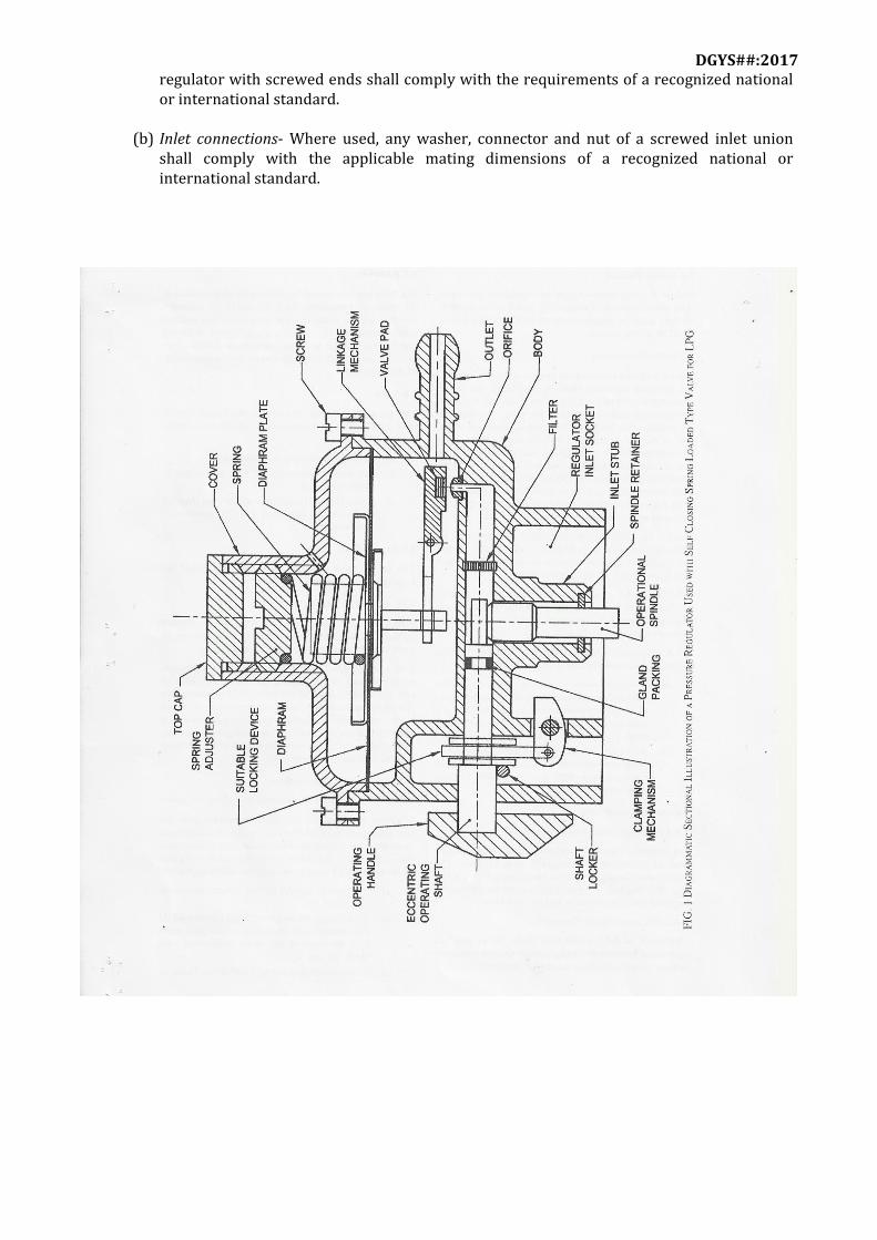
5 Construction and Workmanship 5.1 A typical regulator to match self-closing valve is shown in Fig. 1 for illustration purpose. 5.2 The regulator, including all the component parts, shall be mechanically strong, of sound construction and of high standard of workmanship and finish. 5.3 The components of a regulator shall be interchangeable with the corresponding components of any other regulator of the model and size. 5.4 Screw Thread Expect for the screwed ends of regulators not fitted with inlet or outlet connectors, screw threads shall comply with the requirements of a recognized national or international standard. 5.5 Inlet Connection Where screwed connection are not used, the inlet of the pressure regulator shall be cast integrally as an inseparable part of the body or so fixed that it cannot be separated without damaging the body. The size and the profile of the inlet connection shall match the outlet end of the spring actuated self closing valve of LPG cylinder to achieve a leak proof coupled joint without use of a resilient packing or washer or gasket as a part of the regulator. However, the use of a gasket or packing shall be permitted so long as there is a leak proof joint with the valve, with the help of the gasket or packing as a part of the valve. 5.5.1 The inlet connection shall be designed to withstand a minimum hydrostatic pressure of 1.5 times the saturated vapour pressure of the gas at 500C subject to a minimum of 18 kgf/cm2 for 120s. 5.5.2 The inlet connection shall also be capable to withstand a minimum pneumatic pressure equivalent to the maximum vapour pressure specified in 3.1 at ambient temperature. 5.5.3 Where screwed connections are used for inlet or outlet or regulator the following shall apply:
(a) Screwed ends- Where inlet or outlet connections are not fitted, the inlet and outlet of a
DGYS##:2017
regulator with screwed ends shall comply with the requirements of a recognized national or international standard.
(b) Inlet connections- Where used, any washer, connector and nut of a screwed inlet union shall comply with the applicable mating dimensions of a recognized national or international standard.

DGYS##:2017
5.6 Outlet Connection 5.6.1 Non-threaded Outlet Connection For regulators for domestic service the outlet nozzle shall be horizontal cast integrally with the body. The nozzle shall be any of the two specified in Fig. 2A and Fig. 2B. The choice of type shall be as per the agreement between the manufacturer and the purchaser, (provided that the LPG regulator meets the requirements of this standard) and subject to the approval of the regulatory authority. 5.6.2 Threaded Outlet Connection Threaded outlet connection shall be as per the agreement between the manufacturer and the purchaser (provided that the LPG regulator meets the requirements of this standard) subject to approval from statutory authority. 5.7 Body The body and cover shall be strong enough to withstand the stress of connecting the regulator to the cylinder valve or piping installation and to withstand normal stress imposed by service conditions, without developing leakage at joints, permanent deformation or other damage which might impair the serviceability of the regulator. 5.8 Vent The breather hole (air vent above diaphragm space) shall be of such size and at such location on the cover that: (a) it does not easily get clogged/blocked; (b) the accidental entry of foreign matter is minimized; and (c) it would be difficult for an instrument inserted through the air vent hole to reach the
diaphragm. 5.9 Excess flow Valve The excess flow valve, if provided shall meet the requirements given in Annex F. 5.10 Valve Pad Fitting 5.10.1 A valve pad (resilient) shall be so retained without the use of adhesive that it cannot loosen or work out of position under service conditions. 5.10.2 The inlet orifice and the valve pad of the pressure regulator shall be protected by provision of a filter of suitable material compatible with LPG, of appropriate size of perforations that does not hamper flow of vapour but is yet effective against ingress of contaminating agents in the gas. Any acceptable arrangement meeting this requirement, as agreed to between the manufacturer and the purchaser is permitted (provided that the LPG regulator meets the requirements of this standard). 5.11 Strength of the Connection/Regulator Assembly 5.11.1 The fixing of the inlet connection on to the regulator body, whether it is the threaded or non-threaded type or in one piece, shall withstand the following tests, under the conditions defined in 8.11 (see Table 1).

DGYS##:2017
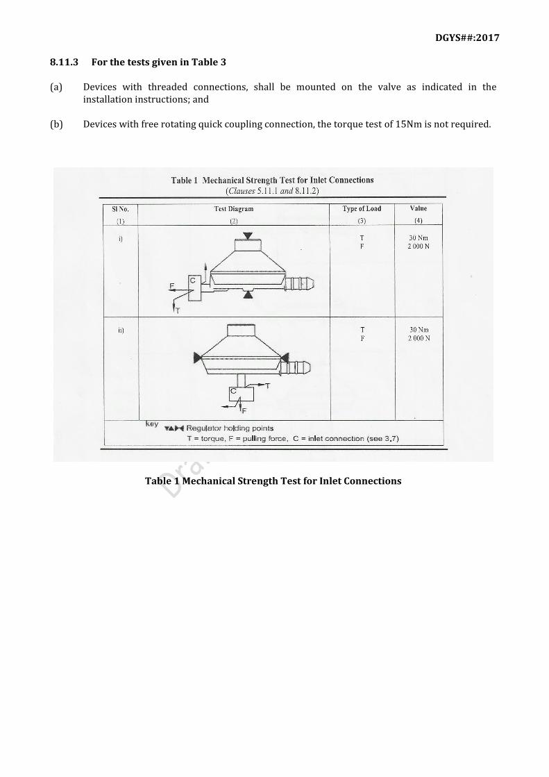
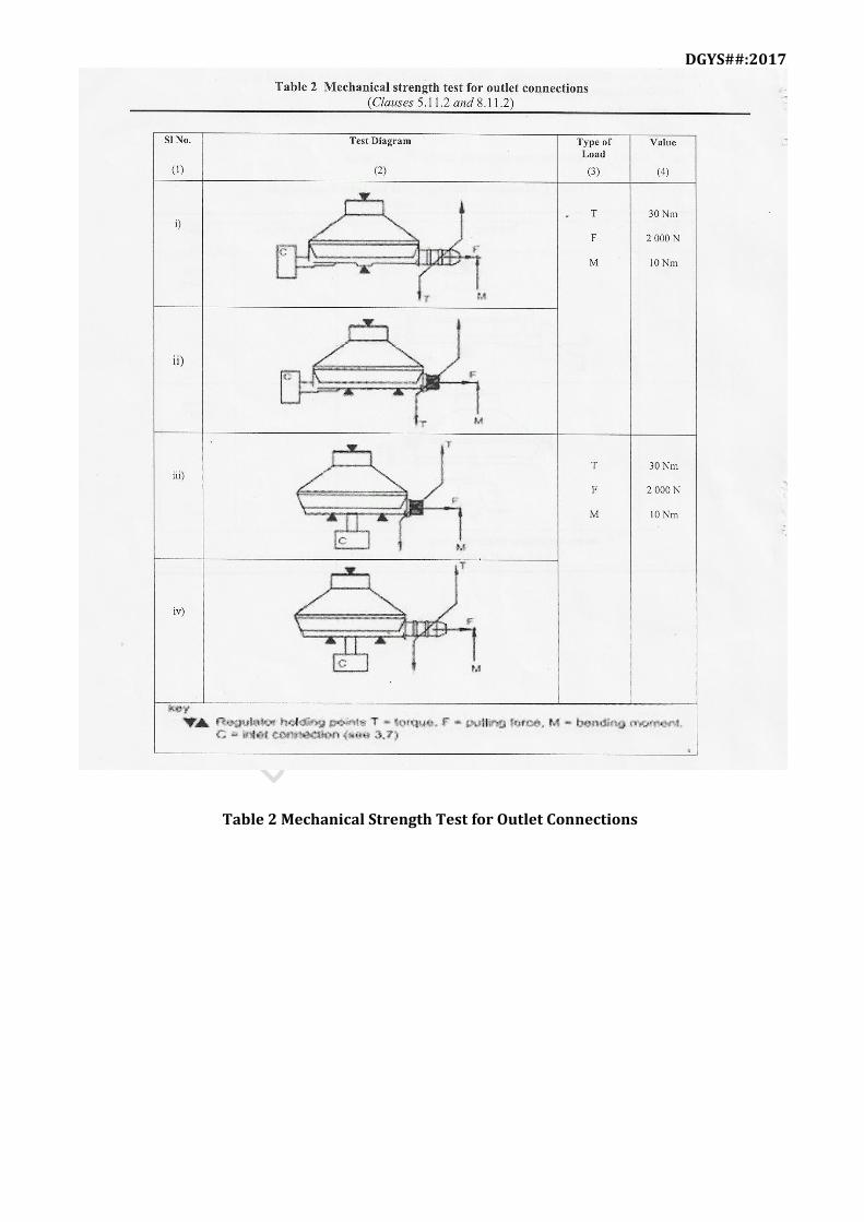
(a) A torque of at least 30Nm in both directions; and (b) A tensile strength test of 2000N 5.11.2 The fixing of the outlet connection on to the regulator body, whether it is the threaded, or non-threaded type or in one piece, shall resist the following tests, under the conditions defined in 8.11 (see Table 2): (a) For non-threaded hose connection:
(1) A torque of at least 30Nn in one direction (verification not required for freely rotating connection),
(2) Bending moment of 10 Nm, and
(3) A tensile strength test of 2000N.
(b) For threaded unions:
(1) A torque of at least 30Nm in both directions (verification not required for freely rotating connections),
(2) A blending moment of 10 Nm, and
7 (3) A tensile strength test of 2000N.
5.11.3 For freely rotating connections, the torque necessary for the rotation of the connection shall not be greater than 0.5 Nm at the end of all the tests carried out. 5.11.4 No distortion or breakage shall be evident and the regulations shall comply with the soundness test described in 6 after application of the forces. 5.12 Strength of Regulator Assembly when Fitted onto a Cylinder Valve 5.12.1 The regulators when installed as indicated in the installation instruction shall resist the following tests under the conditions defined in 8.11 (see Table 3): (a) A torque in both directions,
(1) of at least 20Nm for non-threaded hose outlet connections (15 Nm for quick coupling connections); and
(2) of at least 30 Nm for threaded outlet connections. In addition, regulators with screwed unions intended to be vertically mounted onto the cylinder valve, shall resist a torque of at least 20Nm in the regulator plane (15Nm for quick coupling connections).
(b) A bending moment created by a force of 400N directed upwards and whose application point
is at the base of the outlet connection, and (c) A tensile strength test of 500 N, for quick coupling connections only. 5.12.2 The mechanical strength required shall be ensured for all the positions of fixing of the regulator (as indicated in the installation instructions) onto the cylinder.

DGYS##:2017
5.12.3 There shall be no distortion or breakage that could affect the safety of the regulator. The regulator shall comply with the soundness test described in 6 after application of the forces.
6 Soundness 6.1 A regulator shall be considered leak tight when tested in accordance with 6.2 and if the leakage rate does not exceed 4 N mm3/s (the symbol N indicates conversion to normal temperature and pressure conditions, NPT that is 760 mm of Hg and 0 0C). 6.2 The regulator shall be leak tight when tested pneumatically at a pressure of 0.490 kN/m2 (5gf/cm2) below twice the nominal pressure when fitted with a relief valve or 14.70 kN/m2 (150gf/cm2) when not fitted with a relief valve, applied through the outlet connection of a fully assembled regulator and held for not less than 30 s and not more than 60 s after stability has been achieved. To get stability, adequate time is allowed between introduction of test medium and the start of observation, so that the internal parts have attained balanced positions. 6.3 Those parts of the regulator which are normally subjected to the full cylinder pressure shall be leak tight at a minimum hydrostatics pressure of 1.5 times the saturated vapour pressure of the gas at 650C or minimum 18 kgf/cm2, whichever is greater for a period of 120s. To ensure that the hydrostatic pressure and medium extends only in and up to the high pressure sections, a pneumatic

DGYS##:2017
back pressure not exceeding 14.70 kN/m2 (150 gf/cm2) is applied to the outlet connection of the regulator before the start of the test and is kept on throughout the test. Any change in the back pressure shall be construed as leakage through the pad/body and shall be treated as failure of the regulator. 6.4 Those parts of the regulator which are normally subjected to the full cylinder pressure shall also be tested for soundness at a pressure of 1.666 kPa (17kgf/cm2) for a period of not less than 30s and not more than 60s, after stability has been achieved. To ensure that the pneumatic pressure sections, a pneumatic back pressure not exceeding 14.70kN/m2 (150 gf/cm2) is applied to the outlet connection of the regulator before the start of the test and is kept on throughout the test. Any change in the back pressure shall be construed as leakage through the pad/body and shall be treated as failure of the regulator.
7 Range of Pressure Adjustment 7.1 The standard range of pressure adjustment, the range of inlet pressure and the range of outlet pressures is elaborated in 7.2 and 8.9.1. This does not precluded and specific requirement deviating from the standard, as may be agreed to between the manufacturer and the purchaser, provided that essentials of the standard ranges are maintained. 7.2 For the purpose of performance test of domestic service regulators, the standard range of inlet pressures for use with LPG, shall extend from 49 kPa (0.5 kgf/cm2) to 1666 kPa (17 kgf/cm2).
8 Setting and Performance 8.1 Test Gases The performance tests shall be carried out using air, after making due provision for a factor of conversion representing the flow of appropriate gas for which the regulator is designed, that is, butane, propane, or mixture for the equivalent vapour condition. The volume conversion factors for certain gasses are given below:
Multiply flow of By To obtain flow of
Air
0.707 1.290 0.808 0.75
Butane
Natural gas Propane
120 RVP Butane /Propane mixture
120 RVP
Butane/Propane mixture Butane
1.333
1.414 1.826 1.140
Air
Air Natural gas
Propane
Natural gas
0.775 0.547 0.625
Air
Butane Propane
DGYS##:2017
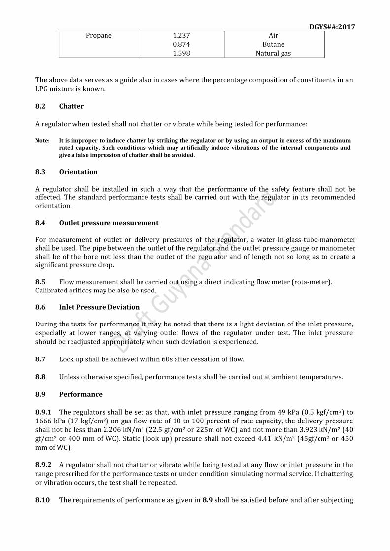
Propane 1.237 0.874 1.598
Air Butane
Natural gas
The above data serves as a guide also in cases where the percentage composition of constituents in an LPG mixture is known. 8.2 Chatter A regulator when tested shall not chatter or vibrate while being tested for performance: Note: It is improper to induce chatter by striking the regulator or by using an output in excess of the maximum
rated capacity. Such conditions which may artificially induce vibrations of the internal components and give a false impression of chatter shall be avoided.
8.3 Orientation A regulator shall be installed in such a way that the performance of the safety feature shall not be affected. The standard performance tests shall be carried out with the regulator in its recommended orientation. 8.4 Outlet pressure measurement For measurement of outlet or delivery pressures of the regulator, a water-in-glass-tube-manometer shall be used. The pipe between the outlet of the regulator and the outlet pressure gauge or manometer shall be of the bore not less than the outlet of the regulator and of length not so long as to create a significant pressure drop. 8.5 Flow measurement shall be carried out using a direct indicating flow meter (rota-meter). Calibrated orifices may be also be used. 8.6 Inlet Pressure Deviation During the tests for performance it may be noted that there is a light deviation of the inlet pressure, especially at lower ranges, at varying outlet flows of the regulator under test. The inlet pressure should be readjusted appropriately when such deviation is experienced. 8.7 Lock up shall be achieved within 60s after cessation of flow. 8.8 Unless otherwise specified, performance tests shall be carried out at ambient temperatures. 8.9 Performance 8.9.1 The regulators shall be set as that, with inlet pressure ranging from 49 kPa (0.5 kgf/cm2) to 1666 kPa (17 kgf/cm2) on gas flow rate of 10 to 100 percent of rate capacity, the delivery pressure shall not be less than 2.206 kN/m2 (22.5 gf/cm2 or 225m of WC) and not more than 3.923 kN/m2 (40 gf/cm2 or 400 mm of WC). Static (look up) pressure shall not exceed 4.41 kN/m2 (45gf/cm2 or 450 mm of WC). 8.9.2 A regulator shall not chatter or vibrate while being tested at any flow or inlet pressure in the range prescribed for the performance tests or under condition simulating normal service. If chattering or vibration occurs, the test shall be repeated. 8.10 The requirements of performance as given in 8.9 shall be satisfied before and after subjecting

DGYS##:2017
the regulator to tests specified in 8.10.1, 8.10.2 and 8.10.3. Deviation in the initial setting, after these tests, is acceptable. If the regulator is fitted with excess flow check device, the performance of the excess flow valve shall also be checked as per Annex F. 8.10.1 Cycle Test When assessing a new design, a type approval test in accordance with Annex G shall be carried out. A fully assembled regulator shall withstand a minimum of 100 000 cycles of opening and closing operations, after which it shall be subjected to a soundness test as in 6.2, 6.3, 6.4 and performance as given in 8.9. 8.10.2 Low Temperature Test The regulator is exposed to a temperature of -200C for a minimum period of 10 min for the complete assembled unit to attain this temperature. It is then removed and left exposed to ambient conditions, after which it is tested. The method of carrying out the test shall be as per Annex H. If the regulator is fitted with excess flow check device, the performance of the excess flow check valve shall also be checked as per Annex F. 8.10.2.1 Heating shall not be applied to reach the ambient temperature. 8.10.2.2 Care shall be taken to avoid intrusion of fluid or moisture into the regulator assembly during cooling and recovery. For this the outlet nozzle, the inlet and the breather hole may be plugged.
11 8.10.3 High Temperature Test The regulator is exposed to a temperature of 650C for a minimum period of 10 min for the complete assembled unit to attain this temperature. It is then removed and left exposed to ambient conditions, after which it is tested. The method of carrying out the test shall be as per Annex H. If the regulator is fitted with excess flow check device, the performance of the excess flow check valve shall also be checked as per Annex F. 8.10.3.1 Forced cooling shall not be applied to reach the ambient temperature. 8.10.3.2 Care shall be taken to avoid intrusion of fluid or moisture into the regulator assembly during heating and cooling. For this the outlet nozzle, the inlet and the breather hole may be pugged. 8.11 Mechanical Strength of Connections 8.11.1 General Tests for mechanical strength shall be carried out using a dynamometric device allowing the measurement of forces to within ± 5 percent accuracy. For the torque test, a system which neutralizes bending moments shall be used (if a torque wrench is used it is desirable that this is double handed). The duration of application of the torques, moments and forces shall be 60s each. 8.11.2 Regulator intended to be Directly Connected to a Cylinder Valve The points where the device is held and the test values are those shown in Table 1, 2 and 3.
DGYS##:2017
8.11.3 For the tests given in Table 3 (a) Devices with threaded connections, shall be mounted on the valve as indicated in the
installation instructions; and (b) Devices with free rotating quick coupling connection, the torque test of 15Nm is not required.
Table 1 Mechanical Strength Test for Inlet Connections
DGYS##:2017
Table 2 Mechanical Strength Test for Outlet Connections

DGYS##:2017
Table 3 Mechanical Strength Test for Device Assembly mounted on the Cylinder Valve
DGYS##:2017
9 Sealing 9.1 If the regulator is permanently not crimped, the body and the cover of each regulator shall be sealed to discourage interference with the internal mechanism as well as the pressure setting. 9.1.1 The manner of sealing shall be as agreed to between the purchaser and the manufacturer (provided that the LPG regulator meets the requirements of this standard).
10 Classification of Tests 10.1 Type Tests The following shall constitute type test out of the various requirements: (a) Diaphragm material (see4.3); (b) Valve pad material (see 4.4); (c) Hydrostatic test (see 6.3); (d) Low and high temperature tests (see 8.10.2 and see 8.10.3); (e) Mechanical strength of connection (see 8.11); and (f) Tests for excess flow device, if provided (see 5.9). 10.2 Routine Tests The following shall be carried our as routine tests: (a) Pneumatic test (see 6.2 and 6.4); and (b) Chatter and performance test (see 8.9).
11 Marking 11.1 A Regulator shall be clearly and permanently marked with the following: (a) Manufacturer or distributer’s name or trade mark; (b) Month and year of manufacture (for example 12 -10 for December 2010); (c) Rated capacity, in m3/h of LPG; (d) Certification or standards mark from a body recognized by the GNBS; and (e) Any other markings as agreed to between the purchaser and the manufacturer. 11.2 LPG regulators shall be accompanied with instructions for use in English. These shall be
affixed to the regulator, contained within the package of the regulator; or on the package of the regulator.

DGYS##:2017
Annex B (Clause 4.2.1)
Method of Test for adhesion of paint B-1 A square measuring 12 to 15 mm sides shall be marked on plain surface (not having raised or sunk markings) of randomly selected specimen from the lot of painted or powder coated components. Cross lines at a distance of 1 to 1.5 mm and inched at approximately 1200 angle with each other shall be described over the marked portion with a sharp pointed instrument, cellulose tape shall be applied over this portion and left for 2 min after which shall be jerked free from the surface under test. If a more than 3 percent of the squares are ripped from the surface under test. The specimen shall be deemed to have failed test.
Annex C (Clause 4.3.4)
Bursting and pull out test of diaphragm in an assembled regulator C-1 General C-1.1 The test is designed to give a practical result on assembled regulator, and is intended as simple check method which may be applied by the regulator manufacturer to diaphragm material which shall usually have been previously tested. C-1.2 The test takes the form of a simple application of pressure (air or nitrogen is suitable) through the outlet connection the underside of the diaphragm mounted in a regulator in fully assembled condition (that is, as it would be supplied by the manufacturer to a buyer). C-2 Test Rig C-2.1 The outlet of the assembled regulator is connected to a supply of air or nitrogen. C-2.2 A gauge is incorporated in the test rig between the air or nitrogen supply and the regulator to indicate the applied pressure. C-3 Test Method The pressure is applied at approximately 78 kPa (0.8 kgf/cm2) per second up to the level specified in 4.3.4 and maintained for 120 s.
DGYS##:2017
Annex D (Clauses 4.3.5 and 4.4.2)
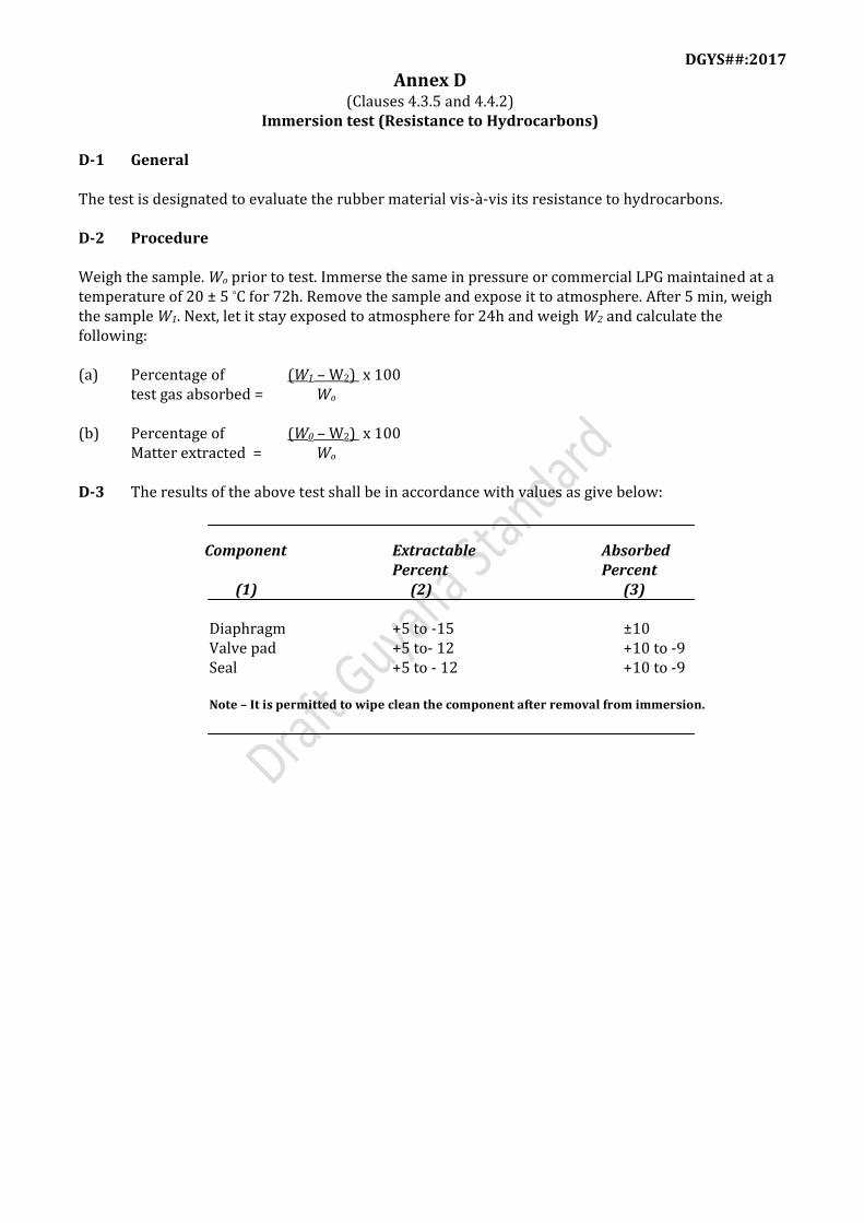
Immersion test (Resistance to Hydrocarbons) D-1 General The test is designated to evaluate the rubber material vis-à-vis its resistance to hydrocarbons. D-2 Procedure Weigh the sample. Wo prior to test. Immerse the same in pressure or commercial LPG maintained at a temperature of 20 ± 5 °C for 72h. Remove the sample and expose it to atmosphere. After 5 min, weigh the sample W1. Next, let it stay exposed to atmosphere for 24h and weigh W2 and calculate the following: (a) Percentage of (W1 – W2) x 100 test gas absorbed = Wo (b) Percentage of (W0 – W2) x 100 Matter extracted = Wo D-3 The results of the above test shall be in accordance with values as give below: Component Extractable Absorbed Percent Percent (1) (2) (3) Diaphragm +5 to -15 ±10 Valve pad +5 to- 12 +10 to -9 Seal +5 to - 12 +10 to -9 Note – It is permitted to wipe clean the component after removal from immersion.

DGYS##:2017
Annex E (Clauses 4.3.7 and 4.4.5)
Method of compression set test for valve pad material, seal and diaphragms E-1 General The test is designated to differentiate between the original thickness of the tests piece and that after recovery, expressed a percentage of the initial applied compression. E-2 Procedure Three mono-block test piece disc of 13±0.5mm diameter and 6.3±0.3mm thickness shall be tested subject to the following conditions: (a) Compression : 25% at (27 ± 2oC) (b) Duration of test : 168 +0 -2h for valve pad and seal material and 24 ± 0.5h for diaphragm (c) Test temperature : 70 ± 1oC E-3 Calculation Calculate the compression set expressed as a percentage of the initial deflection from the following formula: Compression set, percent = t0 – t1 x 100 to – t8 where to = initial thickness of the test piece, in mm; t1 = thickness of the test piece after recovery in mm; and t8 = height of the spacer; in mm. The results for the three test pieces shall agree within 5 percent of the mean compression set value; if they do not, the test shall be repeated.

DGYS##:2017
Annex F (Clauses 5.9 and 8.10)
Regulators fitted with an excess flow check valve F-1 General The excess flow check valve is device integral with the regulator which causes the shut off of the gas flow for values of flow rate above the rated capacity of the regulator. In the case of a manual device the regulator device allowing the restoration of the flow can be a re-setting device or a valve generally appropriate for this type of regulator. F-2 Performance characteristics The excess flow check valve shall shut-off the gas flow in all the cases of disconnection of the flexible hose or tube fitted down stream of the regulator. This device shall operate for an increase in the rate between 120 percent and 200 percent of the rated capacity of the regulator at an angle of ±10o relative to its axis in the fixing position(s) of the regulator in the range and the rate obtained on hose or tube disconnections of minimum (-200C) and maximum temperature (+650C) conditions. The restoration of the gas flow shall only be possible by manual intervention when the conditions which caused the safety devices to operate have disappeared. For manual resetting devices a maximum residual leak of 15cm3/h is permitted. The regulator fitted with excess flow valve in shut-off condition shall be checked for any leakage. The regulator shall be connected to the bubble indicator through a flexible pipping (see fig.3). The regulator shall be subjected to full inlet pressure and examine the bubble indicator for the appearance of the bubbles. The interval between successive bubbles passing through it shall not be less than 10s. The presence of the device shall not modify the regulator performance. F-3 Test Method- Additional tests for the regulator The closure caused by excess flow check valve shall be obtained in the range defined between 120 percent and 200 percent of the rated capacity of the regulator. For the endurance test the device shall be subjected to a series of 100 cycles of opening/closing operations without change in operating force, sensitivity of positioning device and without apparent traces of pitting. This test shall be carried out at ambient temperature. F-4 User and Maintenance instructions In addition to the regulator working instructions the manufacturer shall clearly indicate in the instructions the following information: (a) Do not move the cylinder during the use. (b) Switch off in the event of operation of the excess flow valve. (c) Only turn on the regulator after having rectified the cause of the device operating. (d) Instructions on manual resetting of the excess flow check valve. For the purpose of routine test the regulator when checked the excess flow check valve shall shut off

DGYS##:2017
the gas flow in all the cases of disconnection of the flexible hose fitted down stream of the regulator.
Fig 3. Buddle Indicator
Annex G (Clause 8.10.1)
Cycle Test (Endurance Test) G-1 The purpose of the test is to evaluate the quality of various flexibles, such as valve pad, diaphragm and spring, vis-à-vis retention of critical properties relevant to function, resistance to deformation/degradation, loss of flexibility under conditions of flexing and unflexing. This test does not purport to check any mechanical requirements of the construction/assembly and should not be taken as representative of actual service conditions and could introduce improper parameters of assessment of non-flexibles. The test should relate only to the flexibles referred to above. G-2 The regulator is mounted on a valve or suitable inlet connection (whose outlet matches with the inlet of the regulator). The outlet of the regulator is connected to a system which shall indicate flow or lack of it (that is, a burner, flow meter or orifice in parallel with a pressure indicating device such as a manometer column). Air/gas is introduced into the regulator at an appropriate pressure in such a manner that the diaphragm gets flexed and the valve pad is held on its seat for a minimum of 1 s, after which the inlet is shut-off and the air/gas is vented via the outlet of the regulator to atmosphere. G-2.1 One example of a set up to carry out this test is install quick acting valves upstream and downstream of the regulator, wherein the downstream valve exhausts to atmosphere. The valves are connected to a suitable time switch so that as one opens, the other closes; with a complete cycle time

DGYS##:2017
of approximately 5s. G-2.2 Any other set up producing equivalent conditions and achieving the same objectives would be acceptable. G-3 After completion of the test mentioned in G-2, the regulator shall meet the requirements of soundness test as in 6.2, hydrostatic test as in 6.3 and performance as in 8.9.1. However, with the static (lock up) pressure not exceeding 110 percent of that allowable in relevant lock up clause. Note:-If the tests are carried out using LPG vapour as test medium, sufficient precaution should be ensured to vent inflammable gas to environments where there should be no danger of fire. Alternatively, the venting could be done via gas burning devices.
Annex H (Clauses 8.10.2 and 8.10.3)
Low temperature and high temperature tests H-1 Low temperature test A fully assembled regulator, set as in 8.9 is placed in a sealed container and this container is immersed in a bath of any convenient fluid (namely, methanol or any suitable freezing mixture like salt+ ice+ calcium carbide) cooled to a steady temperature at -200C and maintained at this temperature by some reliable means (by additions of dry ice). It is kept immersed long enough for the complete assembly to attain – 200C (10 min) after which it is removed and exposed to the atmosphere so that the assemble returns to ambient conditions. It is then tested in accordance with 8.9 for performance. Note:-Care should be taken to prevent the cooling fluid entering the assembly or of moisture condensing inside. This may be avoided be ensuring that the sealed container lid opened only after the assembly attains ambient conditions.
H-2 High temperature test A fully assembled regulator set as in 8.9 is placed in a sealed container and this container, if placed in a bath of water heated to a steady temperature of 650C. It is kept immersed long enough for the complete assembly at attain 650C (10 min) after which it is removed and exposed to atmosphere so that the assembly returns to ambient conditions. It is then tested in accordance with 8.9 for performance. Note:-Care should be taken to prevent the bath water from entering the assembly, or of moisture forming inside. This may be avoided by ensuring that the sealed container is opened only after assembly attains ambient conditions. Also, air shall not be forced through the assembly in an attempt to accelerate cooling as this is likely to result in condensation of moisture inside the assembly.