Download Wireless Guide - Pacific Crest
48
The Guide To Wireless GPS Data Links Pacific Crest Corporation 990 Richard Avenue Suite 110 Santa Clara California 95050 USA Tel 408 653 2070 Fax 408 748 9984 www.paccrst.com
Transcript of Download Wireless Guide - Pacific Crest

The Guide To
Wireless GPSData
Links
Pacific Crest Corporation990 Richard Avenue Suite 110 Santa Clara California 95050 USATel 408 653 2070 Fax 408 748 9984 www.paccrst.com

Notice
©2000 by Pacific Crest Corporation. All rights reserved.
No part of this book may be reproduced inany form without permission in writing fromPacific Crest Corporation.
All Pacific Crest Corporation products aretrademarks or registered trademarks ofPacific Crest Corporation. Other brand andproduct names are trademarks or registeredtrademarks of their respective holders.
Printed in the United States of America.
First Edition – May 1995Second Edition – October 1995Third Edition – September 2000
T h e G u i d e t o W i r e l e s s G P S D a t a L i n k si

Notice i
Table of contents ii
Introduction iii
Maximize the performance of your DGPS RTK system 1
Basics 4Radio wave propagation 5Terminology 6General rules 6VLF, LF, and MF radio signal propagation 6HF radio signal propagation 7VHF radio signal propagation 7UHF radio signal propagation 8Modulation 9Data communication 9Antennas 10
Performance issues 13RF power 14Line and system losses 15Path loss 16Antenna gain 17Receiver sensitivity 18Fade margin and multi-path 19
Estimating system performance 20UHF/VHF range calculations 21FEC and data scrambling 23Fade considerations 25
FCC licensing and regulations 26Licensing requirements 27Application forms 27Frequencies 27Technical issues 28How to get help 29
RFDC applications 30Point-to-point 30Digipeater 31Packet operation 32
Appendix A Glossary 33
Appendix B Bibliography 37
Appendix C Frequency coordinators 38Public safety radio services 38Industrial radio services 39Industrial radio groups 40Other land transportation radio services 40Other frequency pools 41
Index 42
conte
ntsT h e G u i d e t o W i r e l e s s G P S D a t a L i n k s
Table of
ii

This Guide has been written specifically for the surveyor to provide useful information about wirelesscommunication. The first section offers tips and techniques for maximizing the performance of your DGPS RTK(Differential Global Positioning System Real Time Kinematic).
The remainder of this Guide isdesigned to provide a basic nuts-and-boltsawareness of the issues and tradeoffs concerning radio frequency data communication (RFDC). The objective is to provide the surveyor with the skills andknowledge required to successfully estimatethe data link requirements, set up the datalink, and to diagnose and fix problems that are common to these systems. Thoseinterested in further understanding of the technical or academic aspects of RFDCshould refer to the bibliography inAppendix B.
Before beginning, a few simplepoints. Radio data communication is not difficult or mysterious. Detailed knowledgeof data and radio communication theory isnot required. With an understanding of afew basic principles, you can design and setup an RFDC link that will provide reliabledata communication.
Naturally, the physical laws ofnature place bounds on what can be expected of an RFDC system. Recognizingthese bounds and knowing some basic rules-of-thumb is the goal of this course. You will find throughout this book, textboxes which highlight things to do or thingsto avoid. Following these simple rules willallow you to get the most out of your RFDCsystem.
Introduction
T h e G u i d e t o W i r e l e s s G P S D a t a L i n k siii
Getting the most out of your
real-time differential GPS
system is a challenge.
While GPS technology
offers tremendous potential
and is increasingly easy to use,
there are still some aspects
that require a basic degree of
understanding.
This guide focuses on
the radio data link. The radio
data link passes correction
information from a stationary
GPS reference station to the
rover.
In this chapter we
present the best of what we’ve
learned through almost a decade
of providing radio links for
survey applications.
Maximizethe performance
of your DGPS RTK system
1
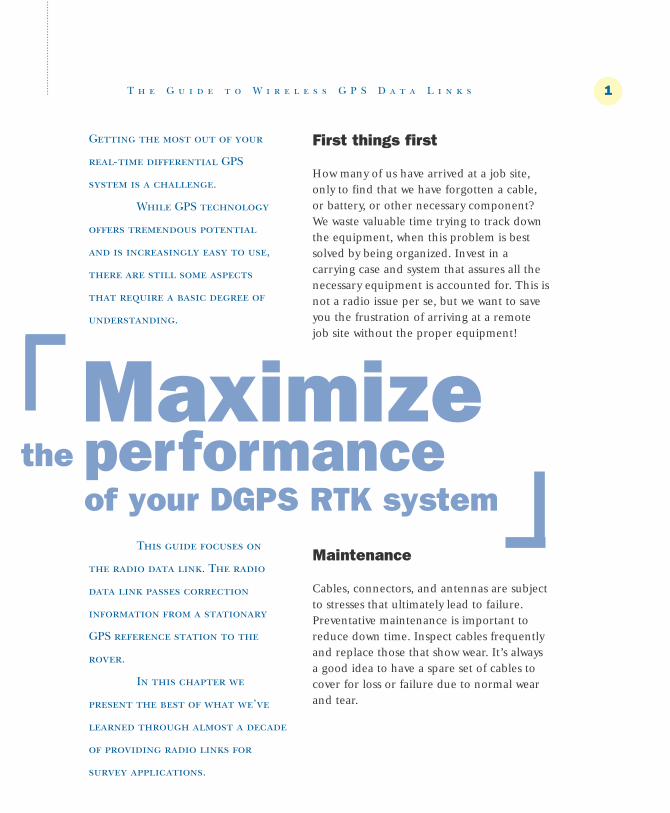
First things first
How many of us have arrived at a job site,only to find that we have forgotten a cable,or battery, or other necessary component?We waste valuable time trying to track downthe equipment, when this problem is bestsolved by being organized. Invest in a carrying case and system that assures all thenecessary equipment is accounted for. This isnot a radio issue per se, but we want to saveyou the frustration of arriving at a remotejob site without the proper equipment!
Maintenance
Cables, connectors, and antennas are subjectto stresses that ultimately lead to failure.Preventative maintenance is important toreduce down time. Inspect cables frequentlyand replace those that show wear. It’s alwaysa good idea to have a spare set of cables tocover for loss or failure due to normal wearand tear.
T h e G u i d e t o W i r e l e s s G P S D a t a L i n k s

Select the best available channel
Surveyors often operate over a wide areadepending on the type of firm. If you workin a fixed location, a coordinated frequencyis best used. For those who move about, the use of itinerant frequencies is called for. When you enter a new location, it’simportant to select a channel that minimizesinterference with other users (and subsequent complaints), as well as one thatprovides the best operation. There are technologies available to help select the bestchannel for operation given conditions atthe outset of the survey – AutoBase™ andAutorover™ help you select an appropriatechannel.
The table below summarizes thepoints made in this chapter. You will improveyour level of success and satisfaction by following these simple rules.
Batteries
Batteries are another concern. Especially inareas where high powered radio modems are used, the condition and degree ofcharge are critical for best operation. Onlyuse batteries that are designed for deep discharge and frequent charging. Keep inmind that batteries degrade over time.Depending on usage patterns, you shouldreplace your battery every one to three years.
Picking a location
Radio link range is directly related to antenna height. The best thing you can doto improve your system range (a commoncomplaint) is to get your base station androver radio antennas as high as possible. Ifpossible, select a base station location thattakes advantage of terrain, and make use oftelescoping masts to improve range in all circumstances.
Use quality antennas
If you want superior performance, demand a high-quality antenna. Next to antennaheight, having a good antenna is the mosteffective and inexpensive way to improve system performance. Cheap, rubber duckantennas are okay for short-range site surveys, but if you want the best possible performance, invest in a high-performanceantenna. Our technical assistance staff canmake recommendations for you dependingon your application.
2 T h e G u i d e t o W i r e l e s s G P S D a t a L i n k s
1. Keep your equipment organized –
a carrying case is helpful.
2. Inspect and replace cables and
batteries before they fail.
3. Maintain spares of cables and other
equipment prone to failure through normal
wear and tear.
4. Select a location that takes
advantage of terrain – the higher the
better. Make use of antenna masts to get
your antennas higher, especially in
challenging base station locations.
5. Use high quality antennas. Rubber
duck antennas are not for high
performance systems.
6. Monitor and select an appropriate
channel to minimize interference with
other users.

One last note
Surveyors doing RTK work are members of a greater community that share the radiospectrum. In order to maintain access to thisvital spectrum, it’s important that we allunderstand and follow our obligations aspart of this community.
Get a license
You are legally required to license your narrow-band radio modem system. We canrecommend a licensing service that will helpyou with the paper work and the applicationprocess. (See section on Licensing andRegulations). If you operate without alicense, you are subject to fines and possible equipment confiscation.
Turn off your radio when not in use
Never leave your base station broadcastingwhen you are not using the signal.Continuous operation, especially on itinerant applications, may lead to co-channel user complaints. Remember, data is secondary to voice in the itinerantbands. This means that if there’s a conflict,you (the data user), are obligated to vacatethe frequency.
Limit output power
If you’re doing a local area survey on a construction site or other short range application, limit your RF output power by selecting low power setting for yourequipment.
Select a channel with the least activity
This is common sense. Use AutoBase™ ormonitor the available channels prior to operation and select the channel with theleast activity.
Get along with co-channel users
If there’s a complaint from a co-channeluser, move to another frequency. If you operate out of a fixed location, then coordinate a frequency specifically for your use. You will not be given an exclusivefrequency, but you will be placed on a frequency that is appropriate for your activity.
T h e G u i d e t o W i r e l e s s G P S D a t a L i n k s 3

Understanding the basics of
RFDC provides a foundation
for successful implementation
of radio data communication
systems.
In this
section, the
fundamentals are
addressed in
layman’s terms, beginning with
the concepts of radio signal
propagation.
At the end of this section,
you should be familiar with some
common radio terms, and have a
basic understanding of radio
transmission theory including
data communication.
Basics
T h e G u i d e t o W i r e l e s s G P S D a t a L i n k s
Figure 1 – Electromagnetic spectrum
1 x 10⁻⁴ .01 1 100 10,000 1 x 10⁶ 1 x 10⁸ 1 x 10¹⁰ 1 x 10¹² 1 x 10¹⁴ 1 x 10¹⁶
CosmicRays
GammaRays
XRays
UltraViolet Infrared
Radio or Hertzian Waves
PowerLightV
isib
le
Indu
ctio
nH
eatin
g
Wavelength in Angstrom Units
4

at VHF frequencies between 88 and 108MHz (check your radio dial). AM radiosoperate at a much lower frequency in theMF band from 530 to 1700 kHz. Televisionstations operate at various frequencies in the VHF and UHF bands. Cellular phonesoperate in the 800 MHz region of the UHF band. We live in a world bathed in electromagnetic energy from television,radio, cordless phones, microwaves, and
visible light.Most
radio frequencybands are divided intochannels, each of which may beused to transmitvoice, data, or signalinginformation.RFDC systemsmake use of discrete radiochannels whereinformation is communicatedby modulation of the radio carrier. Thereare other
mediums and techniques used to communicate data usingthe electromagnetic spectrum, includingfiber-optics, infra-red, spread-spectrum, and others. These are beyond the scope of this book and will only be mentioned in passing.
Radio wave propagation
Radio waves are part of the electromagneticspectrum which encompasses visible light, x-rays, ultra-violet radiation and microwaves(see Figure 1). Electromagnetic waves travelat roughly the speed of light and have wavelengths which are related to the frequency of the wave. The table belowshows the spectrum of frequencies which are considered radio waves and their classifications:
We’re all familiar with portions of the radio spectrum that many of us use on a daily basis as we communicate, work, or relax. You may have enjoyed music or listened to news on your car radio on theway to work this morning. FM radios operate
T h e G u i d e t o W i r e l e s s G P S D a t a L i n k s
Frequency Wavelength Classification
10 - 30 kHz 30km - 10km Very Low Frequency (VLF)
30 - 300 kHz 10km - 1km Low Frequency (LF)
300 - 3000 kHz 1km - 100m Medium Frequency (MF)
3 - 30 MHz 100m - 10m High Frequency (HF)
30 - 300 MHz 10m - 1m Very High Frequency (VHF)
300 - 3000 MHz 1m - 10cm Ultra-High Frequency (UHF)
3 - 30 gHz 10cm - 1cm Super-High Frequency (SHF)
30 - 300 gHz 1cm - .1cm Extremely-High Frequency (EHF)
Table 1 – Radio spectrum classifications
5

6
Terminology
Before describing the characteristics of thedifferent radio bands, let’s review some basicradio terminology (refer to the glossary inAppendix A for an extensive listing of radioterminology). The following terms will beused in the sections which follow and shouldbe understood.
propagation: The path and manner which a radio wave travels from its source(the transmitter) to its destination (thereceiver). The path (often called “mode”) of propagation differs depending on the frequency of the radio signal. Also dependent on frequency is the reflection or refraction of the radio signal as it passesthrough layers of the ionosphere or as itreflects off of objects in its path.
range: The distance at which radio communication is adequate for a particular task. Voice communication is acceptable with noise or interference conditions which would make data communication unreliable.
coverage: The ability of the radio signal tobe available within the expected range butwhere the signal is blocked by man-made ornatural structures.
General Rules
A few generalities can be made about radiocommunication. Lower frequencies providebetter range than higher frequencies. Lower frequencies are more susceptible tointerference than higher frequencies.Coverage and signal penetration is better athigher frequencies than at lower frequencies.Most reliable data communication dependson line-of-sight conditions where the range islimited by the radio horizon. Figure 2 belowillustrates a line-of-sight transmission.
VLF, LF, and MF radio signalpropagation
This portion of the spectrum does not offerchannels available for data communicationexcept in a few special cases. Signals in these
T h e G u i d e t o W i r e l e s s G P S D a t a L i n k s
Curvature of the Earth
Line of sightAntenna Antenna
Figure 2 – Direct wave propagation "line-of-sight"

Earth
Skip
Ionosphere
bands have exceptional range but sufferfrom man-made and environmental noisewhich would limit data transmission in mostcircumstances to very low rates (<300 bitsper second). Some radio navigation beaconsoperating in the 285 to 325 kHz range provide 200 baud data DGPS corrections for marine based navigation. These beacontransmitters provide ranges in the hundredsof miles.
HF radio signal propagation
HF radio signals provide excellent range, but suffer low reliability for data communication because of co-channel interference from distant radio stations and susceptibility to man-made noise. TheFCC has allocated channels in the upperportion of the HF band starting at 25 MHz.Another mode of propagation for HF signalsis via ionosphere reflection. At these frequencies, the radio signal will reflect offof the ionosphere and travel back to theearth. See Figure 3 above. This "sky-wave"
propagation from distant radio stations isdifficult to predict, and is often influencedby the time of day and year, and the activityof sun-spots. Because of these various phenomena, HF data communication is limited to low baud rates and questionablereliability.
The higher the frequency the lowerthe influence of man-made noise and the co-channel interference caused by sky waveinterference (also called “skip”).
VHF radio signal propagation
While not entirely eliminated, problems ofsignal skip and susceptibility to interferencefrom man-made and environmental noiseare minimized in the VHF spectrum. Goodsignal coverage is provided but at a some-what shorter range than can be achieved inlower bands. VHF frequencies above 100MHz (high band) provide characteristics
T h e G u i d e t o W i r e l e s s G P S D a t a L i n k s
Figure 3 – HF signal propagation via "skip"
7

which make them adequate for moderate or high speed data communication. Theavailability of channels in the VHF highband (150 to 174 MHz ) for non-voice radiocommunication provide capabilities fortransmitting data in excess of 19,200 bits per second.
VHF high band and higher frequency radio signals are considered totravel in a line-of-sight (also called directwave) mode with minimal problems fromskip and noise. Line-of-sight propagationmeans that the range of the radio link is limited by the radio horizon, being the pointat which the curvature of the earth blocksthe signal between the transmitting andreceiving antennas.
On rare occasions, VHF signals may propagate in a mode called “ducting.”See Figure 4 above. This occurs when a temperature inversion provides atmosphericconditions such that the radio signalbecomes trapped between layers in theatmosphere. The radio waves travel in the“duct” and may propagate for long distances.Naturally, this is not a reliable mode of
propagation and may be a source of interference with distant radio transmissionsinterfering beyond their normal range ofinfluence.
UHF radio signal propagation
The UHF frequency band provides a goodcompromise for radio data communicationswhere range and data throughput arerequired. Signal skip and ducting are minimal, and the susceptibility to noise,including co-channel interference is mucheasier to control. Radio coverage is excellentwith penetration into buildings and over terrain better than at lower frequencies.Propagation is direct wave limited by theradio horizon. Problems associated withman-made noise are minimal.
At UHF and higher frequencies,care must be taken to minimize system losseswhich increase as the frequency increases.Also, at higher UHF frequencies andmicrowave frequencies, attenuation throughfoliage and caused by meteorological conditions must be considered.
T h e G u i d e t o W i r e l e s s G P S D a t a L i n k s
Earth
Normal Wave Range
Figure 4 – VHF signal propagation via "ducting"
8

Modulation
The modulation of the radio signal provides the ability to communicate information. Modulation is adding information to a radio wave by modifyingone of its fundamental characteristics. The fundamental characteristics of radiowaves are frequency, phase, and amplitude.
Different modulation schemes have been devised which make use of varyingthe frequency (frequency modulation),amplitude (amplitude modulation), andphase (phase modulation). These termsshould be familiar to radio listeners whotune in frequency modulated (FM) or amplitude modulated (AM) radio stations.Figure 5 here shows the different modulating waveforms of a basebandsignal. The baseband signal is the actual datawhich is represented by a serial stream of 0’s and 1’s.
The type of modulation and suitabilityof a modulation for a particular application isbeyond the scope of thiscourse material. Most modern high-speed datalinks use one of the formsof frequency modulationwhich is spectrally efficientand provides immunityfrom variations in signalstrength known as fade(more on this later).
Data communication
Data communication over radio waves provides an efficient and reliable transfer of information. Because of the limited spectrum available for communication, more and more digital systems are being utilized. In comparison to voice communication, the amount of informationtransferred over a radio link via modulateddata is astounding. Because of this, traditional users of voice communication in the public safety sector (police, fire, search-and-rescue) are turning to radio data communications to provide dispatch and other information.
Data communication is
T h e G u i d e t o W i r e l e s s G P S D a t a L i n k s
1 0 1 0 1
Baseband
AmplitudeModulation
(AM)
PhaseModulation
(PM)
FrequencyModulation
(FM)
t
t
t
t
Figure 5 – Modulation waveforms
9

fundamentally similar to voice communication in the manner in which the radio signal is modulated. Most modernvoice and data communication systems inthe UHF and VHF commercial bands makeuse of frequency modulation, althoughamplitude modulation is common in somemarine and aviation applications. For voicecommunication, the audio signal is pickedup by the microphone and changed into avarying voltage level. The voltage level isapplied to the radio transmitter to modulatethe carrier frequency. The radio receiver in a voice system takes the modulated frequency and produces a signal which replicates the signal from the transmitter,which is then applied to a speaker producing audio output.
Data communication is performedby encoding the digital signal on an analogwaveform which is capable of being passedvia radio modulation. Digital signals arecomposed of groups of binary data consisting of 0’s and 1’s which representnumbers, or characters (called bytes). Thestream of 0’s and 1’s which make up the digital message are shifted through a modulator which produces an analog waveform which represents the data. Thissignal, called the baseband modulation, isdesigned to provide a signal waveform thatcan be transmitted and received by the radiohardware. High speed data requires specialfiltering to assure that the data modulatedcarrier fits within the channel spacing mandated by the FCC.
A measure of how good a communication system can transmit data is ameasurement of the Bit Error Rate (BER). A bit error occurs due to interference or low
T h e G u i d e t o W i r e l e s s G P S D a t a L i n k s
signal levels where a bit as sensed by the receiver is not correct. The BER is the ratio of bit errors to the total number of bits transmitted. For valid comparisons of radiodata systems, the BER must be measured within the context of a total system thatincludes low signal levels and fade conditions.
Sophisticated RFDC equipment usesForward Error Correction (FEC) protocolswhich allow errors in the received data to becorrected. Because of the nature of RFDC, an FEC algorithm should be chosen whichworks well in the correction of burst bit errorsas opposed to single bit errors.
Antennas
Selection and proper installation of the antenna system often makes the differencebetween a reliable and robust or an unreliable data communication system. The antenna is the radiating element whichtakes the RF energy generated by the radioand begins its propagation through space.Antennas come in a variety of sizes and shapes designed for specific uses.
The ability to focus the RF energy in a specific pattern provides a method foroptimizing the coverage and range of the communication network. Some antennas are highly directional and allow the use of relatively low power radio transmitters to send data over long distances. Other antennas are designed for omni-directional use where the relationship between the transmitter and receiver is constantly changing. The nature of the communicationactivity normally dictates what sort of antennato use (directional or omni-directional).
10

T h e G u i d e t o W i r e l e s s G P S D a t a L i n k s
The most important activity in setting up a radio transmitter is determiningthe placement and type of the antenna.Where flexibility permits, always place theantenna on the highest point available andalways select an antenna with a gain pattern(more on this later) which optimizes the coverage. In general, use a directionalgained antenna such as a Yagi for a point-to-point fixed location application and a gained omni-directional antenna formobile point-to-point or point-to-multipointcommunication systems. See Figures 6and 7 here.
Antenna
Horizontal Gain Vertical Gain
Antenna
Horizontal Gain
Vertical Gain
Figure 6 – Omni-directional antenna gain pattern
Things to do
Be aware of power lines or otherobstacles that can inadvertentlycome in contact with the antennaand cause potentially lethal conditions.
Guy-wire antenna masts higher than 10 feet.
Use lightening arrestors for equipment and personal protectionif erecting an antenna in areasprone to lightening.
Installation of antennas on buildingsor other structures (towers, etc.)must be done in accordance withlocal building regulations. Contact a local antenna installer who isfamiliar with building codes andproper antenna installation for anypermanent installation.
Figure 7 – Directional antenna gain pattern
11

T h e G u i d e t o W i r e l e s s G P S D a t a L i n k s
In some applications the antennasystem must be moved from location to location. Mobile RFDC users often move anentire radio system from location to locationdepending on the requirements of the job.In these circumstances, it is difficult to optimize the radio antenna setup. At a minimum, attempt to get the antenna atleast 10 feet above the terrain with an antenna mast. Make sure that the RF powercoming from the transmitter is attenuated aslittle as possible by making use of the highestquality coaxial cables with the minimumlength required between the radio and theantenna.
Antennas provide the most economical method for improving the performance of the radio communicationsystem.
Things to do
Maintain the antenna and interconnecting cables in excellent condition.
Tune the antenna as per the instructions included to the properlength for the frequency of the transmission.
Use a professional antenna installer forpermanent installations and make surethat the antenna is tuned for minimumreflected power.
Take advantage of any landform orstructure for higher placement of theantennas.
12

T h e G u i d e t o W i r e l e s s G P S D a t a L i n k s
Next, the attenuation
(reduction) of the signal as it propa-
gates between the transmitting and
receiving antenna is addressed.
Lastly, the signal is received
and processed by the radio receiver.
(See Figure 8 on the following page.)
At each stage of the RF signal,
performance should be optimized for
the requirements of the application.
An understanding of these
topics provides a basis for determining
the trade-offs in setting up an RFDC
system.
Performanceissues
Getting the best possible performance
from a radio communication system
requires attention to the fundamentals
as addressed in the previous chapter.
In this chapter we discuss in
greater detail the
component parts of a radio
system and
"rules-of-
thumb" as well
as specific recommendations which
will lead to good radio system
performance.
The order of topics in this
chapter follows the path of a
transmitted signal, beginning with
the transmitter, followed by the
antenna feed-line system and
transmitting antenna.
13

Equation 2
P = .001 * 10 10
Where:
x = power as expressed in dBmP = power as expressed in watts
The output power at the radio antenna portis the starting point as the signal moves fromtransmitter to receiver. The power as seen bythe radio receiver is determined by all of thelosses and gains in the system. RF outputpower minus the system losses must exceed
x__
RF power
A radio modem transmitterprovides RF power at theantenna port which consists ofa fundamental carrier of a specific frequency which ismodulated with data. Thepower of the signal is generallyspecified in watts, but may alsobe specified dBm (dB withrespect to a 1 milli-watt transmitter). Many calculationsare simplified by working inunits of "dB" so the conversionof watts to dBm is given inEquation 1.
Figure 8 – Radio data link
Equation 1
PX = 10 log10 (_____).001
To convert from dBm to watts, use Equation 2.
RF Signal(Path Loss)
Antenna("Gain")
Antenna("Gain")
PDL Base Unit
PDL Rover
T h e G u i d e t o W i r e l e s s G P S D a t a L i n k s14
( )

the sensitivity of the receiver for successfulcommunication to occur.
The RF output power of a RFDC link is fixed by the radio system. The selection of the RF output power appropriate for a system depends on therange requirements in the context of the frequency band, antenna type and placement, terrain, and the radio performance parameters. The FCC placeslimits on the output power which can beused on a particular frequency or for a particular application.
Some systems make use of externalRF power amplifiers to boost the signal levelof the transmitter. RF power amplifiers workby using high-speed RF power transistorswhich amplify the voltage swing of the RFsignal. RF power transistors are designed forstable operation at the frequency of theradio signal.
Power is calculated as the voltagesquared divided by the impedance of theoutput.
Equation 3
V 2P = ______
R
Where:
P = power in wattsV = voltage across an impedanceR = impedance
Solving the above equation for voltage givesyou Equation 4 next.
T h e G u i d e t o W i r e l e s s G P S D a t a L i n k s
Equation 4_______
V = √ PR
Assuming an impedance of 50 ohms which is standard in most commercial RFDC equipment, a 2-watt transmitter voltageswing is 10 volts.
The voltage swing of a 35-watt RF signal is 42volts. The increased voltage with power levelswith high power output radio equipmentshould be respected.
Line and system losses
After the signal leaves the transmitter, theprocess of signal attenuation begins. MostRFDC systems have the radio equipmentconnected to the antenna through a lengthof coaxial cable of matched impedance tothe antenna and radio ports. This cable canbe a major source of power attenuation andshould therefore be optimized for best system performance.
Two types of system losses predominate when the transmitter is connected to the antenna through a feed-line. First is VSWR (frequently pronounced as "vis-waur") which is theVoltage Standing Wave Ratio. The VSWR is measure of the reflection of the voltage(or power) as the signal passes across animpedance boundary. The connection
_______( √ 2 x 50 )
15

of a coaxial cable to the antenna port of the radio presents such a boundary. It’s important to use coaxial cable and connectors which will minimize the impedance mismatch which would otherwisecause part of the RF energy to be reflectedback into the transmitter.
The second type of system loss isthe attenuation of the signal as it propagatesalong the cable length. The attenuation ofthe signal is a function of the frequency andthe properties of the cable. The higher thefrequency, the higher the attenuation of thecable. Attenuation is caused by the leakageof RF through imperfect shielding of thecable as well as resistance in the cable conductors. Table 2 shows some popularcables and their attenuation across the frequencies commonly used in RFDC.
As a rule of thumb, 3 dB of attenuation is equivalent to approximatelyhalving the output power of the transmitter.As an illustration of the losses which commonly occur with a coaxial feed-line,consider a 35-watt power output at 460 MHzgoing through 33 feet of RG-58. The effective power delivered to the antenna isonly 15.7 watts! Using RG-8 cable, the powerdelivered to the antenna is 25 watts.
Nominal attenuation (dB/100 feet)
RG-58 50 5.7 10.5 16
RG-8 50 2.3 4.3 7.6
RG-213 52 2.3 4.3 7.6
Heliax® 50 .9 1.4 2.21/2-inch
Table 2 – Common RF cable characteristics
Path loss
Path loss is the loss in signal strength as thesignal passes through free space between thetransmitter and receiver. The loss of power is inversely proportional to the square of the distance between the antennas. Theattenuation or weakening of the signal isdependent on factors including antennaheight, natural obstructions to the radio signal such as foliage or terrain, and man-made obstructions such as buildings,bridges, etc.
Path loss is also affected by a phenomena known as multi-path wherereflections or refractions of the direct-pathsignal combine with the original signal
T h e G u i d e t o W i r e l e s s G P S D a t a L i n k s
Things to do
Use coaxial cable and connectorswhich are impedance matched withthe radio equipment (generally 50ohms).
Use an optimal (shortest) length ofcable required to move the signalfrom the transmitter to the antenna.
Cable
Impe
danc
e
150
MHz
450
MHz
900
MHz
16

producing destructive interference. The multi-path effect is often noticed on television reception where ghost imagesappear as an airplane (RF reflective source) flies overhead. In a mobile data communication system, multi-path maycause a signal variation as the vehicle movesthrough roadways where bridges, buildings,terrain and other objects cause signal reflections.
Things to do
Select antenna location to minimizeobstacles between the transmitting andreceiving antennas.
Elevate the antenna above the terrainto keep path loss at a minimum.
Antenna gain
All antennas focus RF energy in a non-isotropic manner. The focusing of theRF energy is called the antenna gain, and isgenerally represented in terms dB withrespect to either a theoretical isotropicantenna (dBi), or a dipole antenna (dBd).Antenna manufacturers often omit this relationship when placing a gain value ontheir antennas. This is an important point. A dipole antenna has a gain of 2.1 dBi. Anantenna reported to provide a gain of 5 dBmay be equivalent to 5 dBi or 7.1 dBi. Always compare antennas using either dBi(commonly used for portable or mobilewhip antennas) or dBd (commonly used forhigher quality base station antennas).
Antenna design is the art of shaping the radiation pattern of an antenna to provide a signal density patternappropriate for the application. For manyapplications, an omni-directional gain pattern is desirable. Mobile data communication where the position of thereceiver with respect to the transmitter mayvary calls for an omni-directional antenna.Depending on the terrain, it is generallyadvisable to use a high-gain antenna for bestperformance. High-gain omni-directionalantennas have an increased horizontal radiation pattern with a decrease in the vertical radiation pattern.
For applications where the transmitting and receiving antennas arefixed in location with respect to each other,directional antennas provide best performance. Both transmitter and receivershould use the gained antennas in a fixedlocation applications. With careful design,most systems of this type will be able to operate on relatively low power outputs.
Most antennas require groundingin order to provide the focused energy pattern for which they are designed. Atlower frequencies where fractional wavelength antennas are used, it is critical tohave a good ground connection. It is notuncommon for HF frequency antenna installations to make use of hundreds of feetof copper wire buried beneath the antennato provide the grounding required for bestoperation. As the frequency is increased andantennas can be constructed of 1/4 wave
T h e G u i d e t o W i r e l e s s G P S D a t a L i n k s17

lengths or longer economically, the requirement of a ground plane connectionbecomes less critical, however, it is still recommended to ground the antenna forbest performance.
Things to do
Use a gained omni-directional antenna(>3.5 dBd) over flat or hilly terrain.
Use a gained directional antenna (>6 dBd) in fixed location applications.
Ground the antenna for both performance and safety reasons.
Mobile and portable antennas are also available with excellent gain patterns. In some applications whereground planes are not available, antennas designed for no-ground plane operation are available. 1/2wavelength antennas operate well in a no-ground plane application andshould be used if antennas designedspecifically for no-ground plane operation are not available.
Receiver sensitivity
Receiver sensitivity is a characteristic of theradio equipment which determines its abilityto receive low level signals. Traditionally,receiver sensitivity is measured in terms ofthe signal input level at the antenna port isrequired to provide a signal to noise and distortion level of 12 dB. The RF signal ismodulated with a 1 kHz tone producing a+/- 3 kHz deviation of the carrier. The measurement, called the 12 dB SINAD (signal to noise and distortion, commonlypronounced "sign-ad") is often reported inthe specifications of the radio equipment.
The more sensitive the radio receiver, the better the range. There is alimit to receiver sensitivity which is set by the ambient RF noise in the signal band.This background noise level determines theminimum level where the RF signal can berecognized.
Most radio data communicationequipment relies on a carrier detect signalwhich is generated by circuitry that measuresthe power of the received signal. The carrierdetect lets the radio modem know that a signal is available which may contain data.The setting of the carrier detect should bechosen to take full advantage of the receiversensitivity, but not so sensitive that ambientRF energy causes false triggers.
T h e G u i d e t o W i r e l e s s G P S D a t a L i n k s18

Things to do
Select radio data communication equipment with receiver sensitivity better than -116 dBm.
If available, select radio data communication equipment with anadjustable carrier detect level (sometimes called digisquelch).
Fade margin and multi-path
Variation in signal level as a result of multi-path or obstacles in the RF signal pathresults in a condition known as fade. Highspeed data communication is especially susceptible to failure caused by fade conditions. Radio equipment designed forhigh speed data communication must makeuse of fade resistant modulation schemesand be readily adaptable to varying signallevels. For this reason, most radio data communication makes use of frequencymodulation instead of amplitude modulation where varying signal levels(amplitudes) due to fade conditions can corrupt the data.
T h e G u i d e t o W i r e l e s s G P S D a t a L i n k s 19

RFCALC is a software program that’s
distributed with this book and that
provides useful tools for estimating
system performance.
It also provides a means for
optimizing the RFDC network by
testing the effects of different
antenna systems, cable types and
lengths, power outputs and radio
parameters.
RFCALC is best used as a
reference tool to see how adjusting
different parameters affects range.
Actual system performance over
varying terrain cannot be addressed
with RFCALC.
Estimating system
performance
T h e G u i d e t o W i r e l e s s G P S D a t a L i n k s20

UHF/VHF range calculations
Estimating the range over which an RF data communication system will work reliably is not a trivial matter. Indeed, themost often asked (and dodged) question ofdesigners and manufacturers or radio datacommunication equipment is "What’s therange?" To make a rough estimate, the following factors must be considered:
Transmitter power
Transmitter frequency
Antenna feed-line length and type
Antenna type and placement
Terrain relief
RF obstructions (buildings, foliage, etc.)
Receiver antenna type and placement
Receiver antenna gain
Receiver carrier detect
Receiver sensitivity
Sometimes minor adjustments in an installation can make major improvements in the range and coverage of the radio system. Radio system designersand installers are well aware of these parameters and are able to optimize therange of a system in a given circumstance.
This section details the conceptswhich can be used to determine roughly therange which you may expect to achieve in alink over flat ground, or water, or in aground-to-air situation. Range over varying
terrain is beyond the scope of this courseand generally requires sophisticated softwarewith digitized terrain data access.
The approach to range calculationis simple. First, start with the output powerof the transmitter. From this, subtract all ofthe system losses and gains as the signal passes through the various feed-lines, antennas, and through free space. Theresulting power of the signal at the receivermust be above the level required for reliabledata communication. Now let’s get into thedetails. (Don’t worry, you can use RFCALCto do the actual math.)
Figure 9 on the next page showsthe calculations which are used to determinethe range of VHF and UHF radio propagation. Note that these calculationsprovide line-of-sight values, and do not consider the effects of ducting or skip whichmay occur at lower VHF frequencies.
The first step is to calculate the various gain factors which are characteristicof the transmitter, receiver, and the RF pathwhich is dependent on antenna height oralternatively free space. In general, air-to-airor air-to-ground communication systems use the free space gain while over-groundcommunication is dependent on the antenna gain factor.
Next, the subjective influences mustbe evaluated, either through measurementor estimation. These include the noise floorlimits which affect the ultimate sensitivity ofthe radio receiver in the context of the ambient RF levels at the frequency beingused. Also, estimation of multi-path fading
T h e G u i d e t o W i r e l e s s G P S D a t a L i n k s 21

which is dependent on relative antennamovement, frequency, and terrain (not anissue in air-to-air data communication).RFCALC doesn’t consider these issues whichare environment dependent in its calculations.
Fade margin factors are also considered at this stage in light of the
T h e G u i d e t o W i r e l e s s G P S D a t a L i n k s
considered at this stage in light of the reliability of the radio data communication system. (See Table 3 for commonly used fademargin factors.) More sophisticated radio coverage software would estimate multi-pathand fade effects looking at the true terrainprofile.
VHF/UHF range calculations
Step 1 Calculate system gain
Step 2 Select path model
Step 3 Equate system gain to selected path model and solve for d (miles)
Use the value which
translates into the
shortest range.
Tx Pwr - dBm, Feedline Loss - dB, Ant Gain - dBi, Rec Sens - dBm @12dB SINAD
Frequency (f) - MHz, Distance (d) - Miles, Height of Antennas (Ht, Hr) - Feet
Figure 9 – VHF/UHF radio range calculations
Transmitter System Gain
(TSG)
Tx Pwr - Feedline Loss + Ant gain
Receiver System Sensitivity
(RSS)
- Rec Sens - Feedline Loss + Ant gain
System Gain
(SG)+ =
Free Space Gain
(FSG)
37 + 20log(f) + 20log(d)
Atm Fade Margin
(AFM)
Estimate/Calculate
Antenna Gain Factor
(AGF)
149 – 40log(d) – 20log (HtHr)
Terrain Fade Margin
(TFM)
Estimate/Calculate+ +or
Free Space Range
((SG – 37 – AFM – 20log(f) / 20)
d = 10
Over Ground Range
((SG – 149 – TFM + 20log(HtHr) / 40)
d = 10
22

The final step is to calculate the system gain and equate it with the path loss.For reliable data communication to occur,the system gain must be greater than thepath loss gain. Equating the system gain tothe path loss gain and solving for distancegives the maximum range at which the radiocommunication network will operate.
VHF/UHF over-groundrange estimate equation
The following equation provides a range estimate for VHF and UHF over-ground radio link (antenna gain factor calculation):
((SG – 149 + 20log10 (Ht x Hr)) / 40))Dagf = 10
Where:SG = system gainHt = height in feet of the
transmitterHr = height in feet of the receiver
VHF/UHF air-to-air/line-of-sight ground-to-airrange estimate equation
For air-to-air and line-of-sight ground-to-air,the following equation provides a range estimate for a VHF and UHF radio link (freespace calculation):
((SG – 37 – 20log10 (f)) / 20))Dfs = 10
Where:SG = system gainHt = height in feet of the
transmitterHr = height in feet of the receiver
FEC and data scrambling
When data is transmitted by any medium, as the rate increases the energy per bit ofinformation decreases. This decrease inenergy per bit leads to increased difficulty indiscerning the bit information in a systemwhere noise is present. Noise is present in allcommunication systems. Because of this,high-speed data communication is limited bynoise in the system.
To compensate for the higher biterror rate with increasing data transmissionspeed, communication system designersoften include forward error correcting algorithms which allow the receiving modemto recognize and correct errors in thereceived data. All forward error correctingalgorithms require additional overhead bitsto be sent with the actual data bits. Theobjective in forward error correcting systemsis to send an optimal number of bits so thatthe effective data throughput is increased.
Radio data communication errorstypically occur in bursts and are caused byfade conditions or interference. Because ofthis, forward error correcting schemes forradio data communication should bedesigned to detect and correct burst errors.
T h e G u i d e t o W i r e l e s s G P S D a t a L i n k s 23

One popular method for forward error correction in mobile data environments is a block coded shortened Hamming Code(12,8). The (12,8) designation means that12 bits are sent for each 8 bits or raw dataresulting in a 50% overhead. This code is interleaved to provide burst error
protection, with the interleave factor determining the minimum block size andthe maximum burst error correction size.Popular mobile data networks use a blocksize of 20 words, giving burst error protection for 1 to 20 bits.
Forward error correction is mandatory in high speed, high reliabilitydata links where fade conditions are present.The inclusion of forward error correctionallows much lower signal levels to provideequivalent or lower bit error rate (after correction). Figure 10 above demonstratesthe theoretical gain for low signal levels in
the context of a system with forward errorcorrection turned on and turned off.
Modulation schemes for high-speeddata most often allow coherent signal detection. In order for the demodulator circuit to know when to sample the signal to get the proper bit value, the zero-crossings
must be identified.Transmitting and receiving radio modemclocks are never perfectly synchronizedand therefore the receiving circuit mustderive the transmittingcircuit clock from thedata. The circuit whichdoes this function,called a phase lockedloop, requires that thesignal have a sufficientnumber of transitions tomaintain bit alignment.
Because of this, high speed radio datamodems normally provide scrambling of thedata to assure that sufficient signal transi-tions are present.
After descrambling and forwarderror correction, the data integrity must bechecked. Most high speed radio modems calculate and transmit error detection information which is checked by the receiverto assure data validity. The checking information can be a simple checksum or a more robust cyclic redundancy check(CRC). The popular 16-bit cyclic redundancy check provides exceptional
T h e G u i d e t o W i r e l e s s G P S D a t a L i n k s
10 -1
10 -2
10 -3
10 -4
10 -5
10 -6
5 6 7 8 9 10 11 12 13 14 15
Bit-
Err
or R
ate
S/N (dB) (Noise Bandwidth = Bit Rate)
FEC ON FEC OFF
Figure 10 – Theoretical gain with FEC
24

performance in detecting errors in thereceived data. The following table illustratesthe error checking available with a 16-bitCRC.
For robust and reliable operation,all high-speed data communication systemsshould provide forward error detection, datascrambling and 16-bit CRC error detectionmechanisms.
Fade considerations
It’s traditional for designers of radio datacommunication systems to use a fudge factorcalled the fade margin which provides a margin for naturally occurring fade condi-tions. Most fading problems are caused bymulti-path which increases with frequency
T h e G u i d e t o W i r e l e s s G P S D a t a L i n k s
Type of error Detection Capabilities
Single-bit errors 100%
Double-bit errors 100%
Odd-number errors 100%
Burst errors shorter than 16 bits 100%
Burst errors of exactly 17 bits 99.9969%
All other burst errors 99.9984%
Table 3 – 16-bit CRC error detection capabilities
and path distance. Multi-path fading followsa Rayleigh probability distribution. The“fudge factor” is subtracted from the receiversensitivity in the range calculations. The following table provides a rule-of-thumbvalue for fade margin as it relates to the reliability of the data link.
Note that fade conditions are moresevere in mobile environments. Expectdegraded performance if you are in a mobileenvironment. If you are in a fixed locationand you are experiencing multi-path, tryadjusting the antenna position. Often, minoradjustments of the radio antenna canimprove performance substantially.
25
Reliability Fade Margin (dB)
90 8
99 18
99.9 28
99.99 38
99.999 48
Table 4 – Fade margin for reliable data communication

The FCC regulates the portions of the
electromagnetic spectrum used for
radio communication.
The
entire set
of regulations
is contained in Title 47 of the Code of
Federal Regulations (CFR).
The sections of Title 47 which
are applicable to radio frequency data
communication are contained in Parts
90, 17 and 15 which contain the rules
and regulations for the operation of
land mobile radios for voice and non-
voice applications. Licensees of
narrow-band radio communication
equipment for use in commercial or
non-profit activities are required by
law to have a copy of these regulations.
Other parts of Title 47 con-
cern amateur (Part 47), Marine (Part
80), Aviation (Part 87), and other uses
of radio in voice and non-voice
communication.
FCC licensing and
regulations
An excellent publication is
available from the Personal
Communications Industry Association
(PCIA). This publication contains a
detailed explanation of the licensing
process, as well as current copies of
Parts 90 and 17. PCIA can be reached by
calling (703) 739-0300. All titles of
the CFR are available at
government bookstores.
This section is not
intended to be a description of
how the various FCC forms need to
be filled out for a particular
circumstance. The FCC is continuously
amending the forms and the
regulations are subject to change at
any time. Frequency coordinators and
businesses offering services for FCC
licensing issues should be consulted if
required for help in filling out the
forms.
We recommend that you
contact Josie Lynch at Professional
Licensing Consultants Inc. Her phone
number is 301 309 2380.
T h e G u i d e t o W i r e l e s s G P S D a t a L i n k s26

T h e G u i d e t o W i r e l e s s G P S D a t a L i n k s
Licensing requirements
Part 90 of Title 47 describes the rules, regulations and licensing requirements forprivate land mobile use of the radio spec-trum. In general, radio transmitters licensedunder the Part are for use in public safety,special emergency, industrial, or land transportation activities.
As part of the application process,licensees will be asked to describe the activityfor which the radio system will be used, andalso to cite the regulation under which eligibility is required. (See CFR Title 47, Part 90.75(a)(1) as an example of an eligibility citation.)
Caution
Never operate a radio transmitter without proper licensing (the FCC hasauthority to impose fines for severalthousands of dollars per day of illegaloperation).
Application forms
Section 90.119 outlines the applicationforms which are required for licensing aradio transmitter. Note that through April1995, application was made using FCC Form574. As of April 1995, the FCC requiresapplication be made with FCC form 600.Copies of FCC form 600 can be obtained byfax by calling 202 418 0177.
Several manufacturers place application forms and applicable information in boxes of radio equipment forsale. These forms may be outdated or mayreflect erroneous information causing delayin the processing of your application. Pleasenote the current acceptable edition date(s)by referring to the Private Radio Bureau FeeFiling Guide. The filing guide also presentsthe licensing fees and where to submit thelicense applications.
Contact your local FCC field officefor information on current applicationforms or call the Private Radio Bureau’sConsumer Assistance staff in Gettysburg,Pennsylvania at 1 888 CALL FCC. You mayalso contact the appropriate FCC appointedfrequency coordinator and request formsand filing information.
Frequencies
Frequency assignment for operation of aradio transmitter under Part 90 is done incooperation with a frequency coordinator.The FCC has appointed groups, normallytrade organizations, as frequency coordinators to act as intermediariesbetween the license applicant and the FCC.Frequency coordinators assign and controlblocks of frequencies set aside for particularuses. For example, the frequency coordinator for police licensing is the
27

Associated Public Safety CommunicationsOfficers (APCO). Business radio licensing iscoordinated through the PersonalCommunications Industry Association(PCIA). (A complete listing of frequencycoordinators as of the printing of this manual is available in Appendix C.)
Frequency coordination is requiredfor all applications except for those whereapplication is being made for operation onitinerant frequencies. Itinerant frequenciesare set aside by the FCC for operation ofradio stations at unspecified locations forvarying periods of time. Radio systems aregenerally licensed for operation in a specificgeographic area. For applications where thegeographic location of the radio transmittercannot be fixed in advance, and where theradio transmitter will only be operating for ashort or varying period of time, then itinerant frequencies are available.
Some restrictions apply to operation on itinerant frequencies.Currently, the maximum allowed outputpower is 35 watts. The FCC does not provideprotection from interference from otheritinerant frequency users. Non-voice (data)communication are permitted only on a secondary basis to voice communication onthese frequencies. This means the voice usetakes precedence such that data users maybe forced to vacate a frequency should interference with voice operations be reported.
Before licensing any frequency it isa good idea to ascertain the appropriatenessof the frequency for a particular application.You are generally allowed to monitor the frequency and request another should thefrequency prove inappropriate for the
application. Keep in mind that thefrequency coordinator knows how many
people may be licensed on a given frequencyin a given area, however they do not knowthe usage pattern or incidences of illegal useof that frequency.
Things to do
Monitor frequencies in your area priorto licensing.
Be properly licensed prior to beginningtransmissions.
License and use itinerant frequencies if your area of operation changes routinely.
Technical issues
To submit an application, a number of radiospecific technical issues need to be included.The FCC uses the technical parameters todetermine the area of influence of yourradio transmitter. This information allowsfor even loading of the radio channels in agiven area.
The FCC needs to know what frequency you will be operating on, howmuch power will be being delivered to the antenna, and the effective radiated powerwhich is a function of radio transmitterpower minus the line losses plus the antennagain. You should be familiar with these termsas these are the fundamentals used in determining range calculations explained in an earlier chapter.
T h e G u i d e t o W i r e l e s s G P S D a t a L i n k s
28

T h e G u i d e t o W i r e l e s s G P S D a t a L i n k s
Another parameter of interest tothe FCC and also required for the application is the radio emissions designator.The emissions designator is a technicaldescriptor of the bandwidth requirementsand type of modulation used by the radiotransmitter. This information allows the FCCto judge the channel requirements in termsof channel width. Primary channels are gen-erally spaced at 25 kHz intervals across theband. In the UHF commercial band (450 - 470 MHz), the FCC allows operationon offset channels which are spaced at 12.5 kHz offsets from primary channels. The emissions designator is normally supplied with the radio equipment, but may also be obtained by calling the radiomanufacturer directly.
For fixed location stations, thecoordinates of the base station transmittermust be supplied. These coordinates are referenced to a particular datum (NAD27 orNAD83 or other) and are given in latitude(degrees, minutes, seconds), longitude(degrees, minutes, seconds) and ground elevation (meters). This information can be determined using a 7.5-minute topographical quadrangle map of the area,or you may consult the city or county surveyor in your area. Topographic maps canbe purchased from the USGS in Washington, DC 20242.
How to get help
Frequency coordinators such as Josie Lynchat Professional Licensing Consultants Inc.are paid the coordination fee for their services in aiding applications in obtaining
licensing. They are responsible for reviewingthe forms, and making sure the applicationprocess proceeds smoothly. Contact Josie at301 309 2380 or see Appendix C.
There are a number of private businesses who have access to the FCC database and provide help in filling out theFCC forms. These businesses often add addi-tional support in the form of site surveys andcoverage analysis. Look in the Yellow Pagesfor Communication Consultants in yourarea.
Another resource for licensing helpis the manufacturer or reseller of the radioequipment. Technical characteristics andemissions designator information which arerequired for the license application are bestobtained directly from the manufacturer.Some manufacturers provide licensing assistance of which you can take advantage.
The FCC can be contacted directlyfor access to forms and some technical infor-mation. The local FCC field office cananswer regulatory questions, but is notequipped to help with the license application process.
As mentioned earlier, the PCIAResource book is an invaluable aid to helpwith the license application process and alsomeets the regulatory requirement that thelicensee maintain a set of the rules and regu-lations.
The licensee is ultimately responsi-ble for compliance to the regulations.Informed use of the radio spectrum will pro-tect you from being subject to fines, and willalso provide you with knowledge of yourrights as a radio station operator.
29

Applications for radio frequency data
communication are increasing in number
as the requirements for real-time
data grows.
Getting data from one location
to another using traditional wire-line
or telephone communication can
be overly expensive or impossible.
Radio data communication is growing
fast in areas such as computer-
automated dispatch, remote monitoring
and control, automatic vehicle
monitoring, differential GPS, and
others.
This section shows a small
sampling of applications and common
radio data communication topologies.
RDFC applications
Point-to-point
Simple point-to-point RFDC links are oftenused to replace wired communication linkswhere the cost or difficulty of wiring makes it appropriate. An example of this type ofsystem is a remotely monitored weather station making use of low-powered radiomodems and directional antennas to meetthe link range requirement. See Figure 11.
This system illustrates a very common topology, with a computer connected to the radio modem to broadcastcommands and receive information from theremote site which consists of various sensorsconnected to a data logger or remote terminal unit (RTU). The computer controllocation is typically called the base station,while the instrumentation and equipment at the weather station sight is called theremote station. Note the use of low powertransmitters with highly gained antennaspointing at each other. Many applicationssuch as this must rely on battery power at the remote station, and therefore requireefficient use of the power resource. Antennaselection and placement is critical in thistype of application where it is desirous tominimize power consumption.
Another point-to-point applicationwhere the receiver station is mobile and thetransmitting station is stationary is a DGPScorrection link. In a DGPS correction linkapplication, a DGPS base station is placed ina fixed known location and monitors errorsin the system. Correction factors are thenbroadcast to the mobile DGPS receiversbeing used in a survey or navigation activity.
T h e G u i d e t o W i r e l e s s G P S D a t a L i n k s30

T h e G u i d e t o W i r e l e s s G P S D a t a L i n k s
The common terminology for the mobileDGPS station is the rover.
Note that in this application, it’scommon to use omni-directional antennasfor the base and rover stations. This allowsfor operation in a 360-degree pattern aboutthe base station. If the use of the rovers islimited to one direction from the base station, output power can be reduced and aunidirectional antenna such as a Yagi can beused. DGPS operations are often itinerant,and may make use of itinerant frequencies asrequired and in accordance with the FCCregulations. Because of the varying condi-tions encountered in different DGPS sites, itis difficult to provide a single configurationwhich can be used in all situations. DGPSusers must have a basic understanding ofradio data communication in order to makechoices in setting up the communicationlink for best performance.
Figure 11 – Point-to-point application
Digipeater
Figure 12 belowillustrates the use of a digipeater. A digipeater, also called astore-and-forwardrepeater, receives adata broadcast andthen retransmits it onthe same or a differentfrequency. Therebroadcast allows forlong distance radiocommunication andalso provides a meansfor getting coverage in
areas which may be shadowed from thedirect radio broadcast.
Figure 12 – Digipeater application
BaseStation
DirectionalAntenna
RemoteWeatherStation
RF CarrierModulatedwith Data
BaseStation
Low PowerDirectionalAntenna
High PowerOmnidirectionalAntenna
Digipeater
31

In amateur packet radio, digipeater networkscan be taken advantage of to allow data communication across the country. In commercial activities, there is no digipeaterinfrastructure in place, so digipeaters are installed in a system for a particularapplication. Note that digipeating functionsare often designed into high quality radiodata communication products.
Packet operation
Sophisticated radio data communicationmakes use of packet operation to allow foraddressed, point-to-multipoint operation. In packet operation, each node in a networkis assigned a unique address. Packets of information are broadcast to specific notes
Digipeater
MobileAddress 1
MobileAddress 2Base
Address 0
in the network and acknowledgments arereturned to the transmitting node. Thisallows for a reliable data network with multiple nodes sharing a specific frequency.
Figure 13 shows a typical packetoperation network used in a taxi dispatchsystem. The dispatcher needs to send specific information to one of the fleet oftaxis, and may also require a broadcast capability to send information to all taxis in the fleet.
Virtually all packet network applications require application specific software. The management of information isgenerally administered at a base station sitewhich controls the flow of information via apolled or Time Division Multiple Access(TDMA) algorithm. High quality radio data communication equipment often provides much of the packet protocol operation which facilitates the design and implementation of these systems. At a minimum, the RFDC equipment should provide unique addressing capabilities andautomatic acknowledgment capabilities aspart of the modem protocol.
T h e G u i d e t o W i r e l e s s G P S D a t a L i n k s
Figure 13 – Packet switched application
32

T h e G u i d e t o W i r e l e s s G P S D a t a L i n k s
antenna: The radiating/receiving elementin a radio system. Antennas are designed for the efficient transmission and receptionof a radio signals and vary in length and electrical configuration to match the frequency and impedance of the radio system.
antenna gain: A shaping of the pattern ofan antenna to concentrate radiated energy,or received signal pickup, in some directionat the expense of others. All antennas exhibit gain over an isotropic radiator.
amplitude modulation (AM): A modulationof a carrier making use changes in signalvoltage levels to encode the signal.
attenuation: Reduction of energy or signallevel.
baseband: A digital signal which containsthe binary information which is used tomodulate a carrier.
baud: A measure of the symbol rate with the symbol being the shortest element in thedata encoding scheme. Each symbol mayencode one or more bits.
bit error rate (BER): A ratio of the numberof bits found to be in error to the total number of bits transmitted. Commonly usedto compare the quality of a data link.
bits per second (BPS): A measure of thenumber of bits (binary digits) transferredper second.
Appendix AGlossary
33

burst error: A sequence of consecutive bitswhich are received in error.
byte: A grouping of bits which constitute adiscrete item of information, normally 8 bitsin length.
carrier: A signal of fixed frequency or amplitude which is modulated with an information bearing signal.
carrier detect: A signal passed from theradio to an external device that indicatesthat a carrier of predetermined strength ispresent.
channel: A data communication path whichmay consist of a discrete frequency (FDMA),time-slot (TDMA) or spreading code(CSMA).
code sense multiple access (CSMA): A communication channel making use ofspread-spectrum technology which uses aspreading code to modulate the widebandcarrier.
coverage: A measure of the proportion of agiven error which meets the communicationchannel requirements.
decibel (dB): A relative unit of measureoften used to describe power or voltage.
demodulator: A circuit which takes a modulated signal and converts it to the baseband information.
differential GPS (DGPS): A techniqueusing standard GPS information along with correction information broadcast from a base station which monitors the pseudo-range errors in the GPS signals.Allows for accuracy measures in meters and centimeters.
filter: An electronic circuit which changesthe properties of a signal passing through it.
firmware: A program which controls the operating characteristics of a microcontroller based device. Normallystored in non-volatile memory such as aPROM (programmable read-only memory).
forward error correction (FEC): A technique used to improve the effective data throughput in a communication linkwhere errors due to noise are present. A transmission of extra data which is encoded with information which allows the receiving device to correct informationwhich is corrupted.
four-level minimum shift keying (4LFSK):A very efficient variant on minimum shiftkeying modulation that encodes additionalbits per symbol by looking for zero crossingsat different levels.
frequency division multiple access(FDMA): A division of the radio spectruminto different frequency channels to allowconcurrent simultaneous transmissions tooccur.
T h e G u i d e t o W i r e l e s s G P S D a t a L i n k s34

T h e G u i d e t o W i r e l e s s G P S D a t a L i n k s
frequency modulation (FM): A modulationof the carrier by varying its frequency withtime.
frequency shift keying: A modulationtechnique with the digital signal states (generally 1’s and 0’s) being translated into different frequencies which are capable of being transmitted through the communication medium.
full duplex: A communication system capable of simultaneous transmission andreception of data.
gain: An increase of power or voltage on the output of a circuit which is proportionalto the input.
Gaussian minimum shift keying: A varianton minimum shift keying modulation whichuses a baseband gaussian filter to shape themodulation output. GMSK is commonlyused in high speed data applications becauseof its bandwidth conservative nature andgood immunity to fade conditions.
global positioning system (GPS): A system of satellites which provide timingand other information via spread spectrumradio transmissions allowing the precisedetermination of position using relativelyinexpensive receivers. GPS satellites are managed by the US Department of Defenseand the US Department of Transportation.
half duplex: A communication system capable of transmission and reception of data in a mutually exclusive manner.(Cannot transmit and receive at the sametime.)
handshaking: A hardware or software mechanism which allows for the control ofdata flow.
isotropic radiator: A theoretical pointsource of radiation which radiates equally inall directions.
modem: A circuit or device which isdesigned to modulate and demodulate a signal from its digital representation to awaveform which is appropriate for the transmission medium.
noise: Unwanted signals caused by sourcesexternal and internal to any circuit. The limiting factor in most communication systems.
parity: An additional bit sent in a serial datastream which is dependent on the byte beingsent and is used to check for errors in thedata. Even parity means that the parity bitwill be set such that there is an even numberof 1’s in the data stream. Odd parity bit willbe set such that there is an odd number of1’s in the data stream. Parity is a poor errordetection because it does not catch errorswhere an even number of bits are affected.
phase modulation (PM): A modulationmethod where the phase of the signal is varied to provide information content.
35

point-to-multipoint: A communication system where a single point is capable ofaddressing multiple points using a packetswitched mechanism of addressed data delivery.
point-to-point: A fixed data path communication system where informationflows between two points.
propagation: The path or method which a radio wave travels from its source to its destination. The mode of propagation differs depending on the frequency of thesignal.
range: The distance at which radio communication is adequate for a particulartask.
signal-to-noise (S/N): A measure of theratio of signal to noise in a received signal.Signal-to-noise is often expressed in terms of dB.
signal-to-noise and distortion (SINAD): A measure of the ratio of signal to noise and distortion. SINAD is a common test forradio receiver sensitivity where an RF signalwhich is modulated with a 1 kHz audio toneat +/- 3 kHz deviation is applied to the radioreceiver. A notch filter circuit is used to analyze the audio output signal to noise anddistortion. The RF signal is lowered until theaudio signal is measured to be 12 dB. Thepower of the RF is the 12 dB SINAD figureused to indicate radio receiver sensitivity.
synchronous modem: A modem whichmakes use of synchronous clock extractionwhich relies on a continuous stream of data.
time division multiple access (TDMA): A division of a single channel into a numberof time slots where devices are assigned specific time slots when they can transmitdata. This multiplexing of a frequency allowsmultiple users to share a single frequency.
telemetry: The transmission of non-voicesignals for the purpose of automatically indicating or recording measurements at adistance from the measuring instrument.
turnaround time: The time required toswitch from a transmit to a receive functionin a half duplex data link.
watt: A unit of measure of power beingequivalent to 1 joule/second.
T h e G u i d e t o W i r e l e s s G P S D a t a L i n k s36

T h e G u i d e t o W i r e l e s s G P S D a t a L i n k s
Appendix BBibliography
The ARRL Handbook for Radio Amateurs – 69th Edition, American Radio Relay League,1991
Balanis, Constantine A., Antenna TheoryAnalysis and Design, Harper and Row, NewYork City, New York, 1982
Bingham, John A.C., The Theory and Practiceof Modem Design, John Wiley & Sons, NewYork City, New York, 1988
Feher, Dr. Kamilo, Wireless DigitalCommunications, Prentice Hall, New Jersey,1995
Horowitz, Paul, The Art of Electronics – Second Edition, Cambridge University Press,1989
International Telephone and TelegraphCorporation, Reference Data for Radio Engineers – 6th Edition, Howard Sams, New York City, New York, 1981
Lathi, B.P., Modern Digital and AnalogCommunication Systems, Holt, Rinehart &Winston, New York City, New York, 1983
Techo, Robert, Data Communications – An Introduction to Concepts and Design, Plenum Press, New York City, New York,1981
Wells, David, Guide to GPS Positioning,Canadian GPS Associates, 1987
37

T h e G u i d e t o W i r e l e s s G P S D a t a L i n k s
Public safety radio services
Fire
International Association of Fire Chiefs/International Municipal Signal Association(IAFC/IMSA) c/o IMSAPost Office Box 1513Providence, Rhode Island 02901-1513 Tel 401 738 2220Fax 401 738 7336
Highway maintenance
American Association of State Highway and Transportation Officials (AASHTO)444 North Capitol Street NorthwestSuite 249Washington, DC 20001Tel 202 624 5800Fax 202 624 5806
Forestry conservation
Forestry Conservation CommunicationsAssociation (FCCA)Hall of the States444 North Capitol Street NorthwestSuite 540Washington, DC 20001Tel 202 624 5416Fax 202 624 5407
Appendix
C Frequency coordinators
38

T h e G u i d e t o W i r e l e s s G P S D a t a L i n k s
Special industrial
Industrial Telecommunications Association Inc. (ITA)1110 North Glebe RoadSuite 500Arlington, Virginia 22201Tel 703 528 5115Fax 703 524 1074Business
Personal Communications Industry Association (PCIA)1501 Duke StreetAlexandria, Virginia 22314Tel 703 739 0300Fax 703 836 1608
Manufacturers
Manufacturers Radio Frequency Advisory Committee (MRFAC)899A Harrison Street SoutheastLeesburg, Virginia 20175Tel 703 318 9206Fax 703 669 0322
Industrial radio services
Power
Utilities Telecommunications Council(UTC)1140 Connecticut Avenue NorthwestSuite 1140Washington, DC 20036Tel 202 872 0030Fax 202 872 1331
Mail application to:UTCDepartment 79307Baltimore, Maryland 21279
Petroleum
Petroleum Frequency CoordinatingCommittee (PFCC)c/o Industrial TelecommunicationsAssociation Inc. (ITA)1110 North Glebe RoadSuite 500Arlington, Virginia 22201Tel 703 528 5115Fax 703 524 1074
39

T h e G u i d e t o W i r e l e s s G P S D a t a L i n k s
Offshore zone frequencies
Petroleum Frequency Coordinating Committee (PFCC)c/o Industrial TelecommunicationsAssociation Inc. (ITA)1110 North Glebe RoadSuite 500Arlington, Virginia 22201Tel 703 528 5115Fax 703 524 1074
Other land transportation radio services
Motor carrier
American Trucking Association (ATA)Attention: Frequency Coordination2200 Mill RoadAlexandria, Virginia 22314Tel 703 838 1730Fax 703 683 1934
Taxicabs
International Taxicab and Livery Association (ITLA)3849 Farragut AvenueKensington, Maryland 20895Tel 301 946 5702Fax 301 946 4641
Telephone maintenance
Telephone Maintenance Frequency Advisory Committee (TELFAC)c/o Industrial TelecommunicationsAssociation Inc. (ITA)1110 North Glebe RoadSuite 500Arlington, Virginia 22201Tel 703 528 5115Fax 703 524 1074
Industrial radio groups
Airport terminal use frequencies
Personal Communications Industry Association (PCIA)1501 Duke StreetAlexandria, Virginia 22314Tel 703 739 0300Fax 703 836 1608
Alarm frequencies
Central Station Alarm Association (CSAA)c/o Supreme Security Systems140 Hillside AvenueHillside, New Jersey 07205Tel 201 923 4600Fax 201 923 4535
40

T h e G u i d e t o W i r e l e s s G P S D a t a L i n k s
Original 800-MHz conventional business
Personal Communications IndustryAssociation (PCIA)1501 Duke StreetAlexandria, Virginia 22314Tel 703 739 0300Fax 703 836 1608
Original 800-MHz conventional industrial/land transportation
Industrial Telecommunications AssociationInc. (ITA)1110 North Glebe RoadSuite 500Arlington, Virginia 22201Tel 703 528 5115Fax 703 524 1074
Original 800-MHz trunked
– None –
Subject to change
For the most current address of any certifiedfrequency coordinating committee, call the FCC’s Consumer Assistance Branch at 1 888 CALL FCC.
Automobile emergency
American Automobile Association (AAA)Frequency Coordination Department1000 AAA DriveHeathrow, Florida 32746-5063Tel 407 444 7786Fax 407 444 7749
Other frequency pools
MHz paging
Personal Communications IndustryAssociation (PCIA)1501 Duke StreetAlexandria, Virginia 22314Tel 703 739 0300Fax 703 836 1608
MHz business
Personal Communications IndustryAssociation (PCIA)1501 Duke StreetAlexandria, Virginia 22314Tel 703 739 0300Fax 703 836 1608
MHz trunked SMRs
– None –
41

T h e G u i d e t o W i r e l e s s G P S D a t a L i n k s
Ddata descrambling 25data logger 30data scrambling 23, 24dBi 17dBm 14decibel 34demodulator 25, 34differential Global Positioning System
(DGPS) 1, 30, 34DGPS base station 30DGPS rover 31digipeater 31direct wave 8ducting 8
Eelectromagnetic spectrum 5emissions designator 29
Ffade 9, 22, 25fade margin 19, 25FCC 26FCC forms 27feed-line 15fiber-optics 5filter 34firmware 34forward error correction (FEC) 24, 34frequency coordinator 26, 28, 38frequency division multiple access
(FDMA) 34frequency modulation 9, 35frequency shift keying 35full duplex 35
Aamplitude modulation 9, 33antenna 10, 33attenna, directional 17attenna gain 17, 33attenna gain pattern 17attenna grounding 17attenna, omni-directional 17, 30attenna, Yagi 31attenuation 33automatic vehicle monitoring (AVM) 33
Bbase station 30baseband 9, 33baud 33bit error rate (BER) 23, 33, 10bits per second (BPS) 7, 33burst error 9, 34byte 10, 34
Ccarrier 10, 34carrier detect 18, 34carrier-operated relay 11cellular phones 5channel 34channel offset 29channel primary 29co-channel interference 2, 3Code of Federal Regulations (CFR) 26code sense multiple access (CSMA) 34computer-automated dispatch 30coverage 6, 34cyclic redundancy check (CRC) 25
Inde
x42

T h e G u i d e t o W i r e l e s s G P S D a t a L i n k s
Ggain 35gain factors, free space 21gain factors, over ground 21gain factors, system 23Gaussian minimum shift keying
(GMSK) 35global positioning system (GPS) 35
Hhalf duplex 35hamming code 24handshaking 35
Iimpedance 15infra-red 5interference 6ionosphere 6ionosperic reflection 7isotropic radiator 35itinerant frequencies 28
LLF 6line-of-sight 6, 23
MMF 6microwave 5
modem 35modulation 5multi-path 16, 17, 19
Nnoise 35
Ppacket radio 32parity 35path loss 16phase locked loop 24phase modulation 36point-to-multipoint 32, 36point-to-point 30, 36power 15propagation 6, 7, 8, 36
Rradio channels 2radio horizon 6radio spectrum 5radio waves 5range 2, 6, 36receiver sensitivity 18remote monitoring and control 30remote station 30remote terminal unit 30RFCALC 21
Ssignal penetration 6signal-to-noise (S/N) 36signal-to-noise and distortion
(SINAD) 18, 36
43

T h e G u i d e t o W i r e l e s s G P S D a t a L i n k s
Wwatts 14, 36
YYagi 11
Zzero-crossings 24
skip 7sky-wave 7spread-spectrum 5synchronous modem 36system losses 15
Ttelemetry 36television 5time division multiple access
(TDMA) 36topographic maps 29turnaround time 36
UUHF 8
VVHF 7VLF 6voltage, function of power 15voltage standing wave ratio (VSWR) 15
44