Download - Pro Co Sound Momentum Digital Snake System
19
Momentum Control Interface for the Yamaha Console Manual Pro Co Sound, Inc. 225 Parsons Street | Kalamazoo, MI 49007 1-888-253-7360 | www.procomomentum.com mcy
Transcript of Download - Pro Co Sound Momentum Digital Snake System

1 Momentum mcy Manual
Momentum Control Interface for the Yamaha Console
Manual
Pro Co Sound, Inc.225 Parsons Street | Kalamazoo, MI 49007
1-888-253-7360 | www.procomomentum.com
mcy

2 Momentum mcy Manual
Pro Co Sound guarantees Momentum for fi ve years, any excuse, even abuse. If you need to return the Momentum unit(s), ship them to Pro Co Sound in the original carton or a suitable shipping container via insured freight. Pro Co will return the Momentum unit(s) to you, free of charge including return postage. Once out of Warranty, Pro Co also offers service on all its products.
Customer Responsibility:
Please read the owner’s manual thoroughly before operating the system. Complete the Warranty Card within ten days after receipt of your Momentum system. Mail the card to us or register your product on line at www.procomomentum.com.
The Warranty is subject to the following conditions:
1. Pro Co Sound or its authorized representative or dealer must perform all warranty servicing of the units, otherwise all aspects of this warranty are void.2. All tamper-proof seals on the unit(s) must be intact in order for the unit(s) to be serviced as a warranty claim.
How obtain Warranty services:
If, after following all of the operating instructions in this manual, you fi nd that service or support is still needed:
1. First contact the dealer or contractor from which you purchased your Momentum product for help.2. If your problem is not resolved after contacting your dealer, call Pro Co Sound at 1-800-253-7360 and ask for Momentum Service. Our hours are 8:00 a.m. to 6:00 p.m. EST, Monday through Friday.
If the problem cannot be resolved remotely, Pro Co Sound may, at its discretion, advance the replacement of the defective unit(s) and at that time provide a Return Authorization number by which the defective unit(s) can be returned for credit or repair.
Warranty
Revision Date: 11/16/09
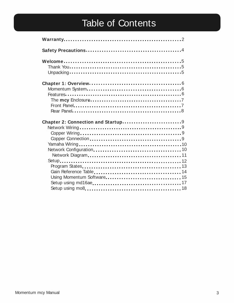
3 Momentum mcy Manual
Warranty
Safety Precautions
Welcome Thank You Unpacking
Chapter 1: Overview Momentum System Features The mcy Enclosure Front Panel Rear Panel Chapter 2: Connection and Startup Network Wiring Copper Wiring Copper Connection Yamaha Wiring Network Confi guration Network Diagram Setup Program States Gain Reference Table Using Momentum Software Setup using md16ae Setup using mo8
2
4
5
6
7
8
9
55
6
Table of Contents
eeeee
1011
1314151718
6
7
9
9910
12

4 Momentum mcy Manual
1. Read these instructions carefully.2. Retain these instructions for future reference.3. Heed all warnings.4. Follow all instructions.5. Do not use any part of this apparatus near water.6. Do not block any ventilation openings.7. Do not install near any heat source.8. Do not defeat the safety purposes of the polarized or grounding type plugs.9. Do not use the Momentum power supply for any purpose other than stated in this manual.10. Only use Pro Co recommended accessories with any Momentum device.
To reduce the risk of fi re or electrical shock, do not expose any part of your Momentum System to rain or moisture.
To reduce the risk of electrical shock, do not remove cover. There are no user serviceable parts inside. Refer servicing to service personnel.
Always follow the basic precautions listed below to avoid the possibility of physical injury to you or others, or damage to the device or other property. These precautions include, but are not limited to, the following:
Use Extreme Caution!Before making adjustments to your Momentum system, be aware that certain actions could possibly damage your hearing and/or the audio system itself. Think through your actions and the possible ramifi cations of your adjustments. Proceed with caution and follow these important Safety Instructions:
Safety Precautions
5 Momentum mcy Manual
Thank you for your recent purchase of the Pro Co Momentum mcy. We hope you fi nd our product to be versatile and fl exible. The entire line of Momentum products was designed with the intention of offering optimal fl exibility for multitude of applications.
Pro Co Sound, a Michigan based business, was founded in 1974. We build audio interface products, in-ear monitor controllers and facility distribution systems. We continue to live by our mission;
“To become our customers’ very best partner, by building a world class organization, through contin-ual, rapid improvement in all that we do, and to share in the successes and failures of our efforts.”
Welcome to the Pro Co Family.
Upon receiving your Momentum System, please check all cartons for damage. If there is damage, notify the shipper and dealer in that order. Before removing any components of your Momentum System from the shipping cartons, be sure that the order is complete as expected. Do this by check-ing each Momentum System component on your packing slip to be sure it matches the number of packing boxes and the specifi c type and number of components contained within. Fill out the war-ranty cards and send them in! You should fi nd one Pro Co Momentum mcy with its accompanying PC software in the carton.
Welcome
Thank You
Receiving Your Momentum mcy

6 Momentum mcy Manual
Your new mcy allows you to connect your Yamaha console to the Momentum network. It allows con-trol over Momentum Input Devices through the Yamaha console.
Chapter 1
Overview 1
Momentum System
Features
The Momentum digital snake system by Pro Co is designed to replace traditional analog audio wiring anywhere audio distribution is needed. By capturing audio at the source, converting it to digital audio and distributing it over a standard Ethernet network, many of the diffi culties in executing the increas-ingly complicated audio systems of today can be simplifi ed. By reducing the amount of fi eld terminations, installation becomes less time consuming. Texas Instruments, Burr Brown mic preamps and Cirrus Logic digital converters provide a platform that is as close to analog as possible without the inherent problems that are associated with traditional wiring.
Flexibility and expandability are enhanced through the use of modules for inputs, outputs and DSPs. Signal routing becomes as easy as clicking a button. You can place inputs, outputs, DSPs and controls anywhere on the Momentum network. Also digital interfaces are available for seamless system integra-tion into many of the popular formats.
100 Mbit Ethernet Connection• Firmware upgradable in the fi eld• Control via free pc software•

7 Momentum mcy Manual
The mcy requires an external 5VDC power supply. The fl anges on the mcy allow you to mount the unit at various locations near the control device.
mcy Rear View mcy Front View
OverviewChapter 1
The mcy Enclosure
Front PanelThe front of the mcy has three LED’s indicating the Momentum network connection, control connection and the mcy status. The USB connection is not currently implemented on the mcy.
Connector/LED Description1 USB Connector Not currently implemented on the mcy.2 Momentum LED RED = Associated device connection error
GREEN = All associated devices are onlineFlashing GREEN = Communication with any Momentum device
3 Control LED RED = Signal lost from the control deviceGREEN = Connection to control device presentFlashing GREEN = Communicating with control device
4 mcy Statusy RED = Associated device setup has not been completedGREEN = Associated device setup has been completedFlashing GREEN = Synchronizing
1 2 3 4

8 Momentum mcy Manual
OverviewChapter 1
Rear PanelOn the back on the mcy is the 100 Mb Ethernet connection, Yamaha RS422 connection, power connection and reset button.
Connector Description1 Ethernet Connection Standard 100Mb Network connection
2 Yamaha RS422 Connection DB-9 connection to Yamaha console3 Reset button Resets settings4 Power Connector 5VDC input supplied
1 2 43

9 Momentum mcy Manual
Chapter 2
Connection and Startup 2
Copper WiringUse a • CAT6 network cableMaximum cable length is 100 meters• Maximum cable length with POE is 50 meters•
Network Wiring
Copper ConnectionUse T568B or equivalent connectors when wiring your system. This view shows the color code as • viewed from the front of the female socket or the rear of the male connector. Crossover wiring is not needed; the Momentum network interface compensates for unit-to-unit • connections.
T568B
Pin T5688 (female) Description1 Orange/White Bi-directional pair +A
2 Orange Bi-directional pair - A3 Green/White Bi-directional pair +B4 Blue/Power Bi-directional pair +C5 Blue/White Bi-directional pair - C
6 Green Receive Bi-directional pair - B
7 Brown/White Bi-directional pair +D
8 Brown Power Bi-directional pair - D

10 Momentum mcy Manual
Connection and Setup Chapter 2
The mcy requires a DB-9 connection between the mcy and the Yamaha console. The Ethernet port that is connected to your mcy must be set to multicast fi ltering. Multicast MAC 01:15:AB:C6:00:00(See page 11 for network setup diagram.)
Network Confi gurations
Yamaha Wiring
Pin Function1 No Connect
2 Tx-3 Rx-4 Rx5 Ground
6 Tx
7 No Connect
8 No Connect
9 Ground
Pin-out for Yamaha Connection

11 Momentum mcy Manual
Connection and SetupChapter 2
Diagram: Connecting the Momentum Network to the Yamaha Console using the mcy
STAGE
FOH
CAT5E or CAT6
Managed Ethernet Switch
Control PC
You MUST set the Ethernet port that is connected to your control PC and mcy to multicast filtering.01:15:AB:C6:00:00(See Network Design White Papers)
!
!
Chn 001 must be present on the network at all times. This unit will sync the network clock.
Chi=081 Cho=001 Adr=007
Chi=O97 Cho=017 Adr=008
Chi=113 Cho=033 Adr=009
Managed Ethernet Switch
md16ae Input/Output
md16ae Input/Output
md16ae Input/Output
Chn=001 Adr=001
Chn=009 Adr=002
mi8 InputChn=017 Adr=003
mi8 InputChn=025 Adr=004
mi8 Input
mi8 Input
mi8 InputChn=033 Adr=005
mi8 InputChn=041 Adr=006
To Slot 1 & 2
To Slot 3 & 4
To Slot 5 & 6
RS-422 Twisted Pair
mcy

12 Momentum mcy Manual
Connection and SetupChapter 2
Setup
Background Information on using the Yahama Console to control the Momentum network through the mcy
Associated Device• An associated device will be either a mo8 or md16ae. These Momentum output units can be connected in two different ways depending on which unit is being used. The md16ae must be connected to the Yamaha MY16-AE card. The mo8 will connect directly into the analog channel input.
When changes are made on the Yamaha console, the mcy will automatically make the appropriate adjustments to the specifi ed Momentum input channels. An md16ae will always occupy two virtual rack spaces in the Yamaha console. If the routing is changed in the output unit, it will be automatically resolved by the mcy within 15 seconds.
Other Momentum Devices• The other Momentum devices are automatically detected by the mcy and no further setup is required. New devices and network topology changes are automatically de- tected by the mcy. There is a maximum of 60 mi8 or md16ae devices allowed on the network with one mcy. There can be an unlimited number of mo8 or mo8me’s on the network.
Error Reporting• If a change is made on the Yamaha console, the mcy will attempt to apply the change to the associated input channel. If the set fails or the output is routed to a channel that does not currently exist on the network, the change will automatically be undone on the Yamaha console to alert the user of the failure.
Master• The Yamaha console becomes the master and takes control over the inputs it is as- sociated with. Hence, if a user attempts to change an input with either another mcy or the PC control software, the changes will automatically revert back to the Yamaha settings.

13 Momentum mcy Manual
If associated devices have been setup the status LED will be green, otherwise it will remain red until setup has been completed with a PC using the Momen- tum Control Software v1.2.0.0 or greater.
Connection and SetupChapter 2
Program States of the mcy
If the associated devices have been setup, the mcy will attempt to establish con- nection with the devices. The mcy will also detect the Momentum devices on the wire. If connection with all of the associated devices is successful the Momentum LED will be green. Otherwise, it will remain red until connection with all associated devices has been made. The mcy will also receive the gain and phantom power settings from the mi8s.
After powering up the mcy, the unit will go through a number of “states.” These states are displayed by the three LEDs on the front of the unit. The following diagrams describe the mcy program states and what they mean.
The mcy will take the Momentum gain and phantom power state and send it to the Yamaha console. If any of the gain settings are out of the range of the console they will be PHYSICALLY changed to the closest gain setting within range. (See reference table on page 14.)
Boot State – Check Setup Status•
Establish Momentum Connection State•
Boot complete. All three LED’s should be green.•

14 Momentum mcy Manual
Connection and SetupChapter 2
Key: Gray = not applicable The lowest gain setting is -1 on the Yamaha console.
Gain Reference Table
Yamaha Gain Momentum GainGain Pad
109876543210
LINELINELINELINELINELINELINELINELINELINELINE
ONONONONONONONONONONON
-1-2-3-4-5-6-7-8-9-10-11-12-13-14-15-16-17-18-19-20-21-22-23-24-25-26-27-28-29-30
LINE1011121314151617181920212223242526272812131415161718192021
ONONONONONONONONONONONONONONONONONONONONOFFOFFOFFOFFOFFOFFOFFOFFOFFOFF
Yamaha Gain Momentum GainGain Pad
-31-32-33-34-35-36-37-38-39-40-41-42-43-44-45-46-47-48-49-50-51-52-53-54-55-56-57-58-59-60-61-62
2223242526272829303132333435363738394041424344454647484950515253
OFFOFFOFFOFFOFFOFFOFFOFFOFFOFFOFFOFFOFFOFFOFFOFFOFFOFFOFFOFFOFFOFFOFFOFFOFFOFFOFFOFFOFFOFFOFFOFF

15 Momentum mcy Manual
Connection and SetupChapter 2
Creating Network Setting with the mcy using Momentum SoftwareThe mcy must be associated with the Momentum output devices that are connected to the slots on the Yamaha console.
Drag and place output channels into the appropriate slot. Please note that the Md16ae and mo8 output units have different setups:
Md16ae Setup (See page 17 for diagram)• In this setup, once the Yamaha channels are routed to the AES-3 slots, the Yamaha channel controls (gain and phantom power) are automatically sent out the DB-9 control port to the mcy. The mcy then sends the changes to the corresponding input.
Mo8 Setup (See page 18 for diagram)• In this setup, the individual Yamaha channel still controls the Yamaha pre-amp (gain and phantom power) because it is still in use. However, control of the mi8s is still possible by navigating through the External Head Amp screen on the Yamaha console. (See page 16 for illustration of the Yamaha External Head Amp screen.) If the mo8 is physically connected channels 1 through 8, then the mcy should be setup with the mo8 in slot 1 using the PC software, if the mo8 is physically connected to channels 9 through 16, then the mcy should be setup with mo8 in slot 2 using the PC software.
Momentum Software

16 Momentum mcy Manual
Connection and SetupChapter 2
The Yamaha External Head Amp (HA) screen

17 Momentum mcy Manual
Connection and SetupChapter 2
You MUST set the Ethernet port that is connected to your control PC and mcy to multicast filtering.01:15:AB:C6:00:00(See Network Design White Papers)
!
!
Chn 001 must be present on the network at all times. This unit will sync the network clock.
Chi=017 Cho=001 Adr=002md16ae Input/Output
Chn=001 Adr=001mi8 Input
To Slot 1
RS-422 Twisted Pair
IMPORTANT: Note Input Control Differs whether using the mcy with the md16ae or mo8When using the Yamaha console with the md16ae, the input controls on the channel are now directly controlling the Momentum devices.
Yamaha Console receiving inputs from the md16ae

18 Momentum mcy Manual
Connection and SetupChapter 2
You MUST set the Ethernet port that is connected to your control PC and mcy to multicast filtering.01:15:AB:C6:00:00(See Network Design White Papers)
!
!
Chn 001 must be present on the network at all times. This unit will sync the network clock.
Chn=001 Adr=002mo8 Output
Chn=001 Adr=001mi8 Input
RS-422 Twisted Pair
To Analog Input #1
IMPORTANT: Note Input Control Differs whether using the mcy with the md16ae or mo8When using the Yamaha console with mo8s, the input controls are only accessible from the “External HA (Head Amp)” screen. The input controls on the channel still control the Yamaha input.
Yamaha Console receiving inputs from the mo8

Pro Co Sound, Inc.225 Parsons Street | Kalamazoo, MI 49007
1-888-253-7360 | www.procomomentum.com