
DOOR ENTR Y SYSTEMS - Alcad.net · 2 CONTENTS 1. DOOR ENTRY SYSTEM • Description • Components...
75
201 L I N E TECHNICAL MANUAL Tel. 943.63.96.60 Fax 943.63.92.66 Int. Tel. +34 943.63.96.60 [email protected] Polígono Arreche-Ugalde, Nº 1 Apdo. 455 E-20305 IRUN - Spain www.alcad.net TECHNICAL MANUAL 201 LINE D O O R E N T R Y S Y S T E M S
Transcript of DOOR ENTR Y SYSTEMS - Alcad.net · 2 CONTENTS 1. DOOR ENTRY SYSTEM • Description • Components...

201L I N E
T E C H N I C A L M A N U A L
Tel. 943.63.96.60Fax 943.63.92.66
Int. Tel. +34 943.63.96.60 [email protected]
Polígono Arreche-Ugalde, Nº 1 Apdo. 455
E-20305 IRUN - Spain
www.alcad.net
TE
CH
NI
CA
L
MA
NU
AL
20
1
LI
NE
D O O R E N T R Y S Y S T E M S

2
CONTENTS1. DOOR ENTRY SYSTEM
• Description• Components
2. TECHNICAL DATA• Standards• Telephones• Audio units• Power supplies• Entrance panels
- Entrance panel modules with audio unit- Entrance panel module with card holder- Blank entrance panel module- Entrance panel modules with single row push buttons- Entrance panel modules with double row push buttons
• Kits• Accessories
- Electrick locks- Door contact
• Panel accessories- Ready assembled flush-mounted boxes- Flush-mounted box separator
3. RANGE OF ENTRANCE PANELS• Entrance panels• Kit entrance panels• Dimensions of entrance panels
4. ASSEMBLY• Flush-mounted box
- Removing the punched knockouts- Assembling several boxes- Height of placement
• Entrance panel- Assembling entrance panels- Complete disassembly of entrance panels- Fitting the panel to the flush-mounted box
• Audio unit- Fitting the audio unit- Removing the audio unit
• Push buttons- Fitting push buttons- Removing push buttons- Placing identifying labels
• Telephone- Removing the base cover- Fixing the base to the wall- Fitting the base cover- Fitting the handset
• Power supply- Wall mounting- Fitting to a DIN rail- Removing from DIN rail- Fixing the terminal cover
45
668
1011111111121213141415151515
162022
24242424252525252727272727272828282929293030303030
Page

3
5. CONNECTION AND SET-UP INSTRUCTIONS• Audio unit
- Electronic audio unit GRF-001- Terminal connections- Audio unit set-up
- Mixed audio unit GRF-005- Terminal connections- Audio unit set-up
- Audio unit multi entrance without privacy of conversation GRF-003. Audio unit with privacy of conversation GRF-004- Terminal connections- Audio unit set-up
• Telephone- Electronic telephone TEL-001. Electronic telephone with privacy of conversation TES-001
- Terminal connections- Universal telephone TUN-001
- Terminal connections- Telephone set-up
• Power supply- Terminal connections
6. CIRCUIT DIAGRAMS• General points concerning tthe installation• 4+N system circuit diagrams
- Basic installation with electronic call - Basic installation with buzzer call- Expansion of the installation with additional telephones- Opening the door from inside the building
• Microprocessor-based 4+N system circuit diagrams- Basic installation with electronic call- Basic installation with electronic call and privacy of conversation- Two entrance installation with electronic call- Three entrance installation with electronic call- Installation with electronic call in a complex with several blocks - Two entrance installation with electronic call and privacy of conversation - Three entrance installation with electronic call and privacy of conversation - Installation with electronic call and privacy of conversation
in a complex with several blocks- Expansion of the system with additional telephones- Expansion of the system with additional telephones in installations with privacy of conversation
- Opening the door from inside the building
7. TROUBLESHOOTING• Basic installations. 4+N System• Installations with several entrances or complexes with several blocks.
Microprocessor-based 4+N System• Installations with privacy of conversation: Basic installations with several entrances
or complexes with several blocks. Microprocessor-based 4+N system
313131313232323333333434343434343535
373838404243444546485154576063
6667
68
6971
73
Page

TELEPHONE ATTHE DWELLING
PUSH BUTTON
ELECTRIC LOCK
POWER SUPPLY
230 V230 V VENTRANCE PANEL
4
The door entry system is a security measure inwidespread use in dwellings today where it cons-titutes a straightforward means controlling physi-cal access to the property from the outside.
A large number of installation configurations arepossible; from basic ones with a single entrance,to more complex installations, such as buildingswith multiple entrances or residential complexeswith a general entrance and one or more buil-dings.
The system consists normally of an entrancepanel –normally fitted at the entrance to the buil-ding– connected to a telephone in each area ordwelling.
The entrance panel incorporates a series ofpush buttons. Each push button corresponds toan individual dwelling, so the number of pushbuttons on the entrance panel depends on thenumber of dwellings. When a push button on theentrance panel is pressed it calls the appropiatetelephone. When the telephone handset is picke-dup, communication is established with the call-panel. The user can then open the door remotelyif desired by pressing the lock release button onthe telephone.
Like any other electronic system, the door entrysystem requires an external source of power inorder to work. This function is performed by thepower supply unit which converts mains electri-city into the voltages required by the system. Thepower supply is usually sited in the hallway or acommon area of the building and normally nearthe entrance panel for optimum operation.
It is possible to install individual entrancepanels in the case of buildings with multipleentrances or in residential complexes with ageneral entrance and one or more buildings.
A common system in use for door entry systemis referred to as the 4+ N, which is characterizedby the fact that the telephone in each dwelling isconnected by five wires. Four of these wires are
common to all the telephones in the building,whereas the fifth wire is used to call each indivi-dual dwelling. A system configured in this waywill require 4+N wires, where N is the numberof dwellings in the building or complex.
DESCRIPTION
DOOR ENTRY SYSTEM1

5
TELEPHONESFitted in each dwelling, they ena-
ble the user to answer the call fromthe entrance panel, talk to the callerand open the door.
ENTRANCE PANELGenerally installed at the entrance
to the building, this houses the audiounit and the push buttons, all ofwhich are essential parts of the doorentry system, allowing bi-directionalcommunication between the dwe-lling unit and the entrance panel.
The panel’s dimensions dependon the number of floors the buildingin which the system is being insta-lled comprises.
More than one entrance panelmay be necessary, depending onthe number of dwellings and on thetype of system.
AUDIO UNITThis is the core of the door entry
system. Its electronics allow bi-direc-tional communication between theentrance panel and the dwellingunit. It is housed in the entrance panel.
PUSH BUTTONSThe elements in the entrance panel
allowing each of the dwellings to becontacted. The number of push but-tons will be determined by the num-ber of dwellings.
ELECTRICK LOCKThis is an electrical device which
allows the door to be opened. Itrequires electrical power in order towork.
POWER SUPPLYThe part of the system which con-
verts mains electricity into the volta-ges the door entry system needs towork properly.
COMPONENTS
230 V230 V V

6
Every door entry system product listed here complies with the European Union safety standard EN60065- Audio, video and similar electronic apparatus - Safety requirements; as well as with the European Uniondirective as regards electromagnetic compatibility, according to the standards EN50081-1 -Electromagnetic compatibility - Generic emissions standard, EN50082-1 - Electromagnetic compatibility- Immunity.The ALCAD door entry system products are, therefore, marked with the CE Marking.
TECHNICAL DATA2
STANDARDS
TELEPHONES
Loudspeaker
Microphone
Common line
Door lock release
TERMINALS REST WORKING
Electronic call
Ground
Max audio 4 Vpp
Max audio 7.0 Vpp
Max tone 7 Vpp
Description of terminals and
voltages:
Door lock release
Common line
Microphone
Loudspeaker
Electronic call
Ground
REST WORKING
5 V
8 V
0 V
0 V
Max Audio 4 Vpp
Max audio 7.0 Vpp
IDLE
5 V
0 V
0 V
0 V9 V
Max Tone 7 Vpp
1
2
3
4
5
0 V
5.6 - 6.6 V
TERMINALS
Description of terminals and
voltages:
Ref. 9600001ELECTRONIC TELEPHONE
TEL-001
Telephone intended for wall mounting in conventio-nal 4+N system. The telephone unit comprises a base,a handset and a handset cord. This allows the user toanswer the call from the entrance panel, talk to thecaller and operate the electric door lock by pressing abutton. The door lock release button is located on theside of the telephone, so it can be used without pickingthe handset up. The call is electronic and can be dualor tri-tone. This call tone is generated by the entrancepanel audio unit and heard over the loudspeaker inthe telephone handset.
Dimensions of base + handset: 84 mm x 224 mmx 50.6 mm
Operating temperature +5 to +55°C
Ref. 9600003ELECTRONIC TELEPHONE WITH PRIVACYOF CONVERSATION
TES-001
Telephone intended for wall mounting in conventional4+N system. Has the same characteristics as electronictelephone TEL-001 (Ref. 9600001), except that thismodel includes a speech privacy. The audio system isdisabled in all the handsets except in the one, which iscalled. In this way the user at the called dwelling end canhold a private conversation with the entrance panelwhile the rest of the telephones are disabled.
For use in installations with an audio unit with privacyof conversation GRF-004 (Ref. 9610005)
Dimensions of base + handset: 84 mm x 224 mmx 50.6 mm
Operating temperature +5 to +55°C

7
Microphone
Door lock release
Loudspeaker
Electronic call
Ground
TERMINALS REST WORKING
Common line
Buzzer call
Max Audio 4 Vpp
Max audio 7.0 Vpp
Max Tone 7 Vpp
Description of terminals and
voltages:
Ref. 9600002UNIVERSAL TELEPHONE
TUN-001
Telephone intended for wall mounting in conven-tional 4+N system. Compatible with door entrysystems produced by a broad range of manufactu-rers. Can be used in systems with either an electro-nic call or buzzer.
The telephone unit comprises a base, a handsetand a handset cord. This allows the user to answerthe call from the entrance panel, talk to the callerand operate the electric door by pressing a button.The door lock release button is located on the side ofthe telephone, so it can be used without picking thehandset up.
It has audio level controls ensuring the telephoneworks perfectly with any entry door entry system.This enables possible feedback problems at theentrance panel or telephone end to be avoided.
A jumper is incorporated to enable compatibilitywith 4+N separated common lines door entrysystems.
Dimensions of base + handset: 84 mm x 224 mmx 50.6 mm
Operating temperature +5 to +55°C

8
AUDIO UNITS
REST WORKINGTERMINALS
Power ground
Power voltage
Door lock release
Telephone common terminal
Telephone microphone
Telephone loudspeaker
Push button common terminalelectronic call
Panel lighting
Panel lighting
Electric lock
Electric lock
Ground
Ground
Max Audio 4 Vpp
Max audio 7.0 Vpp
Max Tone 7 Vpp
Ground
Ground
79 10 11 1212 V~
V~ 1 2 3 4
Description of terminals and
voltages:
Audio units are included in the upper module of the entrance panel (MAN models) and it is not ne-cessary to order a unit separately with these models.
Ref. 9610001ELECTRONIC AUDIO UNIT
GRF-001
Conventional 4+N system. Audio unit forbasic installations.
Consists of loudspeaker, microphone,amplifier, panel and telephone volume con-trols, lock release relay, and lighting pushbutton for the entrance panel.
Has a dual-tone or tri-tone electronic call withcall confirmation at the entrance panel end.
Short-circuit protected.Operating temperature -10 to +55°C
Max Tone 7 Vpp
Power ground
Power voltage
Door lock release
Telephone common terminal
Telephone microphone
Telephone loudspeaker
Push button common terminalelectronic call
Panel lighting
Panel lighting
Electric lock
Electric lock
Push button common terminalbuzzer call
REST WORKINGTERMINALS
Ground
Ground
Max Audio 4 Vpp
Max audio 7.0 Vpp
Ground
Ground
Description of terminals and
voltages:
Ref. 9610002MIXED AUDIO UNIT
GRF-005
Conventional 4+N system. Audio unit forbasic installations.
Consists of loudspeaker, microphone,amplifier, panel and telephone volume con-trols , lock release relay, and lighting pushbutton for the entrance panel.
Electronic dual-tone or tri-tone call or bu-zzer. Includes calls confirmation at the entran-ce panel end.
Short-circuit protected.Operating temperature -10 to +55°C

9
Description of terminals and
voltages:
Ref. 9610004AUDIO UNIT MULTI ENTRANCE WITHOUTPRIVACY OF CONVERSATION
GRF-003
Conventional 4+N system. Audio unit for insta-llations in buildings with multiple entrances or resi-dential complexes with one or more general entran-ces.
Consists of a microprocessor, loudspeaker,microphone, amplifier, panel and telephone vo-lume controls, lock release relay, lighting push bu-tton for the entrance panel and a red indicator lightwhen the system is busy. The call is electronic.Includes call confirmation at entrance panel end.
Short-circuit protected.The audio unit controls the panel s relative prio-
rities. Does not require additional components suchas switches or automatic changeover devices tohandle installations of this type.
The use of this type of audio unit in installationsof the type described makes the task of connectingup the system much more straightforward for theinstaller.
Operating temperature -10 to +55°C
Description of terminals and
voltages:
Ref. 9610005AUDIO UNIT WITH PRIVACY OF CONVERSATION
GRF-004
Conventional 4+N system. Audio unit for insta-llations requiring speech privacy. Valid for installa-tions with single or multiple entrance.
Consists of a microprocessor, loudspeaker,microphone, amplifier, volume control at theentrance panel and telephone ends, lock releaserelay, light button for the entrance panel and a redindicator light when the system is busy - in the caseof systems with more than one entrance. The callis electronic. Includes call confirmation at entrancepanel end.
Short-circuit protected.For systems with multiple entrances, the audio
unit controls the panel´s relative priorities. It doesnot require additional components such as swit-ches or automatic changeover devices.
The use of this type of audio unit in installationsof the type described makes the task of connectingup the system much more straightforward for theinstaller.
For use in installations with electronic telephoneswith privacy of conversation TES-001 (Ref. 9600003)
Operating temperature -10 to +55°C
Telephone common terminal
9 10 11 12 13 14 1512 V~
V~ 1 2 3 4 7 16 17 18
Max Tone 7 Vpp
Power ground
Power voltage
Door lock release
Telephone microphone
Telephone loudspeaker
Push button common terminal(electronic call)
Panel lighting
Panel lighting
Electric lock
Electric lock
Max Audio 4 Vpp
Max audio 7.0 Vpp
Ground
Complete multiple access
Multiple access
Multiple access common terminal
Ground
Ground
Ground
Ground
REST WORKINGTERMINALS
9 10 11 12 13 14 1512 V~
V~ 1 2 3 4 7 16 17 18
10
Telephone common terminal
Max Tone7 Vpp
Power ground
Power voltage
Door lock release
Telephone microphone
Telephone loudspeaker
Push button common terminal(electronic call)
Panel lighting
Panel lighting
Electric lock
Electric lock
Max Audio 4 VppMax tone 7.0 Vpp
Ground
Complete multiple access
Multiple access
Multiple access common terminal
REST WORKINGTERMINALS
Ground
Ground
Ground
Ground
IDLE

Description of terminals and technical characteristics:
POWER SUPPLIES
10
Mains voltage
TERMINALS
Ground
Output voltage
Output power
Ground
CHARACTERISTICS
Ref. 9620002POWER SUPPLY KIT
ALA-020
Power supply for small installations serving upto 12 dwellings. This model of power supply isprovided with the kits.
6 component DIN rail format. Wall or railmounting.
Short-circuit protected. Dimensions: 106 mm x 90 mm x 60 mm Operating temperature -10 to +55°C
Description of terminals and technical characteristics:
Mains voltage
TERMINALS
Ground
Output voltage
Output power
Ground
CHARACTERISTICS230 V230 V V
230 V230 V V
Ref. 9620001POWER SUPPLY
ALA-040
Large capacity power supply, for installationsserving more than 12 dwellings.
6 component DIN rail format. Wall or railmounting.
Short-circuit protected. A single power supply is required for basic ins-
tallations. In complex installations we recommendyou to use a separate power supply for eachentrance panel with audio unit.
Dimensions: 106 mm x 90 mm x 60 mm Operating temperature -10 to +55°C

11
ENTRANCE PANELS
ENTRANCE PANEL MODULES WITH AUDIO UNIT
Upper part of the entrance panel. Available in fourmodels, one for each of the possible audio units (Seethe characteristics of the different audio units in thesection “Audio units” on page 8).
Ref. 9670001 MAN-010Entrance panel module with elec-tronic 4+N audio unit GRF-001(Ref. 9610001)
Ref. 9670002 MAN-050Entrance panel module with mixed4+N audio unit GRF-005 (Ref.9610002)
Ref. 9670004 MAN-030
Ref. 9670005 MAN-040Entrance panel module with 4+Naudio unit with privacy of conversa-tion GRF-004 (Ref. 9610005)
1
Entrance panel module with 4+Naudio unit multi entrance without pri-vacy of conversation GRF-003 (Ref.9610004)
ENTRANCE PANEL MODULE WITH CARD HOLDER
Upper part of the entrance panel. Normally for ins-tallations with several entrance panels, where youwant to put information of interest at one of the entran-ce panels.
Ref. 9670018 MTN-000Entrance panel module with cardholder
BLANK ENTRANCE PANEL MODULE
Upper part of the entrance panel. Makes it possibleto give a good aesthetic appearance to the installa-tion. For use in the case of entrance panels withoutaudio unit.
Ref. 9670021 MLN-000Blank entrance panel module
The entrance panel system consists of two modules, each of which is available in va-rious models. These modules make us the upper and lower part of the entrance panel tobe installed. Any entrance panel configuration may be obtained by assembling thesetwo modules.
These models offer ease of assembly for the installer and a pleasing aesthetic appea-rance.

12
ENTRANCE PANEL MODULES WITH SINGLE ROW PUSH BUTTONSLower part of the entrance panel. Module housing the push buttons used to call the various
dwellings. Available for 3 to 16 storeys configurations with 1 dwelling per storey.
Ref. 9660000 MPS-003Entrance panel module with 3 push buttons insingle row
Ref. 9660001Entrance panel module with 4 push buttons insingle rowRef. 9660002 MPS-005Entrance panel module with 5 push buttons insingle rowRef. 9660003 MPS-006Entrance panel module with 6 push buttons insingle rowRef. 9660004 MPS-007Entrance panel module with 7 push buttons insingle rowRef. 9660005 MPS-008Entrance panel module with 8 push buttons insingle row
Ref. 9660006 MPS-009Entrance panel module with 9 push buttons insingle row
Ref. 9660007 MPS-010Entrance panel module with 10 push buttons insingle row
Ref. 9660008 MPS-011Entrance panel module with 11 push buttons insingle rowRef. 9660009 MPS-012Entrance panel module with 12 push buttons insingle rowRef. 9660010 MPS-013Entrance panel module with 13 push buttons insingle rowRef. 9660011 MPS-014Entrance panel module with 14 push buttons insingle rowRef. 9660012 MPS-015Entrance panel module with 15 push buttons insingle row
Ref. 9660013 MPS-016Entrance panel module with 16 push buttons insingle row
ENTRANCE PANEL MODULES WITH DOUBLE ROW PUSH BUTTONSLower part of the entrance panel. Module housing the push buttons used to call the various
dwellings. Available for 3 to 16 storeys configurations with 2 dwellings per storey.
Ref. 9660050 MPD-003Entrance panel module with double row push buttons, 3 push buttons per rowRef. 9660051 MPD-004Entrance panel module with double row push buttons, 4 push buttons per rowRef. 9660052 MPD-005Entrance panel module with double row push buttons, 5 push buttons per rowRef. 9660053 MPD-006Entrance panel module with double row push buttons, 6 push buttons per rowRef. 9660054 MPD-007Entrance panel module with double row push buttons, 7 push buttons per rowRef. 9660055 MPD-008Entrance panel module with double row push buttons, 8 push buttons per rowRef. 9660056 MPD-009Entrance panel module with double row push buttons, 9 push buttons per row
Ref. 9660057 MPD-010Entrance panel module with double row pushbuttons, 10 push buttons per rowRef. 9660058 MPD-011Entrance panel module with double row pushbuttons, 11 push buttons per rowRef. 9660059 MPD-012Entrance panel module with double row pushbuttons, 12 push buttons per rowRef. 9660060 MPD-013Entrance panel module with double row pushbuttons, 13 push buttons per rowRef. 9660061 MPD-014Entrance panel module with double row pushbuttons, 14 push buttons per rowRef. 9660062 MPD-015Entrance panel module with double row pushbuttons, 15 push buttons per rowRef. 9660063 MPD-016Entrance panel module with double row pushbuttons, 16 push buttons per row
MPS-004

13
KITS
The most convenient solution for installations serving anything from an individualhouse to a block of up to 12 dwellings.
Each kit is supplied with the following elements:• Electronic telephones TEL-001 (Ref. 9600001) - same number of
telephones as the number of push buttons on the entrance panel.• Entrance panel with electronic 4+N audio unit GRF-001 (Ref. 9610001)
and number of call buttons depending on the number of dwellings.• Flush-mounted box of the correct size for the entrance panel.• Power supply kit ALA-020 (Ref. 9620002).• Standard electric lock ABR-001 (Ref. 9730000).[Not included in all the kits]
Nine kits with electric lock included are available, varying according to thecharacteristics of the installation to be fitted:
Two kits without electric lock are available varying according to the characteris-tics of the installation to be fitted.
Ref. 9700000 KAS-01001Kit comprising 1 push button panelin single row 4+N systemRef. 9700001 KAS-01003Kit comprising 3 push buttons panel insingle row 4+N system
Ref. 9700018 KAS-01201Kit without electric lock, comprising 1 pushbutton panel in single row 4+N system
Ref. 9700021 KAS-01201Kit without electric lock, comprising doublerow push button panel, 1 push button per row
Ref. 9700002 KAS-01005Kit comprising 5 push buttons panel insingle row 4+N system
Ref. 9700003 KAD-01001Kit comprising double row push buttonpanel, 1 push button per row 4+N system
Ref. 9700004 KAD-01002Kit comprising double row push buttonspanel, 2 push buttons per row 4+N system
Ref. 9700005 KAD-01003Kit comprising double row push buttonspanel, 3 push button per row 4+N systemRef. 9700006 KAD-01004Kit comprising double row push buttonspanel, 4 push button per row 4+N system
Ref. 9700007 KAD-01005Kit comprising double row push buttonspanel, 5 push buttons per row 4+N system
Ref. 9700008 KAD-01006Kit comprising double row push buttonspanel, 6 push buttons per row 4+N system
Power supply
Electric telephone
Entrance panel(size depending
on the adquired kit)
Flush-mounted box(size depending
on the adquired kit)
Electric lock(not includedin all the kits)
230 V230 V V
14
ACCESSORIES
31 mm
100
mm
30 m
m
3 mm
160
mm
25 mm
31 mm
100
mm
30 m
m
3 mm
160
mm
25 mm
31 mm
100
mm
30 m
m
3 mm
160
mm
25 mm
31 mm
100
mm
30 m
m
3 mm
160
mm
25 mm
ELECTRIC LOCKS
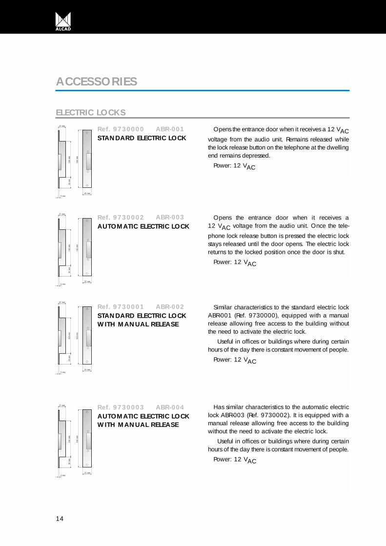
Ref. 9730000STANDARD ELECTRIC LOCK
ABR-001 Opens the entrance door when it receives a 12 VACvoltage from the audio unit. Remains released whilethe lock release button on the telephone at the dwellingend remains depressed.
Power: 12 VAC
Ref. 9730002AUTOMATIC ELECTRIC LOCK
ABR-003 Opens the entrance door when it receives a 12 VAC voltage from the audio unit. Once the tele-
phone lock release button is pressed the electric lockstays released until the door opens. The electric lockreturns to the locked position once the door is shut.
Power: 12 VAC
Ref. 9730001STANDARD ELECTRIC LOCK WITH MANUAL RELEASE
ABR-002 Similar characteristics to the standard electric lockABR-001 (Ref. 9730000), equipped with a manualrelease allowing free access to the building withoutthe need to activate the electric lock.
Useful in offices or buildings where during certainhours of the day there is constant movement of people.
Power: 12 VAC
Ref. 9730003AUTOMATIC ELECTRIC LOCKWITH MANUAL RELEASE
ABR-004 Has similar characteristics to the automatic electriclock ABR-003 (Ref. 9730002). It is equipped with amanual release allowing free access to the buildingwithout the need to activate the electric lock.
Useful in offices or buildings where during certainhours of the day there is constant movement of people.
Power: 12 VAC

15
DOOR CONTACT
Ref. 9730004DOOR CONTACT
CNP-001
Accessory which, when used in conjunctionwith an electric lock, allows double doors tobe opened.
Door contact - Male Door contact - Female
PANEL ACCESSORIESIt´s necessary to use a flush-mounted box to install the entrace panel in the required place.
Ref. 9740005 CMO-002Ready-assembled flush-mounted boxfor 1 or 2 storeys entrance panel
Ref. 9740006 CMO-004Ready-assembled flush-mounted boxfor 3 or 4 storeys entrance panel
Ref. 9740007 CMO-006Ready-assembled flush-mounted boxfor 5 or 6 storeys entrance panel
Ref. 9740008 CMO-008Ready-assembled flush-mounted boxfor 7 or 8 storeys entrance panel
Ref. 9740009 CMO-010Ready-assembled flush-mounted boxfor 9 or 10 storeys entrance panel
Ref. 9740009 CMO-010Ready-assembled flush-mounted boxfor 9 or 10 storeys entrance panel
Ref. 9740010 CMO-012Ready-assembled flush-mounted boxfor 11 or 12 storeys entrance panel
Ref. 9740011 CMO-014Ready-assembled flush-mounted boxfor 13 or 14 storeys entrance panel
Ref. 9740012 CMO-016Ready-assembled flush-mounted boxfor 15 or 16 storeys entrance panel
READY-ASSEMBLED FLUSH-MOUNTED BOXES
Available for installations in buildings with 1 to 16 storeys. All flush-mounted boxes have a depth of 45 mm.
(See dimensions for the flush-moun-ted boxes in the “Range of entrancepanels” section, page 16)
FLUSH-MOUNTED BOX SEPARATOR
Ref. 9740004FLUSH-MOUNTED BOX SET OF SEPARATORS
CEM-001
For combinations with more than one entrance panel, box separators will need to be fitted to theflush-mounted boxes to ensure correct separation between the entrance panels. Separators are sup-plied in pairs. Remember that you will need a set of separators for each additional panel.
Note: The descriptionshow above are validwhen the entrance panelupper module is a singleone. For entrance panelswith double upper modu-le (Module with avoidunit and card holder,module with audio andvideo unit, etc.). The boxto be ordered is the follo-wing model.
4 STOREYS AND4 DWELLINGS BUILDING
Entrance panel with singleupper module
Entrance panel with doubleupper module
CMO-006MPD-004CMO-004MPD-004

16
ENTRANCE PANELSBy means of an appropriate combination of entrance panels it is possible to obtain any type of installation
configuration: one or more entrance panels, for one or more entrances. The height of the final panel will depend on both the push button panel selected and the upper module selec-
ted. However, the width will remain constant.
RANGE OF ENTRANCE PANELS3
128 mm
243
mm
5-6
store
ys
MAN-0 1 0MPS-006
MAN-0 1 0MPS-005
MAN-0 1 0MPD-006
MAN-0 1 0MPD-005
MTN-000MPS-006
MTN-000MPS-005
MM
128 mm
291
mm
7-8
store
ys
MAN-0 1 0MPS-008
MAN-0 1 0MPS-007
MAN-0 1 0MPD-008
MAN-0 1 0MPD-007
MTN-000MPS-008
MTN-000MPS-007
MM
128 mm
339
mm
9-10
sto
reys
MAN-0 1 0MPS-010
MAN-0 1 0MPS-009
MAN-0 1 0MPD-010
MAN-0 1 0MPD-009
MTN-000MPS-010
MTN-000MPS-009
MM
Panels with audio unit Panels with car
3-4
store
ys
MAN-0 1 0MPS-004
MAN-0 1 0MPS-003
MAN-0 1 0MPD-004
MAN-0 1 0MPD-003
MTN-000MPS-004
MTN-000MPS-003
MM128 mm
195
mm
Replace this number corresponding to the audio unit you want be installed, as follow: Electric audio unit, GRF-001 (Cód. 9610001) Audio unit multi entrance without privacy of conversation, GRF-003 (Cód. 9610004) Audio unit with privacy of conversation, GRF-004 (Cód. 9610005) Grupo fónico mixto, GRF-005 (Cód. 9610002)
1
5
3
4
1

17
The table shows different possible combinations with simple uppermodules, indicating the models usedfor each panel.
MTN-000MPD-006
MTN-000MPD-005
MLN-000MPS-006
MLN-000MPS-005
MLN-000MPD-006
MLN-000MPD-005
CMO-006
MTN-000MPD-008
MTN-000MPD-007
MLN-000MPS-008
MLN-000MPS-007
MLN-000MPD-008
MLN-000MPD-007
CMO-008
MTN-000MPD-010
MTN-000MPD-009
MLN-000MPS-010
MLN-000MPS-009
MLN-000MPD-010
MLN-000MPD-009
CMO-010
card holder Blank panels Flush-mounted boxes
MTN-000MPD-004
MTN-000MPD-003
MLN-000MPS-004
MLN-000MPS-003
MLN-000MPD-004
MLN-000MPD-003
CMO-004114 mm17
9 m
m
114 mm
227
mm
275
mm
114 mm
114 mm
323
mm
Note: To see configurations with double upper modules or several entrance panels refer to the section“Dimensions of entrance panel” on page 22.

18
Panels with audio unit Panels with car
128 mm
483
mm
15-1
6 sto
reys
MAN-0 1 0MPS-016
MAN-0 1 0MPS-015
MAN-0 1 0MPD-016
MAN-0 1 0MPD-015
MTN-000MPS-016
MTN-000MPS-015
MM
128 mm
435
mm
13-1
4 sto
reys
MAN-0 1 0MPS-014
MAN-0 1 0MPS-013
MAN-0 1 0MPD-014
MAN-0 1 0MPD-013
MTN-000MPS-014
MTN-000MPS-013
MM
128 mm
387
mm
11-1
2 sto
reys
MAN-0 1 0MPS-012
MAN-0 1 0MPS-011
MAN-0 1 0MPD-012
MAN-0 1 0MPD-011
MTN-000MPS-012
MTN-000MPS-011
MM
Replace this number corresponding to the audio unit you want be installed, as follow: Electric audio unit, GRF-001 (Cód. 9610001) Audio unit multi entrance without privacy of conversation, GRF-003 (Cód. 9610004) Audio unit with privacy of conversation, GRF-004 (Cód. 9610005) Grupo fónico mixto, GRF-005 (Cód. 9610002)
1
5
3
4
1

19
card holder Blank panels Flush-mounted boxes
MTN-000MPD-016
MTN-000MPD-015
MLN-000MPS-016
MLN-000MPS-015
MLN-000MPD-016
MLN-000MPD-015
CMO-016
MTN-000MPD-014
MTN-000MPD-013
MLN-000MPS-014
MLN-000MPS-013
MLN-000MPD-014
MLN-000MPD-013
CMO-014
MTN-000MPD-012
MTN-000MPD-011
MLN-000MPS-012
MLN-000MPS-011
MLN-000MPD-012
MLN-000MPD-011
CMO-012114 mm
371
mm
114 mm
419
mm
114 mm
467
mm
20
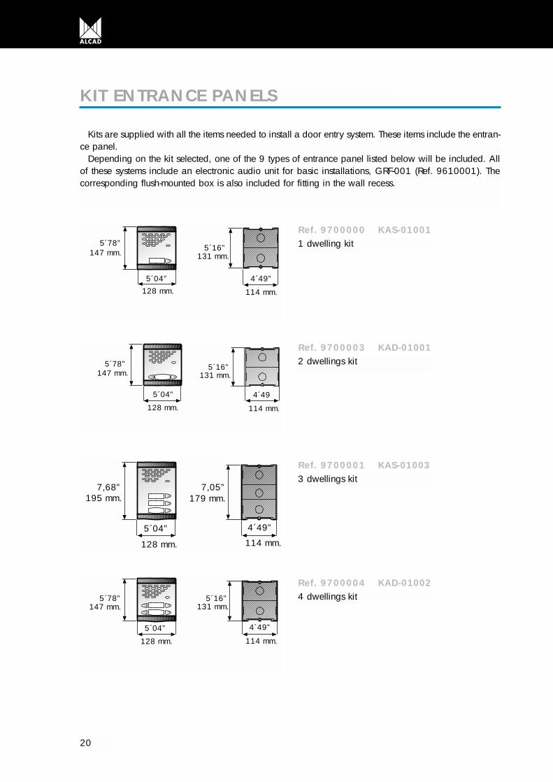
Kits are supplied with all the items needed to install a door entry system. These items include the entran-ce panel.
Depending on the kit selected, one of the 9 types of entrance panel listed below will be included. Allof these systems include an electronic audio unit for basic installations, GRF-001 (Ref. 9610001). Thecorresponding flush-mounted box is also included for fitting in the wall recess.
KIT ENTRANCE PANELS
Ref. 9700000 KAS-010011 dwelling kit
Ref. 9700003 KAD-010012 dwellings kit
Ref. 9700001 KAS-010033 dwellings kit
Ref. 9700004 KAD-010024 dwellings kit
5´78”
5´04”
5´16”
4´49”
147 mm.
128 mm.
131 mm.
114 mm.
5´04”
5´78”
4´49
5´16”147 mm.
128 mm.
131 mm.
114 mm.
7,68”
5´04”
7,05”
4´49”
195 mm.
128 mm.
179 mm.
114 mm.
5´16”5´78”
5´04” 4´49”
147 mm.
128 mm.
131 mm.
114 mm.

21
Ref. 9700002 KAS-010055 dwellings kit
Ref. 9700005 KAD-010036 dwellings kit
Ref. 9700006 KAD-010048 dwellings kit
Ref. 9700007 KAD-0100510 dwellings kit
Ref. 9700008 KAD-0100612 dwellings kit
9´57”
5´04”
8´94”
4´49”
243 mm.
128 mm.
227 mm.
114 mm.
7´68”
5´04”
7´05”
4´49”
195 mm.
128 mm.
179 mm.
114 mm.
7´68”
5´04”
7´05”
4´49”
195 mm.
128 mm.
179 mm.
114 mm.
9´57”
5´04”
8´94”
4´49”
243 mm.
128 mm.
227 mm.
114 mm.
9´57”
5´04”
8´94”
4´49”
243 mm.
128 mm.
227 mm.
114 mm.

DIMENSIONS OF ENTRANCE PANELS
22
Configurations with two panelsFlush mo
Configurations with one panel
179
mm
227
mm
275
mm
256 mm
195
mm
243 mm
179
mm
256 mm
243
mm
243 mm
227
mm
256 mm
291
mm
243 mm
275
mm
256 mm
339
mm
243 mm
323
mm
256 mm
387
mm
371
mm
256 mm
435
mm
419
mm
256 mm
483
mm
467
mm
3-4
heig
hts
5-6
heig
hts
7-8
heig
hts
9-10
hei
ghts
11-1
2 he
ight
s13
-14
heig
hts
15-1
6 he
ight
s
3-4
heig
hts
5-6
heig
hts
7-8
heig
hts
9-10
hei
ghts
11-1
2 he
ight
s13
-14
heig
hts
15-1
6 he
ight
s
128 mm
483
mm
467
mm
128 mm
435
mm
419
mm
128 mm
387
mm
371
mm
128 mm
339
mm
323
mm
128 mm
291
mm
128 mm
243
mm
128 mm
195
mm
114 mm
114 mm
114 mm
114 mm
114 mm
114 mm
114 mm
243 mm
243 mm
243 mm
Flush mounted boxes
23
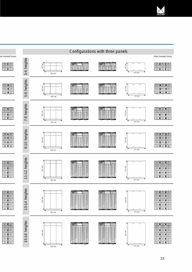
Configurations with three panelsFlush mounted boxesush mounted boxes
3-4
heig
hts
5-6
heig
hts
7-8
heig
hts
9-10
hei
ghts
11-1
2 he
ight
s13
-14
heig
hts
15-1
6 he
ight
s
384 mm
483
mm
384 mm
435
mm
384 mm
387
mm
384 mm
339
mm
384 mm
291
mm
384 mm
243
mm
384 mm
195
mm
372 mm
467
mm
372 mm
419
mm
372 mm
371
mm
372 mm
323
mm
372 mm
275
mm
372 mm
227
mm
372 mm
179
mm
24
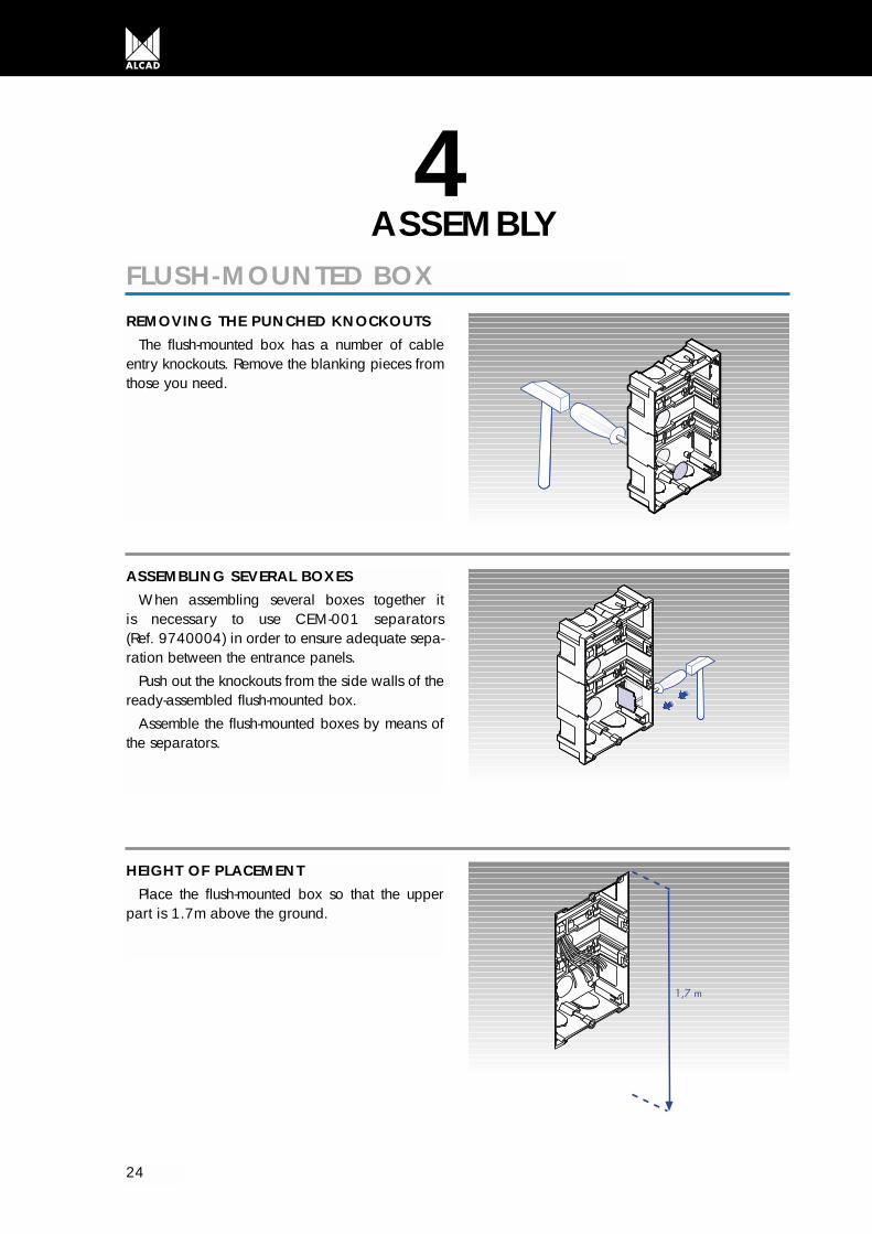
ASSEMBLY4
FLUSH-MOUNTED BOXREMOVING THE PUNCHED KNOCKOUTS
The flush-mounted box has a number of cableentry knockouts. Remove the blanking pieces fromthose you need.
ASSEMBLING SEVERAL BOXES When assembling several boxes together it
is necessary to use CEM-001 separators (Ref. 9740004) in order to ensure adequate sepa-ration between the entrance panels.
Push out the knockouts from the side walls of theready-assembled flush-mounted box.
Assemble the flush-mounted boxes by means ofthe separators.
HEIGHT OF PLACEMENTPlace the flush-mounted box so that the upper
part is 1.7m above the ground.
25
ENTRANCE PANEL
1
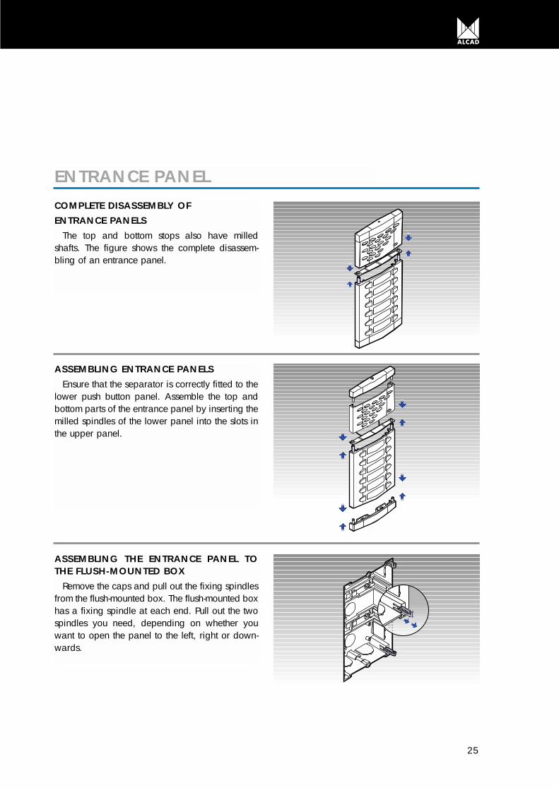
ASSEMBLING ENTRANCE PANELSEnsure that the separator is correctly fitted to the
lower push button panel. Assemble the top andbottom parts of the entrance panel by inserting themilled spindles of the lower panel into the slots inthe upper panel.
COMPLETE DISASSEMBLY OF ENTRANCE PANELS
The top and bottom stops also have milledshafts. The figure shows the complete disassem-bling of an entrance panel.
1
ASSEMBLING THE ENTRANCE PANEL TOTHE FLUSH-MOUNTED BOX
Remove the caps and pull out the fixing spindlesfrom the flush-mounted box. The flush-mounted boxhas a fixing spindle at each end. Pull out the twospindles you need, depending on whether youwant to open the panel to the left, right or down-wards.
26
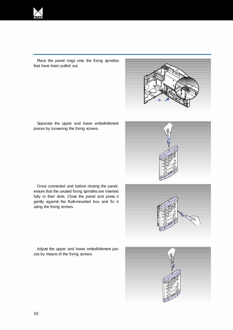
Place the panel rings onto the fixing spindlesthat have been pulled out.
Separate the upper and lower embellishmentpieces by loosening the fixing screws.
Once connected and before closing the panel,ensure that the unused fixing spindles are insertedfully in their slots. Close the panel and press itgently against the flush-mounted box and fix itusing the fixing screws.
Adjust the upper and lower embellishment pie-ces by means of the fixing screws.

27
AUDIO UNIT
PUSH BUTTONS
FITTING THE AUDIO UNITPosition the audio unit lighting push-button and
push to attach the audio unit to the entrancepanel.
REMOVING THE AUDIO UNITUsing a screwdriver, lever the audio unit out
from its fixings.
FITTING PUSH BUTTONSPush to fix the push buttons on to the entrance
panel.
REMOVING PUSH BUTTONSUsing a screwdriver, lever the push button unit
out from its fixings.

28
TELEPHONE
PLACING IDENTIFYING LABELSLever the card holder’s lid up and insert the label
identifying each push button.
REMOVING THE BASE COVERMove the cover of the telephone base to the
right.
Separate the bottom of the cover from the baseof the telephone.
Remove the cover from the telephone base.
29
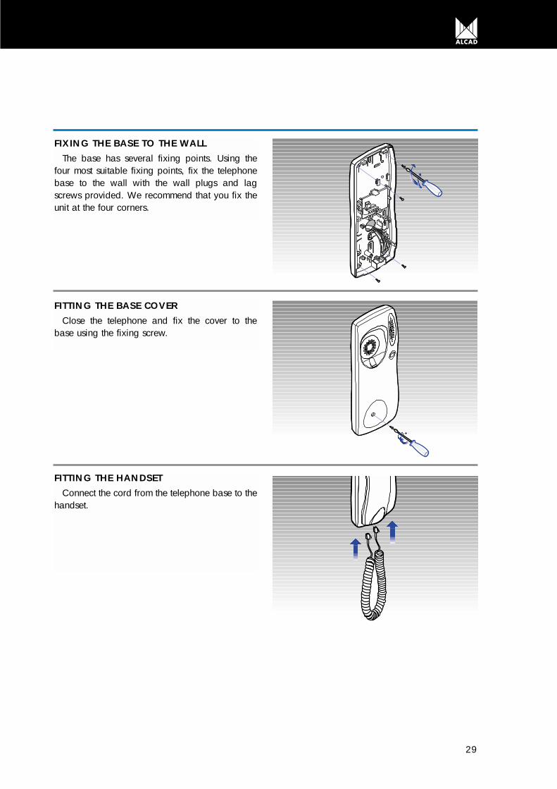
FIXING THE BASE TO THE WALLThe base has several fixing points. Using the
four most suitable fixing points, fix the telephonebase to the wall with the wall plugs and lagscrews provided. We recommend that you fix theunit at the four corners.
FITTING THE BASE COVERClose the telephone and fix the cover to the
base using the fixing screw.
FITTING THE HANDSETConnect the cord from the telephone base to the
handset.

30
POWER SUPPLY
Remember to protect the power supplies (brea-kers, etc) in order to comply with national safetystandards.
WALL MOUNTINGFix the power supply to the wall using the screws
supplied.
FITTING TO A DIN RAILFit the power supply to the DIN rail as shown in
the diagram.
REMOVING FROM DIN RAILTo remove the power supply from the DIN rail,
lever it off with a screw driver, as shown in the diagram.
FIXING THE TERMINAL COVERFix the protective terminal cover using the fixing
screws supplied.

31
CONNECTION AND SET-UP INSTRUCTIONS5
AUDIO UNIT
12 Electric lock
Panel lighting9
Common push button terminal (electronic call)7
Telephone loudspeaker4
Telephone microphone3Telephone common terminal2Door lock release1
Power supply voltageVGround
Panel lighting10
Electric lock11
79 10 11 1212 V~
V~
GRF-001cod. 96101 Made in Spain
J23 2
1 2 3 4
1 2 3 4 79 10 11 12V~
1 2 3 4 79 10 11 12V~
J2
1 2 3 4 79 10 11 12V~
ELECTRONIC AUDIO UNIT GRF-001 Terminal connections
Make the connections to the terminals as indi-cated in the didgram.
Connect the push button common terminal 7, tothe push buttons on the entrance panel.
Connect the entrance panel lighting bulbs to ter-minals 9 and 10.
Audio unit set-upIf you want a tri-tone call, remove jumper J2.
If necessary regulate the volume levels of theentrance panel and the telephones using the vo-lume control potentiometers on the audio unit.
32
AUDIO UNIT
7 89 10 11 1212 V~
V~
Made in Spain
1 2 3 4
GRF-005cod. 96102
12 Electric lock
Electric lock11Panel lighting10Panel lighting9
Common push button terminal (buzzer call)8
Common push button terminal (electronic call)7
Telephone loudspeaker4Telephone microphone3Telephone common terminal2Door lock release1Power supply voltageVGround
1 2 3 4 79 10 11 12V~ 8
81 2 3 4 79 10 11 12V~ 8
1 2 3 4 79 10 11 12V~ 8
J2
1 2 3 4 79 10 11 12V~ 8
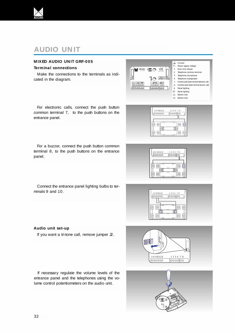
MIXED AUDIO UNIT GRF-005 Terminal connections
Make the connections to the terminals as indi-cated in the diagram.
For electronic calls, connect the push buttoncommon terminal 7, to the push buttons on theentrance panel.
For a buzzer, connect the push button commonterminal 8, to the push buttons on the entrancepanel.
Connect the entrance panel lighting bulbs to ter-minals 9 and 10.
Audio unit set-upIf you want a tri-tone call, remove jumper J2.
If necessary regulate the volume levels of theentrance panel and the telephones using the vo-lume control potentiometers on the audio unit.

33
1 2 3 4 7 16 17 189 10 11 12 13 14 1512 V~
J1
V~
Made in Spain
GRF-003cod. 96104
19 20
GRF-004cod. 96105
18 Principal access common terminalMultiple access17Multiple acces complex16
12 Electronic lockElectronic lock11Panel lighting10Panel lighting9Common push button terminal (electronic call)7Telephone loudspeaker4Telephone microphone3Telephone common terminal2Door lock release1Power supply voltageVGround
1 2 3 4 79 10 11 12V~ 16 1718
1 2 3 4 79 10 11 12V~ 16 1718
1 2 3 4 79 10 11 12V~
J1
13 14 15 16 17 18
AUDIO UNIT MULTI ENTRANCE WITHOUTPRIVACY OF CONVERSATION GRF-003 AUDIO UNIT WITH PRIVACY OF CONVERSATION GRF-004 Terminal connections
Make the connections to the terminals as indi-cated in the diagram.
Connect the push button common terminal 7, tothe push buttons on the entrance panel.
Connect the entrance panel lighting bulbs to ter-minals 9 and 10.
Audio unit set-upThe entrance panel defined as being the syste-
m’s main panel must have jumper J1 in place.Only one main panel can be defined per installa-tion. Therefore, remove jumper J1 from the audiounits of the rest of the panels in the system.
If necessary regulate the volume level of theentrance panel and the telephones using the vo-lume control potentiometers on the audio unit.

34
ELECTRONIC TELEPHONE TEL-001ELECTRONIC TELEPHONE WITH PRIVACYOF CONVERSATION TES-001Terminal connections
Make the connections to the terminals as indi-cated in the diagram.
TELEPHONE
Door lock releaseCommonTelephone microphoneTelephone microphoneElectronic call
Call
Push buttonAudio unit
J1Door lock releaseCommonTelephone microphoneTelephone microphoneElectronic callBuzzer call
Call
Push buttonAudio Unit
A B
Possible positions ofJ1 jumper
UNIVERSAL TELEPHONE TUN-001Terminal connections
Make the connections to the terminals as indi-cated in the diagram.
Telephone set-upFit jumper J1 in position B if your door entry
system is of the separated common lines type.
If necessary, regulate the telephone microphoneand loud speaker volume level to avoid feedbackwith the entrance panel or the telephone itself. Toregulate the volume level use the potentiometerson the telephone base.

35
Terminal connectionsThe power supply must be connected on one
side to the electrical mains and on the other to theentrance panel audio unit. Make the connectionsas shown in the diagram.
POWER SUPPLY
230 V Mains voltageGround (to the audio unit)
V Output voltage (to the audio unit)

36

Wire cross-sectionsWhen wiring the installation observe the cross-section specifications given below. This will ensure the correct
functioning of the door entry system.
If several telephones connected to the same call line are fitted in the dwelling it may be necessary toincrease the wire cross-section in order to maintain sound quality. If so, increase the call wire cross-section inproportion to the number of telephones as follows.
Remember to protect the power supplies (breaker, etc) in order to comply with nationalsafety standards.
37
0.25 mm2
0.5 mm2
0.5 mm2
1 mm2
1 mm2
2 mm2
Common and call cablesPower and electric lock cables
Common and call cablesPower and electric lock cables
Common and call cablesPower and electric lock cables
Telephone
Telephone
Telephone
Up to 150 m
Up to 300 m
Up to 600 m
CIRCUIT DIAGRAMS6
GENERAL POINTS CONCERNING THE INSTALLATION
x 2
x 3
x 4

38
BASIC INSTALLATION WITH ELECTRONIC CALL4+N SYSTEM
Basic circuit diagram of door entry system installa-tion in buildings with a single entrance.Operation
When one of the push buttons on the entrancepanel is pressed the electronic call signal generatedby the audio unit (7) is sent via the call line to thecorresponding telephone (5), where it is heard onthe loudspeaker of the handset. At the same time theaudio unit’s own loudspeaker generates a sound toconfirm to the visitor that the call has been made.
When the handset is picked up the electronicsassociated to the telephone’s audio lines (3 and 4) isinternally connected to the entrance panel. This co-nnection sets up the communication between the tele-phone and the entrance panel.
When the door lock release opener button on thetelephone is pressed, the audio unit detects the clo-sing of the lock release circuit (1). The audio unit thensends an a/c voltage (11 and 12) to the electriclock, thus allowing the entrance door to be opened.
The common wire (2) of the telephone and entran-ce panel provides the return path for all the telepho-ne signals.
V230V230V
4+N
TEL-001
ALA-040
ABR-001
5
2
2
5
5 5
V
MAN-010
MPD-004
MATERIAL REQUIREDMPS-/MPD Push button panel
module (depending on characteristics of the installation)
9670001 MAN - 010 Entrance panel module with electronic audio unit 4+N system
9600001 TEL - 001 Electronic telephones9620001 ALA - 040 Power supply9730000 ABR - 001 Electric lock (other
models available)CMO Flush-mounted box
(depending on cha-racteristics of the installation)
4+N SYSTEM CIRCUIT DIAGRAMS

J2
1 2 3 4 79 10 11 12
230 V230 V
1 2 3 4 5
1 2 3 4 51 2 3 4 5
Calls
CallCall
CallCall
TEL-001
1 2 3 4 5
ALA-040
ABR-001
230 V V~
V
MAN-010
MPD-004
TABLE OF CROSS SECTIONSUp to 150 meters
0,5 mm
0,25 mm
2
2
0,8 mm
0,6 mm
20
22
AWG
39
BASIC INSTALLATION WITH ELECTRONIC CALL4+N SYSTEM

40
MATERIAL REQUIREDMPS-/MPD Push button panel
module (depending on characteristics of the installation)
9670002 MAN - 050 Entrance panel with mixed audio unit 4+N system
9600002 TUN - 001 Universal telephones (electronic/buzzer)
9620001 ALA - 040 Power supply9730000 ABR - 001 Electric lock (other
models available)CMO Flush-mounted box
coepending on characteristics of the installation)
Basic circuit diagram of door entry system installa-tion in buildings with a single entrance.
OperationWhen one of the push buttons on the entrance
panel is pressed the call signal generated by theaudio unit (8) is sent via the call line to the corres-ponding telephone (6) where it is heard. At the sametime the audio unit’s own loudspeaker generates asound to confirm to the visitor that the call has beenmade.
When the handset is picked up the electronicsassociated to the telephone’s audio lines (3 and 4) isinternally connected to the entrance panel. This co-nnection sets up the communication between the tele-phone and the entrance panel.
When the door lock release button on the telepho-ne is pressed, the audio unit detects the closing of thelock release circuit (1). The audio unit then sends ana/c voltage (11 and 12) to the electric lock, thus allo-wing the entrance door to be opened.
The common wire (2) of the telephone and entran-ce panel provides the return path for all the telepho-ne signals.
V230V230V
4+N
TUN-001
ALA-040
ABR-001
5
2
2
5
5 5
V
MAN-050
MPD-004
BASIC INSTALLATION WITH BUZZER CALL4+N SYSTEM

BASIC INSTALLATION WITH BUZZER CALL4+N SYSTEM
41
V
8
1 2 3 4 5 6
J1
1 2 3 4 5 6
J1
1 2 3 4 5 6
J1
1 2 3 4 5 6
J1
J2
1 2 3 4 79 10 11 12
230 V230 V
1 2 3 4 5
1 2 3 4 51 2 3 4 5
Calls
CallCall
CallCall
TUN-001
1 2 3 4 5
ALA-040
ABR-001
230 V V~
MAN-050
MPD-004
8
6
66
6
TABLE CROSS SECTIONSUp to 150 meters
0,5 mm
0,25 mm
2
2
0,8 mm
0,6 mm
20
22
AWG
V

42
EXPANSION OF THE INSTALLATION WITH ADDITIONAL TELEPHONES4+N SYSTEM
UseIt is possible to expand a one dwelling system by
adding telephones (maximum 4 telephones persystem). Each telephone will have the same featuresas the original telephone: call reception, communi-cation with the entrance panel and opening theentrance door.
OperationThe electronic call signal is common to all the tele-
phones. As the call signal is shared between all thetelephones the volume level drops. The call volumealso depends on the cross-sections of the wires used
in the system. If the cross-sections indicated in thismanual are observed, it is possible to install up to 4telephones and still obtain a reasonable call volume.
Material required9600001 TEL-001 Electronic telephones
1 2 3 4 51 2 3 4 51 2 3 4 5
TEL-001

43
UseWhen the entrance door does not have a
handle on the inside push button should be insta-lled to activate the lock release. While the electriclock is activated it is possible to open the door.
OperationWhen the door lock release is pressed, the
audio unit detects the closing of the lock releasecircuit (1). The audio unit then sends an a/c vol-tage (11 and 12) to the electric lock allowing theentrance door to be opened.
The push button is preferable to be fitted near tothe entrance door so that it can be opened whilethe push button is pressed. If this is not possible,an ABR-003 (ref. 9730002) automatic electric
lock which remains released until the door is ope-ned could be fitted.
Material requiredOnly a push button is required.
Basic circuit diagram of door entry system installa-
Opening push button
MPD-004
MAN-010 (Electronic call)MAN-050 (Buzzer call)
ABR-001
1 2 3 4 79 10 11 12V~
J2
TABLE CROSS SECTIONSUp to150 meters
0,5 mm
0,25 mm
2
2
0,8 mm
0,6 mm
20
22
AWG
OPENING THE DOOR FROM INSIDE THE BUILDING4+N SYSTEM

tion in buildings with a single entrance.
OperationWhen one of the push buttons on the entrance
panel is pressed the electronic call signal generatedby the audio unit (7) is sent via the call line to thecorresponding telephone (5), where it is heard onthe loudspeaker of the handset. At the same time theaudio unit’s own loudspeaker generates a sound toconfirm to the visitor that the call has been made.
When the handset is picked up the electronicsassociated to the telephone’s audio lines (3 and 4) isinternally connected to the entrance panel. This co-nnection sets up the communication between the tele-phone and the entrance panel.
When the door lock release button on the telepho-ne is pressed, the audio unit detects the closing of thelock release circuit (1). The audio unit then sends ana/c voltage (11 and 12) to the electric lock, thus allo-wing the entrance door to be opened.
The common wire (2) of the telephone and entran-ce panel provides the return path for all the telepho-ne signals.
Basic circuit diagram of door entry system installation
V230V230V
4+N
TEL-001
ALA-040
ABR-001
5
2
2
5
5 5
V
MAN-030
MPD-004
BASIC INSTALLATION WITH ELECTRONIC CALLMICROPROCESSOR-BASED 4+N SYSTEM
44
MATERIAL REQUIREDMPS-/MPD Push button panel
module (depending on characteristics of the installation)
9670004 MAN - 030 Entrance panel with audio unit multi entrance without privacy of conversation, 4+N system
9600001 TEL - 001 Electronic telephones 9620001 ALA - 040 Power supply9730000 ABR - 001 Electric lock (other
models available)CMO Flush-mounted box
(depending on characteristics of the installations)
MICROPROCESSOR-BASED 4+N SYSTEM CIRCUIT DIAGRAMS

45
BASIC INSTALLATION WITH ELECTRONIC CALLMICROPROCESSOR-BASED 4+N SYSTEM
230 V230 V
1 2 3 4 5
1 2 3 4 51 2 3 4 5
Calls
CallCall
CallCall
TEL-001
1 2 3 4 5
ALA-040
ABR-001
230 V 9 1 2 3 4 710 11 12 13 14 15 16 17 18
19 20
V~
V
MAN-030
MPD-004
J1
TABLE CROSS SECTIONSUp to 150 meters
0,5 mm
0,25 mm
2
2
0,8 mm
0,6 mm
20
22
AWG
46
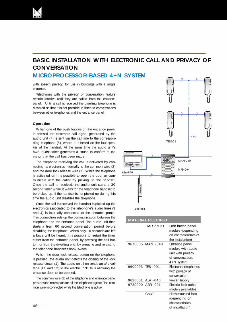
MATERIAL REQUIREDMPS-/MPD Push button panel
module (depending on characteristics of the installation)
9670005 MAN - 040 Entrance panel module with audio unit with privacy of conversation, 4+N system
9600003 TES - 001 Electronic telephones with privacy of conversation
9620001 ALA - 040 Power supply9730000 ABR - 001 Electric lock (other
models available)CMO Flush-mounted box
(depending on characteristics of installation)
with speech privacy, for use in buildings with a singleentrance.
Telephones with the privacy of conversation featureremain inactive until they are called from the entrancepanel. Until a call is received the dwelling telephone isdisabled so that it is not possible to listen to conversationsbetween other telephones and the entrance panel.
OperationWhen one of the push buttons on the entrance panel
is pressed the electronic call signal generated by theaudio unit (7) is sent via the call line to the correspon-ding telephone (5), where it is heard on the loudspea-ker of the handset. At the same time the audio unit’sown loudspeaker generates a sound to confirm to thevisitor that the call has been made.
The telephone receiving the call is activated by con-necting its electronics internally to the common wire (2)and the door lock release wire (1). While the telephoneis activated on it is possible to open the door or com-municate with the caller by picking up the handset.Once the call is received, the audio unit starts a 30second timer while it waits for the telephone handset tobe picked up. If the handset is not picked up during thistime the audio unit disables the telephone.
Once the call is received the handset is picked up theelectronics associated to the telephone’s audio lines (3and 4) is internally connected to the entrance panel.This connection sets up the communication between thetelephone and the entrance panel. The audio unit thenstarts a fresh 60 second conversation period beforedisabling the telephone. When only 10 seconds are lefta buzz will be heard. It is possible to restart the timereither from the entrance panel, by pressing the call but-ton, or from the dwelling end, by pressing and releasingthe telephone handset’s hook switch.
When the door lock release button on the telephoneis pressed, the audio unit detects the closing of the lockrelease circuit (1). The audio unit then sends an a/c vol-tage (11 and 12) to the electric lock, thus allowing theentrance door to be opened.
The common wire (2) of the telephone and entrance panelprovides the return path for all the telephone signals. The com-mon wire is connected while the telephone is active.
V230V230V
4+N
TES-001
ALA-040
ABR-001
5
2
2
5
5 5
V
MAN-040
MPD-004
BASIC INSTALLATION WITH ELECTRONIC CALL AND PRIVACY OFCONVERSATIONMICROPROCESSOR-BASED 4+N SYSTEM

230 V230 V
1 2 3 4 5
1 2 3 4 51 2 3 4 5
Calls
CallCall
CallCall
TES-001
1 2 3 4 5
ALA-040
ABR-001
230 V 9 1 2 3 4 710 11 12 13 14 15 16 17 18V~
V
MAN-040
MPD-004
19 20J1
TABLE CROSS SECTIONUp to 150 meters
0,5 mm
0,25 mm
2
2
0,8 mm
0,6 mm
20
22
AWG
47
BASIC INSTALLATION WITH ELECTRONIC CALL AND PRIVACY OFCONVERSATIONMICROPROCESSOR-BASED 4+N SYSTEM

48
Basic circuit diagram of door entry system insta-llation in buildings with two entrances.
Alcad multiple entrance systems are based onthe use of microprocessor-controlled audio units(microprocessor-based 4+N system). Rather thanusing changeover switches to select one of theentrance panels, the audio unit has been fittedwith a microprocessor that decides which entran-ce panel should be activated, and deactivates therest of the panels in the system.
This system simplifies the cabling of the installa-tion, reduces the number of components andimproves system operation.Operation
One of the entrance panels in the system is chosento be the main panel just one panel per installationcan be defined as the main one. To select it, removejumper J1 from the other entrance panel. The mainpanel is the one which is connected by default to thesystem’s telephones. The other panel is only activatedwhen one of the call buttons is pressed.
When a call button is pressed, the correspondingpanel comes on to allow communication with thetelephones. The system busy indicator light on theother panel will start to flash to indicate that it is disa-bled.
When a push button on one of the entrance panelsis pressed the electronic call signal generated by theaudio unit (7) is sent via the call line to the corres-ponding telephone (5), where it is heard on theloudspeaker of the handset. At the same time theaudio unit’s own loudspeaker generates a sound toconfirm to the visitor that the call has been made. Theaudio unit also generates a control signal (17) thatdisables the other entrance panel.
The audio unit starts a 30 second timer while itwaits for the telephone handset to be picked up. Ifthe handset is not picked up during this time, the con-trol signal (17) is removed and both panels go intothe standby state.
If the handset is picked up during this time, theelectronics associated to the telephone’s audio lines
(3 and 4) is internally connected to the entrancepanel. This connection sets up the communicationbetween the telephone and the entrance panel. Theaudio unit starts a fresh 60 second period beforeremoving the control signal (17) and putting bothpanels into standby state. When only 10 secondsare left a buzz will be heard. It is possible to restartthe timer from the dwelling end by pressing and rele-asing the telephone handset’s hook switch. After fini-shing the communication, when the audio unitdetects that the telephone handset has been hung up,it removes the control signal (17) and both panels gointo the standby state.
When the door lock release button on the telepho-ne is pressed, the audio unit of the active paneldetects the closing of the lock release circuit (1). Theaudio unit then sends an a/c voltage (11 and 12) tothe electric lock connected to the active entrancepanel, thus allowing the entrance door to be ope-ned.
The common wire (2) of the telephone and entran-ce panel provides the return path for all the telepho-ne signals.
TWO ENTRANCE INSTALLATION WITH ELECTRONIC CALLMICROPROCESSOR-BASED 4+N SYSTEM

V V
6+N
230V230V230V230V
22
4+N
TEL-001
55
5 5
ABR-001
2 2
ABR-001
ALA-040
ALA-040
V V
MAN-030
MPD-004
MAN-030
MPD-004
49
MATERIAL REQUIREDMPS -/MPD Push button panel
module (depending on characteristics of the installation)
9670004 MAN - 030 Entrance panel module with audio unit multi entrance without privacy of conversation, 4+N system
9600001 TEL - 001 Electronic telephones9620001 ALA - 040 Power supply9730000 ABR - 001 Electric lock (other
models available)CMO Flush mounted box
(depending on characte-ristics of the installation)
TWO ENTRANCE INSTALLATION WITH ELECTRONIC CALLMICROPROCESSOR-BASED 4+N SYSTEM

50
TWO ENTRANCE INSTALLATION WITH ELECTRONIC CALLMICROPROCESSOR-BASED 4+N SYSTEM
9 1 2 3 4 710 11 12 13 14 15 16 17 189 1 2 3 4 710 11 12 13 14 15 16 17 18
230 V230 V
1 2 3 4 51 2 3 4 5
1 2 3 4 5 1 2 3 4 5
Call
CallCall
CallCall
TEL-001
ABR-001
ALA-040230 V
230 V230 V
Call
ALA-040230 V
ABR-001
V~ V~
V V
MAN-030
MPD-004
MAN-030
MPD-004
19 20J1
19 20J1
TABLE CROSS SECTIONSUp to 150 meters
0,5 mm
0,25 mm
2
2
0,8 mm
0,6 mm
20
22
AWG
51
Basic circuit diagram of door entry system insta-llation in buildings with three entrances. Alcad mul-tiple entrance systems are based on the use ofmicroprocessor-controlled audio units (microproces-sor-based 4+N system). Rather than using change-over switches to select one of the entrance panels,the audio unit has been fitted with a microprocessorthat decides which entrance panel should be acti-vated, and deactivates the rest of the panels in thesystem.
This system simplifies the cabling of the installa-tion, reduces the number of components and impro-ves system operation.
OperationOne of the entrance panels in the system is cho-
sen to be the main panel just one panel per insta-llation can be defined as the main one. To selectit, remove jumper J1 from the other entrancepanel. The main panel is the one which is con-nected by default to the system’s telephones. Theother panels are only activated when one of thecall buttons is pressed.
When a call button is pressed, the correspon-ding panel is activated to allow communicationwith the telephones. The system busy indicator onthe other panels will start to flash to indicate thatthey are disabled.
When a push button on one of the entrancepanels is pressed, the electronic call signal gene-rated by the audio unit (7) is sent via the call lineto the corresponding telephone (5), where it isheard on the loudspeaker of the handset. At thesame time the audio unit’s own loudspeaker gene-rates a sound to confirm to the visitor that the callhas been made. The audio unit also generates acontrol signal (17) that disables the other entrancepanels.
The audio unit starts a 30 second timer while itwaits for the telephone handset to be picked up. Ifthe handset is not picked up during this time, thecontrol signal (17) is removed and all three panelsgo into the standby state.
If the handset is picked up during this time, theelectronics associated to the telephone’s audiolines (3 and 4) is internally connected to theentrance panel. This connection sets up the com-munication between the telephone and the entran-ce panel. The audio unit starts a fresh 60 secondperiod before removing the control signal (17)and putting all three panels into standby state.When only 10 seconds are left a buzz will beheard. It is possible to restart the timer from thedwelling end by pressing and releasing the tele-phone hook switch. After finishing the communi-cation, when the audio unit detects that the tele-phone handset has been hung up, it removes thecontrol signal (17) and all three panels go into thestandby state.
When the door lock release button on the tele-phone is pressed, the active audio unit detects theclosing of the lock release circut (1). The audiounit then sends an a/c voltage (11 and 12) to theelectric lock connected to the active entrancepanel, thus allowing the entrance door to be ope-ned.
The common wire (2) of the telephone andentrance panel provides the return path for all thetelephone signals.
THREE ENTRANCE INSTALLATION WITH ELECTRONIC CALLMICROPROCESSOR-BASED 4+N SYSTEM

52
230 V230 V230 V230 V230 V230 V
6+N
ABR-001
2
6+N
2
TEL-001
4+N
55
5 5
ABR-001
2
2
ABR-001
2
2
VVV
ALA-040
MAN-030
MPD-004
ALA-040
MAN-030
MPD-004
ALA-040
MAN-030
MPD-004
THREE ENTRANCE INSTALLATION WITH ELECTRONIC CALLMICROPROCESSOR-BASED 4+N SYSTEM
MATERIAL REQUIREDMPS-/MPD Push button panel
module (depending on characteristics of the installation)
9670004 MAN - 030 Entrance panel module with audio unit multi entrance (without privacy of conversation), 4+N system
9600001 TEL - 001 Electronic telephones9620001 ALA - 040 Power supply9730000 ABR - 001 Door opener (other
models available)CMO Flush-mounted box
(depending on characteristics of the installation

53
9 1 2 3 4 710 11 12 13 14 15 16 17 18
V V V
9 1 2 3 4 710 11 12 13 14 15 16 17 189 1 2 3 4 710 11 12 13 14 15 16 17 18
230 V V
1 2 3 4 51 2 3 4 5
1 2 3 4 51 2 3 4 5
Call
CallCall
TEL-001
ABR-001
ALA-040
CallCall
230 V
230 V230 V
Call
ABR-001
ALA-040230 V
230 V230 V
Call
ABR-001
ALA-040230 V
MAN-030
MPD-004
MAN-030
MPD-004
MAN-030
MPD-004
V V
V V V
19 20J1
19 20J1
19 20J1
TABLE CROSS SECTIONSUp to150 meters
0,5 mm
0,25 mm
2
2
0,8 mm
0,6 mm
20
22
AWG
THREE ENTRANCE INSTALLATION WITH ELECTRONIC CALLMICROPROCESSOR-BASED 4+N SYSTEM

54
Basic circuit diagram of a door entry system insta-llation in a complex with several blocks.
Alcad multiple entrance systems are based on theuse of microprocessor-controlled audio units (micro-processor-based 4+N system). Rather than usingchangeover switches to select one of the entrancepanels, the audio unit has been fitted with a micro-processor that decides which entrance panel shouldbe activated, and deactivates the rest of the panels inthe system.
This system simplifies the cabling of the installation,reduces the number of components and improvessystem operation.
This type of installation can be treated as several ins-tallations with two entrances each joined together. Onthe main entrance to the complex or residential thereare as many entrance panels as buildings inside thecomplex. Thus, each entrance panel at the mainentrance is associated dust with the entrance panel ofone of the buildings. Each pair of panels works in thesame way as a two-entrance installation.
OperationEach entrance panel at the main entrance end is
selected as the main panel of the system. Just onepanel per installation can be defined as the main one.To select it, remove jumper J1 from the buildingsentrance panels. The main panel is the one which isconnected by default to the system’s telephones. Theother panels are only activated when one of the callbuttons is pressed.
When a call button is pressed, the correspondingpanel is activated to allow communication with thetelephones. The system busy indicator light on theassociated panel will start to flash to indicate that it isdisabled. If the call is made from an entrance panelfrom the main entrance to the residential, it´s possibleto disable not only the building associated to thatpanel but also the rest of the panels of the main entran-ce. To do so the various panels need to be interco-nnected via terminal 16.
When one of the push buttons on one of the entran-ce panels is pressed the electronic call signal genera-ted by the audio unit (7) is sent via the call line to thecorresponding telephone (5), where it is heard on theloudspeaker of the handset. At the same time theaudio unit’s own loudspeaker generates a sound toconfirm to the visitor that the call has been made. Theaudio unit also generates a control signal (17) thatdeactivates the associated entrance panel. When thevisitor is calling from the main entrance, the audio unitgenerates a control signal (16) which disables the restof the panels at the entrance.
The audio unit starts a 30 second timer while it waitsfor the telephone handset to be picked up. If the hand-set is not picked up during this time, the control signal(17) and (16) (in the case of the main entrance) isremoved and the panels go into the standby state.
If the handset is picked up during this time, the elec-tronics associated to the telephone’s audio lines (3and 4) is internally connected to the entrance panel.This connection sets up the communication betweenthe telephone and the entrance panel. The audio unitstarts a fresh 60 second period before removing thecontrol signals (17) and (16) (in the case of the mainentrance) and putting the panels into standby state.When only 10 seconds are left a buzz will be heard.It is possible to restart the timer from the dwelling endby pressing and releasing the telephone handset’shook switch. After finishing the communication, whenthe audio unit detects that the telephone handset hasbeen hung up, it removes the control signals (17) and(16) (in the case of the main entrance) and the panelsgo into the standby state.
When the door lock release button on the telepho-ne is pressed, the active audio unit detects the closingof the lock release circuit (1). The audio unit thensends an a/c voltage (11 and 12) to the electric lockconnected to the active entrance panel, thus allowingthe entrance door to be opened.
The common wire (2) of the telephone and entran-ce panel provides the return path for all the telephonesignals.
INSTALLATION WITH ELECTRONIC CALL IN A COMPLEX WITH SEVERAL BLOCKSMICROPROCESSOR-BASED 4+N SYSTEM

55
MATERIAL REQUIREDMPS-/MPD Push button panel
module (depending on characteristics of the installation)
9670004 MAN - 030 Entrance panel module with audio unit multi entrance (without privacy of conversation), 4+N system
9600001 TEL - 001 Electronic telephones9620001 ALA - 040 Power supply9730000 ABR - 001 Electric lock (other
models available)ABR - 001 Flush-mounted box
(depending on characteristics of the installation)
9740004 CEM - 001 Flush-mounted box set of separators
ABR-001
TEL-001
55
5 5
4+N
55
5 5
ALA-040
2
22
TEL-001
55
5 5
4+N
ALA-040
2
2
ABR-001
2
6+N
230 V230 V
2
230 V230 V
2
22
TEL-001
ALA-040
ALA-040
ABR-001
ABR-001
2
2
6+N 6+N
4+N
V
V230 V230 V V 230 V230 V V
MAN-030 X 3
MPD-004 X 3
MAN-030
MPD-004
MAN-030
MPD-004
MAN-030
MPD-004
BUILDING A BUILDING B BUILDING C
INSTALLATION WITH ELECTRONIC CALL IN A COMPLEX WITH SEVERAL BLOCKSMICROPROCESSOR-BASED 4+N SYSTEM

9 1 2 3 4 710 11 12 13 14 15 16 17 18
Call
9 1 2 3 4 710 11 12 13 14 15 16 17 18 9 1 2 3 4 710 11 12 13 14 15 16 17 189 1 2 3 4 710 11 12 13 14 15 16 17 18
230 V230 V
230 V230 V
Call
ABR-001
TEL-001 TEL-001
1 2 3 4 5
TEL-001
ALA-040
230 V
ABR-001
ALA-040
230 V
230 V230 V
ALA-040
ABR-001
230 V230 V
ALA-040
ABR-001
Call
V
V V
V
MAN-030 X 3
MPD-004 X 3
MAN-030
MPD-004
MAN-030
MPD-004
MAN-030
MPD-004
19 20J1
19 20J1
19 20J1
V V V
V
19 20J1
TABLE CROSS SECTIONSUp to150 meters
0,5 mm
0,25 mm
2
2
0,8 mm
0,6 mm
20
22
AWG
BUILDING A
COMMON ACCESS
CallBUILDING B
CallBUILDING C
BUILDING A BUILDING B
BUILDING CBUILDING C
56
INSTALLATION WITH ELECTRONIC CALL IN A COMPLEX WITH SEVERAL BLOCKSMICROPROCESSOR-BASED 4+N SYSTEM

57
Basic circuit diagram of door entry system insta-llation with speech privacy, for use in buildings withtwo entrances.
Alcad multiple entrance systems are based on theuse of microprocessor-controlled audio units (micro-processor-based 4+N system). Rather than usingchangeover switches to select one of the entrancepanels, the audio unit has been fitted with a micro-processor that decides which entrance panel shouldbe activated, and disables the rest of the panels inthe system.
This system simplifies the cabling of the installa-tion, reduces the number of components and impro-ves system operation.
Telephones with the privacy of conversation featu-re remain inactive until they are called from theentrance panel. Until a call is received the dwellingtelephone is disabled so that it is not possible to lis-ten to conversations between other tele-phones andthe entrance panel.
OperationOne of the entrance panels in the system is chosen
to be the main panel just one panel per installationcan be defined as the main one. To select it, removejumper J1 from the other entrance panel. The mainpanel is the one which is connected by default to thesystem’s telephones. The other panel is only activa-ted when one of the call buttons is pressed.
When a call button is pressed, the correspondingpanel is activated to allow communication with thetelephones. The system busy indicator light on otherpanel will start to flash to indicate that it is disabled.
When one of the push buttons on one of theentrance panels is pressed the electronic call signalgenerated by the audio unit (7) is sent via the callline to the corresponding telephone (5), where it isheard on the loudspeaker of the handset. At thesame time the audio unit’s own loudspeaker gene-
rates a sound to confirm to the visitor that the call hasbeen made. The audio unit also generates a controlsignal (17) that disables the other entrance panel.
The telephone that receives the call is activated byconnecting its electronics internally to the commonwire (2) and the door lock wire (1). While the tele-phone is activated on it is possible to open the dooror communicate with the caller by picking up thehandset. Once the call is received, the audio unitstarts a 30 second timer while it waits for the tele-phone handset to be picked up. If the handset is notpicked up during this time, the control signal (17) isremoved and both panels go into the standby state.
If the handset is picked up during this time, theelectronics associated the telephone’s audio lines (3and 4) is internally connected to the entrance panel.This connection sets up the communication betweenthe telephone and the entrance panel. The audiounit starts a fresh 60 second period before disablingthe telephone and removing the control signal (17),putting both panels into standby state. When only10 seconds are left a buzz will be heard. It is possi-ble to restart the timer either from the entrancepanel, by pressing the push button, or from the dwe-lling end, by pressing and releasing the telephonehandset’s hook switch. After finishing the communi-cation, when the audio unit detects that the telepho-ne handset has been hung up, it removes the controlsignal (17) and both panels go into the standbystate.
When the door lock release button on the tele-phone is pressed, the audio unit detects the closingof the lock release circuit (1). The audio unit thensends an a/c voltage (11 and 12) to the electric lockconnected to the active entrance panel, thus allo-wing the entrance door to be opened.
The common wire (2) of the telephone and entran-ce panel provides the return path for all the telepho-ne signals. The common wire is connected while thetelephone is active.
TWO ENTRANCE INSTALLATION WITH ELECTRONIC CALLAND PRIVACY OF CONVERSATIONMICROPROCESSOR-BASED 4+N SYSTEM

58
TWO ENTRANCE INSTALLATION WITH ELECTRONIC CALLAND PRIVACY OF CONVERSATIONMICROPROCESSOR-BASED 4+N SYSTEM
V V
6+N
230 V230 V230 V230 V
22
4+N
TES-001
55
5 5
ABR-001
2 2
ABR-001
ALA-040 ALA-040
V V
MAN-040
MPD-004
MAN-040
MPD-004
MATERIAL REQUIREDMPS - /MPD Push button panel
module(depending on characteristics of the installation)
9670005 MAN - 040 Entrance panel with audio unit (with privacy of conversation),4+N system
9600003 TES - 001 Electronic telephones with privacy of conversation
9620001 ALA - 040 Power supply9730000 ABR - 001 Electric lock (other
models available)CMO Flush-mounted box
(depending on characteristics of the installation)

59
TWO ENTRANCE INSTALLATION WITH ELECTRONIC CALLAND PRIVACY OF CONVERSATIONMICROPROCESSOR-BASED 4+N SYSTEM
9 1 2 3 4 710 11 12 13 14 15 16 17 189 1 2 3 4 710 11 12 13 14 15 16 17 18
230 V230 V
1 2 3 4 51 2 3 4 5
1 2 3 4 5 1 2 3 4 5
Call
CallCall
CallCall
TES-001
ABR-001
ALA-040230 V
230 V230 V
ALA-040230 V
ABR-001
V~ V~
V V
MAN-040
MPD-004
MAN-040
MPD-004
19 20J1
19 20J1
TABLE CROSS SECTIONSUp to 150 meters
0,5 mm
0,25 mm
2
2
0,8 mm
0,6 mm
20
22
AWG

60
Basic circuit diagram of door entry system installa-tion with speech privacy, for use in buildings withthree entrances.
Alcad multiple entrance systems are based on theuse of microprocessor-controlled audio units (micro-processor-based 4+N system). Rather than usingchangeover switches to select one of the entrancepanels, the audio unit has been fitted with a micro-processor that decides which entrance panel shouldbe activated, and deactivates the rest of the panelsin the system.
This system simplifies the cabling of the installation,reduces the number of components and improvessystem operation.
Telephones with the privacy of conversation featu-re remain inactive until they are called from theentrance panel. Until a call is received the dwellingtelephone is disabled. It is therefore not possible tolisten to conversations between other tele-phones andthe entrance panel.
OperationOne of the entrance panels in the system is chosen
to be the main panel just one panel per installationcan be defined as the main one. To select it, removejumper J1 from the other entrance panels. The mainpanel is the one which is connected by default to thesystem’s telephones. The other panels are only acti-vated when one of the call buttons is pressed.
When a call button is pressed, the correspondingpanel comes on to allow communication with thetelephones. The system busy indicator light on theother panels will start to flash to indicate that they aredisabled.
When one of the push buttons on one of theentrance panels is pressed the electronic call signalgenerated by the audio unit (7) is sent via the call lineto the corresponding telephone (5), where it is heardon the loudspeaker of the handset. At the same timethe audio unit’s own loudspeaker generates a soundto confirm to the visitor that the call has been made.
The audio unit also generates a control signal (17)that deactivates the other entrance panels.
The telephone that receives the call is activated byconnecting its electronics internally to the commonwire (2) and the door lock release wire (1). Whilethe telephone is activated it is possible to open thedoor or communicate with the caller by picking upthe handset. Once the call is received, the audio unitstarts a 30 second timer while it waits for the tele-phone handset to be picked up. If the handset is notpicked up during this time, the control signal (17) isremoved and all three panels go into the standbystate.
If during this time the handset is picked up the elec-tronics associated to the telephone’s audio lines (3and 4) is internally connected to the entrance panel.This connection sets up the communication betweenthe telephone and the entrance panel. The audio unitstarts a fresh 60 second period before disabling thetelephone and removing the control signal (17), pu-tting all three panels into standby state. When only10 seconds are left a buzz will be heard. It is possi-ble to restart the timer either from the entrance panel,by pressing the push button, or from the dwellingend, by pressing and releasing the telephone hand-set’s hook switch. After finishing the communication,when the audio unit detects that the telephone hand-set has been hung up, it removes the control signal(17) and all three panels go into the standby state.
When the door lock release button on the telepho-ne is pressed, the audio unit of the active paneldetects the closing of the lock release circuit (1). Theaudio unit then sends an a/c voltage (11 and 12) tothe electric lock connected to the active entrancepanel, thus allowing the entrance door to be ope-ned.
The common wire (2) of the telephone and entran-ce panel provides the return path for all the telepho-ne signals. The common wire is connected while thetelephone is active.
THREE ENTRANCE INSTALLATION WITH ELECTRONIC CALLAND PRIVACY OF CONVERSATIONMICROPROCESSOR-BASED 4+N SYSTEM

61
230 V230 V230 V230 V230 V230 V
6+N
ABR-001
2
6+N
2
TES-001
4+N
55
5 5
ABR-001
2
2
ABR-001
2
2
VVV
ALA-040
MAN-040
MPD-004
ALA-040
MAN-040
MPD-004
ALA-040
MAN-040
MPD-004
THREE ENTRANCE INSTALLATION WITH ELECTRONIC CALLAND PRIVACY OF CONVERSATIONMICROPROCESSOR-BASED 4+N SYSTEM
MATERIAL REQUIREDMPS-/MPD Push button panel
module (depending on characteristics of the installation)
9670005 MAN - 040 Entrance panel modulewith audio unit (with privacy of conver-sation), 4+N system
9600003 TES - 001 Electronic telephones with privacy of conversation
9620001 ALA - 040 Power supply9730000 ABR - 001 Electric lock (other
models available)CMO Flush-mounted box
(depending on characteristics of the installation)

9 1 2 3 4 710 11 12 13 14 15 16 17 18
V V V
9 1 2 3 4 710 11 12 13 14 15 16 17 189 1 2 3 4 710 11 12 13 14 15 16 17 18
230 V V
1 2 3 4 51 2 3 4 5
1 2 3 4 51 2 3 4 5
Call
CallCall
TES-001
ABR-001
ALA-040
CallCall
230 V
230 V230 V
Call
ABR-001
ALA-040230 V
230 V230 V
Call
ABR-001
ALA-040230 V
MAN-040
MPD-004
MAN-040
MPD-004
MAN-040
MPD-004
V V
V V V
19 20J1
19 20J1
19 20J1
TABLE CROSS SECTIONSUp to 150 meters
0,5 mm
0,25 mm
2
2
0,8 mm
0,6 mm
20
22
AWG
62
THREE ENTRANCE INSTALLATION WITH ELECTRONIC CALLAND PRIVACY OF CONVERSATIONMICROPROCESSOR-BASED 4+N SYSTEM

63
Basic circuit diagram of a door entry system installationwith an electronic call and speech privacy in a complex withseveral blocks.
Alcad multiple entrance systems are based on the use ofmicroprocessor-controlled audio units (microprocessor-based4+N system). Rather than using changeover switches toselect one of the entrance panels, the audio unit has been fi-tted with a microprocessor that decides which entrancepanel should be activated, and deactivates the rest of thepanels in the system.
This system simplifies the cabling of the installation, reduces the number of components and improves systemoperation.
This type of installation can be treated as several installa-tions with two entrances each joined together. On the mainentrance to the complex or residential there are as manyentrance panels as buildings inside the complex. Thus, eachentrance panel at the main entrance is associated with theentrance panel of one of the buildings. Each pair of panelsworks in the same way as a two entrance installation.
Telephones with the privacy of conversation featureremain inactive until they are called from the entrance panel.From a disabled telephone which has not received the callit is not possible to hear the conversations between other tele-phones and the entrance panels.
OperationEach entrance panel at the main entrance end is selected
as the main panel of the system just one panel per installa-tion, can be defined as the main one. To select it, removejumper J1 from the building entrance panels. The main panelis the one which is connected by default to the system’s tele-phones. The other panels are only activated when one of thecall buttons is pressed.
When a call button is pressed, the corresponding panelcomes on to allow communication with the telephones. Thesystem busy indicator light on the associated panel will startto flash to indicate that it is disabled. If the call is made froman entrance panel from the main entrance to the residential,it´s possible to disable not only the building associated tothat panel but also the rest of the panels of the main entran-ce. To do so the various panels need to be interconnectedvia terminal 16.
When one of the push buttons on one of the entrance
panels is pressed the electronic call signal generated by theaudio unit (7) is sent via the call line to the correspondingtelephone (5), where it is heard on the loudspeaker of thehandset. At the same time the audio unit’s own loudspeakergenerates a sound to confirm to the visitor that the call hasbeen made. The audio unit also generates a control signal(17) and (16) (in the case of the main entrance panel) thatdeactivates the associated entrance panel. When the visitoris calling from the main entrance, the audio unit generates acontrol signal (16) which disables the rest of the panels atthe entrance.
The telephone that receives the call is activated by co-nnecting its electronics internally to the common wire (2) andthe door lock release wire (1). While the telephone is acti-vated on it is possible to open the door or communicate withthe caller by picking up the handset. Once the call is recei-ved, the audio unit starts a 30 second timer while it waits forthe telephone handset to be picked up. If the handset is notpicked up during this time, the telephone is disabled and thecontrol signals (17) and (16) (in the case of the main entran-ce) are removed, and all the panels go into the standbystate.
If the handset is picked up during this time, the electronicsassociated to the telephone’s audio lines (3 and 4) is inter-nally connected to the entrance panel. This connection sestup the communication between the telephone and theentrance panel. The audio unit starts a fresh 60 secondperiod before removing the control signals (17) and (16) (inthe case of the main entrance) and the panels go intostandby. When only 10 seconds are left a buzz will beheard. It is possible to restart the timer either from the entran-ce panel, by pressing the push button, or from the dwellingend, by pressing and releasing the telephone handset’s hookswitch. After finishing the communication, when the audiounit detects that the telephone handset has been hung up, itremoves the control signals (17) and (16) (in the case of themain entrance) and the panels go into the standby state.
When the door lock release button on the telephone ispressed, the active audio unit detects the closing of the lockrelease circuit (1). The audio unit then sends an a/c voltage(11 and 12) to the electric lock connected to the activeentrance panel, thus allowing the entrance door to be ope-ned.
The common wire (2) of the telephone and entrance panelprovides the return path for all the telephone signals.
INSTALLATION WITH ELECTRONIC CALL AND PRIVACY OF CONVERSATION IN A COMPLEX WITH SEVERAL BLOCKSMICROPROCESSOR-BASED 4+N SYSTEM

64
ABR-001
TES-001
55
5 5
4+N
55
5 5
ALA-040
2
22
TES-001
55
5 5
4+N
ALA-040
2
2
ABR-001
2
6+N
230 V230 V
2
230 V230 V
2
22
TES-001
ALA-040
ALA-040
ABR-001
ABR-001
2
2
6+N 6+N
4+N
V
V230 V230 V V 230 V230 V V
MAN-040 X 3
MPD-004 X 3
MAN-040
MPD-004
MAN-040
MPD-004
MAN-040
MPD-004
INSTALLATION WITH ELECTRONIC CALL AND PRIVACY OF CONVERSATION IN A COMPLEX WITH SEVERAL BLOCKSMICROPROCESSOR-BASED 4+N SYSTEM
MATERIAL REQUIREDMPS-/MPD Push button panel
module (depending on characteristics of the installation)
9670005 MAN - 040 Entrance panel with audio unit (with privacy of conversation), 4+N system
9600003 TES - 001 Electronic telephones with privacy of conversation
9620001 ALA - 040 Power supply9730000 ABR - 001 Electric lock (other
models available)CMO Flush-mounted box
(depending on characteristics of the installation)

65
INSTALLATION WITH ELECTRONIC CALL AND PRIVACY OF CONVERSATION IN A COMPLEX WITH SEVERAL BLOCKSMICROPROCESSOR-BASED 4+N SYSTEM
9 1 2 3 4 710 11 12 13 14 15 16 17 18
Call
9 1 2 3 4 710 11 12 13 14 15 16 17 18 9 1 2 3 4 710 11 12 13 14 15 16 17 189 1 2 3 4 710 11 12 13 14 15 16 17 18
230 V230 V
230 V230 V
Call
ABR-001
TES-001 TES-001
1 2 3 4 5
TES-001
ALA-040
230 V
ABR-001
ALA-040
230 V
230 V230 V
ALA-040
ABR-001
230 V230 V
ALA-040
ABR-001
Call
V
V V
V
MAN-040 X 3
MPD-004 X 3
MAN-040
MPD-004
MAN-040
MPD-004
MAN-040
MPD-004
19 20J1
19 20J1
19 20J1
V V V
V
19 20J1
TABLE CROSS SECTIONSUp to 150 meters
0,5 mm
0,25 mm
2
2
0,8 mm
0,6 mm
20
22
AWG
BUILDING A
COMMON ACCESS
CallBUILDING B
CallBUILDING C
BUILDING A BUILDING B
BUILDING CBUILDING C

66
UseIt is possible to expand a one dwelling system by
adding telephones (maximum 4 telephones persystem). Each telephone will have the same featuresas the original telephone: call reception, communi-cation with the entrance panel and opening theentrance door. In order to ensure adequate soundquality it may be necessary to increase the cross-sec-tion of the call wire (5). Use the table of cross-sectionsshown in order to do so.
OperationThe electronic call signal is common to all the
tele-phones. As the call signal is shared betweenall the telephones the volume level drops. The callvolume level also depends on the cross-sections ofthe wires used in the system. If the cross-sectionsindicated in this manual are observed, it is possi-ble to install up to 4 telephones and still obtain areasonable call volume.
Material required9600001 TEL-001 Electronic telephones
1 2 3 4 51 2 3 4 51 2 3 4 5
TEL-001
EXPANSION OF THE SYSTEM WITH ADDITIONAL TELEPHONESMICROPROCESSOR-BASED 4+N SYSTEM

67
UseIt is possible to expand a one dwelling system by
adding telephones (maximum 4 telephones persystem). Each telephone will have the same featuresas the original telephone: call reception, communi-cation with the entrance panel and opening theentrance door.
OperationThe electronic call signal is common to all the tele-
phones. As the call signal is shared between all thetelephones the volume level drops. The call volumealso depends on the cross-sections of the wires usedin the system. If the cross-sections indicated in thismanual are observed, it is possible to install up to 4telephones and still obtain a reasonable call volume.
Material required9600001 TES-001 Electronic telephones with
privacy of conversation
1 2 3 4 51 2 3 4 51 2 3 4 5
TES-001
EXPANSION OF THE SYSTEM WITH ADDITIONAL TELEPHONESIN INSTALLATIONS WITH PRIVACY OF CONVERSATIONMICROPROCESSOR-BASED 4+N SYSTEM

68
UseWhen the entrance door does not have a handle,
on the inside a push button should be installed toactivate the lock release. While the electric lock isactivated it is possible to open the door.
OperationWhen the door lock release button is pressed, the
audio unit detects the closing of the lock release cir-cuit (1). The audio unit then sends an a/c voltage(11 and 12) to the electric lock allowing the entran-ce door to be opened.
The push button needs to be fitted near to theentrance door so that it can be opened while thepush button is pressed. If this is not possible, anABR-003 (ref. 9730002) automatic door lock whichremains activated until the door is opened could befitted.
Material requiredOnly a push button is required.
Opening push button
MPD-004
MAN-030 (Installations without privacy of conversation)MAN-040 (Installation with privacy
of conversation)
ABR-001
TABLE CROSS SECTIONSUp to 150 meters
0,5 mm
0,25 mm
2
2
0,8 mm
0,6 mm
20
22
AWG
9 1 2 3 4 710 11 12 13 14 15 16 17 18
19 20J1
V~
OPENING THE DOOR FROM INSIDE THE BUILDINGMICROPROCESSOR-BASED 4+N SYSTEM

69
In the event of a fault, connect up just one tele-phone to terminals 1, 2, 3, 4 and to one push-but-ton on the entrance panel. This will enable you tocheck whether the problem is located at theentrance panel end or in the connection to thetelephones.
Nothing works.Check the mains voltage in the power supply.Check that the voltage between and V~ onthe power supply is 12 VAC. Check whether
there is a short circuit, and if so, correct it.Disconnect the power supply from the mains for1 minute and reconnect it. If the fault continues,disconnect all the terminals from and V~ onthe power supply and check that the voltagebetween and V~ is 12 VAC. If it is not there
may be something wrong with the powersupply.
The card holders don´t light up.Check that the voltage between and V~ onthe power supply is 12 VAC. Check that the
voltage between 9 and 10 on the audio unit is12 VAC, with the lighting push-button depres-
sed. Check whether the bulb is blown.
The lighting push button pilot does notlight up.
Check that the voltage between and V~ on theaudio unit is 12 VAC. If the voltage is correct there
may be something wrong with the push button.
None of the telephones can be heardfrom the entrance panel.
Check connections 2 and 3 between the audiounit and all the telephones. Check the volumecontrol on the entrance panel and the pilotlight for the lighting push button. If no fault isdetected, there may be something wrong withthe audio unit.
One of the telephones cannot be heard fromthe entrance panel.
Check connections 2 and 3 between the audiounit and the telephone in question. If no fault isdetected, there may be something wrong withthe telephone.
The entrance panel cannot be heard fromany of the telephones.
Check connections 2 and 4 between the audiounit and all the telephones. Check the telephonevolume control (on the entrance panel) and thepilot light for the lighting push button. If no faultis detected, there may be something wrong withthe audio unit.
The entrance panel cannot be heard fromone of the telephones.
Check connections 2 and 4 between the audiounit and the telephone in question. If no fault isdetected, there may be something wrong withthe telephone.
TROUBLESHOOTING7
Check the connections of the various items. Todo so, check that the voltages on the various ter-minals are those stated in section 2 “Technicaldata”.
To help you locate possible problems, some ofthe situations that may arise are described here.
BASIC INSTALLATIONS. 4+N SYSTEM

A whistling is heard from the entrancepanel. There is feedback.
Reduce the volume of the sound using the volu-me controls on the audio unit.
The electronic call cannot be heard at anyof the telephones.
Check that the voltage between 2 and 7 on theaudio unit is 9 VDC without depressing the
push-button. Check the connection between ter-minal 7 on the audio unit and the push buttons.Check the connection between terminal 2 onthe audio unit and the telephones. If no fault isdetected, there may be something wrong withthe audio unit.
The buzzer call cannot be heard at any ofthe telephones.
Check that the voltage between 2 and 8 on theaudio unit is 12 VAC without pressing the
push-button. Check the connection between ter-minal 8 on the audio unit and the push buttons.Check the connection between terminal 2 onthe audio unit and the telephones. If no fault isdetected, there may be something wrong withthe audio unit.
The electronic call cannot be heard at oneof the telephones.
Check connections 2 and 5 from the telephoneto the entrance panel. Check that the tele-phone is not off the hook. Check the push bu-tton connection at the entrance panel end. If nofault is detected, there may be somethingwrong with the telephone or the push-button onthe entrance panel.
The buzzer call cannot be heard at one ofthe telephones.
Check connections 2 and 6 from the telephoneto the entrance panel. Check the push buttonconnection at the entrance panel end. If nofault is detected, there may be somethingwrong with the telephone or the push-button onthe entrance panel.
The call confirmation cannot be heard atthe entrance panel.
Check that the telephones can be heard at theentrance panel. Check that the call tone or bu-zzer is heard at the telephone end. If no faultis detected, there may be something wrongwith the audio unit.
The electric lock does not work.Check that when the lock release button is notdepressed, the voltage between 1 and 2 onthe audio unit is 18 VDC. Check that the vol-
tage between 11 and 12 on the audio unit is12 VAC with the lock release button depre-
ssed. If no fault is detected, the lock may befoulty.
70

71
In the event of a fault, connect a pair of telephonesto terminals 1, 2, 3, 4 and to two push-buttons on theentrance panel. This will enable you to check whetherthe problem is located in one of the entrance panels,at the connections to the telephones, or at the entran-ce panels that make up the multiple access system.
Nothing works.Check the mains voltage at the power supply.Check that the voltage between and V~ on thepower supply is 12 VAC. Check whether there is
a short circuit, and if so, correct it. Disconnect thepower supply from the mains for 1 minute andreconnect it. If the fault continues, disconnect all the terminalsfrom and V~ on the power supply and checkthat the voltage between and V~ is 12 VAC. If
it is not correct, there may be something wrongwith the power supply.
The card holders don´t light up.Check that the voltage between and V~ on thepower supply is 12 VAC. Check that the voltage
between 9 and 10 on the audio unit is 12 VACwith the lighting push-button depre-ssed. Checkwhether the bulb is blown.
The lighting push-button pilot does not lightup.
Check that the voltage between and V~ on theaudio unit is 12 VAC. If the voltage is correct there
may be something wrong with the audio unit.
None of the telephones can be heard fromthe entrance panel.
Check connections 2 and 3 between the audio unitand all the telephones. Check the volume controlon the panel and the lighting push-bu-ttonpilot.Check connections 17 and 18 between the
various entrance panels hooking up the system. Ifno fault is detected, there may be something wrongwith the audio unit.
One of the telephones cannot be heardfrom the entrance panel.
Check connections 2 and 3 between the audio unitand the telephone in question. If no fault is detec-ted, there may be something wrong with the tele-phone.
One of the entrance panels cannot be heardfrom any of the telephones.
Check connections 2 and 4 between the audio unitand all the telephones. Check the telephone volu-me control (on the entrance panel) and the lightingpush button pilot. If no fault is detected, there maybe something wrong with the audio unit.
The entrance panel cannot be heard fromone of the telephones.
Check connections 2 and 4 between the audio unitand the telephone in question. If no fault is detec-ted, there may be something wrong with the tele-phone.
A whistling is heard from the entrancepanel. There is feedback.
Reduce the sound level using the volume controlson the audio unit.
The call tone cannot be heard at any of thetelephones.
Check that the voltage between 2 and 7 on theaudio unit is 9 VDC without depressing the push
button. Check the connection between terminal 7on the audio unit and the push buttons. Check theconnection between terminal 2 on the audio unitand the telephones. If no fault is detected, theremay be something wrong with the audio unit.
INSTALLATIONS WITH SEVERAL ENTRANCES ORCOMPLEXES WITH SEVERAL BLOCKS.MICROPROCESSOR-BASED 4+N SYSTEM

The call tone cannot be heard at one ofthe telephones.
Check connections 2 and 5 from the telephoneto the entrance panel. Check that the telepho-ne is not off the hook. Check the push buttonconnection at the entrance panel end. If nofault is detected, there may be somethingwrong with the telephone or the entrancepanel push button.
The call confirmation cannot be heard atthe entrance panel.
Check that the telephones can be heard at theentrance panel. Check that the call tone isheard on all the telephones. If no fault is detec-ted, there may be something wrong with theaudio unit.
The electric lock does not work.Check that the voltage between 1 and 2 on theaudio unit is 5 VDC when the lock release but-
ton is not depressed. Check that the voltagebetween 11 and 12 on the audio unit is 12VAC when the lock release button is depre-
ssed. If no fault is detected, there may be some-thing wrong with the lock.
The electric lock only works once someo-ne presses a push button on the entrancepanel.
Check that only one entrance panel has beenset up as the main one. If no fault is detected,there may be something wrong with the audiounit.
Several entrance panels can be heard atthe same time on the telephones.
Check that only one entrance panel has beenset up as the main one. Check connections 17and 18 between the various entrance panelsmaking up the system. If no fault is detected,there may be something wrong with the audiounit.
When calling from one of the entrancepanels the rest of the panels in thesystem are not disabled.
Check connections 17 and 18 between thevarious entrance panels making up the system.Check that the voltage between 2 and 17 onall the panels is 8VDC when you press a push
button on one of the panels. If no fault is detec-ted, there may be something wrong with theaudio unit.
72

73
In the event of a fault, connect a pair of tele-phones to terminals 1, 2, 3, 4 and to two push bu-ttons on the entrance panel. This will enable youto check whether the problem is located in one ofthe entrance panels, at the connections to the tele-phones, or at the entrance panels that make up themultiple access system.
Nothing works.Check the mains voltage at the power supply.Check that the voltage between and V~ nthe power supply is 12 VAC. Check whether
there is a short circuit, and if so, correct it.Disconnect the power supply from the mains for1 minute and reconnect it. If the fault continues, disconnect all the terminalsfrom and V~ on the power supply and checkthat the voltage between and V~ is 12 VAC.
If it is not correct, there may be something wrongwith the power supply.
The card holders don´t light up.Check that the voltage between and V~ onthe power supply is 12 VAC. Check that the
voltage between 9 and 10 on the audio unit is12 VAC with the lighting push button depre-
ssed. Check whether the bulb is blown.
The lighting push button pilot does notlight up.
Check that the voltage between and V~ onthe audio unit is 12 VAC. If the voltage is
correct there may be something wrong with theaudio unit.
None of the telephones can be heardfrom the entrance panel.
Check connections 2 and 3 between the audiounit and all the telephones. Check the volumecontrol on the panel and the lighting push but-ton pilot. Check connections 17 and 18 bet-ween the various entrance panels making upthe system (multiple access system). If no faultis detected, there may be something wrongwith the audio unit.
One of the telephones cannot be heardfrom the entrance panel.
Check connections 2 and 3 between the audiounit and the telephone in question. If no fault isdetected, there may be something wrong withthe telephone.
One of the entrance panels cannot beheard from any of the telephones.
Check connections 2 and 4 between the audiounit and all the telephones. Check the telepho-ne volume control (on the entrance panel) andthe lighting push button pilot. If no fault isdetected, there may be something wrong withthe audio unit.
The entrance panel cannot be heard atone of the telephones.
Check connections 2 and 4 between the audiounit and the telephone in question. If no fault isdetected, there may be something wrong withthe telephone.
INSTALLATIONS WITH PRIVACY OF CONVERSATION:BASIC INSTALLATIONS WITH SEVERAL ENTRANCESOR COMPLEXES WITH SEVERAL BLOCKS.MICROPROCESSOR-BASED 4+N SYSTEM

74
A whistling is heard from the entrancepanel. There is feedback.
Reduce the sound level using the volume con-trols on the audio unit.
The call tone cannot be heard at any ofthe telephones.
Check that the voltage between 2 and 7 on theaudio unit is 9 VDC. Check the connection bet-
ween terminal 7 on the audio unit and the pushbuttons. Check the connection between termi-nal 2 on the audio unit and the telephones. Ifno fault is detected, there may be somethingwrong with the audio unit.
The call tone cannot be heard at one ofthe telephones.
Check connections 2 and 5 from the telephoneto the entrance panel. Check that the telepho-ne is not off the hook. Check the push buttonconnection at the entrance panel end. If nofault is detected, there may be somethingwrong with the telephone or the entrancepanel push button.
The call confirmation cannot be heard atthe entrance panel.
Check that the telephones can be heard at theentrance panel. Check that the call tone isheard on all the telephones. If no fault is detec-ted, there may be something wrong with theaudio unit.
The electric lock does not work.Check that the voltage between 1 and 2 on theaudio unit is 5 VDC when the lock release bu-
tton is not depressed. Check that the voltagebetween 11 and 12 on the audio unit is 12VAC when the lock release button is depre-ssed.
Check connections 17 and 18 between thevarious entrance panels making up the system(multiple access system). If no fault is detected,there may be something wrong with the lock.
When calling from one of the entrancepanels the rest of the panels in the system are not disabled (multiple accesssystem).
Check connections 17 and 18 between thevarious entrance panels making up the system.Check that the voltage between 2 and 17 onall the panels is 8 VDC when one of the panels
is activated.

75
UNIVERSAL TELEPHONE TUN-001In the event of replacements refer tothe following table which shows thecorrespondence between terminalsfrom the universal telephone TUN-001 and telephones of differentmanufacturers.
COMPATIBILITY TABLE
MODEL
ALCAD TUN-001 1 2 3 4 5 6 J1ACET 5 2 10 7 9 A
AMPER D C A B E AATEA 2 3 4 1 5 A
AUTA TF92 (Electrónica) 10 4 3 7 12 AAUTELCO PS 1 a b 2 A
BELL SYSTEM TELEPHO Z O R T I ABOGEN T 3 1 2 6 A
BPT 2 4 1 5 3 ACENTRAMATIC 4 1 2 3 5 A
CITESA 1 C 4 3 B ACITOVOX 5 9 10 7 T A
COMELIT OKAY 5 4 3/6 2 1 AELBEX LOW MIC SPEC + AELVOX 2 9 6 4 + A
ELVOX 801-822, 870, 902/000 7 3/4/5 2 1 6 AFARFISA 5 3 1 2 6 A
FERMAX GONDOLA 4 3 1 2 V/5 AFERMAX REKTO TF-4 P C A B E A
FERMAX 2044, 20440, 21100 1 3 2 6 4 BFRINGE 2 1 3 6 4 4 AGAME P 3 2 1 Z AGIRO 2 1 3 6 4 A
GOLMART T-600 T 3 1 2 6 AGOLMART T-800 P1 3 5 10 0 AGOLMART T-810 P1 3 5 10 7 A
GOLMART T-1000 X A M S N AGOLMART T-2800 4 3 5 10 7 A
LT TERRANEO 603N T1 3 1 2 6 AOSTELVI 9 6 2 1 7 AFORMAT 3 2/5 4 1 V ARIPOLLES 3 8 1 2 4 A
RITTO ELEGANT 40518 11 13 12 15 14 ASAFNAT 4 2 1 3 V A
SELTI 5 3 1 2 6 ASIEDLE HT 611-01 1 9/C 2 11 7 A
SPRINT “/” 3 1 2 6 ASTR NH200 1 O M T S ASTR NH205 1 O M T S A
TAGRA 8 6 2 1 4 ATEGUI GL 3 2 4 5 1 A
TEGUI HORIZON (Zum.) 3 2 4 5 1 ATEGUI HORIZON (Electr.) 3 2 4 5 1 A
TELEVES 4 3 2 1 T ATESLA DDZ 85 1 3 2 6 4 ATESLA DDZ 93 Z 3 2 6 4 A
TUNE 8 6 2 1 4 AURMET 730, 930, 1030, 1130 8/9 11 2 1 7 A
URMET 9 6 2 1 7 AVIDEX 5 7 1 2 6 A
YUS PHONE EL - T R B/PT A
Electronic call Buzzer call


![BYU Hawaii Curriculum Proposal Number [13-08] · ENTR 180 (Co-req) F,W,S . ENTR 383 Small Business Management 3 . ENTR 180 (Co-req) F,W,S . ENTR 375R Lecture Series 1 . F,W,S . ENTR](https://static.fdocuments.us/doc/165x107/5f6883c39524c635b5478d1f/byu-hawaii-curriculum-proposal-number-13-08-entr-180-co-req-fws-entr-383.jpg)


