DODGE RAM 2500 & 3500 - PullRite ISR SuperRail... · 233059171 1 DODGE RAM 2500 & 3500 18K Industry...
12
pub_ct_2330_5.9.17:revA1 1 DODGE RAM 2500 & 3500 18K Industry Standard SuperRail Custom Mounting Kit #2330 SPECIFICATIONS • Fits 2003-2012 Ram 2500 & 3500 DO NOT INSTALL ON DODGE 3500 TRUCKS WITH FACTORY OVERLOAD SPRINGS • Hitch is located center of the rear axle • Custom Mounting Bracket Kit (Bracket & Hardware) #2331 U.S. Pat. No. 6,065,766 Installation Instructions Gross Trailer Weight (Maximum) ����������������������������������������������������������18,000 lbs� Vertical Load Weight (Max� Pin Weight) �������������������������������������������������4,500 lbs� SYSTEM TOW CAPACITY Please note, in order to determine the total tow capacity of a system, you must consider the weight ratings of each component in that system� This includes, but may not be limited to, the capacity/rating of the tow vehicle, the fifth wheel hitch, and the hitch’s mounting system� Actual tow capacity of the system will be equal to the lowest rated component�
Transcript of DODGE RAM 2500 & 3500 - PullRite ISR SuperRail... · 233059171 1 DODGE RAM 2500 & 3500 18K Industry...

pub_ct_2330_5.9.17:revA1 1
DODGE RAM 2500 & 3500 18K Industry Standard SuperRail Custom Mounting Kit
#2330
SPECIFICATIONS
• Fits 2003-2012 Ram 2500 & 3500DO NOT INSTALL ON DODGE 3500 TRUCKS WITH FACTORY OVERLOAD SPRINGS
• Hitch is located center of the rear axle• Custom Mounting Bracket Kit (Bracket & Hardware) #2331
U.S. Pat. No. 6,065,766
Installation Instructions
Gross Trailer Weight (Maximum) ����������������������������������������������������������18,000 lbs�
Vertical Load Weight (Max� Pin Weight) �������������������������������������������������4,500 lbs�
SYSTEM TOW CAPACITYPlease note, in order to determine the total tow capacity of a system, you must consider the weight
ratings of each component in that system� This includes, but may not be limited to, the capacity/rating of the tow vehicle, the fi fth wheel hitch, and the hitch’s mounting system� Actual tow capacity of the
system will be equal to the lowest rated component�

pub_ct_2330_5.9.17:revA1 2
TABLE OF CONTENTS
CONTENTS
PLATE ASSEMBLY�������������������������������������������������������������������������������������������������������������������������������� 3
MOUNTING KIT EXPLODED VIEW ������������������������������������������������������������������������������������������������������ 4
MOUNTING KIT PARTS LIST ��������������������������������������������������������������������������������������������������������������� 5
TRUCK PREPARATION ������������������������������������������������������������������������������������������������������������������������ 6
MARKING THE TRUCK BED FOR DRILLING �������������������������������������������������������������������������������������� 6
LAYOUT METHOD ������������������������������������������������������������������������������������������������������������������������ 6
TEMPLATE METHOD ������������������������������������������������������������������������������������������������������������������� 7
INSTALLATION ������������������������������������������������������������������������������������������������������������������������������������� 8
PART 1 — BRACKET PLACEMENT & BED HOLE LOCATIONS ����������������������������������������������� 8
PART 2 — FRONT MOUNTING BRACKETS INSTALLATION ���������������������������������������������������� 9
PART 2 — MOUNTING BRACKETS INSTALLATION ��������������������������������������������������������������� 10
PART 3 — MOUNTING POST INSTALLATION ��������������������������������������������������������������������������11
PART 4 — FINAL INSTALLATION PROCEDURES �������������������������������������������������������������������11

pub_ct_2330_5.9.17:revA1 3
PLATE ASSEMBLY
1� Remove the Fifth Wheel Plate from the Rocker Arm and place it upside down on a smooth, clean surface�2� Insert the Release Handle into the obround hole of the plate as seen above�3� The Lock Bar Spring must be placed inside the handle prior to placing the handle down over the pin of the Lock Bar
Assembly, “catching” the hook inside the handle around the pin�4� Push the handle and spring assembly down past the groove in the pin of the Lock Bar Assembly, and place one of the
Pin Clips in the groove of the pin to fasten�5� Grip the body of the spring and stretch it far enough over the opposite pin (welded to the plate) and push it down past
the groove�6� Install the Push Nut to secure the Lock Bar Spring onto the welded pin�
NOTE: The 1901 plate for the #1900 Super 5th does not use a push nut to attach the end of the spring, but rather a slot in the side of the fifth wheel plate located above the obround hole� See illustration to the right�
As a PullRite fifth wheel hitch owner, it is important for you to study and manually operate the Fifth Wheel Plate and Release Handle to better understand the locking action� A better working knowledge of the plate will help prevent accidental dropping of your trailer due to incorrect hitching�
Also, it is imperative that you study and adhere to the Maintenance procedures provided in the Owners Manual� If you did not receive one upon purchase, please contact PullRite or visit us on the web at www�pullrite�com�
lock bar spring
3601 PLATE
pin clip
release handlepush nut
lock bar assembly
lock catch spring
lock bar retainer
lock kit
lock lever spring
1901 PLATE

pub_ct_2330_5.9.17:revA1 4
J
MOUNTING KIT EXPLODED VIEW
A
G
E
H
B
C
FRONT
D
I
F

pub_ct_2330_5.9.17:revA1 5
MOUNTING KIT PARTS LIST
#2330 DODGE RAM ISR SUPERRAIL CUSTOM MOUNTING KIT
item description part no� qty material
MOUNTING BRACKET KIT 2331 1 (See kit contents listed below)
E BASE RAILS (LONG) 23230110 1 2014 OLD DODGE RAM 2500 SUPERRAIL RAILS
F BASE RAILS (SHORT) 23230109 1 2014 OLD DODGE RAM 2500 SUPERRAIL RAILS
#2331 — MOUNTING BRACKET KIT
item description part no� qty� material
A DRIVER SIDE MOUNTING BRACKET 233101 1
B PASSENGER SIDE MOUNTING BRACKET 233102 1
I FLANGE NUT 98150201 8 1/2”–13 SERRATED FLANGE NUT ZINC PLATED
J U-BOLT 98050184 4 1/2”–13
MOUNTING BRACKET HARDWARE KIT 233103 1 (See kit contents listed below)
#233103 — MOUNTING BRACKET HARDWARE KIT
item description part no� qty� material
C MOUNTING POST (LONG) 232207 2
D MOUNTING POST (SHORT) 232201 2
G BASE RAIL PIN 27090001 4
H PIN CLIP 98410143 4 #9 PIN CLIP
LAYOUT TEMPLATE
description part no� qty� material
LAYOUT BED TEMPLATE 23300000 1 ITEM SOLD SEPARATELY

pub_ct_2330_5.9.17:revA1 6
TRUCK PREPARATION
1. Block vehicle wheels. Some vehicles may require you to raise the rear of the truck to install the mounting brackets on the truck frame.
2. You may wish to remove the wheels to give yourself greater working room.
3. Carefully remove the plastic inner wheel well guards on both sides of the vehicle (not applicable to some models).
4. Removal of the spare tire may be required on some models. This will allow easy access to the inside of the truck frame. The fender support at the front of the wheel well may also need to be removed, in order to access the front hole location.
MARKING THE TRUCK BED FOR DRILLING
LAYOUT METHOD
If you purchased an installation template, please proceed to “TEMPLATE METHOD”� Templates are sold separately.
1� Referencing “Truck Bed Dimension Table” and the illustration to the right, measure and mark from the back of the bed forward, the value for “A�” Do this at any point on both sides of the bed and draw a line across the bed from mark to mark�
2� Find the centerline of the bed�3� Draw a line down the middle of the bed from
front-to-rear�4� The intersection of “A” and the centerline of
the bed is the center hole location of bolts on the base rail� Starting at this intersection, measure the distance of “C1” in both directions to find the remaining bolt hole locations�
5� Continue working toward the cab, marking the distance “B” as the distance between both center rows of the base rails�
CL
B
A
C2
TRUCK BED DIMENSION TABLELAYOUT METHOD TEMPLATE METHOD
BED LENGTH “A” “B” “C1” “C2” “X” Template part#
6 ft. 29-3/16” 22” 19-3/4” 22-7/16” 27” 23300000
8 ft. 31-3/16” 22” 19-3/4” 22-7/16” 29” 23300000
C1
NOTE: DO NOT INSTALL ON DODGE 3500 WITH FACTORY OVERLOAD SPRINGS
pub_ct_2330_5.9.17:revA1 7
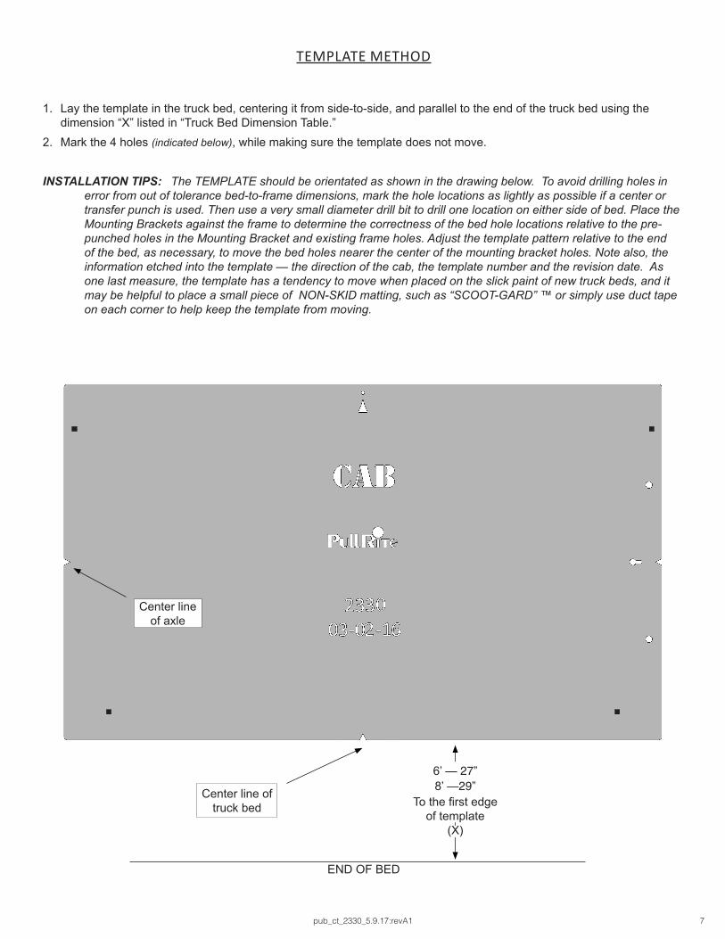
1� Lay the template in the truck bed, centering it from side-to-side, and parallel to the end of the truck bed using the dimension “X” listed in “Truck Bed Dimension Table�”
2� Mark the 4 holes (indicated below), while making sure the template does not move�
INSTALLATION TIPS: The TEMPLATE should be orientated as shown in the drawing below. To avoid drilling holes in error from out of tolerance bed-to-frame dimensions, mark the hole locations as lightly as possible if a center or transfer punch is used. Then use a very small diameter drill bit to drill one location on either side of bed. Place the Mounting Brackets against the frame to determine the correctness of the bed hole locations relative to the pre-punched holes in the Mounting Bracket and existing frame holes. Adjust the template pattern relative to the end of the bed, as necessary, to move the bed holes nearer the center of the mounting bracket holes. Note also, the information etched into the template — the direction of the cab, the template number and the revision date. As one last measure, the template has a tendency to move when placed on the slick paint of new truck beds, and it may be helpful to place a small piece of NON-SKID matting, such as “SCOOT-GARD” ™ or simply use duct tape on each corner to help keep the template from moving.
TEMPLATE METHOD
END OF BED
Center line of truck bed
Center line of axle
6’ — 27”
To the first edge of template
(X)
8’ —29”

pub_ct_2330_5.9.17:revA1 8
INSTALLATION
Since most truck beds are not installed square to the frame or are the same distance from the back of the cab, the in-staller will need to make sure the bed holes line up properly with the center of each mounting bolt hole.
The basic steps in this section are as follows:• Layout the bed holes• Drill the first pilot hole in the bed• Check centering• Adjust the bed hole layout if necessary• Drill the second pilot hole and check centering to ensure bed hole locations are square to the frame; adjust as
needed• Drill remaining pilot holes in the bed; check centering
Detailed Installation Instructions
1. Use transparent tape to cover the mounting post hole on the top of each mounting bracket (when the pilot hole is drilled through the bed, the tape will be pierced by the drill bit; it should be positioned in the center of the mounting post hole).
2. Position the Driver Side Mounting Bracket on the frame and clamp, or fasten in place to determine if your bed layout marks are square to the frame, making sure the bracket is tight against the frame (some mounting brackets may have a slight warp due to the metal characteristics during the welding process).
WARNING: Prior to drilling any holes, be sure to check the inside of the frame to guard against drilling into the fuel tank, wiring, brake lines or fuel modules.
NOTE: Some truck beds are not installed square on their frame by the manufacturer. To ensure your pilot holes are aligned properly, it is important that you use the measurements provided only as a starting point and make adjustments to square the remaining holes to the frame. If you are using the Layout Method, you may accomplish the same thing by using a framing square and straight edge. Once the rear driver side pilot hole is centered, you will use this hole as a point of reference for all remaining pilot hole adjustments. If you are using the Template Method, simply use the properly drilled hole as a pivot.
3. Drill the first 1/8” pilot hole through the truck bed over the forward row where you made the mark during the “Marking Bed for Drilling.”
4. Keep the drill bit in the pilot hole and check that the drilled hole is centered in the cross-sill of the truck frame. If you are using a hand drill, we recommend using a drill guide jig or a block to assure the drill bit is perpendicular to the bed.
5. Repeat Steps 3 and 4 for the remaining mounting post hole pilot holes.
PART 1 — BRACKET PLACEMENT & BED HOLE LOCATIONS
bed cross-sills
Passenger Side view
FRONT

pub_ct_2330_5.9.17:revA1 9
INSTALLATION
PART 2 — FRONT MOUNTING BRACKETS INSTALLATION
1. Locate the pre-existing 5/8” holes found on the driver side (nearest cab), outside truck frame directly below the bed cross-sill (see below).
2. Lift the Driver Side Mounting Bracket {A} into position making sure the 1/2” locator pin on the mounting bracket is placed into the 5/8” locator hole.
3. Center the post holder opening with the cross-sill and pilot hole (if working alone, use a quick clamp to hold bracket in position).
4. Check alignment of the drilled hole and the front post holder location. If the pilot hole is not centered in the cross-sill and bracket, then the pilot hole needs to be relocated. To check bracket, keep the drill bit in the pilot hole and check for centering (front-to-back and left-to-right) in the Mounting Post holder (right).
NOTE: If you need to relocate the pilot hole, you must relocate the other holes that were marked during the “MARKING THE TRUCK BED FOR DRILLING” too, if drill bit is not centered. If the bracket was taped, you can remove bracket to see where the drill bit pierced the tape on the side bracket while drilling the bed holes.
5. Repeat Step 4 for the rear post holder location, checking for proper alignment.
6. Once proper alignment has been checked and repositioned (if needed), remove the Mounting Bracket from the frame.
7. Using a hole saw or step drill, increase the truck bed pilot holes to a minimum of 1-7/8” diameter; both the top of the bed and cross-sill need to be increased (cross-sill drilling shown
right).
8. Reinstall the Mounting Bracket and clamp in place.
pre-existing5/8” locator hole
Driver Side Mounting Bracket (front post holder)
Drilling the cross-sill with Mounting Bracket removed
AMounting Bracket
locator pin (reverse view)
Driver Side Mounting Bracket installation
FRONT

pub_ct_2330_5.9.17:revA1 10
INSTALLATION
PART 2 — MOUNTING BRACKETS INSTALLATION
9. Take a U-Bolt {J} and align it with the front hole and front slot in the side bracket (below).
10. Starting on the inside of the frame, place the U-Bolt on the inside of the frame having the threads pointing outward. Carefully route the U-Bolt around the brake and fuel lines so that it sits on the frame and is not crushing the fuel or brake lines.
11. Thread two Flange Nuts {I} onto the U-bolt. Hand tighten only.
12. Repeat Steps 9-11 for the rear holes of the Mounting Bracket.
13. Repeat all previous steps for the Passenger Side Mounting Bracket.
ADriver Side Mounting Bracket installation
IJ

pub_ct_2330_5.9.17:revA1 11
INSTALLATION
1� Install mounting posts into their respective positions, being certain to install the longer Mounting Posts {E} into the front post holders and the shorter Mounting Posts {F} in the rear post holders of each bracket�
2� Align the roll pin with the notches in the Mounting Post Holder�3� Rotate the post 90° to lock into place (right)�
TORQUE TABLE3/8” bolt — 31 ft. lbs.1/2” bolt — 75 ft. lbs.5/8” bolt — 151 ft. lbs.3/4” bolt — 266 ft. lbs.
U-bolts — 75 ft. lbs.
PART 3 — MOUNTING POST INSTALLATION
PART 4 — FINAL INSTALLATION PROCEDURES
1� Place the Base Rails over the mounting posts� 2� Secure each base rail in place with the supplied Base Rail Release Pins {G} and
Pin Clips {H} (the pins must pass through both the Base Rail and Mounting Post and captured with the Pin Clips)�
3� Remove the Hitch Pins and Pin Clips that are pre-installed on your hitch, and set the hitch on the Base Rails by centering the tabs on the bottom of the hitch into the slots on the Base Rails
4� Install the Hitch Pins through the side of the base rails to secure the hitch assembly to the base rails using the supplied Pin Clips�
5� Make certain the hitch comes on and off without binding prior to completing final torques�6� Tighten all bolts, including the base rail bolts according to the Torque Table specs below�
Installed Mounting Post (rotated 90°)
roll pin
notches

MANUFACTURED BY:PULLIAM ENTERPRISES, INC.
13790 East Jefferson Blvd.Mishawaka, IN 46545
(574) 259-1520 • (800) [email protected] • www.pullrite.com