Documentation Hydraulikaggregat · 2018-04-13 · 5 Ausgabe / Issue 02.2016 Art.Nr. Part. No....
36
- Ersatzteilliste / Spare parts list - Betriebsanleitung / Operation manual - Konformitätserklärung / Declaration of conformity 1 Ausgabe / Issue 01.2017 bestehend aus / consisting of : Hydraulic Pump HY-Air-2 Hydraulikaggregat Dokumentation Documentation
-
Upload
nguyenngoc -
Category
Documents
-
view
214 -
download
0
Transcript of Documentation Hydraulikaggregat · 2018-04-13 · 5 Ausgabe / Issue 02.2016 Art.Nr. Part. No....

- Ersatzteilliste / Spare parts list- Betriebsanleitung / Operation manual- Konformitätserklärung / Declaration of conformity
1 Ausgabe / Issue 01.2017
bestehend aus / consisting of :
Hydraulic Pump
HY-Air-2
Hydraulikaggregat
DokumentationDocumentation
2
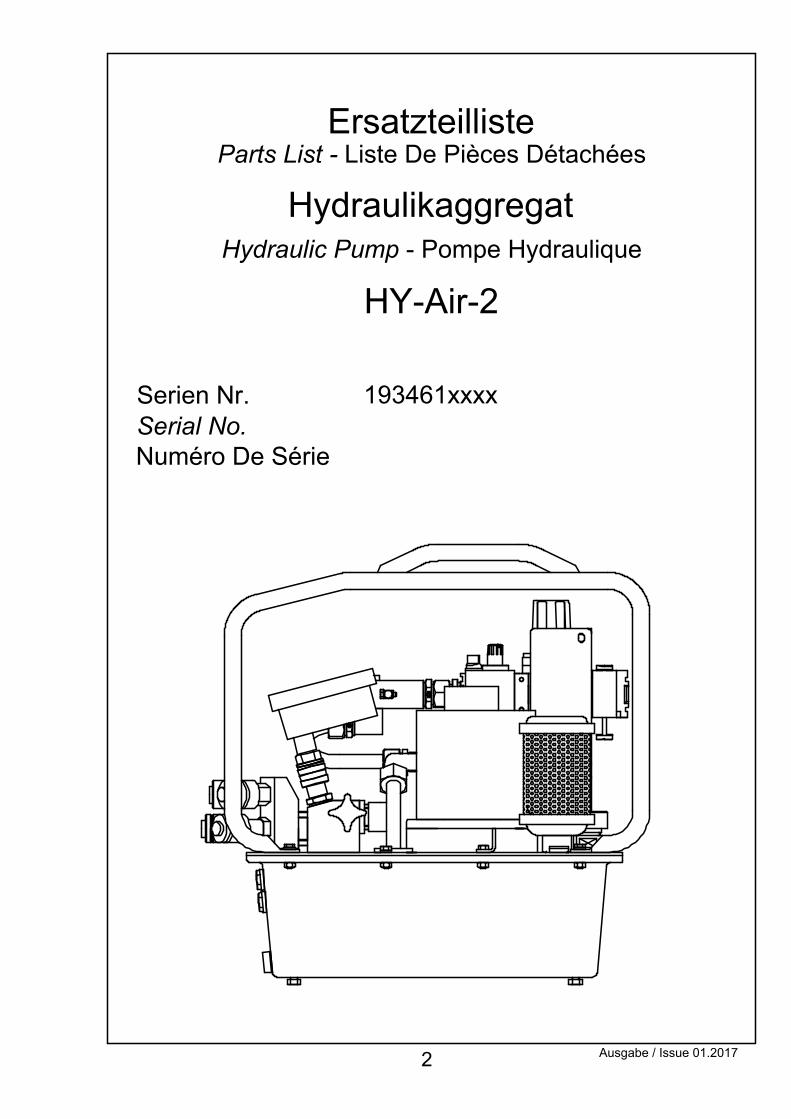
Hydraulic Pump - Pompe HydrauliqueHydraulikaggregat
193461xxxxSerien Nr.Serial No. Numéro De Série
HY-Air-2
Parts List - Liste De Pièces DétachéesErsatzteilliste
Ausgabe / Issue 01.2017
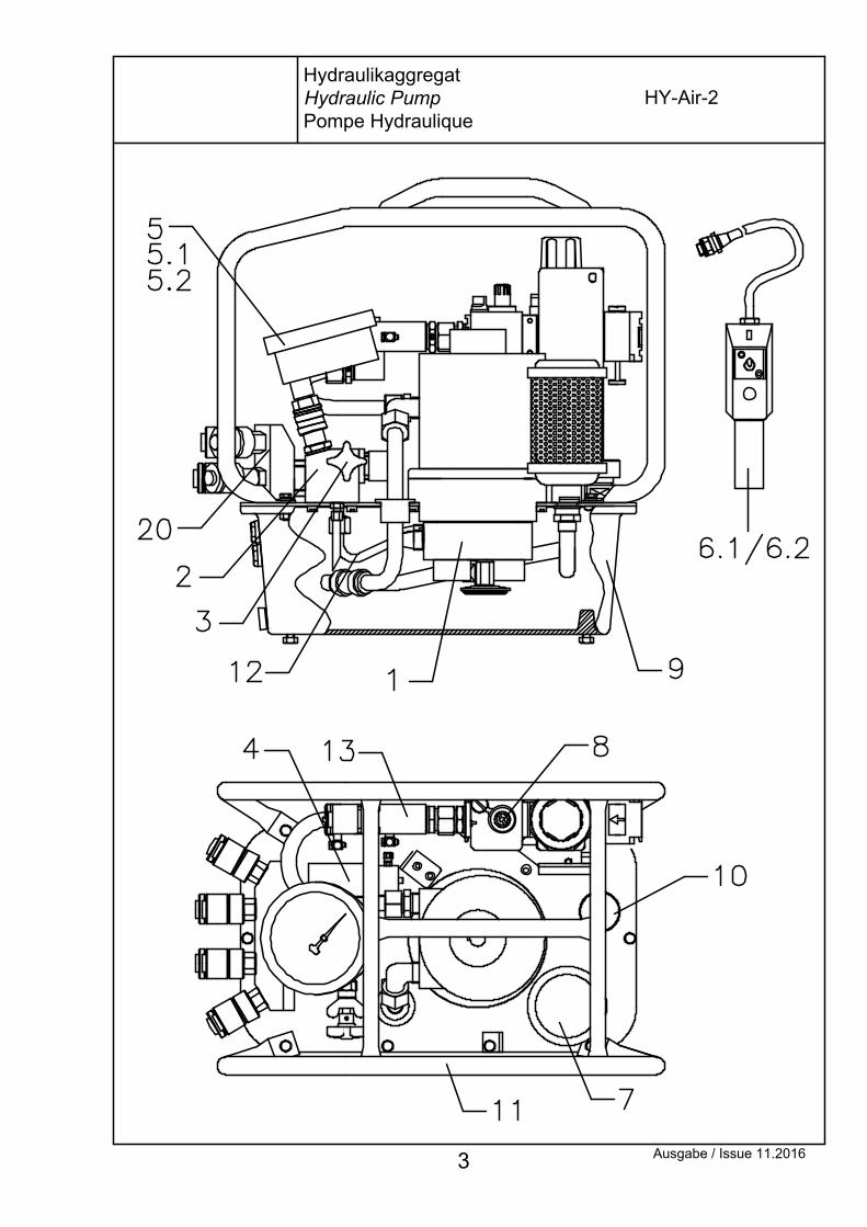
3 Ausgabe / Issue 11.2016
HydraulikaggregatHydraulic PumpPompe Hydraulique
HY-Air-2
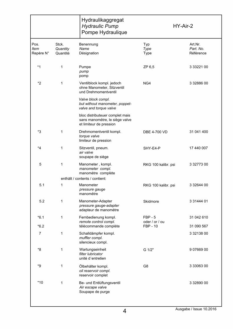
Ölbehälter kompl.oil reservoir compl.reservoir complet
4
*10
Ausgabe / Issue 10.2016
Wartungseinheitfilter lubricatorunité d´entretien
1*9 G8
Schalldämpfer kompl.muffler compl.silencieux compl.
7 1
1*8 G 1/2"
3 33063 00
3 32138 00
9 07669 00
Art.Nr.Part. No.Référence
TypTypeType
Stck.QuantityQuantité
Pos.ItemRepére N°
BenennungNameDésignation
Drehmomentventil kompl.torque valvelimiteur de pression
3 32644 005.1 1 Manometerpressure gauge manomètre
RKG 100 kalibr. psi
Manometer-Adapter pressure gauge-adapter adapteur de manomètre
Fernbedienung kompl.remote control compl.télécommande compléte
1*6.1
*6.2
FBP - 5oder / or / ouFBP - 10
5.2 1 Skidmore
31 042 610
31 090 567
3 31444 01
RKG 100 kalibr. psi5 1 Manometer , kompl.manometer compl.manomètre complète
enthält / contents / contient:
Sitzventil, pneum.air valvesoupape de siège
*4 1 SHY-E4-P
3 32773 00
17 440 007
Be- und EntlüftungsventilAir escape valveSoupape de purge
DBE 4-700 VD
bloc distributeuer complet maissans manomètre, le siège valveet limiteur de pression
*3 1
Valve block compl.but without manometer, poppet-valve and torque valve
31 041 400
Pumpepumppomp
Ventilblock kompl. jedochohne Manometer, Sitzventilund Drehmomentventil
*2 1 NG4
*1 1 ZP 6,5
3 32886 00
3 33221 00
1 3 32890 00
HydraulikaggregatHydraulic PumpPompe Hydraulique
HY-Air-2
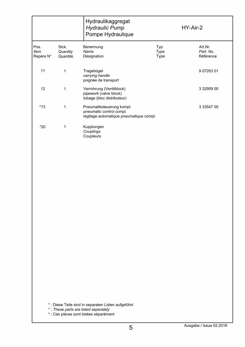
* : Diese Teile sind in separaten Listen aufgeführt* : These parts are listed seperately* : Ces pièces sont listées séparément
Tragebügelcarrying handlepoignée de transport
1 9 07263 01
5 Ausgabe / Issue 02.2016
Art.Nr.Part. No.Référence
TypTypeType
Pos.ItemRepére N°
Stck.QuantityQuantité
BenennungNameDésignation
Pneumatiksteuerung kompl.pneumatic control compl.régtlage automatique pneumatique compl.
KupplungenCouplingsCoupleurs
Verrohrung (Ventilblock)pipework (valve block)tubage (bloc distributeur)
*20 1
1*13
112
11
3 33547 00
3 32909 00
HydraulikaggregatHydraulic PumpPompe Hydraulique
HY-Air-2

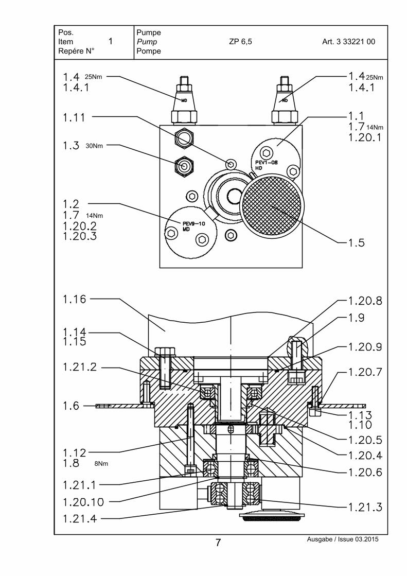
PumpePumpPompe
Pos.ItemRepére N°
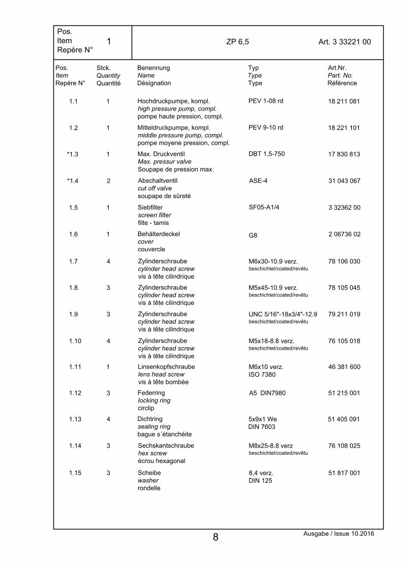
ZP 6,5 Art. 3 33221 00
25Nm
14Nm
30Nm
14Nm
25Nm
8Nm
Ausgabe / Issue 03.2015
1
7
Abschaltventil cut off valvesoupape de sûreté
1.6 1
1.5 1 Siebfilterscreen filterfilte - tamis
Behälterdeckelcovercouvercle
*1.4
*1.3
2
1
1.1 1
Max. DruckventilMax. pressur valveSoupape de pression max.
Hochdruckpumpe, kompl.high pressure pump, compl.pompe haute pression, compl.
SF05-A1/4
2 06736 02
3 32362 00
DBT 1,5-750
PEV 1-08 rd
31 043 067
17 830 813
18 211 081
Pos.ItemRepére N°
Stck.QuantityQuantité
BenennungNameDésignation
TypTypeType
Art.Nr.Part. No.Référence
Pos.ItemRepére N°
1.12 3
1.11
1.9
1
3
1.7
1.10
4
4
1.8 3
Zylinderschraube cylinder head screw vis à tête cilindrique
Linsenkopfschraube lens head screwvis à tête bombèe
Federring locking ring circlip
Zylinderschraube cylinder head screw vis à tête cilindrique
A5 DIN7980
M6x10 verz.ISO 7380
UNC 5/16"-18x3/4"-12.9beschichtet/coated/revêtu
Zylinderschraube cylinder head screw vis à tête cilindrique
Zylinderschraube cylinder head screw vis à tête cilindrique
M6x30-10.9 verz.beschichtet/coated/revêtu
M5x18-8.8 verz.beschichtet/coated/revêtu
M5x45-10.9 verz.beschichtet/coated/revêtu
51 215 001
79 211 019
46 381 600
78 106 030
76 105 018
78 105 045
1.13 Dichtring sealing ring bague s´étanchéite
4 5x9x1 WeDIN 7603
51 405 091
ZP 6,5
1.2 1 Mitteldruckpumpe, kompl.middle pressure pump, compl.pompe moyene pression, compl.
PEV 9-10 rd 18 221 101
ASE-4
1.14
G8
76 108 025
1.15
3 M8x25-8.8 verzbeschichtet/coated/revêtu
Sechskantschraube hex screw écrou hexagonal
Scheibe washer rondelle
3 8,4 verz.DIN 125
51 817 001
Art. 3 33221 00
Ausgabe / Issue 10.2016 8
1

47 002 089
2 05898 00
49 000 621
1.20.7
1.20.5
1.20.1
Simmerringoil sealbague à lèvres
1 Dichtung seal joint
1
2 O-Ringo-ringjoint torique
enthält / contents / contient :
6x1,5-90 NBR
24x32x5 BA
Pos.ItemRepére N°
Stck.QuantityQuantité
BenennungNameDésignation
TypTypeType
Art.Nr.Part. No.Référence
Pos.ItemRepére N°
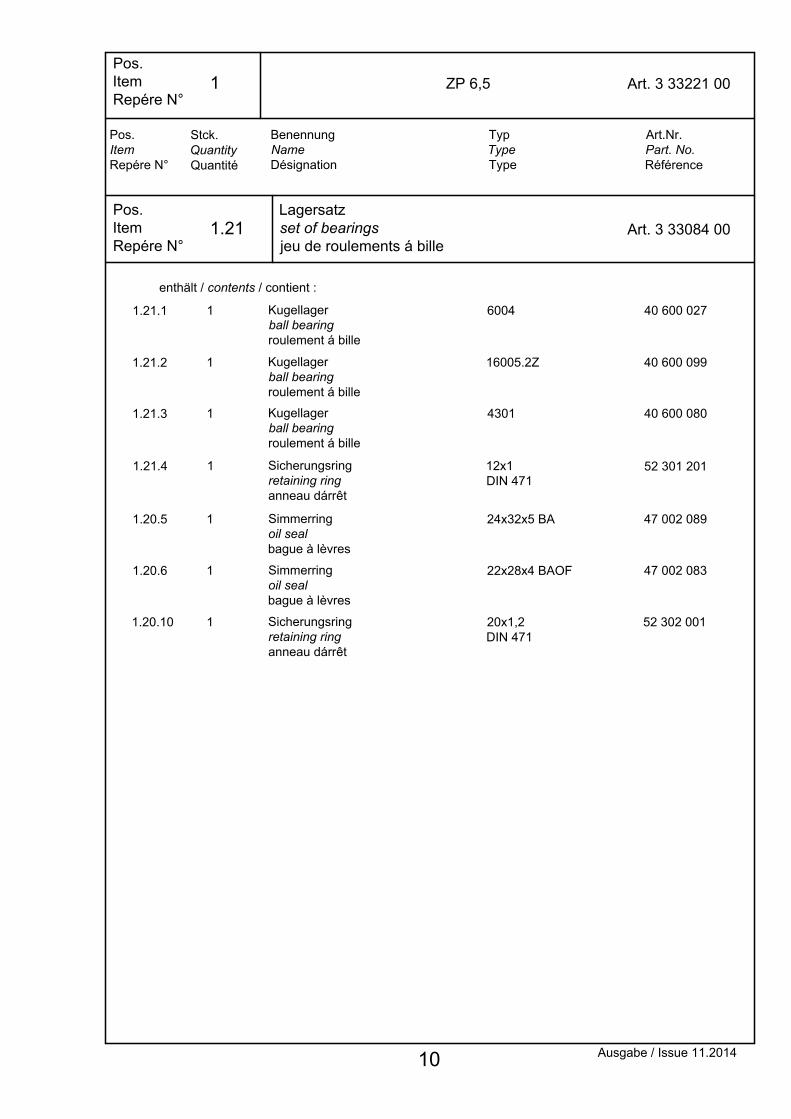
ZP 6,5
O-Ringo-ringjoint torique
1.20.2 1 6,5x1,5-90 NBR 49 000 641
1.20.3 O-Ringo-ringjoint torique
1 8x1,5-90 NBR 49 000 821
1.20.4 O-Ringo-ringjoint torique
1 82x1,5-70 NBR 49 008 214
1.16 1
Simmerringoil sealbague à lèvres
1.20.6 1 22x28x4 BAOF 47 002 083
Pneum.-Motor pneumatic motorpneumatique moto
Typ 6 AM-NRV-7A 3 32422 00
DichtsatzSeal Kit Jeu De Joints
Pos.ItemRepére N°
Art. 3 33065 00
49 004 824O-Ringo-ringjoint torique
11.20.8 48x2-70 NBR
1.20.9 1 O-Ringo-ringjoint torique
68x2-90 NBR 49 006 821
52 302 001Sicherungsring retaining ring anneau dárrêt
1.20.10 1 20x1,2DIN 471
Art. 3 33221 00
Ausgabe / Issue 11.2014 9
1.20
1
52 301 201
40 600 099
40 600 027
Kugellagerball bearingroulement á bille
Kugellagerball bearingroulement á bille
1.21.4
1.21.2
1
1
1.21.1 1
16005.2Z
6004
11.21.3 Kugellagerball bearingroulement á bille
4301 40 600 080
Pos.ItemRepére N°
ZP 6,5
Pos.ItemRepére N°
Lagersatzset of bearingsjeu de roulements á bille
Art. 3 33084 00
enthält / contents / contient :
Art.Nr.Part. No.Référence
Pos.ItemRepére N°
BenennungNameDésignation
Stck.QuantityQuantité
TypTypeType
47 002 08924x32x5 BASimmerringoil sealbague à lèvres
11.20.5
1.20.6 1 Simmerringoil sealbague à lèvres
22x28x4 BAOF 47 002 083
1.20.10 1 Sicherungsring retaining ring anneau dárrêt
20x1,2DIN 471
52 302 001
Art. 3 33221 00
12x1DIN 471
Sicherungsring retaining ring anneau dárrêt
Ausgabe / Issue 11.2014 10
1.21
1

11
1.3Max. DruckventilMax. Pressure ValveSoupape de Pression Max.
Das Ventil ist werkseitig eingestellt.Das Verstellen kann zu Schäden am System bzw.zur Verletzung von Personen führen.Montage und Demontage nur über den Sechskant14 mm möglich.
Sechskant / Hexagon / Clé hexagonale - 14 mmAnzugsmoment / Torque to / Serrage au couple - 30 Nm
This Valve is adjusted by the factory.The manipulation of the adjustment may cause damageof the system and / or personal injure.Assembly or disassembly only possible withHexagon 14 mm.
Cette soupape a èté préreglée en usine.Tout déreglage de cet ajustement peut entrainer unaccident sur le système ou sur un opérateur.Montage et demontage uniquement possible par I'hexagone 14 mm.
Pos.ItemRepére N°
Art. 17 830 813DBT 1,5-750
Ausgabe / Issue 11.2007
Achtung:
Warning:
Attention:

49 001 011
49 001 421
Art.Nr.Part. No.Référence
Art. 31 090 259
enthält / contents / contient :
O-Ring o-ring joint torique
BenennungNameDésignation
Dichtsatz für Abschaltventil kompl.Seal Kit for Cut Off Valve compl.Jeu De Joints Pour Soupape De Sûreté compl.
Pos.ItemRepére N°
Pos.ItemRepére N°
2
1
1
1
O-Ring o-ring joint torique
Stck.QuantityQuantité
10,3x1,2-90NBR
14x1,5-90NBR
TypTypeType
Art. 31 043 067ASE - 4Abschaltventil kompl.Cut Off Valve compl.Soupape De Sûreté Reglable compl.
Pos.ItemRepére N°
Anzugsmoment / Torque to / Serrage au couple - 25 Nm
Sechskant / Hexagon / Clé hexagonale - SW 17
49 001 0213 O-Ring o-ring joint torique
1 10x1,2-90NBR
49 000 7314 O-Ring o-ring joint torique
1 7x1-90NBR
47 003 0315 Stützring ring bague anti-ext.
1 11,2/13x0,7-POM
47 003 0336 1 Stützring ring bague anti-ext.
10,2/12x0,6-POM
Ausgabe / Issue 02.2007 12
1.4.1
1.4

Ventilblock kompl.Valve Block compl.Bloc Distributeur compl.
Pos.ItemRepére N°
Art. 3 32886 00NG4
Ausgabe / Issue 11.2016
Pos. / Item / Repére:mit Schraubensicherung LOXEAL 83.54 eingeklebtpasted into with nut locking LOXEAL 83.54collé avec frein de vis LOXEAL 83.54
Pos. / Item / Repére:Achtung:Montage bzw. Demontage des Ventilsnur über den Sechskant 14 mm möglich.Warning:Assembly or disassembly onlypossible with hexagon 14 mm.Attention: Montage et démontage uniquementpossible par l'hexagon 14 mm.
Pos. / Item / Repére:mit Schraubensicherung LOXEAL 55.03 eingeklebtpasted into with nut locking LOXEAL 55.03collé avec frein de vis LOXEAL 55.03
(20Nm)
(55Nm)
(20Nm)
13
2
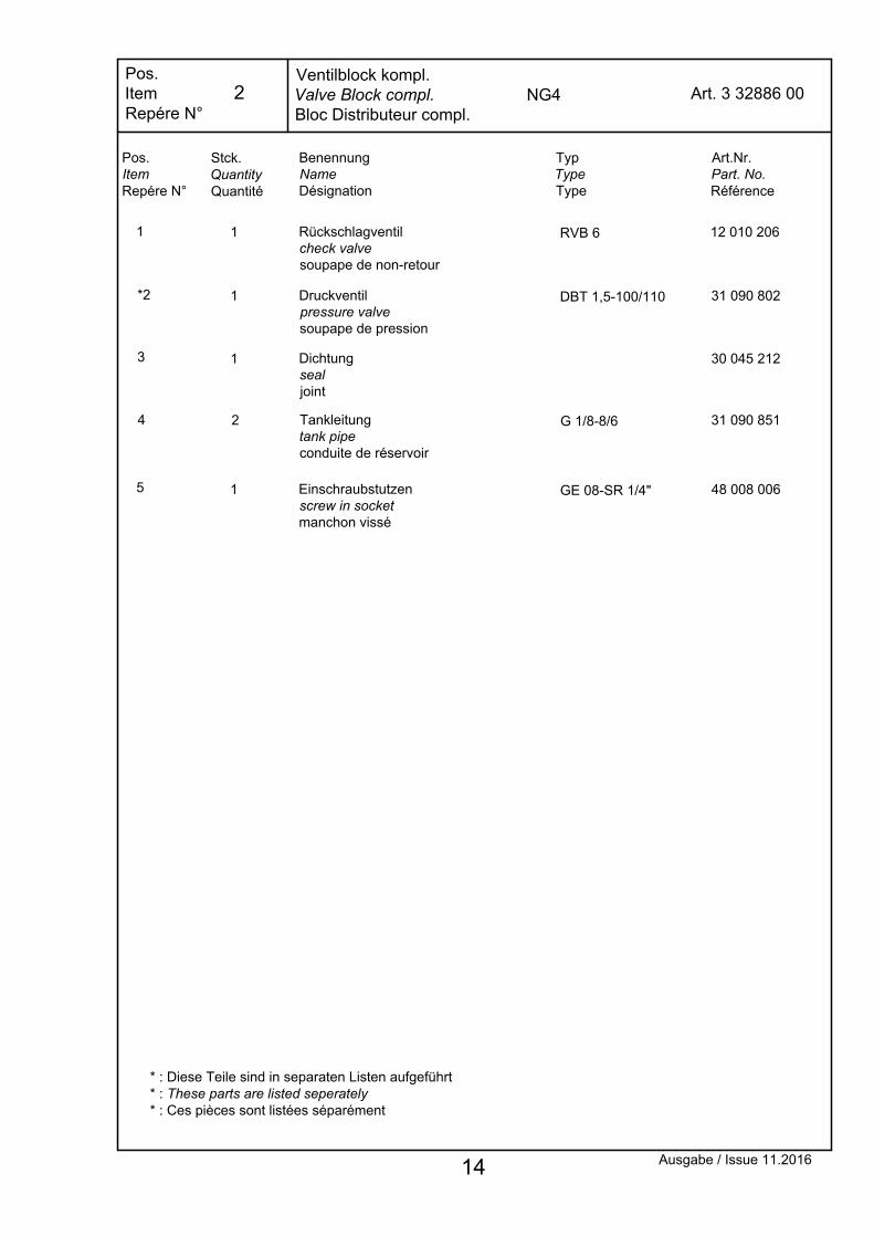
Dichtung sealjoint
Stck.QuantityQuantité
1
1
Pos.ItemRepére N°
1
4
3
BenennungNameDésignation
Druckventil pressure valve soupape de pression
DBT 1,5-100/110
TypTypeType
Art.Nr.Part. No.Référence
31 090 802
30 045 212
*2
12 010 206Rückschlagventil check valve soupape de non-retour
1 RVB 6
Pos.ItemRepére N°
Art. 3 32886 00NG4Ventilblock kompl.Valve Block compl.Bloc Distributeur compl.
Ausgabe / Issue 11.2016
5
Tankleitung tank pipe conduite de réservoir
2 G 1/8-8/6 31 090 851
Einschraubstutzen screw in socket manchon vissé
1 GE 08-SR 1/4" 48 008 006
* : Diese Teile sind in separaten Listen aufgeführt* : These parts are listed seperately* : Ces pièces sont listées séparément
14
2
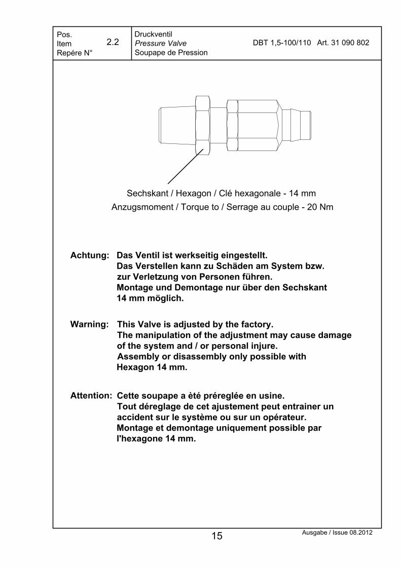
DruckventilPressure ValveSoupape de Pression
Das Ventil ist werkseitig eingestellt.Das Verstellen kann zu Schäden am System bzw.zur Verletzung von Personen führen.Montage und Demontage nur über den Sechskant14 mm möglich.
Sechskant / Hexagon / Clé hexagonale - 14 mmAnzugsmoment / Torque to / Serrage au couple - 20 Nm
This Valve is adjusted by the factory.The manipulation of the adjustment may cause damageof the system and / or personal injure.Assembly or disassembly only possible withHexagon 14 mm.
Cette soupape a èté préreglée en usine.Tout déreglage de cet ajustement peut entrainer unaccident sur le système ou sur un opérateur.Montage et demontage uniquement possible par I'hexagone 14 mm.
Pos.ItemRepére N°
Art. 31 090 802DBT 1,5-100/110
Ausgabe / Issue 08.2012
Achtung:
Warning:
Attention:
15
2.2
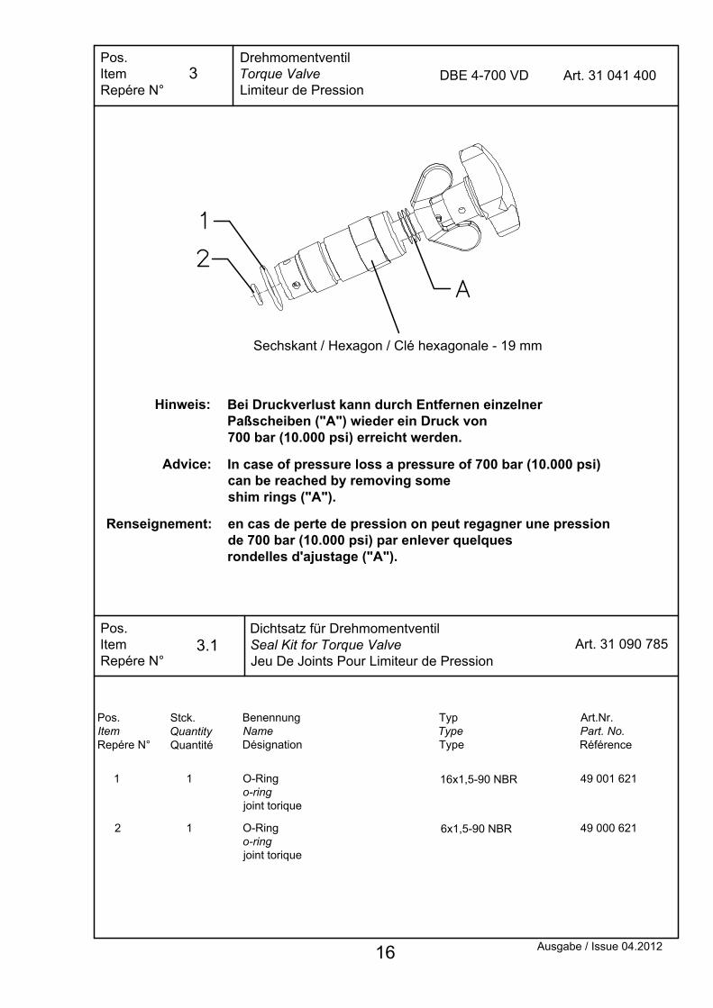
DrehmomentventilTorque ValveLimiteur de Pression
DBE 4-700 VD
Dichtsatz für DrehmomentventilSeal Kit for Torque ValveJeu De Joints Pour Limiteur de Pression
2
1
1
1
O-Ring o-ring joint torique
O-Ring o-ring joint torique
Pos.ItemRepére N°
Pos.ItemRepére N°
Pos.ItemRepére N°
Sechskant / Hexagon / Clé hexagonale - 19 mm
Stck.QuantityQuantité
BenennungNameDésignation
49 001 621
49 000 621
16x1,5-90 NBR
6x1,5-90 NBR
Art.Nr.Part. No.Référence
Art. 31 090 785
Art. 31 041 400
TypTypeType
Ausgabe / Issue 04.2012
Bei Druckverlust kann durch Entfernen einzelner Paßscheiben ("A") wieder ein Druck von 700 bar (10.000 psi) erreicht werden.
Hinweis:
In case of pressure loss a pressure of 700 bar (10.000 psi) can be reached by removing some shim rings ("A").
Advice:
en cas de perte de pression on peut regagner une pression de 700 bar (10.000 psi) par enlever quelques rondelles d'ajustage ("A").
Renseignement:
16
3.1
3

7x1,5-90 NBR
Pos.ItemRepére N°
4.1
BenennungNameDésignation
O-Ring o-ring joint torique
Stck.QuantityQuantité
4
TypTypeType
49 000 721
Art.Nr.Part. No.Référence
Pos.ItemRepére N°
Sitzventilair valveSoupape de Siège
Ausgabe / Issue 01.2009
SHY-E4-P Art. 17 440 007
Dichtsatz für SitztventilSeal Kit for air valveJeu De Joints Pour Soupape de Siège
Pos.ItemRepére N°
Art. 31 091 159
17
4.1
4
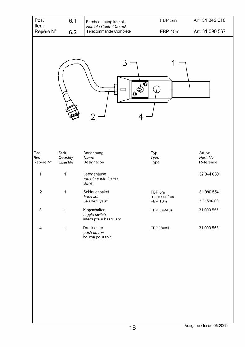
Fernbedienung kompl.Remote Control Compl.Télécommande Compléte
FBP 5m
Drucktaster push buttonbouton poussoir
BenennungNameDésignation
Kippschalter toggle switch interrupteur basculant
Schlauchpaket hose setJeu de tuyaux
13
4 1
Stck.QuantityQuantité
Pos.ItemRepére N°
2
1
1
1 Leergehäuse remote control caseBoîte
FBP Ein/Aus
FBP Ventil
TypTypeType
Pos.ItemRepére N°
FBP 5m
31 090 557
31 090 558
Art.Nr.Part. No.Référence
32 044 030
31 090 554
Art. 31 042 610
Ausgabe / Issue 05.2009
FBP 10m Art. 31 090 567
FBP 10m 3 31506 00oder / or / ou
6.2
6.1
18

19
8 G 1/2" Art. 9 07669 00Pos.ItemRepére N°
Wartungseinheit (kompl. Modul)Filter lubricator (compl. unit)Unité d´entretien (compl. unité)
11.3
11.2
1
1
Pos.ItemRepére N°
11.1 1
Stck.QuantityQuantité
Filter filterfiltre
Filterbehälterfilter tankréservoir de filtre
Ölerbehälter oiler tank réservoir d´huile
BenennungNameDésignation
TypTypeType
Art.Nr.Part. No.Référence
HZE1Z601
HZE1Z600A
HZE1Z660 40 100 093
40 100 092
40 440 140
Ausgabe / Issue 11.2015

Pos.ItemRepére N°
Stck.QuantityQuantité
3
1
2
Pos.ItemRepére N°
49 034 054
Art.Nr.Part. No.Référence
Art. 3 33063 00
40 300 004
Dichtung sealjoint
Ölschauglas oil sight glass jauge de mini/max
2
BenennungNameDésignation
1
GN 541-11G3/8"-A
TypTypeType
Ölbehälter kompl.Oil Reservoir Compl.Réservoir Compl.
G8
4
2 06709 00Befestigungsmutter nut écrou
2 G3/8"-Ms
5
3 33161 00Verschlußschraube plug bouchon
1 3/8"
Ausgabe / Issue 11.2016
1
23
Ø340x5 - 70 NBR
mit Schraubensicherungeingeklebtpasted into with nut lockingcollé avec frein de`vìs(z.B. / i.e. LOXEAL 55.03)
Sechskantschraubehex screwécrou hexagonal
4 M8x16-8.8 verz.ISO 4017
45 017 101
4
56 Nm
20 Nm
20
9
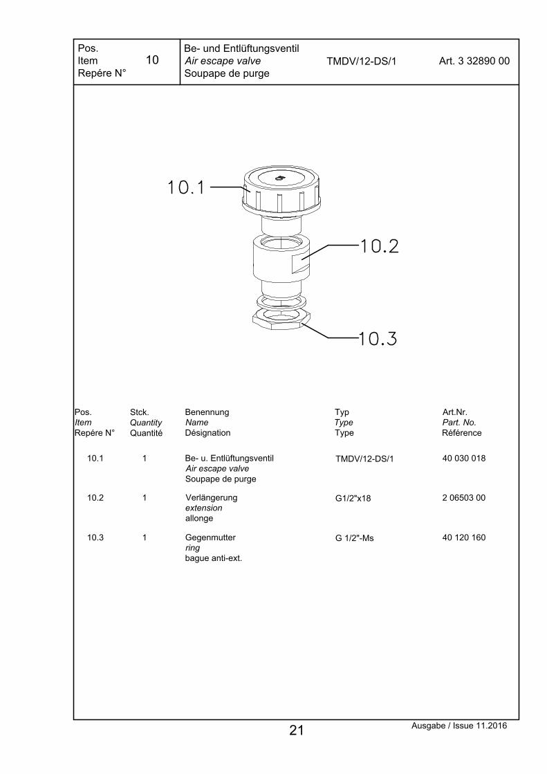
2 06503 00
40 030 018
Art.Nr.Part. No.Référence
Be- u. EntlüftungsventilAir escape valveSoupape de purge
BenennungNameDésignation
Pos.ItemRepére N°
10.2
10.1
1
1
Verlängerungextensionallonge
Stck.QuantityQuantité
G1/2"x18
TMDV/12-DS/1
TypTypeType
Art. 3 32890 00TMDV/12-DS/1Be- und EntlüftungsventilAir escape valveSoupape de purge
Pos.ItemRepére N°
40 120 16010.3 1 Gegenmutterring bague anti-ext.
G 1/2"-Ms
Ausgabe / Issue 11.2016 21
10
22
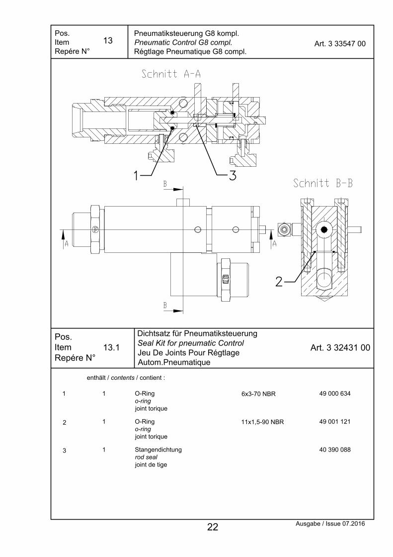
13.1
13Pneumatiksteuerung G8 kompl.Pneumatic Control G8 compl.Régtlage Pneumatique G8 compl.
Art. 3 33547 00Pos.ItemRepére N°
enthält / contents / contient :
2
1 6x3-70 NBR1 O-Ring o-ring joint torique
49 000 634
1 O-Ring o-ring joint torique
49 001 12111x1,5-90 NBR
Ausgabe / Issue 07.2016
Dichtsatz für PneumatiksteuerungSeal Kit for pneumatic ControlJeu De Joints Pour Régtlage Autom.Pneumatique
Pos.ItemRepére N°
Art. 3 32431 00
3 1 Stangendichtung rod seal joint de tige
40 390 088

Pos.ItemRepére N°
KupplungCouplingCoupleur
Wahlweise / alternatively / alternativement :
1
1.1
1.2
Pos.ItemRepére N°
1
1
Stck.QuantityQuantité
1 ST
ST
ST
TypTypeType
Sicherheits-Steckkupplungs-MuffeSafety plug-in female couplingCoupleur femelle enfichable de sûreté
Sicherheits-Steckkupplungs-SteckerSafety plug-in male couplingCoupleur mâle enfichable de sûreté
Kupplungspaarpair of couplings paire de coupleurs
BenennungNameDésignation
16 083 402
16 084 402
10 210 001
Art.Nr.Part. No.Référence
Federspringressort
1.3 2 47 001 265
Air-PumpeAir-pumpAir-pompe
(50Nm)
(50Nm)(50Nm)
Schutzkappe inkl. Verlierschutzcap incl. protection against lossbouchon incl. protection contre la perte
1.4 2 16 089 100
Ausgabe / Issue 07.2016 23
20

Doppelnippeldouble nipplemamelon double
BenennungNameDésignation
Kupplungspaarpair of couplings paire de coupleurs
Pioneer-Schraubkupplungs-SteckerPioneer screw male couplingCoupleur mâle de vis de Pioneer
Pioneer-Schraubkupplungs-MuffePioneer screw female couplingCoupleur femelle de vis de Pioneer
oder / or / ou:
KupplungCouplingCoupleur
3.4 1
3.1
3.2
3
1
1
1
Pos.ItemRepére N°
Stck.QuantityQuantité
Pos.ItemRepére N°
1/4" NPTF
PI
PI
PI
Ausgabe / Issue 07.2016
9 07394 00
40 230 009
10 210 003
40 230 010
TypTypeType
Art.Nr.Part. No.Référence
Federspringressort
3.3 2 47 001 265
Air-PumpeAir-pumpAir-pompe
Schutzstecker inkl. Verlierschutzcap incl. protection against lossbouchon incl. protection contre la perte
2.5 1 716 16 067 100
Schutzkappe inkl. Verlierschutzcap incl. protection against lossbouchon incl. protection contre la perte
2.4 1 716 16 068 100
2.2 1
2
2.1 1
1 SI
SI
SI
Sicherheits-Schraubkupplungs-SteckerSafety screw male couplingCoupleur mâle de vis de sûreté
Sicherheits-Schraubkupplungs-MuffeSafety screw female couplingCoupleur femelle de vis de sûreté
Kupplungspaarpair of couplings paire de coupleurs
16 064 102
10 210 002
16 063 102
Federspringressort
2.3 2 47 001 265
oder / or / ou:
Schutzstecker inkl. Verlierschutzcap incl. protection against lossbouchon incl. protection contre la perte
2.5 1 716 16 067 100
Schutzkappe inkl. Verlierschutzcap incl. protection against lossbouchon incl. protection contre la perte
2.4 1 716 16 068 100
24
20
Pos.ItemRepére N°
Pos.ItemRepére N°
Art.Nr.Part. No.Référence
BenennungNameDésignation
TypTypeType
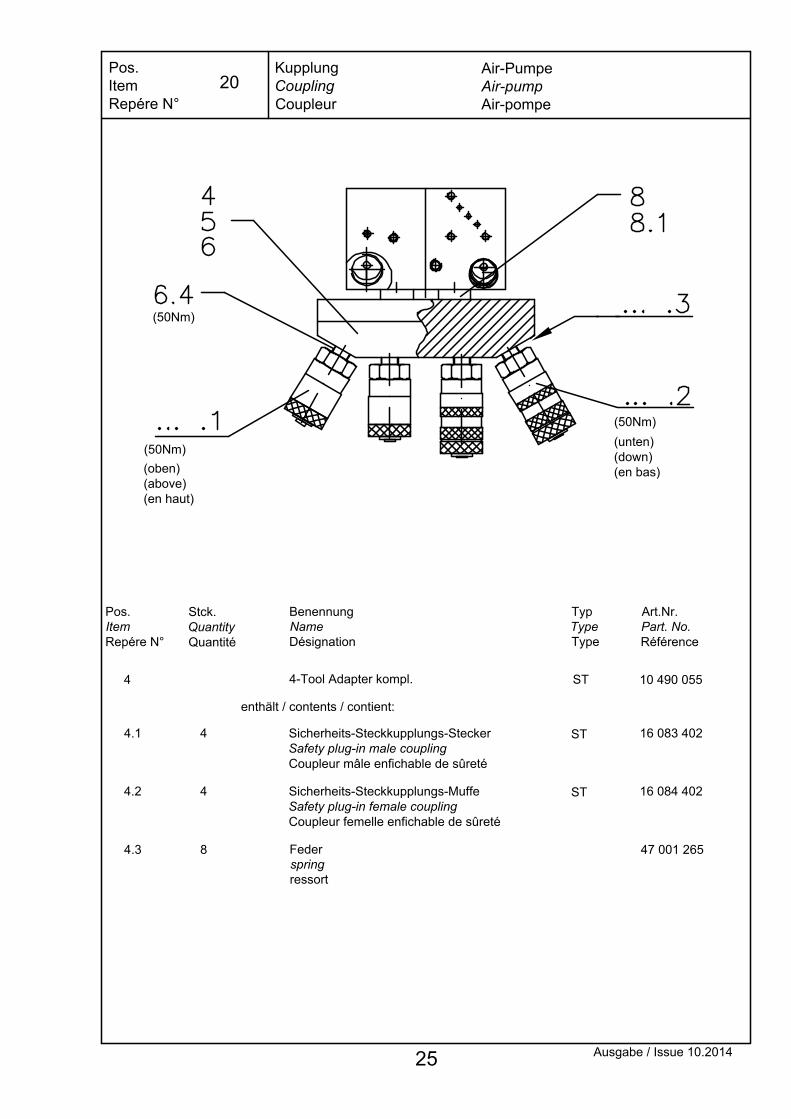
KupplungCouplingCoupleur
4-Tool Adapter kompl.4 10 490 055ST
Sicherheits-Steckkupplungs-SteckerSafety plug-in male couplingCoupleur mâle enfichable de sûreté
Sicherheits-Steckkupplungs-MuffeSafety plug-in female couplingCoupleur femelle enfichable de sûreté
4.2
4.1
16 084 402ST
ST 16 083 402
enthält / contents / contient:
Stck.QuantityQuantité
4
4
(oben)(above)(en haut)
(unten)(down)(en bas)
Ausgabe / Issue 10.2014
4.3 8 Federspringressort
47 001 265
Air-PumpeAir-pumpAir-pompe
(50Nm)
(50Nm)
(50Nm)
25
20
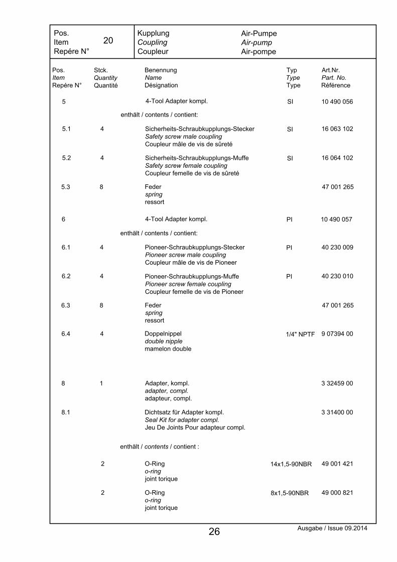
5 10 490 056
10 490 057PI
SI4-Tool Adapter kompl.
4-Tool Adapter kompl.
Pioneer-Schraubkupplungs-MuffePioneer screw female couplingCoupleur femelle de vis de Pioneer
Pioneer-Schraubkupplungs-SteckerPioneer screw male couplingCoupleur mâle de vis de Pioneer
Sicherheits-Schraubkupplungs-MuffeSafety screw female couplingCoupleur femelle de vis de sûreté
Sicherheits-Schraubkupplungs-SteckerSafety screw male couplingCoupleur mâle de vis de sûreté
6.2
6.1
5.1
5.2
PI
PI
SI
SI
40 230 009
40 230 010
16 063 102
16 064 102
enthält / contents / contient:
enthält / contents / contient:
4
4
4
4
Doppelnippeldouble nipplemamelon double
6.4 4 1/4" NPTF 9 07394 00
KupplungCouplingCoupleur
Pos.ItemRepére N°
Ausgabe / Issue 09.2014
Pos.ItemRepére N°
Stck.QuantityQuantité
BenennungNameDésignation
TypTypeType
Art.Nr.Part. No.Référence
enthält / contents / contient :
2
8
2
1
O-Ring o-ring joint torique
O-Ring o-ring joint torique
Adapter, kompl.adapter, compl.adapteur, compl.
8x1,5-90NBR 49 000 821
14x1,5-90NBR 49 001 421
3 32459 00
Dichtsatz für Adapter kompl.Seal Kit for adapter compl.Jeu De Joints Pour adapteur compl.
8.1 3 31400 00
6
5.3 8 Federspringressort
47 001 265
6.3 8 Federspringressort
47 001 265
Air-PumpeAir-pumpAir-pompe
26
20
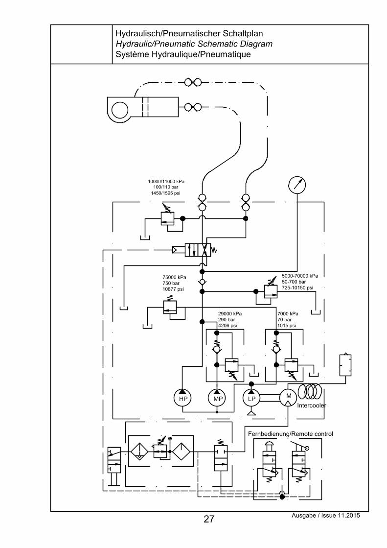
LPHP M
Fernbedienung/Remote control
Intercooler
75000 kPa750 bar10877 psi
5000-70000 kPa50-700 bar725-10150 psi
7000 kPa70 bar1015 psi
MP
29000 kPa290 bar4206 psi
10000/11000 kPa100/110 bar
1450/1595 psi
Ausgabe / Issue 11.2015 27
Hydraulisch/Pneumatischer SchaltplanHydraulic/Pneumatic Schematic DiagramSystème Hydraulique/Pneumatique
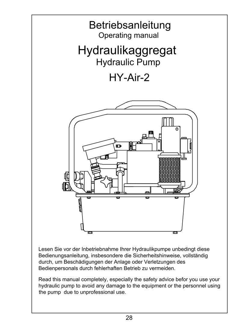
Read this manual completely, especially the safety advice befor you use your hydraulic pump to avoid any damage to the equipment or the personnel using the pump due to unprofessional use.
Lesen Sie vor der Inbetriebnahme Ihrer Hydraulikpumpe unbedingt diese Bedienungsanleitung, insbesondere die Sicherheitshinweise, vollständig durch, um Beschädigungen der Anlage oder Verletzungen des Bedienpersonals durch fehlerhaften Betrieb zu vermeiden.
Hydraulikaggregat
HY-Air-2Hydraulic Pump
BetriebsanleitungOperating manual
28
HydraulikaggregatHydraulic Pump
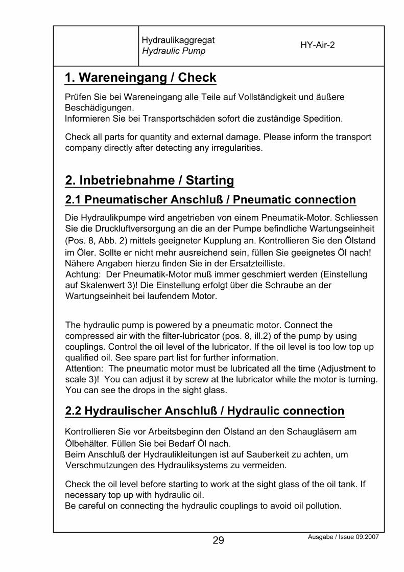
The hydraulic pump is powered by a pneumatic motor. Connect the compressed air with the filter-lubricator (pos. 8, ill.2) of the pump by using couplings. Control the oil level of the lubricator. If the oil level is too low top up qualified oil. See spare part list for further information.Attention: The pneumatic motor must be lubricated all the time (Adjustment to scale 3)! You can adjust it by screw at the lubricator while the motor is turning. You can see the drops in the sight glass.
Check the oil level before starting to work at the sight glass of the oil tank. If necessary top up with hydraulic oil.Be careful on connecting the hydraulic couplings to avoid oil pollution.
Kontrollieren Sie vor Arbeitsbeginn den Ölstand an den Schaugläsern am Ölbehälter. Füllen Sie bei Bedarf Öl nach.Beim Anschluß der Hydraulikleitungen ist auf Sauberkeit zu achten, um Verschmutzungen des Hydrauliksystems zu vermeiden.
2.2 Hydraulischer Anschluß / Hydraulic connection
1. Wareneingang / Check
Die Hydraulikpumpe wird angetrieben von einem Pneumatik-Motor. Schliessen Sie die Druckluftversorgung an die an der Pumpe befindliche Wartungseinheit (Pos. 8, Abb. 2) mittels geeigneter Kupplung an. Kontrollieren Sie den Ölstand im Öler. Sollte er nicht mehr ausreichend sein, füllen Sie geeignetes Öl nach! Nähere Angaben hierzu finden Sie in der Ersatzteilliste.Achtung: Der Pneumatik-Motor muß immer geschmiert werden (Einstellung auf Skalenwert 3)! Die Einstellung erfolgt über die Schraube an der Wartungseinheit bei laufendem Motor.
2.1 Pneumatischer Anschluß / Pneumatic connection2. Inbetriebnahme / Starting
Check all parts for quantity and external damage. Please inform the transport company directly after detecting any irregularities.
Prüfen Sie bei Wareneingang alle Teile auf Vollständigkeit und äußere Beschädigungen.Informieren Sie bei Transportschäden sofort die zuständige Spedition.
Ausgabe / Issue 09.2007 29
HY-Air-2

By switching the toggle switch pos.1 of the remote control (Abb. 1) the pneumatic motor starts and the mounted tool retracts. By pressing the button pos.2 the tool advances, let the button go and it retracts again. You can adjust the necessary pressure at the relief valve pos.3 (Abb.2).To relieve hydraulic pressure, switch toggle pos.1 and press button pos.2.
Ausgabe / Issue 07.2012 30
Abb.1
Beim Umlegen des Kippschalters Pos. 1 an der Fernbedienung (Abb.1) läuft der Pneumatikmotor an und das angeschlossene Werkzeug geht in den Rückhub. Durch drücken des Knopfes 2 schaltet das Werkzeug in den Vorhub, beim Loslassen desselben wieder in den Rückhub. Am Druckeinstellventil Pos.3 (Abb.2) kann der benötigte Druck eingestellt werden.Um den hydraulischen Druck abzubauen Kippschalter Pos.1 umlegen und den Knopf Pos.2 drücken.
2.5 Funktion / Function
Nach Herstellen des pneumatischen Anschlusses und Verbindung der Hydraulikleitungen kann die Pumpe in Betrieb genommen werden.
As soon as the pneumatic connection is provided for and the hoses are connected the pump can be operated.
Sometimes an evacuation of the system is necessary. For this purpose connect a hose to the pump and out both ends together. After this advance and retract the pump several times.
Eventuell ist eine Entlüftung der Pumpe notwendig. Schliessen Sie hierfür einen Hydraulikschlauch an und verbinden Sie die beiden Enden miteinander. Schalten Sie anschließend die Pumpe mehrmals hin und her.
2.4 Betrieb / Operation
HY-Air-2HydraulikaggregatHydraulic Pump
2.3 Entlüften / Air evacuation

Abb.2
Ausgabe / Issue 12.2013 31
HydraulikaggregatHydraulic Pump HY-Air-2
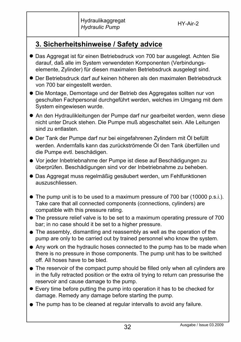
The assembly, dismantling and reassembly as well as the operation of the pump are only to be carried out by trained personnel who know the system.
Every time before putting the pump into operation it has to be checked for damage. Remedy any damage before starting the pump.
Ausgabe / Issue 03.2009
The pump has to be cleaned at regular intervalls to avoid any failure.
The reservoir of the compact pump should be filled only when all cylinders are in the fully retracted position or the extra oil trying to return can pressurise the reservoir and cause damage to the pump.
Any work on the hydraulic hoses connected to the pump has to be made when there is no pressure in those components. The pump unit has to be switched off. All hoses have to be bled.
32
Der Tank der Pumpe darf nur bei eingefahrenen Zylindern mit Öl befüllt werden. Andernfalls kann das zurückströmende Öl den Tank überfüllen und die Pumpe evtl. beschädigen.
The pressure relief valve is to be set to a maximum operating pressure of 700 bar; in no case should it be set to a higher pressure.
The pump unit is to be used to a maximum pressure of 700 bar (10000 p.s.i.). Take care that all connected components (connections, cylinders) are compatible with this pressure rating.
Das Aggregat muss regelmäßig gesäubert werden, um Fehlfunktionen auszuschliessen.
Vor jeder Inbetriebnahme der Pumpe ist diese auf Beschädigungen zu überprüfen. Beschädigungen sind vor der Inbetriebnahme zu beheben.
Die Montage, Demontage und der Betrieb des Aggregates sollten nur von geschulten Fachpersonal durchgeführt werden, welches im Umgang mit dem System eingewiesen wurde.
An den Hydraulikleitungen der Pumpe darf nur gearbeitet werden, wenn diese nicht unter Druck stehen. Die Pumpe muß abgeschaltet sein. Alle Leitungen sind zu entlasten.
Der Betriebsdruck darf auf keinen höheren als den maximalen Betriebsdruck von 700 bar eingestellt werden.
Das Aggregat ist für einen Betriebsdruck von 700 bar ausgelegt. Achten Sie darauf, daß alle im System verwendeten Komponenten (Verbindungs-elemente, Zylinder) für diesen maximalen Betriebsdruck ausgelegt sind.
HY-Air-2HydraulikaggregatHydraulic Pump
3. Sicherheitshinweise / Safety advice

Ausgabe / Issue 01.2017 33
Technische Daten:
Max. Hydraulikdruck : 700 bar/10.000 psiMax hydraulic pressure :
Max. Oberflächentemperatur : 90°C/194°FMax. surface temp. :
Die max. Oberflächentemperatur basiert auf der Erwärmung des Öls.The maximum surface temperature is caused by the heated oil.
Weitere Daten siehe separates Datenblatt.For further information see separate data sheet.
Hersteller: HYTORC-TechnologiesManufacturer: Kleinbeckstraße 3-17 45549 Sprockhövel (Germany)
The Ex-proof hydraulic torque controlled bolting system is in conformity with the EU-Directive 94/9/EG (ATEX100a) as amended 23.March 1994 and is classified to:Klasse: Ex II 2 G Ex c IIB T4.
Die HYTORC, Exgeschützte hydraulische Drehmomentgesteuerte Verschraubungsanlage entspricht den Anforderungen der EU-Richtlinie 94/9EG (ATEX100a) und ist charakterisiert in derKlasse: Ex II 2 G Ex c IIB T4 .
HydraulikaggregatHydraulic Pump HY-Air-2
Ausgabe / Issue 09.2007 34
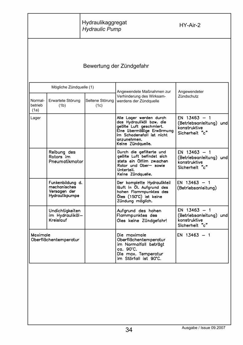
Erwartete Störung (1b)
Seltene Störung (1c)
Angewendete Maßnahmen zurVerhinderung des Wirksam-werdens der ZündquelleNormal-
betrieb (1a)
Lager
Mögliche Zündquelle (1)AngewendeterZündschutz
Bewertung der Zündgefahr
HY-Air-2HydraulikaggregatHydraulic Pump

Issue 09.2007
Expected fault (1b)
Rare disorder (1c)
Normal operation (1a)
Applied measures for the prevention of effect of the ignition source
Bearing
Ignition hazard assessment
Possible ignition source (1)Applied ignition proof
HydraulikaggregatHydraulic Pump
HY-Air-2
35