Doc #: MagAOX-001 MagAO-X Preliminary Design 5.1 Optics ...
18
MagAO-X Preliminary Design 5.1 Optics Specifications Doc #: MagAOX-001 Date: 2017–04–19 Status: Rev. 0.0 Page: 1 of 18 5.1 Optics Specifications Jared R. Males 1 Introduction This document describes the specifications for the optical components of MagAO-X, including surface quality and coatings. We include our knowledge of the existing telescope optics, and the expected performance of the wavefront control systems. In this analysis we assume polished optics follow a von K` arm` an-like PSD of the following form P ( ~ k)= β (1/L 0 ) 2 + ~ k 2 α/2 e -(| ~ k|l 0 ) 2 + β sr . (1) where ~ k is the spatial frequency, β is a normalization constant, α is the PSD index, L 0 is an outer scale (low frequency flattening), and l 0 is the inner scale (high frequency roll-off), and β sr is the surface roughness (the floor reached at high spatial frequency). See Appendix A for a detailed justification of this model using representative PSDs, as well as the methods we use to project the PSDs of various optics onto the primary mirror. The wavefront error (WFE) analysis presented here does not take into account diffraction, rather our goal is to quickly compare trades in the various possible specifications. See the Fresnel model of the system for a diffraction- based analysis. 2 Requirements This analysis is concerned primarily with the static and non-common path (NCP) wavefront errors (WFEs). These sources of WFE affect the Strehl ratio and the contrast. The requirements on the optical surface quality are derived from the high-level science requirements, in conjunction with the performance simulations and error budget. They are • Requirement: Static/NCP WFE < 45 nm rms. At Hα this multiplies Strehl ratio by 0.83. This specification ensures that the bright star Strehl ratio requirement of 70% can be met. • Goal: Static/NCP WFE < 35 nm rms. Strehl ratio (S ) due to static/NCP impacts exposure time as t∝S 3 . Hence we should seek maximum possible performance. • Requirement: Static/NCP WFE contribution to contrast should be < 1 × 10 -3 from 0 to 24 λ/D. This is after the effects of low-order WFS (LOWFS) and/or focal-plane WFS (FPWFS) are taken into account. All of these requirements are derived for the science channel. The WFS channel requirement is simply that it should not be worse, as it has fewer optics. 1
Transcript of Doc #: MagAOX-001 MagAO-X Preliminary Design 5.1 Optics ...

MagAO-X Preliminary Design5.1 Optics Specifications
Doc #: MagAOX-001Date: 2017–04–19Status: Rev. 0.0Page: 1 of 18
5.1 Optics Specifications
Jared R. Males
1 Introduction
This document describes the specifications for the optical components of MagAO-X, including surface qualityand coatings. We include our knowledge of the existing telescope optics, and the expected performance of thewavefront control systems.
In this analysis we assume polished optics follow a von Karman-like PSD of the following form
P(~k) = β((1/L0)2 +
∣∣∣~k∣∣∣2)α/2 e−(|~k|l0)2 + βsr. (1)
where ~k is the spatial frequency, β is a normalization constant, α is the PSD index, L0 is an outer scale (lowfrequency flattening), and l0 is the inner scale (high frequency roll-off), and βsr is the surface roughness (the floorreached at high spatial frequency). See Appendix A for a detailed justification of this model using representativePSDs, as well as the methods we use to project the PSDs of various optics onto the primary mirror.
The wavefront error (WFE) analysis presented here does not take into account diffraction, rather our goal is toquickly compare trades in the various possible specifications. See the Fresnel model of the system for a diffraction-based analysis.
2 Requirements
This analysis is concerned primarily with the static and non-common path (NCP) wavefront errors (WFEs).These sources of WFE affect the Strehl ratio and the contrast. The requirements on the optical surface qualityare derived from the high-level science requirements, in conjunction with the performance simulations and errorbudget. They are
• Requirement: Static/NCP WFE < 45 nm rms. At Hα this multiplies Strehl ratio by 0.83. This specificationensures that the bright star Strehl ratio requirement of 70% can be met.
• Goal: Static/NCP WFE < 35 nm rms. Strehl ratio (S) due to static/NCP impacts exposure time as t∝S3.Hence we should seek maximum possible performance.
• Requirement: Static/NCP WFE contribution to contrast should be < 1 × 10⁻³ from 0 to 24 λ/D. This isafter the effects of low-order WFS (LOWFS) and/or focal-plane WFS (FPWFS) are taken into account.
All of these requirements are derived for the science channel. The WFS channel requirement is simply that itshould not be worse, as it has fewer optics.
1

MagAO-X Preliminary Design5.1 Optics Specifications
Doc #: MagAOX-001Date: 2017–04–19Status: Rev. 0.0Page: 2 of 18
3 The Clay Telescope
MagAO-X is designed for the 6.5 m Magellan Clay telescope. Here we present analysis of the primary mirror(M1), the f/11 fixed secondary (M2), and the tertiary mirror (M3).
3.1 M1: The Magellan Clay primary mirror was cast and polished at the Steward Observatory Mirror Lab(SOML). The post-polishing test data were analyzed (see Appendix B). The surface map is shown in Figure 1. Thesurface height has 12.52 nm rms across all spatial frequencies sampled by the map. Figure 2 shows the surface mapwith 29% central obscuration (defined by the secondary baffle) and with the outer edged masked by 4.4% to maskthe jagged edge. This also has a 12.52 nm rms, only negligibly reduced from the unmasked map.
−3
−2
−1
0
1
2
3
−3 −2 −1 0 1 2 3
y[m
]
x [m]
−60
−40
−20
0
20
40
60
Surf
ace
Hei
ght[
nm]
Figure 1: M1 surface unmasked
Using the un-masked surface map we calculated the 2D PSD of the masked surface. An annular Hann windowwas applied before the FFT, and the resultant PSD was renormalized to have total variance corresponding to 12.52nm rms. Figure 3 shows the median radial profile of the PSD. The best fit (in log space) has slope α = −2.8, avery steep power law.
See Appendix B for additional analysis of the M1 surface.
3.2 Pupil Definition : The Magellan Clay telescope secondary mirror baffle forms a 29% central obscuration.The secondary is supported by 4 supports, called vane ends at Magellan, a.k.a. spiders. Using a 3D model of thetelescope (provided by Charlie Hull), we found the spiders to be offset by 0.34 m from the center, and running at45o. The vane end struts are nominally 0.75” wide. On two of them the MagAO cable-trays, used to route powerand cooling to the ASM, increase the width to 1.5”. These are thin relative to other observatories (e.g. Subaru isreported to have 20 cm wide spiders).
For analysis and simulations pupil masks were made informed by the above specifications. Two masks were
2

MagAO-X Preliminary Design5.1 Optics Specifications
Doc #: MagAOX-001Date: 2017–04–19Status: Rev. 0.0Page: 3 of 18
−3
−2
−1
0
1
2
3
−3 −2 −1 0 1 2 3
y[m
]
x [m]
−60
−40
−20
0
20
40
60
Surf
ace
Hei
ght[
nm]
Figure 2: M1 surface masked with a 95.6% outer radius and 29% central obscuration.
10−610−510−410−310−210−1100101102103
0.01 0.1 1 10 100
Pow
erD
ensi
ty[n
m2
m2]
Spatial Frequency [m−1]
Median profileFit α = −2.8
Figure 3: Median radial profile of the PSD of M1 surface.
made:
1. Input Pupil. This is 6.5m wide, with a 29% central obscuration. Grayscale is used for the spiders to accountfor their width relative to the pixel scale in the mask (calculated by re-binning larger arrays). This is used asthe input for end-to-end simulations, etc.
3

MagAO-X Preliminary Design5.1 Optics Specifications
Doc #: MagAOX-001Date: 2017–04–19Status: Rev. 0.0Page: 4 of 18
2. Coronagraph Pupil. This mask is intended for use in the coronagraph arm. The goal of this mask is tooversize the various features (undersize the pupil overall) to ensure that coronagraph designs are feasibleand alignment tolerances can be met. The outer diameter is undersized to 95.6% (6.21 m projected) to maskout the rough outer edge identified above. The central obscuration is oversized to 31% of the undersizeddiameter, which corresponds to 1/2 an actuator projected onto the high-order (MEMS) DM. The spidermasks are binary and oversized to 68 mm. For scale, this corresponds to a 0.3o tolerance in the pupil rotationalignment.
Figure 4: Defining the MagAO-X pupil. Left: solid model of the telescope showing. Middle: input pupil mask. Right:coronagraph channel mask.
3.3 M2: A post-fabrication measurement of the surface structure function of the Clay f/11 static secondary isshown in Figure 5. We fit this to a power law with index α − 2, where α is the index of the spatial PSD as inEquation (1) (Noll, 1976). The measurements indicate that the surface of M2 has 12.7 nm rms.
0
5
10
15
20
25
30
0 0.2 0.4 0.6 0.8 1 1.2 1.4
rms
[nm
]
distance [m]
DataFit α− 2 = 0.11
Figure 5: Measured structure function of the static f/11 (M2) and our power-law fit.
4

MagAO-X Preliminary Design5.1 Optics Specifications
Doc #: MagAOX-001Date: 2017–04–19Status: Rev. 0.0Page: 5 of 18
3.4 M3: From the manufacturer’s test report for the (now re-coated) tertiary mirror, we have the surface mapshown in Figure 6. We analyzed this map using the same procedure as for M1, and found the PSD shown in Figure7. M3 has a reported surface finish of 13.8 nm rms, with a best fit PSD having α = 3.28.
−0.4
−0.2
0
0.2
0.4
−0.4 −0.2 0 0.2 0.4
y[m
]
x [m]
−30
−20
−10
0
10
20
30
Surf
ace
Hei
ght[
nm]
Figure 6: M3 surface.
10−6
10−5
10−4
10−3
10−2
10−1
100101102
1 10 100
Pow
erD
ensi
ty[n
m2
m2]
Spatial Frequency [m−1]
Median profileFit α = −3.28
Figure 7: M3 PSD from a circular aperture.
5

MagAO-X Preliminary Design5.1 Optics Specifications
Doc #: MagAOX-001Date: 2017–04–19Status: Rev. 0.0Page: 6 of 18
4 Deformable Mirrors
Here we describe the specifications of the deformable mirrors we will use for wavefront correction. For thisanalysis, in all cases we assume that the flat surface quality is perfect within the device’s spatial control bandwidth,so the given surface quality is for the remaining higher spatial frequencies. We assume a PSD with α = 2 for thesesurfaces.
4.1 High Order DM: The high order DM, or tweeter, is a Boston Micromachines Corp. MEMS 2k. This is a2048 actuator device, with 50 actuators across a circular aperture. BMC has guaranteed a 100% yield device withinthe clear aperture described by pupil (allowing for a limited number of bad actuators under a spider). The mainoptical characteristics are summarized in Table 1.
The nominal device we have specified is a 1.5 µm P-V stroke DM. BMC has begun working to determine ifthey have a 3.5 µm stroke 2k DM already fabricated which meets our yield needs. If they do, we have the optionof taking this device. In this case, all other specifications (other than stroke) remain the same. Actuator strokerequirements are addressed in the simulation section.
Table 1: Boston Micromachines 2k Specifications.
Total Linear Pitch CA Flat surface [nm rms]Act. Act. [mm] mm Max Spec Typical
Value: 2048 50 0.4 19.7 20 13
4.2 Low Order DM: We plan to use the Alpao DM97-15 for our low order DMs. We have designed in twoof these. The first serves as the woofer to minimize the stroke requirements on the BMC 2k tweeter. The secondwill be used in the science channel (after the HOWFS beamsplitter), under control by the LOWFS. This allows forcorrection of non-common path errors sensed by the LOWFS.
he main optical characteristics are summarized in Table 2.
Table 2: Alpao DM97-15 Specifications.
Total Linear Pitch CA Flat surface [nm rms]Act. Act. [mm] mm Max Spec Typical
Value: 97 11 1.5 13.5 7 4
5 WFE of the MagAO-X Design
Now we proceed to analyze the specifications needed in the remaining optics of the system.
5.1 Available Optics: Quotations from two vendors have been obtained for off-axis parabolas. Their parametersare summarized in Table 3. We have not yet obtained detailed quotes for flats, but flats of high quality are readilyavailable from various vendors so we use specifications typical for such optics.
5.2 Optical Design: The detailed opto-mechanical design is presented in section 2.1. Tables 4 and 5 list theoptical surfaces in the MagAO-X design which are considered here.
6

MagAO-X Preliminary Design5.1 Optics Specifications
Doc #: MagAOX-001Date: 2017–04–19Status: Rev. 0.0Page: 7 of 18
Table 3: Possible optic specifications
Specified PSDType Manufacturer & DCA λt PV σ d α β4 Notes
Description [mm] [nm] [nm rms] [nm rms] [mm] [nm2]OAP Vend. 1 Standard 40.01 — 63.3 5.0 1.55 94.98 Spec’d in refl. WFEOAP Vend. 1 Precision 40.01 — 31.7 0.5 1.55 5.23 Spec’d in refl. WFEOAP Vend. 1 High Prec. 40.01 — 12.7 0.5 1.55 0.84 Spec’d in refl. WFEOAP Vend. 2 λ/8 41.12 633 79.1 — — 1.55 85.46 Spec’d in surf. errorOAP Vend. 2 λ/20 43.42 633 31.7 — — 1.55 13.97 Spec’d in surf. error
FLAT3 λ/20 50.8 31.7 — — 2.0 63.63 Spec’d in surf. errorFLAT3 λ/50 50.8 12.7 — — 2.0 10.18 Spec’d in surf. errorFLAT3 λ/100 50.8 6.33 — — 2.0 2.55 Spec’d in surf. errorFLAT3 λ/200 50.8 3.16 — — 2.0 2.55 Spec’d in surf. error1 CA for Vendor 1 could be 35-40 mm for the 50 mm OAPs.2 CA varies in Vendor 2 quote.3 Quotes for flats not yet obtained.4 β specified for reflected wavefront error.
Table 4: MagAO-X Optical Surfaces – Common Path.
No. Type Name Dbeam θi Coating NotesCommon Path1 Primary M-1 6.5 0.0 Al2 F/11 M-2 1.36 0.0 Al3 Tertiary M-3 1.1 45.0 Custom4 Flat F-1 2.9 45.0 P-Ag5 Flat F-2 2.9 45.0 P-Ag6 OAP O-0 13.7 32.5 P-Ag7 Flat K-1 13.4 60.0 P-Ag8 Flat K-2 13.2 30.0 P-Ag9 Flat K-3 13.5 60.0 P-Ag10 Woofer LODM 13.5 15.0 P-Ag Alpao DM-9711 OAP O-1 14.1 26.5 P-Ag12 Flat F-3 13.0 17.5 P-Ag13 OAP O-2 20.41 10.0 P-Ag14 Tweeter HODM 19.41 8.4 UnP-Au BMC 2K15 OAP O-3 22.97 7.5 P-Ag16 Flat F-4 20.0 45.0 P-Ag Down to lower level17 Flat F-5 6.4 45.0 P-Ag From upper level18 OAP O-4 12.56 7.5 P-Ag20 Flat F-6 10.8 48.5 P-Ag Possible DM21 ADC ADC-1 AR22 ADC ADC-2 AR23 ADC ADC-3 AR24 ADC ADC-4 AR
7

MagAO-X Preliminary Design5.1 Optics Specifications
Doc #: MagAOX-001Date: 2017–04–19Status: Rev. 0.0Page: 8 of 18
Table 5: MagAO-X Optical Surfaces – Non-Common Path.
WFSW-25 Beamsplitter BS-1-T — Transmission to WFSW-26 Flat TTM 9.0 42.0 P-Ag PYWFS ModulatorW-27 OAP O-5 13.31 7.5 P-Ag Same optic as C-28, different footprintW-28 Flat F7 10.7 30.0 P-AgW-29 Pyramid PYR-1 —W-30 Pyramid PYR-2 —W-31 Pyramid PYR-3 —W-32 Pyramid PYR-4 —W-33 Zoom lens PZL-1 — AR For pupil magnification and positioning.W-34 Zoom lens PZL-2 — — For pupil magnification and positioning.W-35 Zoom lens PZL-3 — — For pupil magnification and positioning.W-36 Zoom lens PZL-4 — AR For pupil magnification and positioning.CoronagraphC-25 Beamsplitter BS-1-R 10.3 42.0 — ReflectionC-26 Flat F-8 9.3 42.0 P-AgC-27 Flat F-9 10.3 42.0 P-AgC-28 OAP O-5 13.31 7.5 P-Ag Same optic as W-27, different footprintC-29 Fold F-10 7.2 7.5 P-AgC-30 FPM FPM —C-31 OAP O-6 13.3 7.5 P-AgCoronagraph focal planeC-32 Lyot Stop LS-T —C-33 Fold F-11 10.2 7.5 P-AgC-34 OAP O-7 13.3 7.5 P-AgC-35 Fold F-12 P-AgC-36 SDI — — multiple surfacesCoronagraph Lyot planeL-32 Lyot Stop (flat) LS-R 9.0L-33 Lens L-L-1 9.0 AR
8

MagAO-X Preliminary Design5.1 Optics Specifications
Doc #: MagAOX-001Date: 2017–04–19Status: Rev. 0.0Page: 9 of 18
5.3 Spec Comparison: PSDs for each of the optics were constructed according to the specifications in Table3. These were added, grouped as common path (CP), non-common path (NCP) in the WFS and science channels.The CP optics had all power up to 1/(2dho) removed, assuming that the WFS and LODM and HODM remove theseaberrations. The NCP optics had all power removed up to 1/(2dlo), assuming that the LOWFS and LOWFS-DMremove this power.
The resultant rms WFE for each grouping are given in the tables below, for different combinations of the OAPand flat specifications. Here we assume D/dlo = 11, that is ∼97 modes are corrected by the LLOWFS using theLLOWFS-DM.
Table 6: Uncorrectable Common Path WFE (nm rms wavefront)
No BMC BMC 20 nm rms flat BMC 13 nm rms flatOAPS Flats: λ/20 λ/50 λ/100 λ/200 λ/20 λ/50 λ/100 λ/200 λ/20 λ/50 λ/100 λ/200Vend. 1 Standard 229.1 218.7 217.1 216.7 231.2 220.8 219.3 218.9 230.0 219.6 218.1 217.7Vend. 2 λ/8 219.2 208.2 206.6 206.2 221.4 210.5 208.9 208.5 220.1 209.2 207.6 207.2Vend. 2 λ/20 113.1 90.1 86.3 85.3 117.3 95.2 91.7 90.7 114.9 92.3 88.6 87.6Vend. 1 Precision 90.9 59.8 53.9 52.3 96.0 67.3 62.1 60.7 93.1 63.0 57.5 56.0Vend. 1 High Prec. 79.2 39.8 30.2 27.3 85.0 50.4 43.2 41.2 81.7 44.5 36.3 33.9
Table 7: Non-Common Path WFE (nm rms wavefront)
WFS Channel Science ChannelOAPS Flats: λ/20 λ/50 λ/100 λ/200 λ/20 λ/50 λ/100 λ/200Vend. 1 Standard 183.7 169.2 167.1 166.5 188.9 180.5 179.2 178.9Vend. 2 λ/8 176.4 161.3 159.0 158.4 180.6 171.8 170.5 170.2Vend. 2 λ/20 100.9 71.2 65.9 64.5 91.8 73.0 69.9 69.1Vend. 1 Precision 86.5 48.8 40.6 38.3 72.9 47.1 42.1 40.8Vend. 1 High Prec. 79.3 34.6 21.6 16.9 62.8 29.1 20.2 17.2
5.4 DM Stroke: To ensure that the static and NCP corrections do not saturate the DMs, we also analyzedthe stroke requirement these corrections impose. These are shown in Tables 8 and 9. The BMC HOWFS has aminimum interactuator stroke of 855 nm, and the Alpao DM has a minimum interactuator stroke of 2500 nm. Weconclude that DM stroke is more than sufficient to handle the static and NCP errors (dynamic stroke requirementsare addressed in the simulation section).
Table 8: Stroke Used By HOWFS (nm rms).
Woofer TweeterOAPS Flats: λ/20 λ/50 λ/100 λ/200 λ/20 λ/50 λ/100 λ/200
Vend. 1 Standard 177.7 154.7 151.1 150.2 185.8 171.5 169.4 168.8Vend. 2 λ/8 172.8 149.1 145.4 144.4 178.8 163.8 161.6 161.0Vend. 2 λ/20 127.8 93.2 87.1 85.6 108.0 80.8 76.2 75.0Vend. 1 Precision 120.8 83.3 76.5 74.7 95.1 62.6 56.5 54.8Vend. 1 High Prec. 117.6 78.6 71.3 69.4 88.8 52.6 45.2 43.1
9

MagAO-X Preliminary Design5.1 Optics Specifications
Doc #: MagAOX-001Date: 2017–04–19Status: Rev. 0.0Page: 10 of 18
Table 9: Stroke Used By LOWFS (nm rms).
LOWFS-DMOAPS Flats: λ/20 λ/50 λ/100 λ/200
Vend. 1 Standard 103.3 90.8 88.9 88.4Vend. 2 λ/8 99.6 86.6 84.6 84.1Vend. 2 λ/20 63.5 40.2 35.6 34.4Vend. 1 Precision 57.2 29.3 22.6 20.6Vend. 1 High Prec. 54.2 22.9 13.4 9.6
6 Contrast
Finally, we consider the effect of static/NCP aberrations on the contrast. The raw PSF-profile contrast at a givenseparation is given by the variance of the WFE in radians in the Fourier mode corresponding to that separation.Using this fact, and the PSDs calculated for the system, we present variance vs. separation profiles in Figure 8 tocharacterize the contrast degradation of the optical surfaces. We included the effects of LOWFS, but not FPWFS.
We compare the static/NCP variance to the dynamic variance expected from atmospheric turbulence. This iscalculated using an update version of the method in Guyon (2005). This is also shown for 5th and 10th magnitudestars.
10−4
10−3
10−2
0 5 10 15 20 25 30 35 40
Var
ianc
eat
Hα
[rad
2]
λ/D
HP + λ/200HP + λ/100
P + λ/200P + λ/100
m = 5m = 10
Figure 8: Variance profiles due to the optics of MagAO-X.
7 Conclusions
From this analysis we draw the following conclusions:
1. OAPs with Vendor #1’s High Precision specification are required to reach the static/NCP WFE specification(45 nm rms).
10

MagAO-X Preliminary Design5.1 Optics Specifications
Doc #: MagAOX-001Date: 2017–04–19Status: Rev. 0.0Page: 11 of 18
2. OAPs with Vendor #1’s High Precision specification are required to reach the 1×10⁻³ contrast specification.
3. The requirement on flat surface quality depends strongly on the surface quality of the BMC DM. If that isworst case 20 nm rms, then λ/200 flats are needed to meet the WFE spec. λ/100 flats are sufficient if theBMC DM is delivered with a typical 13 nm rms post-flat surface.
4. The flat specifications only weakly affect the contrast profile.
5. With the BMC DM, we are unlikely to reach the goal of 35 nm rms static/NCP WFE. This analysis showsthat we can reach 38 nm rms.
We have shown that our design can meet the static/NCP WFE and contrast specifications with available optics.
11
MagAO-X Preliminary Design5.1 Optics Specifications
Doc #: MagAOX-001Date: 2017–04–19Status: Rev. 0.0Page: 12 of 18
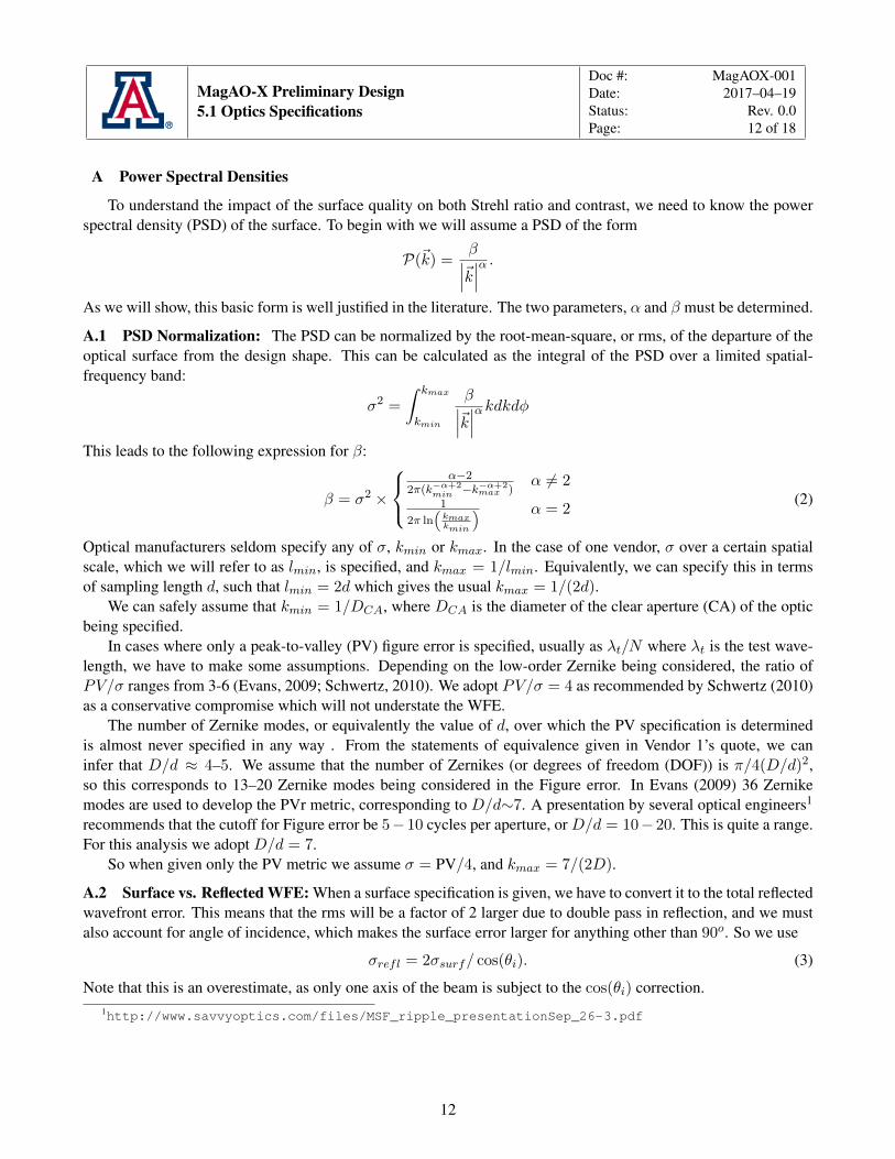
A Power Spectral Densities
To understand the impact of the surface quality on both Strehl ratio and contrast, we need to know the powerspectral density (PSD) of the surface. To begin with we will assume a PSD of the form
P(~k) = β∣∣∣~k∣∣∣α .As we will show, this basic form is well justified in the literature. The two parameters, α and β must be determined.
A.1 PSD Normalization: The PSD can be normalized by the root-mean-square, or rms, of the departure of theoptical surface from the design shape. This can be calculated as the integral of the PSD over a limited spatial-frequency band:
σ2 =
∫ kmax
kmin
β∣∣∣~k∣∣∣αkdkdφThis leads to the following expression for β:
β = σ2 ×
α−2
2π(k−α+2min −k−α+2
max )α 6= 2
1
2π ln(kmaxkmin
) α = 2(2)
Optical manufacturers seldom specify any of σ, kmin or kmax. In the case of one vendor, σ over a certain spatialscale, which we will refer to as lmin, is specified, and kmax = 1/lmin. Equivalently, we can specify this in termsof sampling length d, such that lmin = 2d which gives the usual kmax = 1/(2d).
We can safely assume that kmin = 1/DCA, where DCA is the diameter of the clear aperture (CA) of the opticbeing specified.
In cases where only a peak-to-valley (PV) figure error is specified, usually as λt/N where λt is the test wave-length, we have to make some assumptions. Depending on the low-order Zernike being considered, the ratio ofPV/σ ranges from 3-6 (Evans, 2009; Schwertz, 2010). We adopt PV/σ = 4 as recommended by Schwertz (2010)as a conservative compromise which will not understate the WFE.
The number of Zernike modes, or equivalently the value of d, over which the PV specification is determinedis almost never specified in any way . From the statements of equivalence given in Vendor 1’s quote, we caninfer that D/d ≈ 4–5. We assume that the number of Zernikes (or degrees of freedom (DOF)) is π/4(D/d)2,so this corresponds to 13–20 Zernike modes being considered in the Figure error. In Evans (2009) 36 Zernikemodes are used to develop the PVr metric, corresponding to D/d∼7. A presentation by several optical engineers1
recommends that the cutoff for Figure error be 5− 10 cycles per aperture, or D/d = 10− 20. This is quite a range.For this analysis we adopt D/d = 7.
So when given only the PV metric we assume σ = PV/4, and kmax = 7/(2D).
A.2 Surface vs. Reflected WFE: When a surface specification is given, we have to convert it to the total reflectedwavefront error. This means that the rms will be a factor of 2 larger due to double pass in reflection, and we mustalso account for angle of incidence, which makes the surface error larger for anything other than 90o. So we use
σrefl = 2σsurf/ cos(θi). (3)
Note that this is an overestimate, as only one axis of the beam is subject to the cos(θi) correction.1http://www.savvyoptics.com/files/MSF_ripple_presentationSep_26-3.pdf
12

MagAO-X Preliminary Design5.1 Optics Specifications
Doc #: MagAOX-001Date: 2017–04–19Status: Rev. 0.0Page: 13 of 18
Figure 9: Measured PSDs of Flats. (a) is for 25 mm Al coated BK7 with λ/10 and λ/20 P-V from Alcock et al. (2010). (b)-(d)are from Duparre et al. (2002). (b) is a polished fused-silica flat, (c) is a polished fused-silica flat, and (d) is polished Zerodur665. Based on these results we adopt α = 2.0 for flats.
A.3 PSD Index: The value of α for a selection of flats was determined by “fit-by-eye” to PSDs presented inAlcock et al. (2010) and Duparre et al. (2002). The fits are illustrated in Figure 9. We adopt α = 2 based on theseresults.
PSDs for aspheric optics are difficult to find in the literature. The one example located so far is by Tinker &Xin (2013). Examples for 2 optics are shown in Figure 10. These results imply α ≈ 1.6 for OAPs. In a reportprovided by a vendor for a single optic, they found α = 1.55 by fitting PSD data. We will use 1.55 for all OAPs.
A.4 Surface Roughness: According to ISO-10110-8, the surface roughness is specified over length scales of 85µm to 2.5 µm. Based on the plots from Tinker & Xin (2013) shown in Figure 10 we will assume the PSD is whitein this range. That is
Psr = βsr (4)
with βsr constant. The normalization for the PSD in this range is
βsr =σ2sr
π(k2max − k2min)(5)
13

MagAO-X Preliminary Design5.1 Optics Specifications
Doc #: MagAOX-001Date: 2017–04–19Status: Rev. 0.0Page: 14 of 18
Figure 10: PSDs of manufactured SiC OAPs from Tinker & Xin (2013). (a) and (b) are cuts from the PSD of 58 mm f/1.4 OAP.(c) and (d) are cuts from a 150 mm f/1.7 OAP. The green lines show a rough “fit-by-eye” to the data.
Figure 11
14

MagAO-X Preliminary Design5.1 Optics Specifications
Doc #: MagAOX-001Date: 2017–04–19Status: Rev. 0.0Page: 15 of 18
where σsr is the surface roughness RMS, kmax = 1/2.5 µm, and kmin = 1/85 µm.
A.5 Inner Scale: Note the fall-off in the PSDs at higher spatial frequencies. In Alcock et al. (2010) it is claimedthat these are due to instrument and measurement artifacts. However, the roll-off in the PSD evident in the OAPresults seems to be real. This is confirmed by considering the surface roughness of these optics as we just did,since the simple power-law can not extend extend to infinitely high spatial frequencies and still produce the surfaceroughness. As is evident in Figure 10 there must be a roll-off in order to meet the surface roughness specification.This roll-off evidently has the form of an inner-scale, which can be modeled with a PSD of the form
P(~k) = β∣∣∣~k∣∣∣α e−(kl0)2 (6)
where l0 is the inner scale. This is illustrated in Figure 12. For the OAPs shown in 10 we estimate l0∼0.3. ThePSDs for flats are measured at much higher spatial frequencies and do not show the same behavior, so we do notapply an inner scale to the flats.
A.6 Outer Scale: There is also a flattening at low spatial frequencies in some of the PSDs, pointing to an outerscale effect. We model this in the usual way with parameter L0. L0 = 15 mm gives a reasonable match to typicalOAP PSDs.
A.7 Complete PSD: Taking all of the above into account we have the final complete PSD
P(~k) = β((1/L0)2 +
∣∣∣~k∣∣∣2)α/2 e−(|~k|l0)2 + βsr. (7)
A.8 Projections: The above characteristics apply to the entire CA. In general, the beam will be smaller than this,and be of different size on each optic in the instrument. To compensate, we project each PSD back to the primarymirror. To start with, the variance on the entire optic is
σCA = βCA
∫ kmax
1/DCA
1
kαkdkdφ
and across the beam we have
σbeam = βCA
∫ 1/2d
1/Dbeam
1
kαkdkdφ.
Now we assert thatσpri = σbeam
and thatD
d= n = constant
for both the beam and the primary mirror. We then have
βpri =
(Dpri
Dbeam
)−α+2
βCA (8)
for normalizing the PSD projected onto the primary mirror.Both L0 and l0 scale linearly as Dpri/DCA.
15

MagAO-X Preliminary Design5.1 Optics Specifications
Doc #: MagAOX-001Date: 2017–04–19Status: Rev. 0.0Page: 16 of 18
10−6
10−4
10−2
100
102
104
0.01 0.1 1 10 100
DM
cont
rolb
and
Surf.rough.band
l0=
0.7l0 =
0.3
Surf
ace
spec
.ban
d
PSD
[nm
2m
m2]
k [mm−1]
PrecisionHigh Precision
2.0 nm Surf. Rough.1.0 nm Surf. Rough.
Figure 12: The complete PSD as modeled by Equation 7. Here we show PSDs for an OAP vendor’s specifications, withα = 1.55, L0 = 15 mm, two choices for l0, and 1 nm surface roughness. Various spatial frequency bands of interest are noted.
B Clay M1
Buddy Martin of SOML provided the post-polishing measurements of the surface. The data file was processedusing the C code provided by him. The header of the file contained
! Diffraction International conversion from Durango to Code V! ACQ S/N: 0003-992161670! Part #:! Serial #:! Surface:! Data: 1:1]! Subtractions: PST TLT PWR AST CMA SA3 MOR! ROI is pixels X=11 thru X=243, Y=17 thru Y=249
GRD 233 233 WFR WVL 0.632820 SSZ 65536 NDA 32767
The short data values were scaled by the indicated value to be in nm of surface height in single precision. The
16

MagAO-X Preliminary Design5.1 Optics Specifications
Doc #: MagAOX-001Date: 2017–04–19Status: Rev. 0.0Page: 17 of 18
following plots show the results of a PSD analysis. Figure 1 shows the raw map as extracted from the data file.Figure 13 shows the 2D PSD of the masked surface. An annular Hann window was applied, and the PSD was
renormalized to have total variance corresponding to 12.52 nm rms.
−15
−10
−5
0
5
10
15
−15 −10 −5 0 5 10 15
ky
[m−1]
kx [m−1]
10−3
10−2
10−1
100
101
Pow
erD
ensi
ty[n
m2
m2]
Figure 13: PSD of M1 surface.
Figure 14 shows the PSF of an image formed by using the masked surface as a pupil plane phase aberration inreflection (multiplied by 2) at 656 nm (Hα).
Figure 15 shows the image formed assuming an ideal coronagraph.
References
Alcock, S. G., Ludbrook, G. D., Owen, T., & Dockree, R. 2010, in Proc. SPIE, Vol. 7801, Advances in Metrologyfor X-Ray and EUV Optics III, 780108
Duparre, A., Ferre-Borrull, J., Gliech, S., et al. 2002, Applied Optics, 41, 154
Evans, C. J. 2009, Optical Engineering, 48, 043605
Noll, R. J. 1976, Journal of the Optical Society of America (1917-1983), 66, 207
Schwertz, K. 2010, Master’s thesis, The University of Arizona, Tucson, AZ
Tinker, F., & Xin, K. 2013, in Proc. SPIE, Vol. 8837, Material Technologies and Applications to Optics, Structures,Components, and Sub-Systems, 88370M
17

MagAO-X Preliminary Design5.1 Optics Specifications
Doc #: MagAOX-001Date: 2017–04–19Status: Rev. 0.0Page: 18 of 18
−1
−0.5
0
0.5
1
−1 −0.5 0 0.5 1
y[a
s]
x [as]
10−5
10−4
10−3
10−2
10−1
100
Con
tras
tto
Peak
Figure 14: PSF of M1 at Hα.
−1
−0.5
0
0.5
1
−1 −0.5 0 0.5 1
y[a
s]
x [as]
10−7
10−6
10−5
10−4
10−3
10−2C
ontr
astt
oPe
ak
Figure 15: PSF of M1 at Hα with ideal coronagraph. The 6 spots are due to print-through of the hexagonal honeycombstructure, and are observed in MagAO+VisAO diffraction-limited images.
18