DMRB VOLUME 2 SECTION 4 PART 2 - BD 43/03 -THE ... · PDF filefebruary 2003 design manual for...
38
February 2003 DESIGN MANUAL FOR ROADS AND BRIDGES VOLUME 2 HIGHWAY STRUCTURES: DESIGN (SUBSTRUCTURES AND SPECIAL STRUCTURES) MATERIALS SECTION 4 PAINTS AND OTHER PROTECTIVE COATINGS PART 2 BD 43/03 THE IMPREGNATION OF REINFORCED AND PRESTRESSED CONCRETE HIGHWAY STRUCTURES USING HYDROPHOBIC PORE-LINING IMPREGNANTS SUMMARY This Standard covers the use of pore lining impregnants on new concrete structures and for those in service. INSTRUCTIONS FOR USE This revised Standard is to be incorporated in the Manual. 1. This document supersedes BD 43/90, BA 33/90 and SB 3/92. 2. Replace existing contents pages for Volume 2 and insert new contents page for Volume 2 dated February 2003. 3. Remove BD 43/90, BA 33/90 and SB 3/92 and archive as appropriate. 4. Insert BD 43/03 in Volume 2, Section 4, Part 2. 5. Please archive this sheet as appropriate. Note: A quarterly index with a full set of Volume Contents Pages is available separately from The Stationery Office Ltd.
Transcript of DMRB VOLUME 2 SECTION 4 PART 2 - BD 43/03 -THE ... · PDF filefebruary 2003 design manual for...
February 2003
DESIGN MANUAL FOR ROADS AND BRIDGES
VOLUME 2 HIGHWAY STRUCTURES:DESIGN(SUBSTRUCTURES ANDSPECIAL STRUCTURES)MATERIALS
SECTION 4 PAINTS AND OTHERPROTECTIVE COATINGS
PART 2
BD 43/03
THE IMPREGNATION OF REINFORCEDAND PRESTRESSED CONCRETEHIGHWAY STRUCTURES USINGHYDROPHOBIC PORE-LININGIMPREGNANTS
SUMMARY
This Standard covers the use of pore lining impregnantson new concrete structures and for those in service.
INSTRUCTIONS FOR USE
This revised Standard is to be incorporated in theManual.
1. This document supersedes BD 43/90, BA 33/90and SB 3/92.
2. Replace existing contents pages for Volume 2 andinsert new contents page for Volume 2 datedFebruary 2003.
3. Remove BD 43/90, BA 33/90 and SB 3/92 andarchive as appropriate.
4. Insert BD 43/03 in Volume 2, Section 4, Part 2.
5. Please archive this sheet as appropriate.
Note: A quarterly index with a full set of VolumeContents Pages is available separately from TheStationery Office Ltd.

BD 43/03
The Impregnation of Reinforcedand Prestressed Concrete Highway
Structures Using HydrophobicPore-Lining Impregnants
Summary: This Standard covers the use of pore lining impregnants on new concretestructures and for those in service.
DESIGN MANUAL FOR ROADS AND BRIDGES
THE HIGHWAYS AGENCY
SCOTTISH EXECUTIVE DEVELOPMENT DEPARTMENT
WELSH ASSEMBLY GOVERNMENTLLYWODRAETH CYNULLIAD CYMRU
THE DEPARTMENT FOR REGIONAL DEVELOPMENTNORTHERN IRELAND

Volume 2 Section 4Part 2 BD 43/03
February 2003
REGISTRATION OF AMENDMENTS
Amend Page No Signature & Date of Amend Page No Signature & Date ofNo incorporation of No incorporation of
amendments amendments
Registration of Amendments

Volume 2 Section 4Part 2 BD 43/03
February 2003
REGISTRATION OF AMENDMENTS
Amend Page No Signature & Date of Amend Page No Signature & Date ofNo incorporation of No incorporation of
amendments amendments
Registration of Amendments

VOLUME 2 HIGHWAY STRUCTURES:DESIGN(SUBSTRUCTURES ANDSPECIAL STRUCTURES)MATERIALS
SECTION 4 PAINTS AND OTHERPROTECTIVE COATINGS
PART 2
BD 43/03
THE IMPREGNATION OF REINFORCEDAND PRESTRESSED CONCRETEHIGHWAY STRUCTURES USINGHYDROPHOBIC PORE-LININGIMPREGNANTS
Contents
Chapter
1. Introduction
2. Scope
3. Safety
4. New Construction
5. Structures in Service
6. Structural Elements to be Impregnated
7. Measures to be Taken Before Impregnation ofStructures in Service
8. Surface Impregnation Requirements
9. Re-Application of Impregnants
10. Other Concrete Surface Treatments
11. References
12. Enquiries
Appendix 1 Testing Regimes Used by the HighwaysAgency
Appendix 2 New Test Methods Developed by TRL, tobe Included in European Standards, toDetermine the Performance andAcceptance of Pore Lining Impregnants
DESIGN MANUAL FOR ROADS AND BRIDGES
February 2003
Volume 2 Section 4Part 2 BD 43/03
February 2003 1/1
Chapter 1Introduction
1. INTRODUCTION
1.1 This Standard provides criteria and backgroundinformation for the impregnation of reinforced andprestressed concrete elements of highway structures,using hydrophobic pore-lining impregnants to helpprevent and control chloride induced reinforcementcorrosion from de-icing salts, and in marineenvironments.
1.2 Penetration of concrete by chloride ions is theprimary cause of reinforcement corrosion in concretehighway structures. The most effective resistance topenetration is achieved when concrete itself forms awater-resistant barrier. Impregnation of reinforced andprestressed concrete members immediately afterconstruction will provide additional protection againstchloride attack before they come into service, andimproved durability in service. For structures already inservice, where corrosion is not yet occurring,impregnation of reinforced and prestressed concretemembers will help protect them from further attack.Impregnation using hydrophobic pore-lining materialsinvolves treating the concrete surface to form awater-repellent, but vapour-permeable layer whichhelps protect the concrete from the ingress of water andsalt and provides added protection againstreinforcement corrosion. The near surface zone poresand capillaries in the concrete are internally coated, butthey are not filled. There is no film on the surface of theconcrete and there is little visible change to externalappearance.
1.3 This Standard replaces both Standard BD 43/90and Advice Note BA 33/90, ‘Impregnation of ConcreteHighway Structures’ and also Scottish TechnicalMemorandum SB 3/92, and should be read inconjunction with the Specification for Highway Worksand the Notes for Guidance.
1.4 The opportunity has been taken to bring thepreviously published documents (BD 43/90 andBA 33/90) up to date and to combine them, and to bringthem in line with the revised Specification for HighwayWorks and the Notes for Guidance, dated May 2002.This has been undertaken based on experience andfeedback on the application of the existing documents,research work, and to signal the move towards theadoption of European Standards.
1.5 Mandatory requirements are shown in boxed text,and guidance is in plain text.
Volume 2 Section 4Part 2 BD 43/03
February 2003 2/1
Chapter 2Scope
2. SCOPE
2.1 This Standard shall apply to reinforced andprestressed concrete structural elements in newconstruction, and in-service structures.
2.2 The previously published documents (BD 43/90and BA 33/90) drew a distinction between in-servicestructures less than or greater than 6 years old. This hasnow been dropped, since the previous documents havebeen in place for over 10 years, and the distinction isnow irrelevant. The Standard provides criteria to allowdecisions to be made as to whether impregnation isappropriate for any in-service structure.
Volume 2 Section 4Part 2 BD 43/03
February 2003 3/1
Chapter 3Safety
3. SAFETY
3.1 The legal provisions of the various statutoryrequirements for Health and Safety shall beobserved in planning and execution ofimpregnation operations. The main safety aspectswith regard to work on the OverseeingOrganisation’s properties are access, safety zones,traffic signing, and working near trafficked roads.Rigorous precautions are also required in handlingthe impregnants, and providing adequateprotection to the work area, and for operatives.
3.2 The Maintenance Organisation shall consultthe local Environmental Health Officer, and theHealth and Safety Executive, as soon as the scaleand location of the work is known, so that anyprecautions considered necessary can be includedin advance of the Contract. Reference shall also bemade to the Specification for Highway Works andthe Notes for Guidance. On Contracts whereimpregnation operations are taking place, theContractor must fully comply with all Health andSafety legislation including Control of SubstancesHazardous to Health (COSHH) requirements andwith the directives of the relevant Waste DisposalAuthority.
3.3 Where impregnation operations are takingplace in the vicinity of water or sensitiveenvironments, full consultation shall take placewith the appropriate responsible parties. Similarly,for work on or near railway lines or other transportinfrastructure, the responsible organisations mustbe consulted and their requirements included inContract documents. Particular care will berequired in the vicinity of occupied properties,businesses and in urban situations.
Volume 2 Section 4Part 2 BD 43/03
February 2003
Chapter 4New Construction
4/1
4. NEW CONSTRUCTION
4.1 New structures shall be impregnated beforethey come into service. Where new structures arebuilt on existing trafficked carriageways they shallbe impregnated at the earliest opportunity, afterconcrete construction is completed, and beforebeing subject to de-icing salt spray. Newconstruction in a marine environment shall beimpregnated as soon as possible, after concreteconstruction is completed. New structures do notrequire testing before impregnation. Referenceshall be made to Clause 8.15 for minimum periodsto elapse after concreting and before impregnation.
4.2 It is preferable to apply the impregnant before theconcrete receives its first exposure to de-icing salts,subject to the prior degradation of any curingmembranes, because a substantial amount of chloridecan enter the concrete by capillary absorption duringthis initial exposure period. Early impregnation isparticularly important in a marine environment, wherethere is a natural and continuously aggressiveenvironment.
4.3 The Maintenance Organisation shall decideon the structural elements to be impregnated inaccordance with the guidance in Clause 6 of thisStandard.

Volume 2 Section 4Part 2 BD 43/03
E
Chapter 5Structures in Service
5. STRUCTURES IN SERVIC
5.1 Structures in service, which have not beenimpregnated previously, shall be impregnatedprovided they comply with certain criteria below.
5.2 There are likely to be few structures in serviceless than 10 years old where impregnation has not takenplace. Such structures are relatively new and thechloride ion concentration at the level of thereinforcement is probably low. The condition of theconcrete in these structures is assumed to be good. Sitetesting prior to impregnation is not considered essential,unless there are visual signs to the contrary, ie ruststaining, cracking and concrete spalling. Where silicate-based curing membranes have been used, it is possiblethat degradation of the membrane has not fully occurredand this may cause difficulties during application andreduce the effectiveness of impregnation. If there is anydoubt, it would be prudent to test for the presence ofany curing membrane.
5.3 For structures over 10 years old, and which havenot been previously impregnated, current practices varyon the basis for decisions on whether to undertakeimpregnation. This can be assessed by visualindications alone, and supplemented with ‘fingertip’inspection and ‘hammer tap’ surveys to detectdelamination. The alternative is to undertake moreextensive preliminary testing as part of an ongoingmanagement regime for structures. These testingarrangements are outlined in Appendix 1, and representthe current practice adopted by the Highways Agency inEngland.
5.4 The Overseeing Organisation, inconsultation with the Maintenance Organisation,shall decide on the type and extent of testing to beundertaken to determine whether structures orparticular elements should be impregnated.
5.5 The Maintenance Organisation shall decideon the structural elements to be impregnated, inaccordance with the guidance in Clause 6 of thisStandard.
5.6 Structural elements to be impregnated shallbe free from rust staining, cracking, delaminationand spalling. Where there are defects present, otherrepairs may be necessary before impregnation isundertaken.
February 2003
5.7 Decisions on when to impregnate structures inservice are not dealt with within this Standard. They arematters to be decided in consultation between theMaintenance Organisation and the OverseeingOrganisation. Normal practice would be to undertakeimpregnation work in association with other plannedmaintenance operations, though separate contracts havebeen set up to undertake impregnation on a number ofstructures.
5/1

Volume 2 Section 4Part 2 BD 43/03
TS TO BE IMPREGNATED
Chapter 6Structural Elements to be Impregnated
6. STRUCTURAL ELEMEN
6.1 Within the structural stock there is a wide varietyof structural types and span arrangements etc.Consequently all parts of a structure are not equally atrisk from chloride attack. Unless the structure is in amarine environment, the risk depends upon the degreeof exposure to de-icing salt, which in turn will dependon the geometry, design and location of individualstructural elements. It is highly desirable to treat allexposed reinforced and prestressed concrete surfacessubjected to de-icing salt spray and/or possible leakagefrom deck joints. Where part of a structural element lieswithin the affected zone then all that face of an elementshould be impregnated. The following is intended as aguide:
(a) Piers, columns, crossheads and abutments within8 metres of the edge of the carriageway subjectedto de-icing salt spray.
(b) Piers, columns, crossheads and abutments with adeck joint above, but with no provision forpositive drainage. Where accessible, the tops ofthese members should also be treated.
(c) Bearing shelves, ballast walls and deck ends witha deck joint above, where accessible.
(d) Concrete parapets and parapet plinths (allinclinations), and concrete deck surfaces notprotected with deck waterproofing.
(e) Deck beams and soffits directly over, and within8 metres of the edge of, the carriageway.
(f) Wingwalls with parts within 8 metres of the edgeof carriageway.
(g) Retaining walls within 8 metres of the edge ofthe carriageway.
February 2003
6.2 In marine environments, all exposedstructural concrete elements are potentially at riskof chloride attack and shall be impregnated.Columns and soffits over brackish water shall alsobe impregnated.
6.3 A detailed record shall be made of themembers treated, and recorded on as-builtdrawings, and the materials detailed in theMaintenance Manual for all structures, both fornew and in-service structures. Reference shall bemade to BA62 ‘As built operational andmaintenance records for highway structures’ and toBD63 and BA63 ‘Inspection of highwaystructures’ for requirements.
6/1
Volume 2 Section 4Part 2 BD 43/03
EN BEFORERUCTURES IN SERVICE
d Drip Strips on Bridge Deck Soffits
Chapter 7Measures to be Taken Before Impregnation of Structures in Service
7. MEASURES TO BE TAKIMPREGNATION OF ST
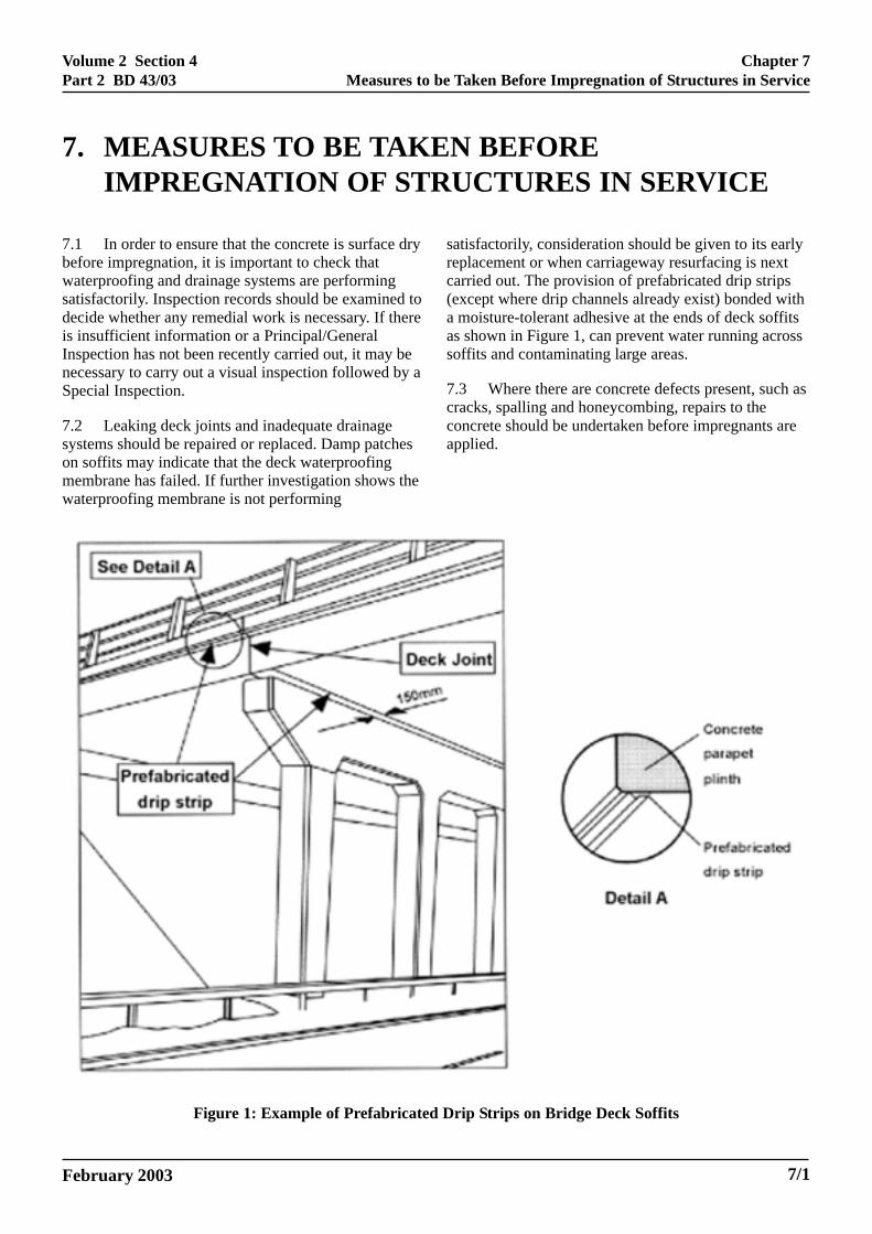
7.1 In order to ensure that the concrete is surface drybefore impregnation, it is important to check thatwaterproofing and drainage systems are performingsatisfactorily. Inspection records should be examined todecide whether any remedial work is necessary. If thereis insufficient information or a Principal/GeneralInspection has not been recently carried out, it may benecessary to carry out a visual inspection followed by aSpecial Inspection.
7.2 Leaking deck joints and inadequate drainagesystems should be repaired or replaced. Damp patcheson soffits may indicate that the deck waterproofingmembrane has failed. If further investigation shows thewaterproofing membrane is not performing
Figure 1: Example of Prefabricate
February 2003
satisfactorily, consideration should be given to its earlyreplacement or when carriageway resurfacing is nextcarried out. The provision of prefabricated drip strips(except where drip channels already exist) bonded witha moisture-tolerant adhesive at the ends of deck soffitsas shown in Figure 1, can prevent water running acrosssoffits and contaminating large areas.
7.3 Where there are concrete defects present, such ascracks, spalling and honeycombing, repairs to theconcrete should be undertaken before impregnants areapplied.
7/1
Volume 2 Section 4Part 2 BD 43/03
N REQUIREMENTS
Chapter 8Surface Impregnation Requirements
8. SURFACE IMPREGNATIO
8.1 Impregnation is carried out by spraying concretesurfaces with a hydrophobic pore-lining material whichreacts with the silicates and moisture present. Thisproduces a water-repellant but vapour-permeable layerthat inhibits the ingress of water and chloride ions.
8.2 Effectiveness of this layer is determined by thequality of the hydrophobisation and the strength andpermanence of the bond between molecules of theimpregnant and the concrete substrate, and is notdirectly dependent on the depth of penetration.Impregnation undertaken in the UK is known to beeffective for at least 15 years, provided it is appliedcorrectly. Longer service life is anticipated. Howeverconcrete surfaces subject to physical abrasion anddegradation mechanisms may be subject to shorterservice lives, through loss of the impregnated surface.
8.3 The application rates given in the Specificationfor Highway Works and the Notes for Guidance areassumed to be appropriate for normal coverage usingapproved equipment, and the specified impregnant(refer to clause 8.4). Alternative materials may beaccepted, but must be applied in accordance withmanufacturers’ requirements and subject to asatisfactory proving trial by the Contractor.
8.4 Generally, in the UK, silane has been used forimpregnation of concrete. Silane is a generic descriptor,and the current Specification for Highway Works andthe Notes for Guidance require the use of monomericalkyl (isobutyl) – trialkoxy silane with a minimumactive content of 92%. There has been opportunity forthe submission of alternative impregnants foracceptance by the Overseeing Organisation, based onproven evidence of their durability and ability toprovide an effective water repellant, butvapour-permeable layer at the concrete surface, for aperiod of not less than 15 years after application.However a new European Standard currently underdevelopment will require compliance with tests for‘pore-lining impregnants’. In particular two testsoriginally developed by TRL have been included, anddetails are provided in Appendix 2 of this Standard. It isanticipated that by compliance with these tests and thequoted acceptance criteria, this will allow other pore-lining impregnants to be used, particularly variantforms of silane and siloxanes.
8fhwnHabmtof
a
b
c
d
e
8amhTc
8ifCrsTm
February 2003
.5 As a result of some past site problems in theraudulent use of adulterated materials, where silaneas been found to be contaminated with paraffin orhite spirit, and without any other visual indications, aew test has been introduced into the Specification forighway Works to allow discrimination of compliant
nd non-compliant transparent materials. The test isased on the determination of the refractive index of theaterial, which shall comply with the value stated in
he manufacturer’s product specification, within a limitf 0.003 units. The refractive index shall be checked asollows:
) Collect samples of the material from a newlyopened container and from the spraying nozzle.
) Measure the refractive index of three samplesfrom both the container and spray nozzle using aportable refractometer.
) Measure the temperature of the samples (portablerefractometers have temperature measuringcapability).
) Correct the refractive index measurements to thetemperature stated in the manufacturer’s productspecification.
) If the temperature corrected measured value ofthe refractive index exceeds the manufacturer’sspecified value by more than 0.003 units then alaboratory check shall be undertaken to confirmcompliance. If the material still does not meetthese requirements, it shall not be used.
.6 Impregnant materials received on site shall beccompanied by a Certificate of Compliance. Noaterial shall be used in the works until the certificate
as been accepted by the Overseeing Organisation.hey shall be delivered to site in sealed airtightontainers
.7 Care should be taken on site to ensure thatmpregnants are stored in a secure facility that has a dryrost-free environment and protected from direct heat.ontainers are to remain sealed until their contents are
equired for use. The contents of any opened containerhall be used within 48 hours or else disposed of safely.his is because the specified silane hydrolises withoisture in the atmosphere.
8/1
Volume 2 Section 4Part 2 BD 43/03
Chapter 8Surface Impregnation Requirements
8.8 To apply the impregnant, spraying equipment isgenerally required, using a power driven, continuouslycirculating, pumped system operating at a low nozzlepressure to avoid atomisation. Care must be taken toprevent water from entering any part of the equipment.Nozzle pressure must be monitored by a pressure gaugeinstalled between the trigger valve and spray lance.Should the pumping system require to be stopped, a‘kill’ switch is to be provided. The type of nozzle usedand spraying distance shall be in accordance with themanufacturer’s instructions.
8.9 Silane is classed as a toxic material and is anirritant to human tissue and so it is essential to adherestrictly to current Health and Safety legislation, andmanufacturers’ recommendations, and employprotective measures when handling and spraying.Similar requirements will apply to other impregnants.Contractors are required to ensure that only fully-trained operatives undertake impregnation operations,and must carry out advance trials to verify procedures.In the case of spillages, the Contactor must immediatelytake action to limit the extent of the spillage and theOverseeing Organisation and the other relevantresponsible authorities must be informed at once (asnoted in Clause 3).
8.10 Measures must be taken to ensure that noimpregnant enters into any drainage system orwatercourse. The Contractor is required to obtain allnecessary written permissions and licences from theappropriate responsible authorities, prior toimpregnation operations above or adjacent to anywatercourse (as noted in Clause 3).
8.11 Measures must also be taken to ensure that noimpregnant comes into contact with any humans,animals, vegetation or vehicular traffic by providingsuitable and adequate protection and trafficmanagement. The Contractor is required to obtainapproval from the Maintenance Organisation and allothers licences, agreements and permissions associatedwith traffic safety, management and protectivemeasures in advance of the commencement ofimpregnation operations (as noted in Clause 3).
8.12 Special precautions must be taken forimpregnation operations over, or adjacent, towatercourses which will require protective sheeting orcomplete encapsulation beneath the structure.Impregnation on structures over, or adjacent to roadswill require protective sheeting or complete,encapsulation. Consideration should also be given tothe introduction of appropriate traffic management andsafety measures. Vegetation that could be subject to
8/2
spray, needs to be covered or otherwise protected, andthe protective covering must be maintained in positionand in good condition.
8.13 Impregnants may damage elastomeric bearings,painted steel surfaces, exposed bituminous materials,and joint sealants adjacent to structural elements andthe Specification for Highway Works and the Notes forGuidance include requirements to mask off, or cover,these components and materials before and duringimpregnation operations. After completion ofimpregnation operations, all contaminated protectivesheeting and materials used for masking or coveringmust be safely disposed of to licensed waste disposalfacilities.
8.14 Critical to the success of the impregnationoperation is the surface condition of the concrete. To beeffective, the areas to be treated must be protected fromadverse effects of the weather and be surface dry for aminimum of 24 hours before application commences.Artificial drying of surfaces is not acceptable as it has atendency to continue to draw moisture to the surface ofthe concrete by capillary action from within theconcrete, when the drying equipment is removed.Depending on climatic conditions, it may be necessaryto protect surfaces to be treated to ensure that they aresurface dry before impregnation. In a marineenvironment, impregnation should be carried out at theearliest opportunity after it has been demonstrated thatthere are no deposits of the curing membraneremaining. Surfaces must also be free from loose ordeleterious matter and residues of curing membranes,release and graffiti removal agents. The presence of acuring membrane or its residual effects may renderimpregnation ineffective. This is particularly importantto check when silane is to be applied less than a monthafter the concrete was placed. In service structures mustbe cleaned with a stiff bristle handbrush to removesurface deposits, wirebrushing or by light grit blasting.High pressure grit blasting is not acceptable as itdamages the surface of the concrete, nor is water jettingor steam cleaning as a means of surface preparation, asthey wet the concrete substrate. In exceptionalcircumstances, where there is substantialcontamination, water jetting or steam cleaning may beused with care, subject to a satisfactory trial beingundertaken. However, where this has been allowed,impregnation should not commence for a minimum of48 hours from completion of the cleaning works, andremains subject to the other application and surfacecondition requirements, particularly the need for aperiod of surface dryness of the concrete substrate for aperiod of 24 hours in advance of the impregnationoperation.
February 2003
Volume 2 Section 4Part 2 BD 43/03
Chapter 8Surface Impregnation Requirements
8.15 As a result of research work carried out at TRL,some of the previous requirements for application ofimpregnants have been relaxed. In particular theimpregnation operations may be undertaken for newconstruction (both insitu and precast concrete) not lessthan 7 days after the concrete has been placed for newconstruction, or 3 days where concrete repairs havebeen completed on a structural element. However,attention is particularly drawn to the need to complywith the surface condition requirements at 8.14.Impregnation operations using the specified silaneshould be carried out in a single continuous operationfor each application, and applied by continuous spraytechnique giving saturation flooding, working from thelowest level upwards. Two applications are required ata coverage of 300 ml/m² with an interval between eachof at least six hours. This coverage rate must beregularly monitored by determining the quantities ofsilane material used on particular areas of eachstructure. Achieving the required rate may result insome loss of material, by run down and evaporation.Application of silane can be judged by a characteristic‘wet look’ to the concrete surface.
8.16 Environmental conditions for impregnationoperations shall be imposed. The work should not beundertaken when the shade air temperature is below5°C, or when the temperature of the concrete surface isgreater than 25°C, or when the wind speed is in excessof 8 km/hr (unless the working area is fullyencapsulated by appropriate protective measures).Impregnated concrete surfaces must be protected fromrain and spray during application and for at least 6hours after completion.
8.17 The Specification for Highway Works and theNotes for Guidance make provision for the Contractorto carry out impregnation trials where required in theContract. The Contractor is required to demonstrate thatthe proposed method of working will meet the Contractrequirements, on both horizontal and vertical trialpanels.
February 2003 8/3

Volume 2 Section 4Part 2 BD 43/03
February 2003
9. RE-APPLICATION OF IMPREGNANTS
9.1 Impregnation using monomeric alkyl (isobutyl)-trialkoxy silane is known from research evidence to behighly effective for at least 15 years provided it isapplied correctly. Longer service lives are anticipated.However it is considered advisable, until furtherexperience is gained, to assume that re-application willbe necessary after about 20 years.
9.2 Determination of the need for re-application ofan impregnant will be subject to the assessment oftesting carried out as part of the periodic managementand inspection of structures in service. When significantchanges in half-cell potentials are observed, and criticallevels are approached over significant areas of theconcrete element, then consideration may be given tore-application of an impregnant. Care must be taken toensure compatibility with the initially appliedtreatment. Reference should be made to Clause 5.3, andthe testing procedures adopted by the OverseeingOrganisation.
Chapter 9Re-Application of Impregnants
9/1
Volume 2 Section 4Part 2 BD 43/03
February 2003
10. OTHER CONCRETE SURFACE TREATMENTS
10.1 The policy on concrete surface coatings is thatthey are not to be applied, unless there is an overridingengineering justification to do so. Where coatings areproposed, and impregnants are also to be used (byvirtue of this Standard), then the MaintenanceOrganisation should ensure that there is compatibilitybetween the materials. It is essential to ensure that thevapour transmissibility and hydrophobic properties ofthe impregnant are not adversely affected, and that theperformance of the coating, particularly long-termadhesion, is effective.
10.2 BA57 refers to other materials and methodswhere research has provided evidence of enhanceddurability against chloride induced corrosion.Where these materials and methods have beenused, pore lining impregnants shall be used inaccordance with this Standard.
Chapter 10Other Concrete Surface Treatments
10/1

Volume 2 Section 4Part 2 BD 43/03
February 2003
Chapter 11References
11/1
11. REFERENCES
1. Health and Safety at Work etc Act 1974.Factories Act 1961.Health and Safety legislation relevant toOverseeing Organisation.Section 4 Approved Code of Practice(ACOP): Management of Health and Safety atWork.
Northern Ireland
Workplace (Health, Safety and Welfare)Regulations (NI) 1993Confined Spaces Regulations (NI) 1999
2. Methods to determine chloride concentrations inin-situ concrete, Transport Road ResearchLaboratory, Contractor Report 32.
3. BRE Information Paper IP 21/86, Determinationof chloride and cement of hardened concrete.

Volume 2 Section 4Part 2 BD 43/03
February 2003 12/1
12. ENQUIRIES
All technical enquiries or comments on this Standard should be sent in writing as appropriate to:
Chief Highway EngineerThe Highways AgencyRoom B153ARomney House43 Marsham Street G CLARKELondon SW1P 3HW Chief Highway Engineer
Chief Road EngineerScottish Executive Development DepartmentVictoria QuayEdinburgh J HOWISONEH6 6QQ Chief Road Engineer
Chief Highway EngineerTransport DirectorateWelsh Assembly GovernmentLlywodraeth Cynulliad CymruCrown Buildings J R REESCardiff Chief Highway EngineerCF10 3NQ Transport Directorate
Director of EngineeringDepartment for Regional DevelopmentRoads ServiceClarence Court10-18 Adelaide Street G W ALLISTERBelfast BT2 8GB Director of Engineering
Chapter 12Enquiries
Volume 2 Section 4Part 2 BD 43/03
February 2003
APPENDIX 1 - TESTING REGIMES USED BY THEHIGHWAYS AGENCY
A1.1 This Appendix contains information about the testing regimes applicable to structures owned by theHighways Agency, as a basis for decision making about impregnation of structures in service over 10 years old, andforms part of an ongoing management process for such structures.
A1.2 Certain reinforced concrete elements require site testing for half-cell potentials to check whether they satisfythe criteria for impregnation, and for chloride contents to establish which members need monitoring afterimpregnation. Prestressed or precast concrete members do not require testing before impregnation. For marinestructures, all exposed concrete elements require assessment.
A1.3 Site testing for half-cell potentials and chloride contents should be confined to concrete elements listed inA1.7(a). These members are subjected to salt traffic spray and/or possible leakage from deck joints. To ensure thatimpregnation is only carried out on members where reinforcement corrosion is not yet occurring, the test criteria inA1.7(c) should be satisfied.
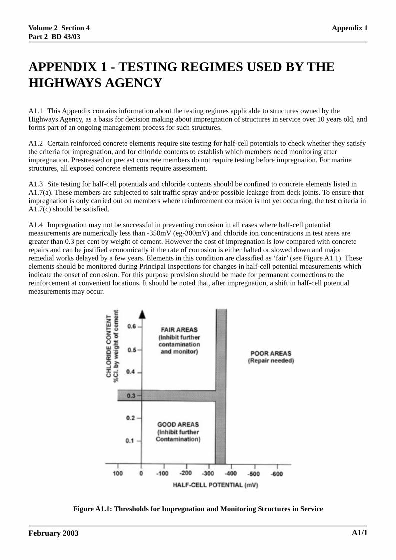
A1.4 Impregnation may not be successful in preventing corrosion in all cases where half-cell potentialmeasurements are numerically less than -350mV (eg-300mV) and chloride ion concentrations in test areas aregreater than 0.3 per cent by weight of cement. However the cost of impregnation is low compared with concreterepairs and can be justified economically if the rate of corrosion is either halted or slowed down and majorremedial works delayed by a few years. Elements in this condition are classified as ‘fair’ (see Figure A1.1). Theseelements should be monitored during Principal Inspections for changes in half-cell potential measurements whichindicate the onset of corrosion. For this purpose provision should be made for permanent connections to thereinforcement at convenient locations. It should be noted that, after impregnation, a shift in half-cell potentialmeasurements may occur.
Figure A1.1: Thresholds for Impregnation and Monitoring Structures in Service
Appendix 1
A1/1
Volume 2 Section 4Part 2 BD 43/03
February 2003
A1.5 If tested members do not satisfy the criteria for impregnation, then the Maintenance Organisation shoulddecide if non-tested areas selected for impregnation should alone be treated.
A1.6 Site testing of structures in service should be carried out during Principal Inspections where possible.
A1.7 Site Test Criteria
(a) The following concrete elements shall satisfy the criteria for half-cell potential in A1.7(c) before beingconsidered for impregnation:
(i) Piers
(ii) Columns
(iii) Crossheads
(iv) Abutments
(v) Wingwalls and retaining walls
(vi) Parapets
(vii) Parapet plinths
For marine structures all exposed concrete elements require assessment.
(b) Site sampling shall only be carried out by specialist testing firms, and laboratory testing by laboratorieswhich have been approved by the United Kingdom Accreditation Service (UKAS), or by equivalentaccreditation bodies, for the required laboratory tests.
(c) Impregnation of reinforced concrete piers, columns, crossheads, abutments, wingwalls, retaining walls,concrete parapets and parapet plinths shall be carried out if, for each element, 95% of half-cell potentialmeasurements are numerically less than -350mV relative to a copper/copper sulfate reference electrode. Thefigure of -350mV represents the critical numerical value above which there is a high risk of corrosionoccurring.
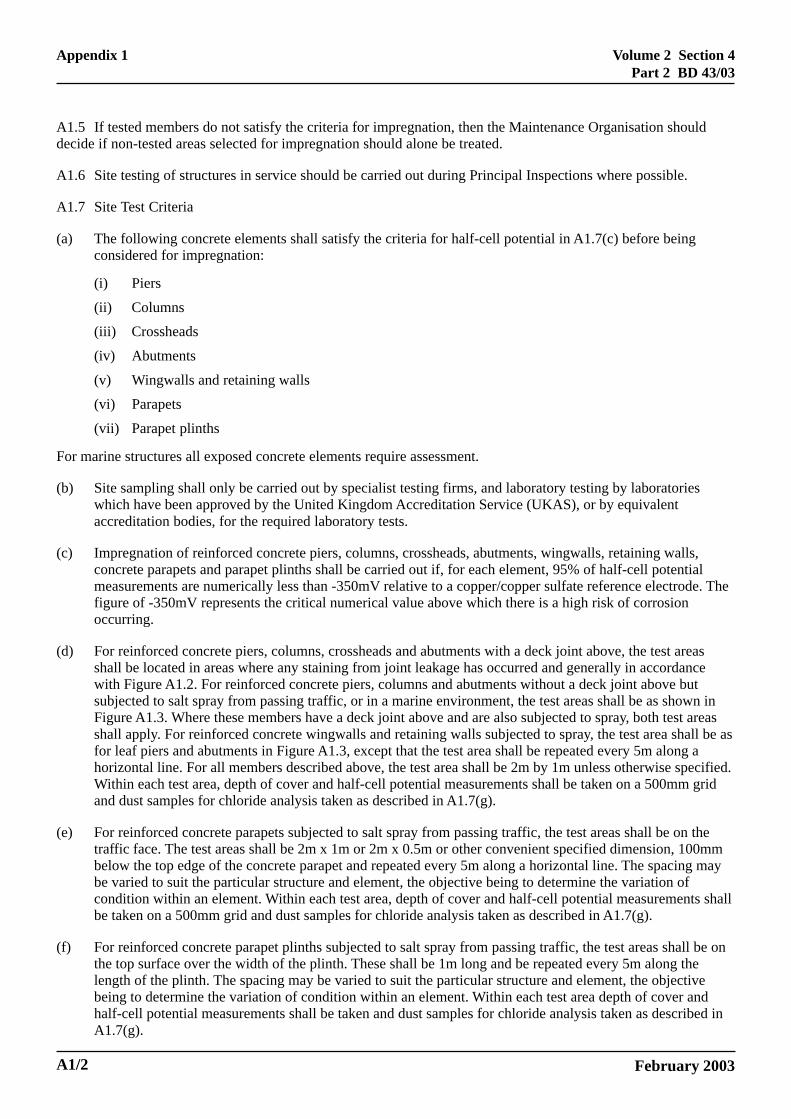
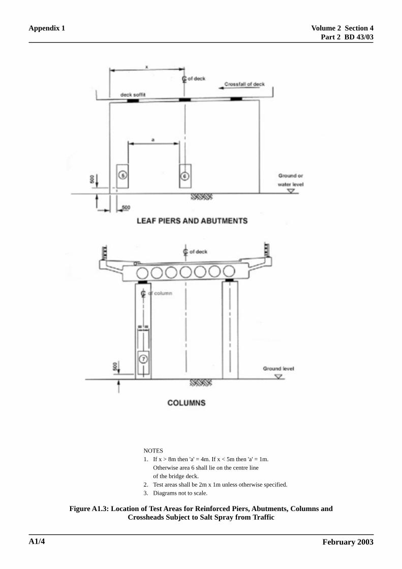
(d) For reinforced concrete piers, columns, crossheads and abutments with a deck joint above, the test areasshall be located in areas where any staining from joint leakage has occurred and generally in accordancewith Figure A1.2. For reinforced concrete piers, columns and abutments without a deck joint above butsubjected to salt spray from passing traffic, or in a marine environment, the test areas shall be as shown inFigure A1.3. Where these members have a deck joint above and are also subjected to spray, both test areasshall apply. For reinforced concrete wingwalls and retaining walls subjected to spray, the test area shall be asfor leaf piers and abutments in Figure A1.3, except that the test area shall be repeated every 5m along ahorizontal line. For all members described above, the test area shall be 2m by 1m unless otherwise specified.Within each test area, depth of cover and half-cell potential measurements shall be taken on a 500mm gridand dust samples for chloride analysis taken as described in A1.7(g).
(e) For reinforced concrete parapets subjected to salt spray from passing traffic, the test areas shall be on thetraffic face. The test areas shall be 2m x 1m or 2m x 0.5m or other convenient specified dimension, 100mmbelow the top edge of the concrete parapet and repeated every 5m along a horizontal line. The spacing maybe varied to suit the particular structure and element, the objective being to determine the variation ofcondition within an element. Within each test area, depth of cover and half-cell potential measurements shallbe taken on a 500mm grid and dust samples for chloride analysis taken as described in A1.7(g).
(f) For reinforced concrete parapet plinths subjected to salt spray from passing traffic, the test areas shall be onthe top surface over the width of the plinth. These shall be 1m long and be repeated every 5m along thelength of the plinth. The spacing may be varied to suit the particular structure and element, the objectivebeing to determine the variation of condition within an element. Within each test area depth of cover andhalf-cell potential measurements shall be taken and dust samples for chloride analysis taken as described inA1.7(g).
A1/2
Appendix 1

Volume 2 Section 4Part 2 BD 43/03
February 2003
NOTES1. If x > 8m then 'a' = 4m. If x < 5m then 'a' = 1m.
Otherwise area 2 shall lie on the centre lineof the bridge deck.
2. Test areas shall be 2m x 1m unless otherwise specified.3. Diagrams not to scale.
Figure A1.2: Location of Test Areas for Reinforced Piers, Abutments, Columns andCrossheads With a Deck Joint Above
Appendix 1
A1/3
Volume 2 Section 4Part 2 BD 43/03
February 2003
NOTES1. If x > 8m then 'a' = 4m. If x < 5m then 'a' = 1m.
Otherwise area 6 shall lie on the centre lineof the bridge deck.
2. Test areas shall be 2m x 1m unless otherwise specified.3. Diagrams not to scale.
Figure A1.3: Location of Test Areas for Reinforced Piers, Abutments, Columns andCrossheads Subject to Salt Spray from Traffic
A1/4
Appendix 1

Volume 2 Section 4Part 2 BD 43/03
February 2003
(g) Within each test area two dust samples for chloride analysis shall be taken from positions of numericallyhigh half-cell potentials. Dust samples shall be removed from reinforced concrete members using a 20 to25mm diameter drill bit and the dust collected by a method described in Reference 3 or other suitablemethod. Samples shall be collected from drillings over a depth of 20mm at the level of the reinforcement.Samples shall be sealed in plastic bags labelled with the location, depth and name of operator. All holesdrilled shall be made good to the satisfaction of the Maintenance Organisation.
(h) Analysis of chloride content in reinforced concrete members shall be done on site by the “Quantab” methodas described in BRE Information Paper IP 21/86 [Reference 3], except that: calcium carbonate shall be usedto neutralise the solution [Reference 2]. Where many analyses are to be undertaken it will be quicker andmay be more economical to use a battery-operated pH meter with a chloride ion selective electrode to readchloride concentrations directly [Reference 2]. Other site testing methods approved by the appropriateregulatory bodies in other member states are also acceptable. The average of the chloride ion analysis resultsfor the two dust samples shall be taken as representative of the chloride ion concentration for the test area atthe level of the reinforcement.
(i) Cement content shall be assumed to be 315 kg/m3 unless positive evidence of a different cement content isavailable.
(j) Where members have been tested and impregnated under A1.7(c), and chloride ion concentrations aregreater than 0.3 per cent by weight of cement in any of the test areas, these members shall be monitored forhalf-cell potentials during future Principal Inspections. Other ongoing management strategies shall also beconsidered.
Appendix 1
A1/5
Volume 2 Section 4Part 2 BD 43/03
February 2003
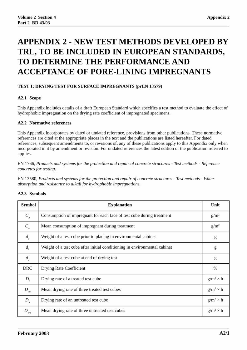
TEST 1: DRYING TEST FOR SURFACE IMPREGNANTS (prEN 13579)
A2.1 Scope
This Appendix includes details of a draft European Standard which specifies a test method to evaluate the effect ofhydrophobic impregnation on the drying rate coefficient of impregnated specimens.
A2.2 Normative references
This Appendix incorporates by dated or undated reference, provisions from other publications. These normativereferences are cited at the appropriate places in the text and the publications are listed hereafter. For datedreferences, subsequent amendments to, or revisions of, any of these publications apply to this Appendix only whenincorporated in it by amendment or revision. For undated references the latest edition of the publication referred toapplies.
EN 1766, Products and systems for the protection and repair of concrete structures - Test methods - Referenceconcretes for testing.
EN 13580, Products and systems for the protection and repair of concrete structures - Test methods - Waterabsorption and resistance to alkali for hydrophobic impregnations.
A2.3 Symbols
Symbol Explanation Unit
Cn Consumption of impregnant for each face of test cube during treatment g/m2
Cm Mean consumption of impregnant during treatment g/m2
d0 Weight of a test cube prior to placing in environmental cabinet g
d1 Weight of a test cube after initial conditioning in environmental cabinet g
d2 Weight of a test cube at end of drying test g
DRC Drying Rate Coefficient %
Dt Drying rate of a treated test cube g/m2 × h
Dtm Mean drying rate of three treated test cubes g/m2 × h
Du Drying rate of an untreated test cube g/m2 × h
Dum Mean drying rate of three untreated test cubes g/m2 × h
APPENDIX 2 - NEW TEST METHODS DEVELOPED BYTRL, TO BE INCLUDED IN EUROPEAN STANDARDS,TO DETERMINE THE PERFORMANCE ANDACCEPTANCE OF PORE-LINING IMPREGNANTS
Appendix 2
A2/1
Volume 2 Section 4Part 2 BD 43/03
February 2003
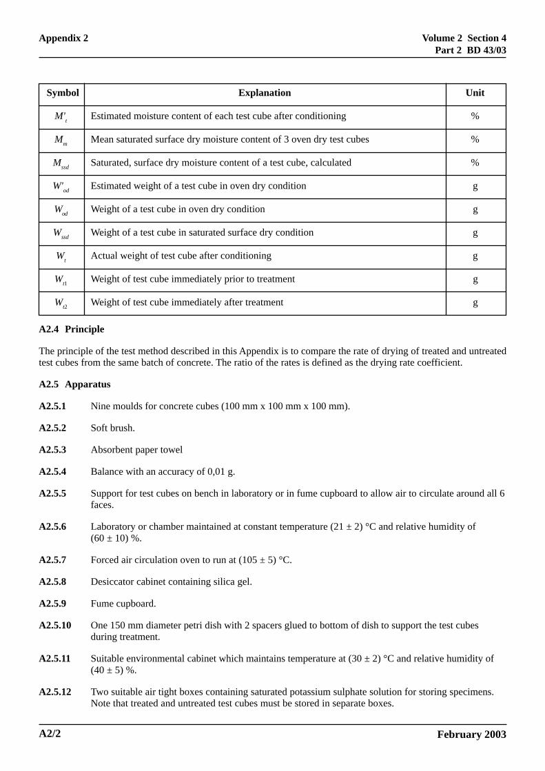
Symbol Explanation Unit
M't Estimated moisture content of each test cube after conditioning %
Mm Mean saturated surface dry moisture content of 3 oven dry test cubes %
Mssd Saturated, surface dry moisture content of a test cube, calculated %
W'od Estimated weight of a test cube in oven dry condition g
Wod Weight of a test cube in oven dry condition g
Wssd Weight of a test cube in saturated surface dry condition g
Wt Actual weight of test cube after conditioning g
Wt1 Weight of test cube immediately prior to treatment g
Wt2 Weight of test cube immediately after treatment g
A2.4 Principle
The principle of the test method described in this Appendix is to compare the rate of drying of treated and untreatedtest cubes from the same batch of concrete. The ratio of the rates is defined as the drying rate coefficient.
A2.5 Apparatus
A2.5.1 Nine moulds for concrete cubes (100 mm x 100 mm x 100 mm).
A2.5.2 Soft brush.
A2.5.3 Absorbent paper towel
A2.5.4 Balance with an accuracy of 0,01 g.
A2.5.5 Support for test cubes on bench in laboratory or in fume cupboard to allow air to circulate around all 6faces.
A2.5.6 Laboratory or chamber maintained at constant temperature (21 ± 2) °C and relative humidity of(60 ± 10) %.
A2.5.7 Forced air circulation oven to run at (105 ± 5) °C.
A2.5.8 Desiccator cabinet containing silica gel.
A2.5.9 Fume cupboard.
A2.5.10 One 150 mm diameter petri dish with 2 spacers glued to bottom of dish to support the test cubesduring treatment.
A2.5.11 Suitable environmental cabinet which maintains temperature at (30 ± 2) °C and relative humidity of(40 ± 5) %.
A2.5.12 Two suitable air tight boxes containing saturated potassium sulphate solution for storing specimens.Note that treated and untreated test cubes must be stored in separate boxes.
A2/2
Appendix 2
Volume 2 Section 4Part 2 BD 43/03
February 2003
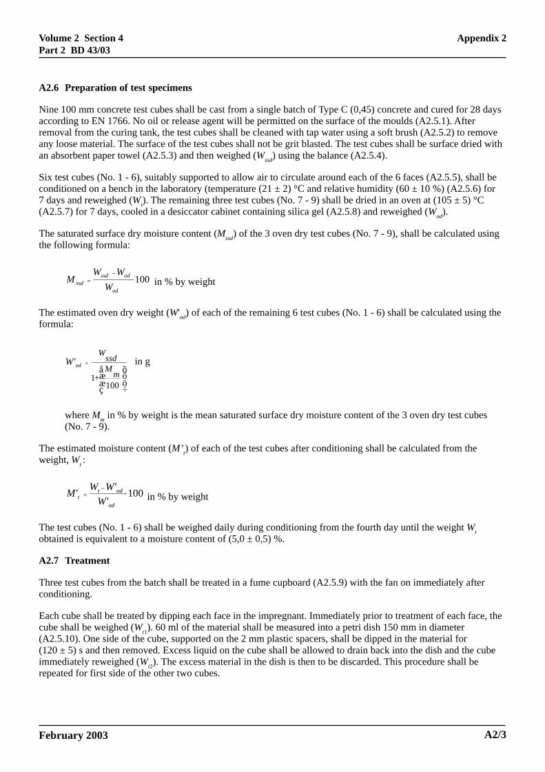
A2.6 Preparation of test specimens
Nine 100 mm concrete test cubes shall be cast from a single batch of Type C (0,45) concrete and cured for 28 daysaccording to EN 1766. No oil or release agent will be permitted on the surface of the moulds (A2.5.1). Afterremoval from the curing tank, the test cubes shall be cleaned with tap water using a soft brush (A2.5.2) to removeany loose material. The surface of the test cubes shall not be grit blasted. The test cubes shall be surface dried withan absorbent paper towel (A2.5.3) and then weighed (Wssd) using the balance (A2.5.4).
Six test cubes (No. 1 - 6), suitably supported to allow air to circulate around each of the 6 faces (A2.5.5), shall beconditioned on a bench in the laboratory (temperature (21 ± 2) °C and relative humidity (60 ± 10 %) (A2.5.6) for7 days and reweighed (Wt). The remaining three test cubes (No. 7 - 9) shall be dried in an oven at (105 ± 5) °C(A2.5.7) for 7 days, cooled in a desiccator cabinet containing silica gel (A2.5.8) and reweighed (Wod).
The saturated surface dry moisture content (Mssd) of the 3 oven dry test cubes (No. 7 - 9), shall be calculated usingthe following formula:
100⋅−
=
od
odssdssd W
WWM in % by weight
The estimated oven dry weight (W'od) of each of the remaining 6 test cubes (No. 1 - 6) shall be calculated using theformula:
öö÷
õææç
å=
1001 mM+
ssdWodW'
where Mm in % by weight is the mean saturated surface dry moisture content of the 3 oven dry test cubes(No. 7 - 9).
The estimated moisture content (M’t) of each of the test cubes after conditioning shall be calculated from theweight, Wt :
001⋅−=
od
odtt W'
W'WM' in % by weight
The test cubes (No. 1 - 6) shall be weighed daily during conditioning from the fourth day until the weight Wtobtained is equivalent to a moisture content of (5,0 ± 0,5) %.
A2.7 Treatment
Three test cubes from the batch shall be treated in a fume cupboard (A2.5.9) with the fan on immediately afterconditioning.
Each cube shall be treated by dipping each face in the impregnant. Immediately prior to treatment of each face, thecube shall be weighed (Wt1). 60 ml of the material shall be measured into a petri dish 150 mm in diameter(A2.5.10). One side of the cube, supported on the 2 mm plastic spacers, shall be dipped in the material for(120 ± 5) s and then removed. Excess liquid on the cube shall be allowed to drain back into the dish and the cubeimmediately reweighed (Wt2). The excess material in the dish is then to be discarded. This procedure shall berepeated for first side of the other two cubes.
in g
Appendix 2
A2/3

Volume 2 Section 4Part 2 BD 43/03
February 2003
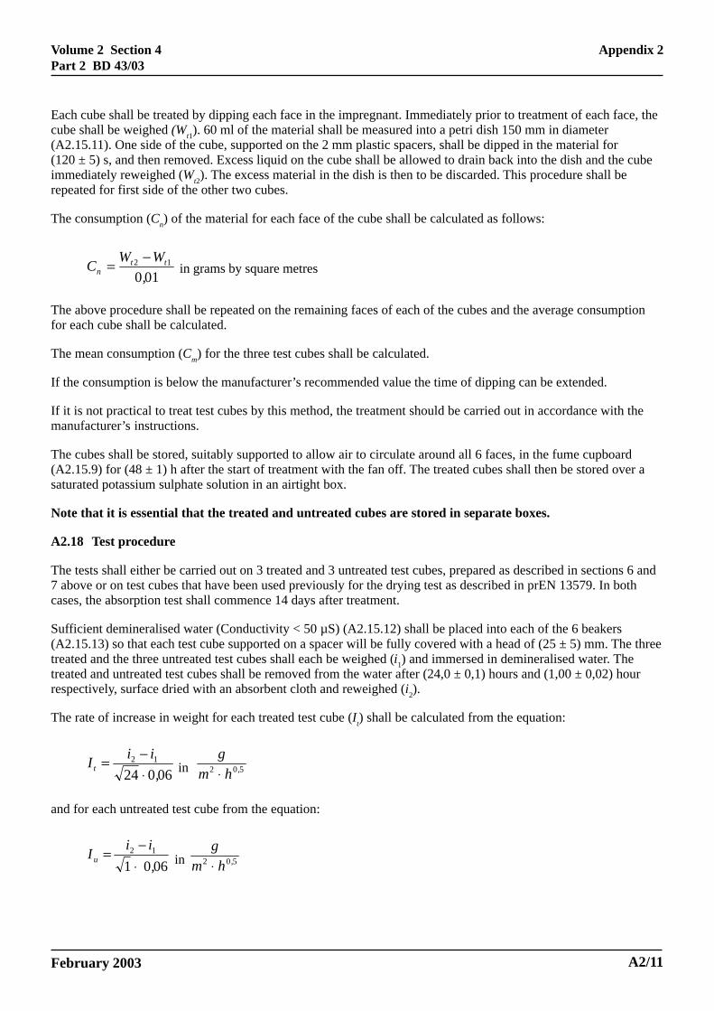
The consumption (Cn) of the material for each face of the cube shall be calculated as follows:
01,012 tt
nWWC −= in grams by square meters
The above procedure shall be repeated on the remaining six faces of each of the cubes and the averageconsumption for each cube shall be calculated.
The mean consumption (Cm) for the three test cubes shall be calculated.
If the consumption is below the manufacturer’s recommended value the time of dipping can be extended.
If it is not practical to treat test cubes by this method, the treatment should be carried out in accordance with themanufacturer’s instructions.
The cubes shall be stored, suitably supported to allow air to circulate around all 6 faces, in the fume cupboard for(48 ± 1) h after the start of treatment with the fan off.
A2.8 Test procedure
General
The drying test shall be carried out on 3 treated and 3 untreated test cubes prepared as in sections A1.6 and A1.7above.
The rate of drying of three treated and three untreated test cubes shall be determined by measuring their weight lossin an environmental cabinet. The treated and untreated test cubes must be tested at different times to avoid crosscontamination.
The drying tests on the untreated test cubes shall be started immediately after the conditioning. The drying test onthe treated test cubes shall be started 48 h after treatment.
Untreated test cubes
The 3 untreated test cubes shall be weighed (d0) and placed in a cabinet with a controlled environment of(30 ± 2) °C and (40 ± 5) % R. H. (A2.5.11) immediately after conditioning and reweighed (d1) after (6,0 ± 0,1) h.The drying test shall be continued for further (18,0 ± 0,1) h. The test cubes shall again be weighed (d2) and thedrying rate (Du) of each test cube shall be calculated as:
0601821
,ddDu ⋅
−= in hm²
g⋅
NOTE In practice, d0 = Wt.
A2/4
Appendix 2
Volume 2 Section 4Part 2 BD 43/03
February 2003
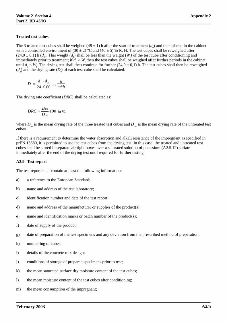
Treated test cubes
The 3 treated test cubes shall be weighed (48 ± 1) h after the start of treatment (d0) and then placed in the cabinetwith a controlled environment of (30 ± 2) °C and (40 ± 5) % R. H. The test cubes shall be reweighed after(24,0 ± 0,1) h (d1). This weight (d1) shall be less than the weight (Wt) of the test cube after conditioning andimmediately prior to treatment; if d1 > Wt then the test cubes shall be weighed after further periods in the cabinetuntil d1 < Wt. The drying test shall then continue for further (24,0 ± 0,1) h. The test cubes shall then be reweighed(d2) and the drying rate (Dt) of each test cube shall be calculated:
0602421
,ddDt ⋅
= − in hm²
g⋅
The drying rate coefficient (DRC) shall be calculated as:
100⋅=um
tm
DDDRC in %
where Dtm is the mean drying rate of the three treated test cubes and Dum is the mean drying rate of the untreated testcubes.
If there is a requirement to determine the water absorption and alkali resistance of the impregnant as specified inprEN 13580, it is permitted to use the test cubes from the drying test. In this case, the treated and untreated testcubes shall be stored in separate air tight boxes over a saturated solution of potassium (A2.5.12) sulfateimmediately after the end of the drying test until required for further testing.
A2.9 Test report
The test report shall contain at least the following information:
a) a reference to the European Standard;
b) name and address of the test laboratory;
c) identification number and date of the test report;
d) name and address of the manufacturer or supplier of the product(s);
e) name and identification marks or batch number of the product(s);
f) date of supply of the product;
g) date of preparation of the test specimens and any deviation from the prescribed method of preparation;
h) numbering of cubes;
i) details of the concrete mix design;
j) conditions of storage of prepared specimens prior to test;
k) the mean saturated surface dry moisture content of the test cubes;
l) the mean moisture content of the test cubes after conditioning;
m) the mean consumption of the impregnant;
Appendix 2
A2/5
Volume 2 Section 4Part 2 BD 43/03
February 2003
n) the drying rate coefficient;
o) date of test and details of the test equipment used;
p) any deviation from the test method specified;
q) date of the report and signature;
r) any other observations.
A2.10 Requirements
In order for an impregnant to be acceptable for use on Highways Agency structures it must be tested on cubes fromtwo separate batches of concrete cast at different times and the mean result from the two batches must satisfy thecriteria given below:
Drying Rate Transmission Coefficient DRC >30%
A2/6
Appendix 2
Volume 2 Section 4Part 2 BD 43/03
February 2003
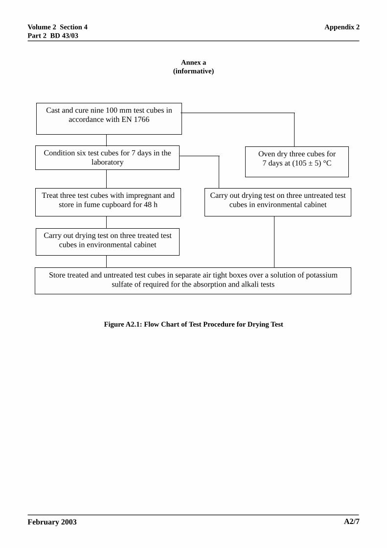
Annex a(informative)
Cast and cure nine 100 mm test cubes in accordance with EN 1766
Condition six test cubes for 7 days in the laboratory
Treat three test cubes with impregnant and store in fume cupboard for 48 h
Oven dry three cubes for 7 days at (105 ± 5) °C
Carry out drying test on three untreated test cubes in environmental cabinet
Carry out drying test on three treated test cubes in environmental cabinet
Store treated and untreated test cubes in separate air tight boxes over a solution of potassium sulfate of required for the absorption and alkali tests
Figure A2.1: Flow Chart of Test Procedure for Drying Test
Appendix 2
A2/7

Volume 2 Section 4Part 2 BD 43/03
February 2003
TEST 2: WATER ABSORPTION AND RESISTANCE TO ALKALI TESTS FOR SURFACEIMPREGNANTS (prEN13580)
A2.11 Scope
This Appendix includes details of a draft European Standard which specifies a test method to evaluate the effect ofa hydrophobic impregnation. It deals with the rate at which treated concrete absorbs water and the alkali resistanceof that surface treatment. The method primarily relates to the protection of concrete structures.
A2.12 Normative references
This Appendix incorporates by dated or undated reference, provisions from other publications. These normativereferences are cited at the appropriate places in the text and the publications are listed hereafter. For datedreferences, subsequent amendments to, or revisions of, any of these publications apply to this Appendix only whenincorporated in it by amendment or revision. For undated references, the latest edition of the publication referred toapplies.
EN 1766, Products and systems for the protection and repair of concrete structures – Test methods – Referenceconcretes for testing.
prEN 13579, Products and systems for the protection and repair of concrete structures – Test methods – Drying testfor hydrophobic impregnation.
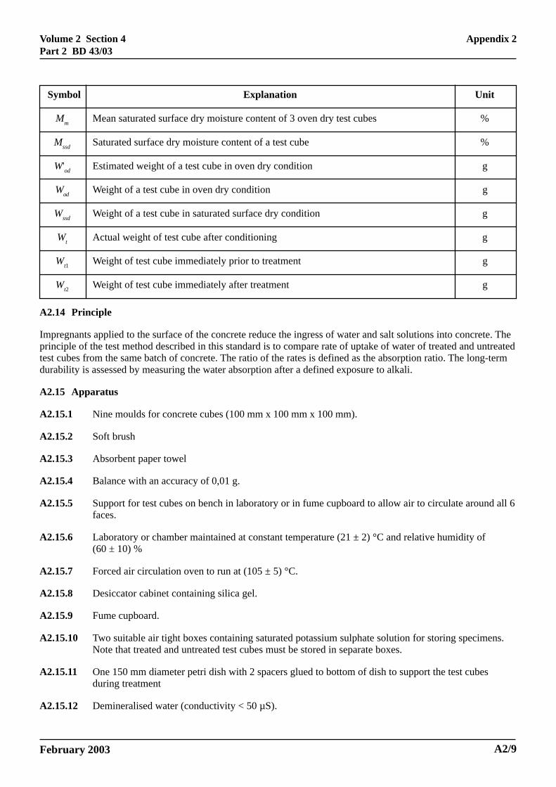
A2.13 Symbols
Symbol Explanation Unit
AR Absorption ratio %
AR(alk) Absorption ratio after exposure to alkali %
Cm Mean consumption of impregnant during treatment g/m2
Cn Consumption of impregnant for each face of test cube during treatment g/m2
i1 Weight of a test cube at start of immersion test g
i2 Weight of a test cube at end of immersion test g
It Rate of increase in weight of a treated test cube g/(m2 × h0,5)
It(alk) Rate of increase in weight of a treated test cube after exposure to alkali g/(m2 × h0,5)
Itm Mean rate of increase in weight of three treated test cubes g/(m2 × h0,5)
Itm(alk) Mean rate of increase in weight of three treated test cubes after exposure to alkali g/(m2 × h0,5)
Iu Rate of increase in weight of an untreated test cube g/(m2 × h0,5)
Ium Mean rate of increase in weight of three untreated test cubes g/(m2 × h0,5)
M't Estimated moisture content of each test cube after conditioning %
A2/8
Appendix 2
Volume 2 Section 4Part 2 BD 43/03
February 2003
Symbol Explanation Unit
Mm Mean saturated surface dry moisture content of 3 oven dry test cubes %
Mssd Saturated surface dry moisture content of a test cube %
W'od Estimated weight of a test cube in oven dry condition g
Wod Weight of a test cube in oven dry condition g
Wssd Weight of a test cube in saturated surface dry condition g
Wt Actual weight of test cube after conditioning g
Wt1 Weight of test cube immediately prior to treatment g
Wt2 Weight of test cube immediately after treatment g
A2.14 Principle
Impregnants applied to the surface of the concrete reduce the ingress of water and salt solutions into concrete. Theprinciple of the test method described in this standard is to compare rate of uptake of water of treated and untreatedtest cubes from the same batch of concrete. The ratio of the rates is defined as the absorption ratio. The long-termdurability is assessed by measuring the water absorption after a defined exposure to alkali.
A2.15 Apparatus
A2.15.1 Nine moulds for concrete cubes (100 mm x 100 mm x 100 mm).
A2.15.2 Soft brush
A2.15.3 Absorbent paper towel
A2.15.4 Balance with an accuracy of 0,01 g.
A2.15.5 Support for test cubes on bench in laboratory or in fume cupboard to allow air to circulate around all 6faces.
A2.15.6 Laboratory or chamber maintained at constant temperature (21 ± 2) °C and relative humidity of(60 ± 10) %
A2.15.7 Forced air circulation oven to run at (105 ± 5) °C.
A2.15.8 Desiccator cabinet containing silica gel.
A2.15.9 Fume cupboard.
A2.15.10 Two suitable air tight boxes containing saturated potassium sulphate solution for storing specimens.Note that treated and untreated test cubes must be stored in separate boxes.
A2.15.11 One 150 mm diameter petri dish with 2 spacers glued to bottom of dish to support the test cubesduring treatment
A2.15.12 Demineralised water (conductivity < 50 µS).
Appendix 2
A2/9
Volume 2 Section 4Part 2 BD 43/03
February 2003
A2.15.13 Six 5 l beakers with suitable spacers to support test cubes.
A2.15.14 Potassium-hydroxide solution (5,6 g/l).
A2.15.15 Cling film.
A2.16 Preparation of test specimens
Nine 100 mm concrete test cubes shall be cast from a single batch of Type C (0.45) concrete and cured for 28 daysaccording to EN 1766. No oil or release agent will be permitted on the surface of the moulds (A2.15.1). Afterremoval from the curing tank, the test cubes shall be cleaned with tap water using a soft brush (A2.15.2) to removeany loose material. The surface of the test cubes shall not be grit blasted. The test cubes shall be surface dried withan absorbent paper towel (A2.15.3) and then weighed (Wssd) using the balance (A2.15.4).
Six test cubes (No. 1 - 6), suitably supported to allow air to circulate around each of the 6 faces (A2.15.5), shall beconditioned on a bench in the laboratory (temperature (21 ± 2) °C and relative humidity (60 ± 10) %) (A2.15.6) for7 days and reweighed (Wt). The remaining three test cubes (No. 7 - 9) shall be oven dried at (105 ± 5) °C (A2.15.7)for 7 days, cooled in a desiccator cabinet containing silica gel (A2.15.8) and reweighed (Wod).
The saturated surface dry moisture content (Mssd) of the 3 oven dry test cubes (No. 7 – 9), shall be calculated usingthe following formula:
100⋅−=od
odssdssd W
WWM in percentage by weight
The estimated oven dry weight (W'od) of each of the remaining 6 test cubes (No. 1 - 6) shall be calculated using theformula:
ö÷õ
æçå
=
1001 m
ssdod M+
WW'
where
Mm is the mean saturated surface dry moisture content of the 3 oven dry test cubes (No. 7 - 9), inpercentage by weight.
The estimated moisture content (M’t) of each of the test cubes after conditioning shall be calculated from theweight, Wt
.'od
'odt'
t WWWM −= 100 in percentage by weight
The test cubes (No. 1 - 6) shall be weighed daily during conditioning from the fourth day until the weight Wtobtained is equivalent to a moisture content of (5,0 ± 0,5) %.
A2.17 Treatment
Three test cubes from the batch shall be treated in a fume cupboard (A2.15.9) with the fan on immediately after theconditioning. The 3 untreated test cubes shall be placed in an airtight box (A2.15.10) over a saturated solution ofpotassium sulphate until required for the absorption test.
in grams
A2/10
Appendix 2
Volume 2 Section 4Part 2 BD 43/03
February 2003
Each cube shall be treated by dipping each face in the impregnant. Immediately prior to treatment of each face, thecube shall be weighed (Wt1). 60 ml of the material shall be measured into a petri dish 150 mm in diameter(A2.15.11). One side of the cube, supported on the 2 mm plastic spacers, shall be dipped in the material for(120 ± 5) s, and then removed. Excess liquid on the cube shall be allowed to drain back into the dish and the cubeimmediately reweighed (Wt2). The excess material in the dish is then to be discarded. This procedure shall berepeated for first side of the other two cubes.
The consumption (Cn) of the material for each face of the cube shall be calculated as follows:
01012
,WWC tt
n−= in grams by square metres
The above procedure shall be repeated on the remaining faces of each of the cubes and the average consumptionfor each cube shall be calculated.
The mean consumption (Cm) for the three test cubes shall be calculated.
If the consumption is below the manufacturer’s recommended value the time of dipping can be extended.
If it is not practical to treat test cubes by this method, the treatment should be carried out in accordance with themanufacturer’s instructions.
The cubes shall be stored, suitably supported to allow air to circulate around all 6 faces, in the fume cupboard(A2.15.9) for (48 ± 1) h after the start of treatment with the fan off. The treated cubes shall then be stored over asaturated potassium sulphate solution in an airtight box.
Note that it is essential that the treated and untreated cubes are stored in separate boxes.
A2.18 Test procedure
The tests shall either be carried out on 3 treated and 3 untreated test cubes, prepared as described in sections 6 and7 above or on test cubes that have been used previously for the drying test as described in prEN 13579. In bothcases, the absorption test shall commence 14 days after treatment.
Sufficient demineralised water (Conductivity < 50 µS) (A2.15.12) shall be placed into each of the 6 beakers(A2.15.13) so that each test cube supported on a spacer will be fully covered with a head of (25 ± 5) mm. The threetreated and the three untreated test cubes shall each be weighed (i1) and immersed in demineralised water. Thetreated and untreated test cubes shall be removed from the water after (24,0 ± 0,1) hours and (1,00 ± 0,02) hourrespectively, surface dried with an absorbent cloth and reweighed (i2).
The rate of increase in weight for each treated test cube (It) shall be calculated from the equation:
0602412
,iiI t ⋅
−= in 502 ,hmg⋅
and for each untreated test cube from the equation:
060112
,iiI u ⋅
−= in 502 ,hmg⋅
Appendix 2
A2/11
Volume 2 Section 4Part 2 BD 43/03
February 2003
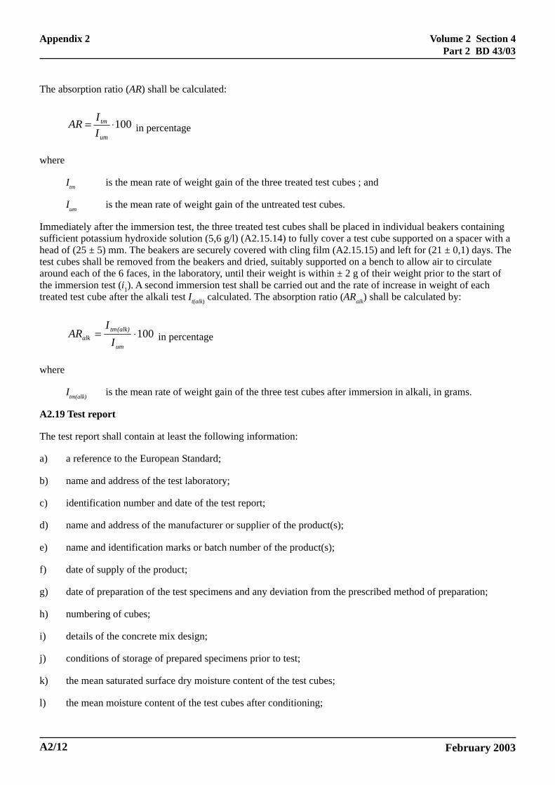
The absorption ratio (AR) shall be calculated:
100⋅=um
tm
IIAR in percentage
where
Itm is the mean rate of weight gain of the three treated test cubes ; and
Ium is the mean rate of weight gain of the untreated test cubes.
Immediately after the immersion test, the three treated test cubes shall be placed in individual beakers containingsufficient potassium hydroxide solution (5,6 g/l) (A2.15.14) to fully cover a test cube supported on a spacer with ahead of (25 ± 5) mm. The beakers are securely covered with cling film (A2.15.15) and left for (21 ± 0,1) days. Thetest cubes shall be removed from the beakers and dried, suitably supported on a bench to allow air to circulatearound each of the 6 faces, in the laboratory, until their weight is within ± 2 g of their weight prior to the start ofthe immersion test (i1). A second immersion test shall be carried out and the rate of increase in weight of eachtreated test cube after the alkali test It(alk) calculated. The absorption ratio (ARalk) shall be calculated by:
100⋅=um
(alk)tmalk I
IAR in percentage
where
Itm(alk) is the mean rate of weight gain of the three test cubes after immersion in alkali, in grams.
A2.19 Test report
The test report shall contain at least the following information:
a) a reference to the European Standard;
b) name and address of the test laboratory;
c) identification number and date of the test report;
d) name and address of the manufacturer or supplier of the product(s);
e) name and identification marks or batch number of the product(s);
f) date of supply of the product;
g) date of preparation of the test specimens and any deviation from the prescribed method of preparation;
h) numbering of cubes;
i) details of the concrete mix design;
j) conditions of storage of prepared specimens prior to test;
k) the mean saturated surface dry moisture content of the test cubes;
l) the mean moisture content of the test cubes after conditioning;
A2/12
Appendix 2
Volume 2 Section 4Part 2 BD 43/03
February 2003
m) the mean consumption of the impregnant;
n) the absorption ratio before and after exposure to alkali;
o) date of test and details of the test equipment used;
p) any deviation from the test method specified;
q) date of the report and signature;
r) any other observations.
A2.20 Requirements
In order for an impregnant to be acceptable for use on Highways Agency structures it must be tested on cubes fromtwo separate batches of concrete cast at different times and the mean result from the two batches must satisfy thecriteria given below:
Absorption Ratio AR <7.5%
Absorption Ratio after immersion in alkali AR(alk) <10%
Appendix 2
A2/13
Volume 2 Section 4Part 2 BD 43/03
February 2003
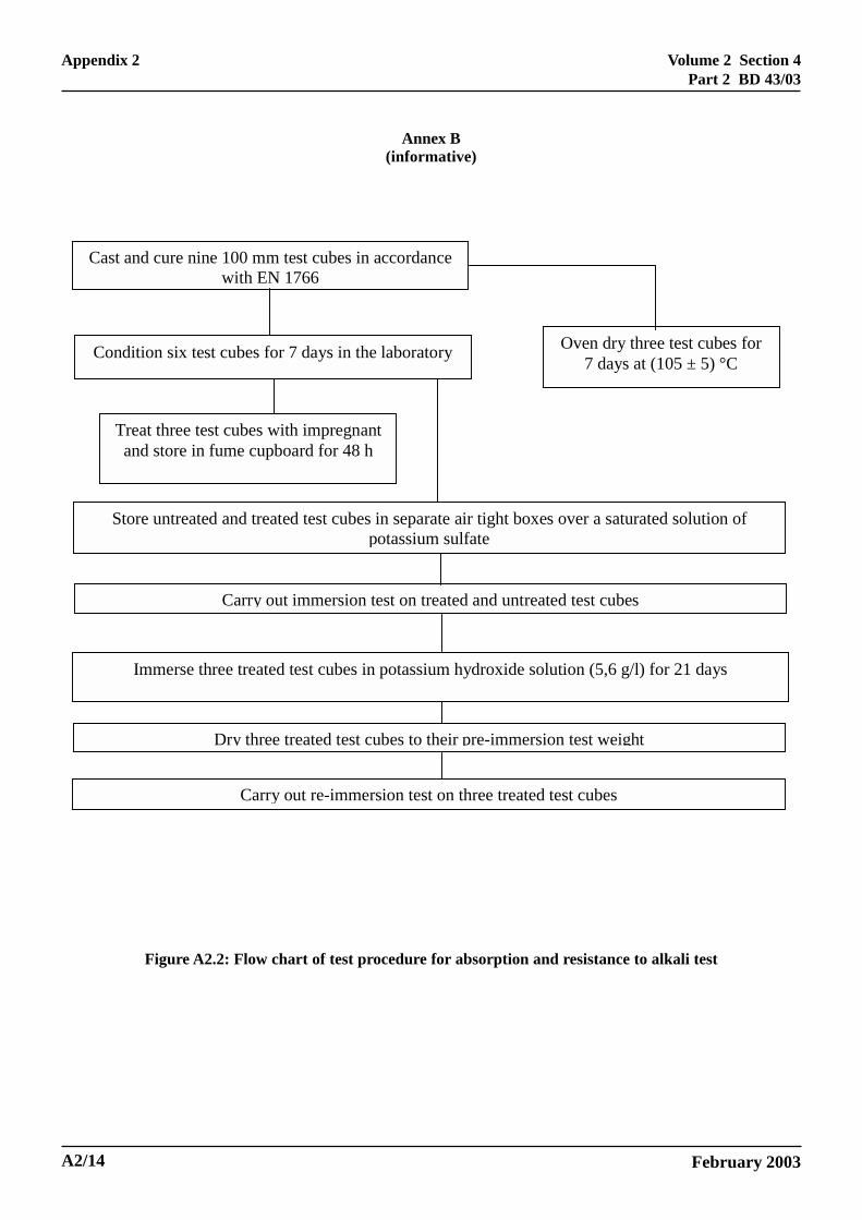
Annex B(informative)
Cast and cure nine 100 mm test cubes in accordance with EN 1766
Condition six test cubes for 7 days in the laboratory
Treat three test cubes with impregnant and store in fume cupboard for 48 h
Oven dry three test cubes for 7 days at (105 ± 5) °C
Carry out immersion test on treated and untreated test cubes
Store untreated and treated test cubes in separate air tight boxes over a saturated solution of potassium sulfate
Immerse three treated test cubes in potassium hydroxide solution (5,6 g/l) for 21 days
Dry three treated test cubes to their pre-immersion test weight
Carry out re-immersion test on three treated test cubes
Figure A2.2: Flow chart of test procedure for absorption and resistance to alkali test
A2/14
Appendix 2