VOLUME 2 HIGHWAY STRUCTURES DESIGN (SUBSTRUCTURES …
21
November 1994 DESIGN MANUAL FOR ROADS AND BRIDGES VOLUME 2 HIGHWAY STRUCTURES DESIGN (SUBSTRUCTURES AND SPECIAL STRUCTURES), MATERIALS SECTION 3 MATERIALS AND COMPONENTS PART 7 BA 26/94 EXPANSION JOINTS FOR USE IN HIGHWAY BRIDGE DECKS SUMMARY This Advice Note gives guidance on the selection and installation of expansion joints in highway bridge decks, together with advice on the commonly used type of joint. INTRODUCTION 1. Remove BA 26/88, which is superseded by this Advice Note, from Volume 2 Section 3 and archive as appropriate. 2. Insert BA 26/94 into Volume 2, Section 3. 3. Archive this sheet as appropriate. Note: A new contents page is available with BD 33/94.
Transcript of VOLUME 2 HIGHWAY STRUCTURES DESIGN (SUBSTRUCTURES …

November 1994
DESIGN MANUAL FOR ROADS AND BRIDGES
VOLUME 2 HIGHWAY STRUCTURESDESIGN (SUBSTRUCTURESAND SPECIALSTRUCTURES),MATERIALS
SECTION 3 MATERIALS ANDCOMPONENTS
PART 7
BA 26/94
EXPANSION JOINTS FOR USE INHIGHWAY BRIDGE DECKS
SUMMARY
This Advice Note gives guidance on the selection andinstallation of expansion joints in highway bridge decks,together with advice on the commonly used type of joint.
INTRODUCTION
1. Remove BA 26/88, which is superseded by thisAdvice Note, from Volume 2 Section 3 and archiveas appropriate.
2. Insert BA 26/94 into Volume 2, Section 3.
3. Archive this sheet as appropriate.
Note: A new contents page is available with BD 33/94.
Expansion Joints for Use inHighway Bridge Decks
Summary: This Advice Note gives guidance on the selection and installation ofexpansion joints in highway bridge decks, together with advice on thecommonly used type of joint.
THE HIGHWAYS AGENCY BA 26/94
THE SCOTTISH OFFICE DEVELOPMENT DEPARTMENT
THE WELSH OFFICEY SWYDDFA GYMREIG
THE DEPARTMENT OF THE ENVIRONMENTFOR NORTHERN IRELAND

Volume 2 Section 3Part 7 BA 26/94 Registration of Amendments
ELECTRONIC COPY - NOT FOR USE OUTSIDE THE AGENCY
November 1994 PAPER COPIES OF THIS ELECTRONIC DOCUMENT ARE UNCONTROLLED
REGISTRATION OF AMENDMENTS
Amend Page No Signature & Date of Amend Page No Signature & Date ofNo incorporation of No incorporation of
amendments amendments

Volume 2 Section 3Registration of Amendments Part 7 BA 26/94
ELECTRONIC COPY - NOT FOR USE OUTSIDE THE AGENCY
PAPER COPIES OF THIS ELECTRONIC DOCUMENT ARE UNCONTROLLED November 1994
REGISTRATION OF AMENDMENTS
Amend Page No Signature & Date of Amend Page No Signature & Date ofNo incorporation of No incorporation of
amendments amendments

DESIGN MANUAL FOR ROADS AND BRIDGES
ELECTRONIC COPY - NOT FOR USE OUTSIDE THE AGENCY
November 1994 PAPER COPIES OF THIS ELECTRONIC DOCUMENT ARE UNCONTROLLED
VOLUME 2 HIGHWAYSSTRUCUTRES: DESIGN(SUBSTRUCTURES ANDSPECIAL STRUCTURES),MATERIALS
SECTION 3 MATERIALS ANDCOMPONENTS
PART 7
BA 26/94
EXPANSION JOINTS FOR USE INHIGHWAY BRIDGE DECKS
Contents
Chapter
1. Introduction
2. Description of Joints and Fillers
3. Sealing of Gaps
4. Joint Type Options
5. Drainage
6. Installation
7. Inspection and Maintenance
8. References
9. Enquiries

Volume 2 Section 3 Chapter 1Part 7 BA 26/94 Introduction
1. INTRODUCTION
ssecifiedthes
f
nt
e
,
s
1.1 This Advice Note provides general informationon the selection and installation of various types of joand should be read in conjunction with BD 33 (DMRB2.3.6).
1.2 Except where a standard specified in this documimplements or is technically equivalent to a HarmonisEuropean Standard adopted for use within the EuropEconomic Area after 31 December 1985, anyrequirements for products or materials to comply withthe specified standard shall be satisfied by compliancwith
i. a relevant standard or code of practice a national standards institution orequivalent body of any member state ofthe European Economic Area
or ii. a relevant international standardrecognised in any member state of theEuropean Economic Area
or iii. a relevant specification acknowledgedfor use as a standard by a publicauthority of any member state of the European Economic Area
or iv. traditional procedures of manufacture oa member state of the EuropeanEconomic Area where these are thesubject of a written technical descriptionsufficiently detailed to permit assessmeof the goods or materials for the usespecified
or v. a European Technical Approval (ETA)issued in accordance with theConstruction Products Directive 89/106/EEC (or, until procedures areavailable for the issue of ETAs, aspecification sufficiently detailed topermit assessment) for goods ormaterials of an innovative nature orsubject to innovative processes ofmanufacture and which fulfil the purposprovided for by the specified standard
provided that the proposed standard, code of practicetechnical specification, technical description, or ETA
ELECTRONIC COPY - NOT F
November 1994 PAPER COPIES OF THIS ELECTRON
provides in use levels of safety, suitability and fitneint for purpose equivalent to those required by the sp
standard in so far as they are not inconsistent with "Essential Requirements" of the Construction Product
entedean
e
of
Directive 89/106/EEC.
Scope
1.3 This document is advisory in nature and amplifiemany of the principles and methods given in BD 33(DMRB 2.3.6). It gives guidance on the selection andinstallation of the most commonly used bridge deckexpansion joints including buried, asphaltic plug,nosing, elastomeric and cantilever type joints.
OR USE OUTSIDE THE AGENCY
IC DOCUMENT ARE UNCONTROLLED 1/1

Volume 2 Section 3 Chapter 2Part 7 BA 26/94 Description of Joints and Fillers
2. DESCRIPTION OF JOINTS AND FILLERS
ill theedge ofing
s
g
or
s
fit
e).
Buried
2.1 One or more components may be used to formthe joint below the surfacing. Materials range fromelastomeric pads to proprietary flashings which suppthe surfacing above the deck joint gap (see figure 1).
Asphaltic Plug
2.2 There are a number of proprietary joint systemincluded in this description. The joint is normallyconstructed in layers using a mixture of flexiblematerial and aggregate to provide not only thehomogeneous expansion medium but also the runninsurface at carriageway level (see figure 2).
Nosing
2.3 Materials which have been used to form in-situnosings include: steel plates or angle sections boltedanchored to the deck and epoxy mortar. Nosingsnowadays are generally formed using cementitious,polyurethane or polyureide binders (see figure 3).
Reinforced Elastomeric
2.4 These joints are prefabricated units which spanthe deck joint gap and are either an elastomer orelastomer reinforced with metal plates. Different sizeare available to suit various movement ranges (seefigure 4).
Elastomeric in Metal Runners
2.5 There are a number of proprietary joints whichinto this category, either in a single element or multi-element form. A single element joint consists of anelastomeric seal fitted between two metal runners, onfixed to each side of the deck joint gap (see figure 10An example of a multi-element joint is shown in figure5.
Cantilever Comb or Tooth Joints
2.6 These are pairs of mating toothed metal platesindividually bolted to each side of the deck joint gap.They can either be a proprietary system or purposemade for a specific installation (see figure 6).
ELECTRONIC COPY - NOT F
November 1994 PAPER COPIES OF THIS ELECTRON
Transition Strip
2.7 Bituminous or resinous material used to fspace between a prefabricated joint and the cut
ort the surfacing to form a smooth continuous runnsurface.
OR USE OUTSIDE THE AGENCY
IC DOCUMENT ARE UNCONTROLLED 2/1

Surfacing
Flexiblefiller
Flashing Deck joint gap
Elastomericpad
DeckWaterproofing
Protective layer
FIGURE 1 - BURIED
FIGURE 2 - ASPHALTIC PLUG
SurfacingProtectivelayer
Flexiblematerial
DeckWaterproofingPlate
FIGURE 3 - NOSING
Surfacing
Protectivelayer
Nosingmaterial
DeckWaterproofingCompression
seal
Chapter 2 Volume 2 Section 3Description of Joints and Fillers Part 7 BA 26/94
ELECTRONIC COPY - NOT FOR USE OUTSIDE THE AGENCY
PAPER COPIES OF THIS ELECTRONIC DOCUMENT ARE UNCONTROLLED November 19942/2
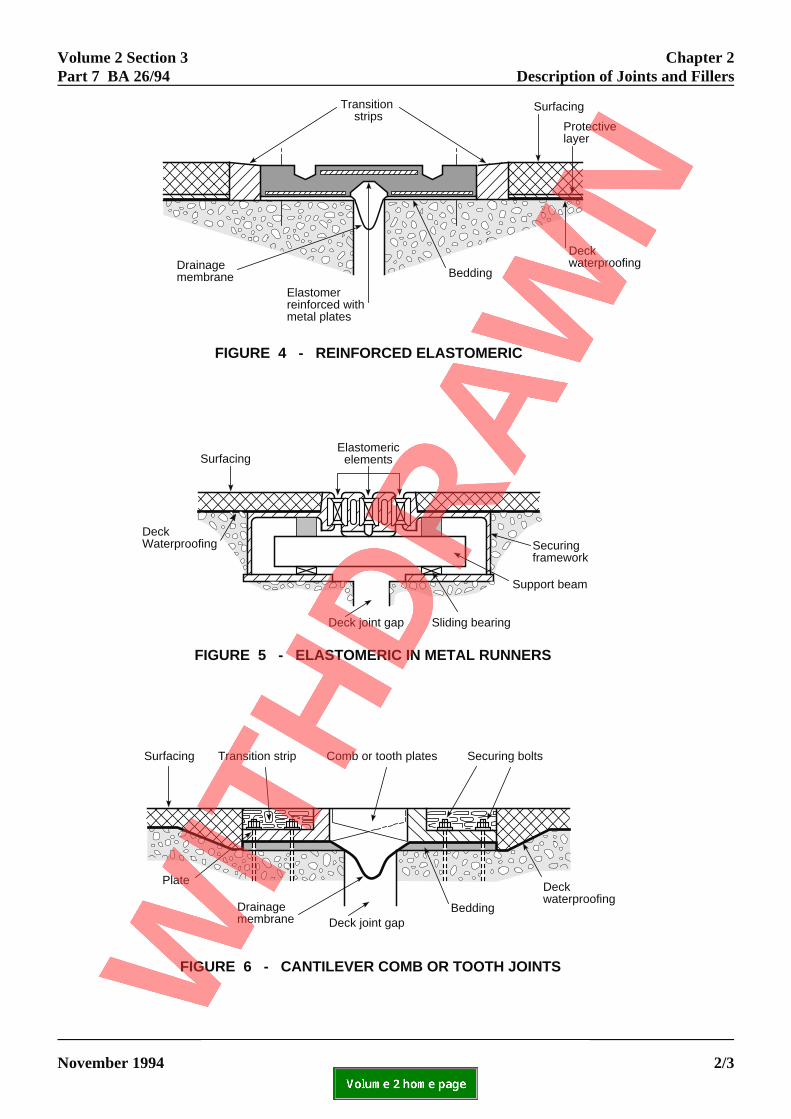
FIGURE 4 - REINFORCED ELASTOMERIC
Surfacing
Protectivelayer
Transition strips
DeckwaterproofingDrainage
membrane Bedding
Elastomerreinforced withmetal plates
FIGURE 5 - ELASTOMERIC IN METAL RUNNERS
SurfacingElastomeric
elements
DeckWaterproofing Securing
framework
Support beam
Deck joint gap Sliding bearing
Surfacing Transition strip Comb or tooth plates Securing bolts
Bedding
Deckwaterproofing
Deck joint gapDrainage membrane
Plate
FIGURE 6 - CANTILEVER COMB OR TOOTH JOINTS
Volume 2 Section 3 Chapter 2Part 7 BA 26/94 Description of Joints and Fillers
ELECTRONIC COPY - NOT FOR USE OUTSIDE THE AGENCY
November 1994 PAPER COPIES OF THIS ELECTRONIC DOCUMENT ARE UNCONTROLLED 2/3

Volume 2 Section 3 Chapter 3Part 7 BA 26/94 Sealing of Gaps
ELECTRONIC COPY - NOT FOR USE OUTSIDE THE AGENCY
November 1994 PAPER COPIES OF THIS ELECTRONIC DOCUMENT ARE UNCONTROLLED 3/1
3. SEALING OF GAPS
3.1 Joints with grooves or gaps at surface level mayform a hazard to pedestrians and all such joints infootways should be provided with cover plates. Similarly grooves and gaps orientated generally in thedirection of traffic flow such as can occur with combjoints or heavily skewed joints may form a hazard tocyclists and such installations may require cover platesin the carriageway or depending on the type of joint acompressible insert can be installed to reduce the gapsize at surface level.
3.2 Normally 12 mm thick steel cover plates aresufficiently stiff for most carriageway applications anddo not interfere with ride quality. In footways, althoughthinner plates could be used, it is advisable to use thesame thickness in order to withstand any accidentalwheel loading. The joint itself may need to be set lowerin the footway to accommodate the thickness of anycover plate needed.
3.3 Where compression seals, sealant and filler boardmaterials are used their compressibility may transmitsignificant forces across the gap. The compressibilty ofthe material used in this situation should therefore betaken into account at the design stage.

Volume 2 Section 3 Chapter 4Part 7 BA 26/94 Joint Type Options
4. JOINT TYPE OPTIONS
ed toeeting,aterials
g on thehe
t
rld
e
ne
d
inort
is
0-f
nd
ithas
e
ts is
g
General
4.1 Joints should be installed which willaccommodate all the vertical and horizontal movemelikely to be encountered in service. The various typeof joint for different ranges of movement are shown iTable 1 in BD 33 (DMRB 2.3.6). However more thanone type of joint may be suitable for a particularmovement range or site location and other factors hato be considered before the final choice of joint is maSee clause 4.4.
Transition Strips
4.2 Where a joint system requires a transition strip, width of the strip should be kept as narrow as possibideally 50-100 mm wide (see figure 4) with the edgethe strip adjacent to the joint chamfered to assist in tdissipation of wheel impact loads. Premature failureof proprietary joints are often associated with unsuitatransition strips which have themselves failed. Whecementitious materials are used, consideration shougiven to the provision of anti-crack reinforcement tieinto the deck.
Very Large Movements
4.3 Specific advice on the design of expansion jointo accommodate movement greater than that providfor by proprietary joint systems is not given in thisdocument, although the basic principles still apply.
Proprietary Joint
4.4 Guidance given in the following sub-clauses othe selection of joints is based on information obtainfrom site inspections, surveys and feedback fromvarious sources. The information compiled has showthat most types of joint perform satisfactorily provide
i. The total joint system is designed towithstand the effects of traffic loading includingimpact and abrasion.
ii. The total movement at the deck joint gais within the capacity of the joint system.
iii. The joint is installed by a competentcontractor familiar with the system.
ELECTRONIC COPY - NOT F
November 1994 PAPER COPIES OF THIS ELECTRO
nn,
ntsn
4.5 In the past various materials have been usform buried joints eg copper lined bituminous sh
ve quarry tiles, formica or steel plates. All these mde. have had varying degrees of success dependin
horizontal movements and traffic loads imposed. T
hele,ofhesbleed be
tsd
d
n:
p
Key factors affecting the choice of a joint are shown Table 1, which has been reproduced from TRRL repLR1104.
Buried Joints
principal problem where rigid plates have been usedthat they are difficult to bed down properly andsubsequent rocking under traffic loading has been amajor cause of premature failure of the joint system.
4.6 For movements up to 10 mm a proprietaryflashing may be appropriate provided there is aminimum of 100 mm surfacing. For movements of 120 mm an elastomeric pad may be installed on top othe flashing to support surfacing 500-600 mm wide. When laid as part of the joint this improves itsflexibility and hence durability.
Asphaltic Plug
4.7 This system was developed during the 1970s awas used initially to cater for small movements. However, although the system coped successfully wthese movements in some cases the joint material wtoo flexible and suffered from tracking and flowingespecially during hot weather. The system wasimproved by increasing the density and stiffness of thmaterial, mainly in the top layers up to carriagewaylevel.
In general asphaltic plug joints are now formulated towork satisfactorily in the movement range given inTable 1 of BD 33 (DMRB 2.3.6) provided the adjacensurfacing is not less than 100 mm thick, the gradientand crossfalls are not too severe and the bridge decknot noticeably lively at the joints. It is difficult todefine limits for the latter two but generally wherepremature failure has occurred one or both of thesefactors have been present.
On significant gradients the joint should be formedusing a stiffer binder to reduce debonding and bulgincaused by binder flow. These joints are normallyinstalled at a nominal 500mm width but, depending othe condition of the surfacing at the time of installatiojoints as wide as 800mm or 1m have been installed.
OR USE OUTSIDE THE AGENCY
NIC DOCUMENT ARE UNCONTROLLED 4/1

Chapter 4 Volume 2 Section 3Joint Type Options Part 7 BA 26/94
.
re are castowever
y e
s thet RB
tesorm
thethed
ly onh th may BD
e alurepsehas
rcesr, eg
ked if
seatthe
r
Where possible joints of this width should be avoided
Nosings
4.8 Steel plates or angle sections, bolted or anchoto the deck, were at one time commonly used to formprotective nosings but are seldom used today. Epoxmortar nosings were first used in 1964, for thereplacement of faulty steel nosings, and were the mowidely used type of joint in the early 1970s but did noperform as well as first anticipated. A number offactors influenced the performance including nosingdesign, materials and bad workmanship.
In spite of improvements in the formulations of epoxynosings, which increased their success, they have besuperseded to some extent by cementitious,polyurethane and polyureide binders, which are moretolerant of adverse site conditions and have a bettersuccess rate in service.
Reinforced Elastomeric
4.9 This joint comes in various forms from differentmanufacturers and is supplied in a range of sizes. It been used for many years with a good success rate. larger sizes of elastomeric type joints tend to createmore noise than normal under traffic but this is onlyusually a problem when the installation is adjacent toresidential property. Some manufacturers can providspecial attachment to reduce the noise problem. Faiof this type of joint has been from failed transition stri(see clause 4.2) and splitting or excessive wear of thrubber and subsequent exposure of the metal plates occurred in a few cases. Failure by exposure of themetal plates has also been recorded where lateral fohave caused accelerated wear of the covering rubbeat exits from roundabouts. Elastomeric joints arenormally supplied in unit lengths and fixed to the decusing bolts or resin anchors. Where possible tensioncast in bolts should be used to anchor these joints orsite drilled installations are used the holes should beunder-reamed prior to fixing of the bolts. In either caan adequate length of bolt should be debonded so thany relaxation over the bolt length does not result in complete loss of tension in the bolts. Resistance towater penetration can be improved by ensuring thateither the joint is manufactured and supplied in onecontinuous length or the units are vulcanised togetheon site to form one continuous length.
ELECTRONIC COPY - NOT FO
PAPER COPIES OF THIS ELECTRON4/2
d element in a range of sizes. Generally the joints in using formed recesses in the deck concrete. Hdepending on the type of joint used, fixings can b
similar to those used in elastomeric joints or event bonded to the deck concrete. In consideration of
requirements of paragraph 3.13 from BD 33/94 (DM2.3.6) elastomeric seals are generally of two distinctypes, those which are non-load bearing membranlocated below carriageway level and those which f
adhesive should be applied to the locating ears of en seal which will assist installation and help resist
ingress of dirt, grit and water between the seal anmetal runners.
between the teeth can become very large, especialas skew bridges decks and the orientation of the tee
The also be significant in certain circumstances (see33/94 paragraph 3.16. DMRB 2.3.6).
Elastomeric in Metal Runners
4.10 This type of joint also comes in various formsfrom different manufacturers, either as single or multi-
load bearing seals at carriageway surface level. An
Cantilever Comb or Tooth Joints
4.11 These joints can either be purpose made for aparticular installation or be proprietary joints. The gaps
R USE OUTSIDE THE AGENCY
IC DOCUMENT ARE UNCONTROLLED November 1994

Volum
e 2 Section 3
Chapter 4
Part 7 B
A 26/94
Joint Type O
ptions
ELE
CT
RO
NIC
CO
PY
- NO
T F
OR
US
E O
UT
SID
E T
HE
AG
EN
CY
Novem
ber 1994P
AP
ER
CO
PIE
S O
F T
HIS
ELE
CT
RO
NIC
DO
CU
ME
NT
AR
E U
NC
ON
TR
OLLE
D4/3
Joint
Type
Movements at the joint (mm) Traffic over joint
Joint
Design
Materials
Used
Condition
of
Substrate
Installation
temperature EC
In service
weathering
Detritus
and
corrosion
Site
preparation
and
workmanship
Bond
and
anchorage
Thermal Dynamic Frequency/
Lane/Hour
Axle loads (k/N)
Horizontal Horizontal Vertical
0-15 15-50 50+ <0.05 0.05-0.10 >0.10 <2 2-4 >4 <10 10-50 >50 <10 10-40 >40 <10 10-15 >15
Buried M H N/A L M H L M H L M H L M H M-H M-H M-H L M H M-H L H M
Asphaltic
Plug
L M N/A L L L L L M L** L** M** L** L** M** L-M M M L L M L L M L
Nosing
(with
sealant)
M H N/A L L M L L M L M H L M H H H H L M H L-M L-M H H
Reinforced
Elastomeric
L* L* L* L L M L L M M M H L L M M-H L-M M-H L L L L M-H H H
Elastomeric
in Metal
Runners
L L L L L L L L L L L M L L L M-H M N/A L L L L M M H
Comb or
Tooth
Joints
L* L* L* L L M L L M L L M L L M M-H L-M M-H L L L L H M H
TransitionStrip
L L L L L M L L M L M H L M H M M-H H L M H L L-M H H
* Assuming joint in correct design range ** Assuming correct binder type N/A = Not applicable
L = Low ) M = Moderate ) effect on performance H = High )
Note: This table is based on a similar table from TRRL Report LR1104, but has been modified and takes into account current information on joint performance

Volume 2 Section 3 Chapter 5Part 7 BA 26/94 Drainage
5. DRAINAGE
un
ulhisndm
hat
e
d
be
geuldt the
nlyre
dit
ero
Seals
5.1 Where seals of the type described in BD 33clause 3.8 (DMRB 2.3.6) are installed these should bwatertight. Seals will also assist in the exclusion of gand dirt which would otherwise find its way into thejoint drainage system. An additional membrane shoalso be incorporated with certain joint types as showFigures 4 and 6.
Sub-surface Drainage
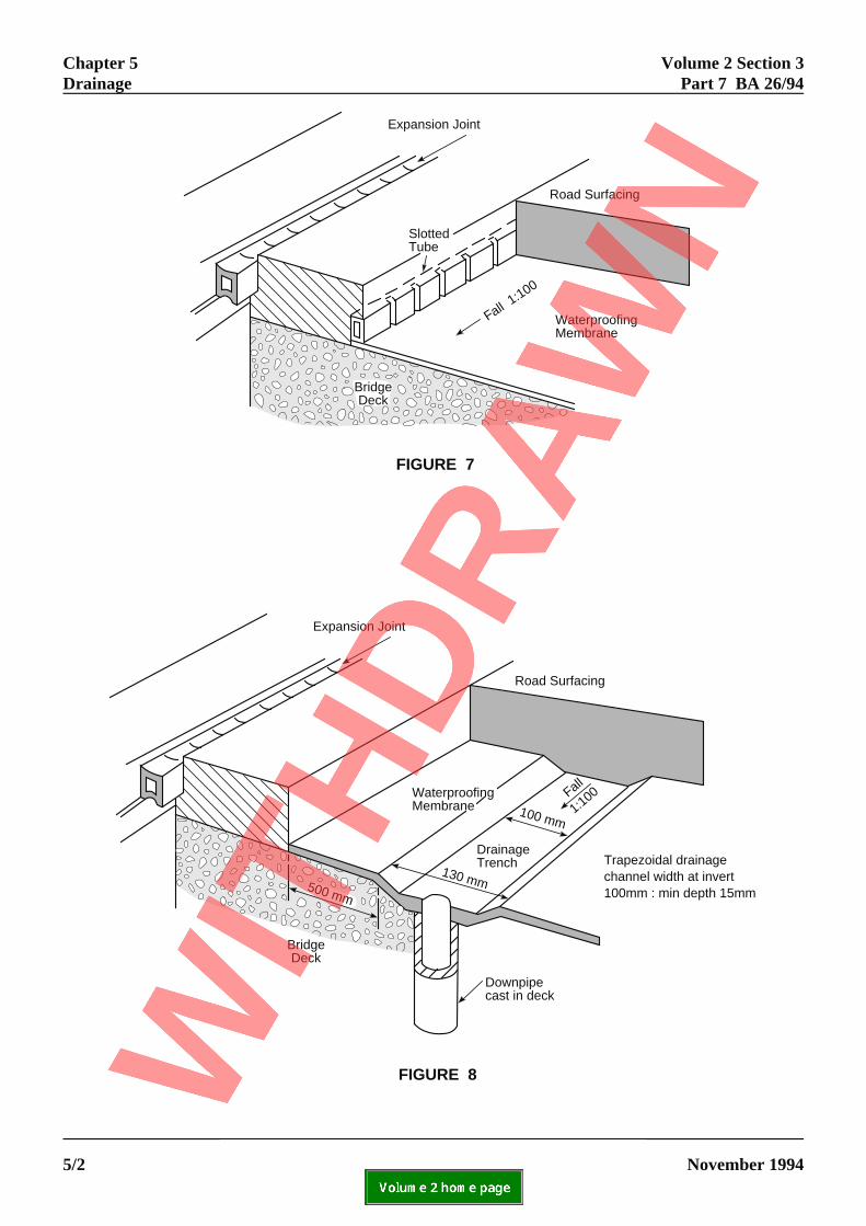
5.2 Water trapped within the road surfacing on thehigh side of a deck joint can, through hydraulic pressfrom wheel loading, cause failure of the bond or seabetween the joint and the waterproofing systems. Tmay result in water leakage into the deck joint gap ahence into the adjacent concrete. To prevent this frooccurring a transverse and through deck sub-surfacedrainage system may be provided, as illustrated inFigures 7 and 8, which illustrate some of the forms tsub-surface drainage may take. Although in-situnosings have been illustrated the drainage details areasily adapted for different types of joint.
5.3 Fig 7 is typical of current practice in France anGermany and certain UK systems. The buriedgalvanised steel or aluminium slotted drain tube mayeither circular or rectangular in cross section anddischarge water via a suitable connection to the briddrainage system. Transverse drainage systems shobe as large as possible,located in such a manner thaflow area is not interrupted and detailed to permitjetting through of the drainage tubes.
Longitudinal drainage systems have been used, maiwith Asphaltic Plug Joints, where longitudinal pipes alaid across the width of the joint providing a pressurerelief system from one side of the joint to the other.
ELECTRONIC COPY - NOT FO
November 1994 PAPER COPIES OF THIS ELECTRON
erit
ld in
re
5.4 Fig 8 shows another detail developed in Italy. The down pipes are spaced at intervals to suit thebearing and jacking point positions. The trough is fillewith surfacing which is sufficiently permeable to permthe passage of water. The pipes should be carefullypositioned in order that drips from the outlets do notdamage the face of adjacent concrete. Through deckdrainage should be installed at the low points in thedeck and the deck surface adjacent to the joint shouldbe cast with a backfall to ensure that sub-surface watdrains towards the cast in pipes. For advice relating tthe waterproofing and drainage of bridge decksreference should be made to BA 47 (DMRB 2.3.5).
R USE OUTSIDE THE AGENCY
IC DOCUMENT ARE UNCONTROLLED 5/1
Expansion Joint
FIGURE 7
Road Surfacing
WaterproofingMembrane
Fall 1:100
SlottedTube
BridgeDeck
Expansion Joint
FIGURE 8
Road Surfacing
BridgeDeck
Downpipecast in deck
500 mm
130 mm
100 mm
DrainageTrench
WaterproofingMembrane
Trapezoidal drainagechannel width at invert100mm : min depth 15mm
Fall
1:100
Chapter 5 Volume 2 Section 3Drainage Part 7 BA 26/94
ELECTRONIC COPY - NOT FOR USE OUTSIDE THE AGENCY
PAPER COPIES OF THIS ELECTRONIC DOCUMENT ARE UNCONTROLLED November 19945/2

Volume 2 Section 3 Chapter 6Part 7 BA 26/94 Installation
ELECTRONIC COPY - NOT FOR USE OUTSIDE THE AGENCY
November 1994 PAPER COPIES OF THIS ELECTRONIC DOCUMENT ARE UNCONTROLLED 6/1
6. INSTALLATION
Fixing of Joints
6.1 Joints are fixed to the deck concrete by one of thefollowing means:
i. Bondii. Bolts or resin anchored studsiii. Anchor bars.
For methods i. and ii. the deck joint gap andwaterproofing are normally covered either withhardboard or thin plywood over a width equal to that ofthe joint installation and the surfacing then laidcontinuously over the top. The required width ofsurfacing is subsequently sawn and removed to the topsurface of the waterproofing system. Thewaterproofing is then carefully cut back to expose theconcrete surface which should be prepared to receivethe expansion joint system (see figure 9). It is veryimportant that deck waterproofing is carefully detailedin the vicinity of the joint to ensure the continuity of thewaterbarrier, eg either by bond or lap. For method iii.the joint system is installed before the surfacing is laid. The joint anchor bars lapping or interlocking with thedeck reinforcement are cast into boxed out recesses inthe concrete deck using small aggregate concrete. When the concrete has cured the surfacing is normallylaid to within 15-20 mm of the metal edge of the joint. This 15-20 mm groove is then filled with bitumasticmaterial (see figure 10).
6.2 The installation procedures in clause 6.1 aregeneral descriptions and are not intended to representany particular type of joint system. For the procedureapplicable to a specific system, reference should bemade to the relevant manufacturer's installationinstructions. However in all cases the requirements ofBD 33 (DMRB 2.3.6) must be satisfied.

FIGURE 9 - TYPICAL INSTALLATION PROCEDURE(i) Bond(ii) Bolts or resin anchored studs
2. Surfacing laid over joint.
Masking stripDeck Waterproofing
Protective layerSurfacing
4. Surfacing and masking strip removed and exposed concrete prepared and cleaned. Sawn edges primed with waterproof sealer.
Sawn edges sealed
1. Expansion gap covered with masking strip (hardboard or plywood) with wood fillet engaging in expansion gap with sufficient clearance to allow for thermal movements.
Masking strip
Deck joint gap
Deck Waterproofing
Width of joint
3. Saw cut each side of masking strip.
Masking strip
Saw cuts
5a. For a bonded system the joint material can now be installed.
5b. For a system using bolts or resin anchored studs their position has to be marked and holes drilled before the joint is installed.
Asphaltic Plug
Elastomeric
Reference should always be made to therelevant manufacturers installationinstructions.
NOTE :
Chapter 6 Volume 2 Section 3Installation Part 7 BA 26/94
ELECTRONIC COPY - NOT FOR USE OUTSIDE THE AGENCY
PAPER COPIES OF THIS ELECTRONIC DOCUMENT ARE UNCONTROLLED November 19946/2
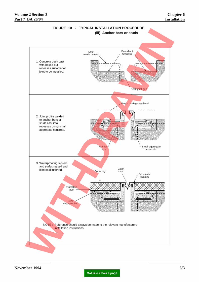
1. Concrete deck cast with boxed out recesses suitable for joint to be installed.
Boxed outrecesses
FIGURE 10 - TYPICAL INSTALLATION PROCEDURE(iii) Anchor bars or studs
2. Joint profile welded to anchor bars or studs cast into recesses using small aggregate concrete.
3. Waterproofing system and surfacing laid and joint seal inserted.
Reference should always be made to the relevant manufacturersinstallation instructions
NOTE :
Deckreinforcement
Deck joint gap
Anchorbars
Small aggregateconcrete
Finish carriageway level
Jointseal
Bitumasticsealant
Surfacing
Protectivelayer
Deckwaterproofing
Volume 2 Section 3 Chapter 6Part 7 BA 26/94 Installation
ELECTRONIC COPY - NOT FOR USE OUTSIDE THE AGENCY
November 1994 PAPER COPIES OF THIS ELECTRONIC DOCUMENT ARE UNCONTROLLED 6/3

Volume 2 Section 3 Chapter 7Part 7 BA 26/94 Inspection and Maintenance
ELECTRONIC COPY - NOT FOR USE OUTSIDE THE AGENCY
November 1994 PAPER COPIES OF THIS ELECTRONIC DOCUMENT ARE UNCONTROLLED 7/1
7. INSPECTION AND MAINTENANCE
7.1 Failure of an expansion joint can create a serioushazard for traffic therefore it is strongly recommendedthat expansion joints are regularly inspected to ensurethat they continue to operate in accordance with all therequirements of BD 33 (DMRB 2.3.6).
7.2 An expansion joint will not usually have the samelength of working life as the bridge itself. Indeed manyof the materials used in certain types of joint are knownto have much shorter lives and such items as splitcompression seals or detached sealants will needreplacement, asphaltic plug joints may need levelling-up and elastomeric joints may need partial replacementor resetting. These operations can usually be carriedout quickly during off-peak periods of traffic flow.
7.3 It is important also that faults such as blockeddrainage or silted-up gaps are detected at an early stagesince water leakage containing chlorides can have verydamaging effects of reinforced concrete or steelelements in the bridge structure. Silted up gaps canpermit the transmission of high forces into the jointfixing system.
7.4 Replacement of expansion joints is relatively veryexpensive because of the substantial costs of trafficmanagement and the indirect costs of traffic delayswhich are additional to the costs of merely replacing thejoint. Therefore when carriageway resurfacingoperations are planned, any bridge joints which areaffected should be examined carefully so that ifnecessary they can be replaced at the same time. Insome cases it may be preferable to replace joints beforethey have reached the end of their useful lives if thework can be combined with other maintenanceactivities.

Volume 2 Section 3 Chapter 8Part 7 BA 26/94 References
ELECTRONIC COPY - NOT FOR USE OUTSIDE THE AGENCY
November 1994 PAPER COPIES OF THIS ELECTRONIC DOCUMENT ARE UNCONTROLLED 8/1
8. REFERENCES
1. Design Manual for Roads and Bridges (DMRB)
Volume 2: Section 3 Materials and Components
BD 33 Expansion Joints for Use in HighwayBridge Decks (DMRB 2.3.6)
BA 47 Waterproofing and Surfacing of ConcreteBridge Deck (DMRB 2.3.5)
2. LR 1104. The performance in service of bridgedeck expansion joints. A R Price. TRRL.

Volume 2 Section 3 Chapter 9Part 7 BA 26/94 Enquiries
ELECTRONIC COPY - NOT FOR USE OUTSIDE THE AGENCY
November 1994 PAPER COPIES OF THIS ELECTRONIC DOCUMENT ARE UNCONTROLLED 9/1
9. ENQUIRIES
All technical enquiries or comments on this Advice Note should be sent in writing as appropriate to:-
Head of Bridges Engineering DivisionThe Highways AgencySt Christopher HouseSouthwark Street A J PICKETTLondon SE1 0TE Head of Bridges
Engineering Division
The Deputy Chief EngineerThe Scottish Office Industry DepartmentRoads DirectorateNew St Andrew's House J INNESEdinburgh EH1 3TG Deputy Chief Engineer
Head of Roads Engineering (Construction) DivisionWelsh OfficeY Swyddfa GymreigGovernment BuildingsTy Glas Road B H HAWKERLlanishen Head of Roads EngineeringCardiff CF4 5PL (Construction) Division
Assistant Chief Engineer (Works)Department of the Environment for Northern IrelandRoads Service HeadquartersClarence Court10-18 Adelaide Street D O'HAGANBelfast BT2 8GB Assistant Chief Engineer (Works)