
DM3MECH Mechanical Hot Tapping Machine Operator’s Manual
8
DM3MECH Mechanical Hot Tapping Machine Operator’s Manual Shown: DM3MECH #08350 1019-58350 REED MANUFACTURING COMPANY 1425 West Eighth St. Erie, PA 16502 USA Phone: 800-666-3691 or 814-452-3691 Fax: 800-456-1697 or 814-455-1697 www.reedmfgco.com
Transcript of DM3MECH Mechanical Hot Tapping Machine Operator’s Manual

1
Mechanical Hot Tapping Machine Operator’s Manual
DM3MECHMechanical Hot Tapping MachineOperator’s Manual
Shown: DM3MECH#08350
1019-58350
REED MANUFACTURING COMPANY
1425 West Eighth St. Erie, PA 16502 USA Phone: 800-666-3691 or 814-452-3691 Fax: 800-456-1697 or 814-455-1697
www.reedmfgco.com
2
Mechanical Hot Tapping Machine Operator’s Manual
CAUTION:When used on a pressurized system an outward force on the shaft will occur as the drill bit passes through wall of the pipe. Forces can be as high as 45 lbs on a system pressurized at 300 psi. At any time after the drill bit passes through wall of the pipe a reactive force must be applied to the end of the shaft until the shaft is in the fully retracted position, failure to do so my cause damage to the tool or personal injury. Applying too much force while cutting the coupon can result in a sudden breakthrough of the hole saw. A sudden break through may result in the coupon retaining drill bit striking the back side of the main and damaging the drill bit. One can prevent this by cutting a spacer of 3/4” copper tube long enough to stop the drill bit from hitting the back of the main. Slip this spacer over the exposed shaft between the gland nut and the drill chuck.
Note: Use standard depth holes only.Store shafts separate from hole saws. Allowing the hole saw teeth to contact the shaft during transportation and storage can damage the shaft. A damaged shaft can damage the Main Body and cause the shaft to seize during use.
Description: REED DM3MECH makes branch connections from 3/4” to 4” valve size on any appropriately sized mainline for most piping materials up to 300 psi. The machine eliminates the need to shut-down, drain, cut, re-fit and refill piping systems.See www.reedmfgco.com for a list of items included with the purchase of REED #08350 and #08351.
Specifications:Valve Size: 3/4” to 4”Pipe Materials: Black Iron, Steel, Galvanized, Copper, Brass and PVCMaximum Pressure: Chilled water and hot water systems: 300 psi Steam: 15 psiMaximum Operating Water Temperature 250 degrees FDo not use DM3MECH on ammonia or any other caustic systems.
Accessories (Required but not supplied)
1. Correctly sized saddle (or threadolet).
2. Branch size shoulder nipple.
3. Branch sized full bore gate valve (or full bore ball valve).
4. Branch sized nipple long enough for drill bit to clear valve when fully retracted.
5. Branch size or 1 1/4” NPT “T” and appropriate reducer bushings. (Labeled as Bleed-Off “T”, Figure 1.)
6. Valve or hose bib, and appropriate pipe nipple and reducer bushings. (Labeled as Bleed-off Valve, Figure 1.)
7. 3/8” or 1/2” Drill Motor.
8. Hose (if flushing chips or filings away).
Additional Accessories for 3” and 4” Flanged Valves.
A. Fabricated pipe saddle and flange (4 1/2” throat of saddle to face of flange).
B. Branch size threaded flange.
C. Branch size by 1 1/4” bushing.
D. 1 1/4” by close nipple.
E. 1 1/4” by 1 1/4” by 1 1/4” “T”.
F. 1 1/4” to 1/2” bushing.
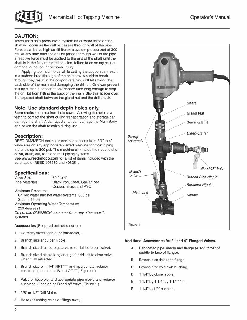
Shaft
Gland Nut
Sealing Unit
Bleed-Off “T”
Bleed-Off ValveBranch Valve
Shoulder Nipple
SaddleMain Line
BoringAssembly
Branch Size Nipple

3
Mechanical Hot Tapping Machine Operator’s Manual
Operation (NOT using a flanged valve):Verify all equipment is in good condition. Use only fittings, nipples and valves pressure rated for the job. Electrical tools and exten-sion cords must comply with OSHA rules. Using a ground fault interrupter increases operator safety when using electric power tools around water and other fluids.
1. Bolt saddle fitting on mainline. Or, weld a threadolet onto the mainline.
2. Select the proper size hole saw. Verify the hole saw clears the gate valve bore adequately. Inadequate clearance can result in damage should the hole saw contact the valve while sawing.
3. Install shoulder nipple and Branch Valve onto the fitting (or threadolet).
4. Select the appropriate shaft.
A. For 5/8” to 1 1/8” hole saws, screw directly to the 18” shaft (no arbor).
B. For 1 3/8” to 3 1/4” hole saws, use the #43514 Arbor on the 24” shaft.
5. Install Hole Saw. A. 5/8” to 1 1/8” Hole Saws screw directly to the 18” shaft.
B. 1 3/8” to 3 1/4” Hole Saw - insert arbor into the 24” shaft, tighten set screws. Screw the hole saw on to the end of the arbor, align barrel pins with holes on hole saw and turn the upper diameter of the arbor to engage barrel pins.
6. Install coupon retaining drill bit. The end of the wire must extend past the end of the hole saw to retain the coupon. Align the flats on the bit with the set screw and tighten. See Figure 5 to set coupon retaining drill bit.
7. Assemble appropriate bleed-off “T” and branch nipple to the Main Body. See Figures 1 and 2 for details.
8. A. Apply a thin layer of H1 grease to the shaft before and after use.
B. Loosen the gland nut and install the shaft gently. Use a twisting motion while pushing the shaft past the seal in the Main Body.
C. Tighten the gland nut until snug.
9. Assemble to the mainline the saddle, shoulder nipple, branch valve and any reducers needed.
10. Pull the shaft as far back as possible into the bleed-off “T”.
11. Attach the boring assembly to the gate valve. See Figure 1 for details.
12. Install the Bleed-off Valve onto the “T”.
13. Attach hose to Bleed-off Valve for flushing chips to drain (if desired).
14. Pressure test setup through the Bleed-off Valve.
15. Chuck shaft into drill motor. • MAKE SURE drill is set in non-hammer mode. • DO NOT USE impact type drills.
16. Drill until pilot drill penetrates the main line. Verify seals OK. One can hand tighten the Gland Nut should fluid leak past the Main Body at the shaft. Do not over tighten the Gland Nut. (See CAUTION on page 2.)
17. Resume drilling. Use moderate pressure until the hole saw penetrates the main completely. Reduce the pressure on the drill prior to break through. Reducing the pressure before break through reduces the likelihood of the drill bit and hole saw hitting the back side of the main.
18. Pull the drill and shaft back to the limit, shut the Branch Valve, open the Bleed Valve and then disconnect the Boring Assembly from the Branch Valve.
19. Loosen the Gland Nut and remove the shaft with a twisting motion. Grease the shaft to prevent rusting.
ShaftGland NutSealing UnitBleed-Off “T”
Bleed-Off ValveBranch Valve
Shoulder Nipple
SaddleMain Line
BoringAssembly
Branch Size Nipple
4
Mechanical Hot Tapping Machine Operator’s Manual
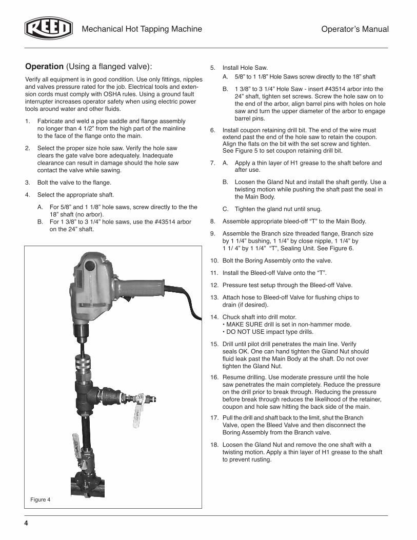
Operation (Using a flanged valve):Verify all equipment is in good condition. Use only fittings, nipples and valves pressure rated for the job. Electrical tools and exten-sion cords must comply with OSHA rules. Using a ground fault interrupter increases operator safety when using electric power tools around water and other fluids.
1. Fabricate and weld a pipe saddle and flange assembly no longer than 4 1/2” from the high part of the mainline to the face of the flange onto the main.
2. Select the proper size hole saw. Verify the hole saw clears the gate valve bore adequately. Inadequate clearance can result in damage should the hole saw contact the valve while sawing.
3. Bolt the valve to the flange.
4. Select the appropriate shaft.
A. For 5/8” and 1 1/8” hole saws, screw directly to the the 18” shaft (no arbor). B. For 1 3/8” to 3 1/4” hole saws, use the #43514 arbor on the 24” shaft.
5. Install Hole Saw. A. 5/8” to 1 1/8” Hole Saws screw directly to the 18” shaft
B. 1 3/8” to 3 1/4” Hole Saw - insert #43514 arbor into the 24” shaft, tighten set screws. Screw the hole saw on to the end of the arbor, align barrel pins with holes on hole saw and turn the upper diameter of the arbor to engage barrel pins.
6. Install coupon retaining drill bit. The end of the wire must extend past the end of the hole saw to retain the coupon. Align the flats on the bit with the set screw and tighten. See Figure 5 to set coupon retaining drill bit.
7. A. Apply a thin layer of H1 grease to the shaft before and after use.
B. Loosen the Gland Nut and install the shaft gently. Use a twisting motion while pushing the shaft past the seal in the Main Body.
C. Tighten the gland nut until snug.
8. Assemble appropriate bleed-off “T” to the Main Body.
9. Assemble the Branch size threaded flange, Branch size by 1 1/4” bushing, 1 1/4” by close nipple, 1 1/4” by 1 1/ 4” by 1 1/4” “T”, Sealing Unit. See Figure 6.
10. Bolt the Boring Assembly onto the valve.
11. Install the Bleed-off Valve onto the “T”.
12. Pressure test setup through the Bleed-off Valve.
13. Attach hose to Bleed-off Valve for flushing chips to drain (if desired).
14. Chuck shaft into drill motor. • MAKE SURE drill is set in non-hammer mode. • DO NOT USE impact type drills.
15. Drill until pilot drill penetrates the main line. Verify seals OK. One can hand tighten the Gland Nut should fluid leak past the Main Body at the shaft. Do not over tighten the Gland Nut.
16. Resume drilling. Use moderate pressure until the hole saw penetrates the main completely. Reduce the pressure on the drill prior to break through. Reducing the pressure before break through reduces the likelihood of the retainer, coupon and hole saw hitting the back side of the main.
17. Pull the drill and shaft back to the limit, shut the Branch Valve, open the Bleed Valve and then disconnect the Boring Assembly from the Branch valve.
18. Loosen the Gland Nut and remove the one shaft with a twisting motion. Apply a thin layer of H1 grease to the shaft to prevent rusting.
5
Mechanical Hot Tapping Machine Operator’s Manual
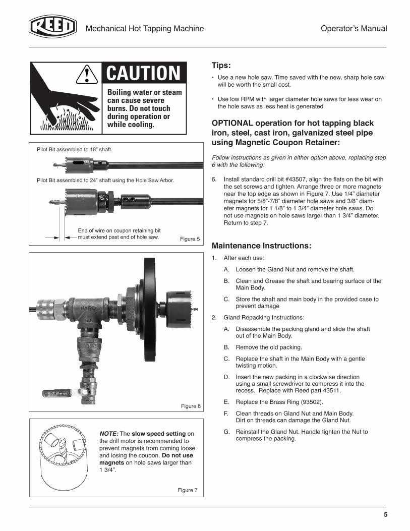
Pilot Bit assembled to 24” shaft using the Hole Saw Arbor.
Pilot Bit assembled to 18” shaft.
OPTIONAL operation for hot tapping black iron, steel, cast iron, galvanized steel pipe using Magnetic Coupon Retainer:
Follow instructions as given in either option above, replacing step 6 with the following:
6. Install standard drill bit #43507, align the flats on the bit with the set screws and tighten. Arrange three or more magnets near the top edge as shown in Figure 7. Use 1/4” diameter magnets for 5/8”-7/8” diameter hole saws and 3/8” diam- eter magnets for 1 1/8” to 1 3/4” diameter hole saws. Do not use magnets on hole saws larger than 1 3/4” diameter. Return to step 7.
Maintenance Instructions:1. After each use:
A. Loosen the Gland Nut and remove the shaft.
B. Clean and Grease the shaft and bearing surface of the Main Body.
C. Store the shaft and main body in the provided case to prevent damage
2. Gland Repacking Instructions:
A. Disassemble the packing gland and slide the shaft out of the Main Body.
B. Remove the old packing.
C. Replace the shaft in the Main Body with a gentle twisting motion.
D. Insert the new packing in a clockwise direction using a small screwdriver to compress it into the recess. Replace with Reed part 43511.
E. Replace the Brass Ring (93502).
F. Clean threads on Gland Nut and Main Body. Dirt on threads can damage the Gland Nut.
G. Reinstall the Gland Nut. Handle tighten the Nut to compress the packing.
NOTE: The slow speed setting on the drill motor is recommended to prevent magnets from coming loose and losing the coupon. Do not use magnets on hole saws larger than 1 3/4”.
Figure 7
End of wire on coupon retaining bit must extend past end of hole saw.
Tips:• Use a new hole saw. Time saved with the new, sharp hole saw will be worth the small cost.
• Use low RPM with larger diameter hole saws for less wear on the hole saws as less heat is generated
Boiling water or steamcan cause severeburns. Do not touch during operation orwhile cooling.
CAUTION
6
Mechanical Hot Tapping Machine Operator’s Manual
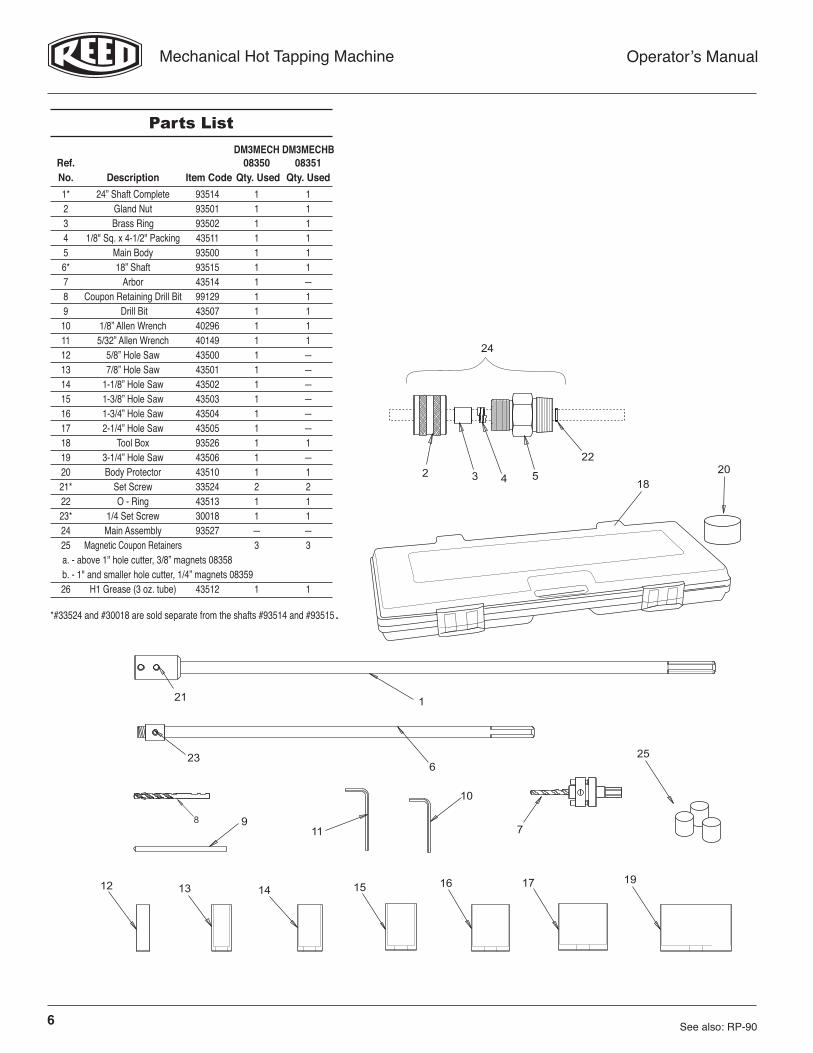
DM3MECH DM3MECHB Ref. 08350 08351 No. Description Item Code Qty. Used Qty. Used 1* 24” Shaft Complete 93514 1 1 2 Gland Nut 93501 1 1 3 Brass Ring 93502 1 1 4 1/8" Sq. x 4-1/2" Packing 43511 1 1 5 Main Body 93500 1 1 6* 18” Shaft 93515 1 1 7 Arbor 43514 1 — 8 Coupon Retaining Drill Bit 99129 1 1 9 Drill Bit 43507 1 1 10 1/8” Allen Wrench 40296 1 1 11 5/32” Allen Wrench 40149 1 1 12 5/8” Hole Saw 43500 1 — 13 7/8” Hole Saw 43501 1 — 14 1-1/8” Hole Saw 43502 1 — 15 1-3/8” Hole Saw 43503 1 — 16 1-3/4” Hole Saw 43504 1 — 17 2-1/4” Hole Saw 43505 1 — 18 Tool Box 93526 1 1 19 3-1/4” Hole Saw 43506 1 — 20 Body Protector 43510 1 1 21* Set Screw 33524 2 2 22 O - Ring 43513 1 1 23* 1/4 Set Screw 30018 1 1 24 Main Assembly 93527 — — 25 Magnetic Coupon Retainers 3 3 a. - above 1" hole cutter, 3/8” magnets 08358 b. - 1" and smaller hole cutter, 1/4” magnets 08359 26 H1 Grease (3 oz. tube) 43512 1 1
See also: RP-90
222 3 4 5 20
1
6
10
11
23
9
12 13 14 15 16 17
18
19
21
7
24
8
25
Parts List
*#33524 and #30018 are sold separate from the shafts #93514 and #93515.

7
Mechanical Hot Tapping Machine Operator’s Manual
Recommended Hole Sawing Speeds (RPM) for Bi-Metal Saws
Mild/ Size Size Galvanized Stainless Copper/ Inches mm Steel Steel Brass Aluminum PVC 5/8 16 530 275 730 825 7/8 22 390 195 520 585 1 1/8 29 300 150 400 450 1 3/8 35 250 125 330 375 1 3/4 44 195 95 260 295 2 1/4 57 150 75 200 230 3 1/4” 83 105 50 140 155
NO
T SP
ECIF
IED
8
Mechanical Hot Tapping Machine Operator’s Manual
REED Limited WarrantyREED will repair or replace tools with any defects due to faulty materials or workmanship for one (1) year or five (5) years from the date of purchase, as applicable. This warranty does not cover part failure due to tool abuse, misuse, or damage caused where repairs or modifications have been made or attempted by non REED authorized repair techni cians. This warranty ap-plies only to REED tools and does not apply to accessories. This warranty applies exclusively to the original purchaser.
One (1) year warranty: Power units for pneumatic, electric, hydraulic and battery-powered tools have a one year warranty. This includes, but is not limited to REED pumps, universal pipe cutter motors, power drives, power bevel tools, threading machines, cordless batteries and chargers.
Five (5) year warranty: Any REED tool not specified under the one (1) year warranty above is warrantied under the REED five (5) year warranty.
NO PARTY IS AUTHORIZED TO EXTEND ANY OTHER WARRANTY. NO WARRANTY FOR MERCHANTABILITY OR FITNESS FOR A PARTICULAR PURPOSE SHALL APPLY.
No warranty claims will be allowed unless the product in question is received freight prepaid at the REED factory. All warranty claims are limited to repair or replacement, at the option of REED, at no charge to the customer. REED is not liable for any damage of any sort, including incidental and consequential damages. This warranty gives you specific legal rights, and you may also have other rights which vary by state, province or country.
Warranty Effective December 1, 2018
1019-58350
Phone: 800-666-3691 or 814-452-3691 Fax: 800-456-1697 or 814-455-1697 www.reedmfgco.com
Reed Manufacturing Company1425 West 8th StreetErie, PA 16502 USA