
TAPPING ATTACHMENTS TAP CHUCKS MARKING … CNC-Attachments RCT . RDT Tapping Attachments Thread...
60
1 TAPPING ATTACHMENTS TAP CHUCKS MARKING HEADS ENGLISH VERSION
-
Upload
phungkhuong -
Category
Documents
-
view
283 -
download
9
Transcript of TAPPING ATTACHMENTS TAP CHUCKS MARKING … CNC-Attachments RCT . RDT Tapping Attachments Thread...

1
www.tapmatic.com
T A P P I N G A T T A C H M E N T ST A P C H U C K S
M A R K I N G H E A D S
E N G L I S H V E R S I O N

2
www.tapmatic.com
TAPMATIC Post Falls, USA
Quality, reliability and good service are what TAPMATIC stands for
Since its establishment in 1952, Tapmatic has manufactured tapping attachments of the highest quality and efficiency. Our focus on tapping attachments and tap holders, and our commitment to research and development, have led to the granting of more than 30 patents in countries all over the world. This investment in innovation and quality has made Tapmatic a world leading manufacturer of tap holding tools.
Today, Tapmatic products are represented through our agents in more than 40 countries.
Our Tapping Attachments and Tap Holders are produced using highly automated equipment. Tapmatic Corporation is an ISO 9001:2008 certified company. This guarantees you of our continued commitment to offering products of the highest quality.
Quality and economic efficiency, innovation and reliability are what have made Tapmatic one of the world’s most recognized names for Tapping.
Now Tapmatic also offers a complete program of marking tools. Whether your application calls for dot peen marking, scribing, or stamping, our tools allow you to mark the work piece during the machining process. Mark it while you make it.

3
Ind
exwww.tapmatic.comProduct Line Index
Description Model PageSelf-reversing CNC tapping attachmentsFor vertical and horizontal CNC machining centers, for continuous production. Extended spindles and interchangeable shanks available.
RCTRCT150
RDTSPD CNCASR, RSR
4-910
111213
Synchronized TappingFor rigid tapping on CNC machines with/without internal coolant, ER or QC-collets.
SFTSX
14-2223
Tension compression tap chucks For use on CNC machining centers, lathes and all machines with controlled feed when tapping cycle is not synchronized.
SMTATICNC
24-25262728
Self-reversing manual tapping attachments with pre-selective torque driveAutomatic reverse with increased reverse ratio. For manually operated drilling and milling machines.Heavy duty self-reversing tapping attachment also for machines with automatic feed
RXXTC/DC
SPD / SPD-QC
29-303132
33
In machine markingMarking tools for in machine marking.Dot peen marking tool.Scribing tool.Stamping head.
TapWriterScribe WriterMH
34-3536-3738-39
Quick-change adaptersModular accessories, compatible with the respective tapping attachment or chuck.
P - positive driveT - torque controlTF - rubber flex
40-4142-4344
Various accessoriesFor use on attachments and chucks.
Rubber flex colletsER-GBERClamping nutsSealing disks
4445-46474848
Various accessoriesFor use and installation of attachments and chucks on intended machines.
Torque wrenchesTorque BarsMounting deviceCNC ShanksArbors
49494950-51
InformationSpeed ChartInstallationER ClampingSafetyWarrantyApplication Questionnaire
52-545556575759
4
CN
C-A
ttac
hm
ents
www.tapmatic.comRCT . RDT Tapping Attachments
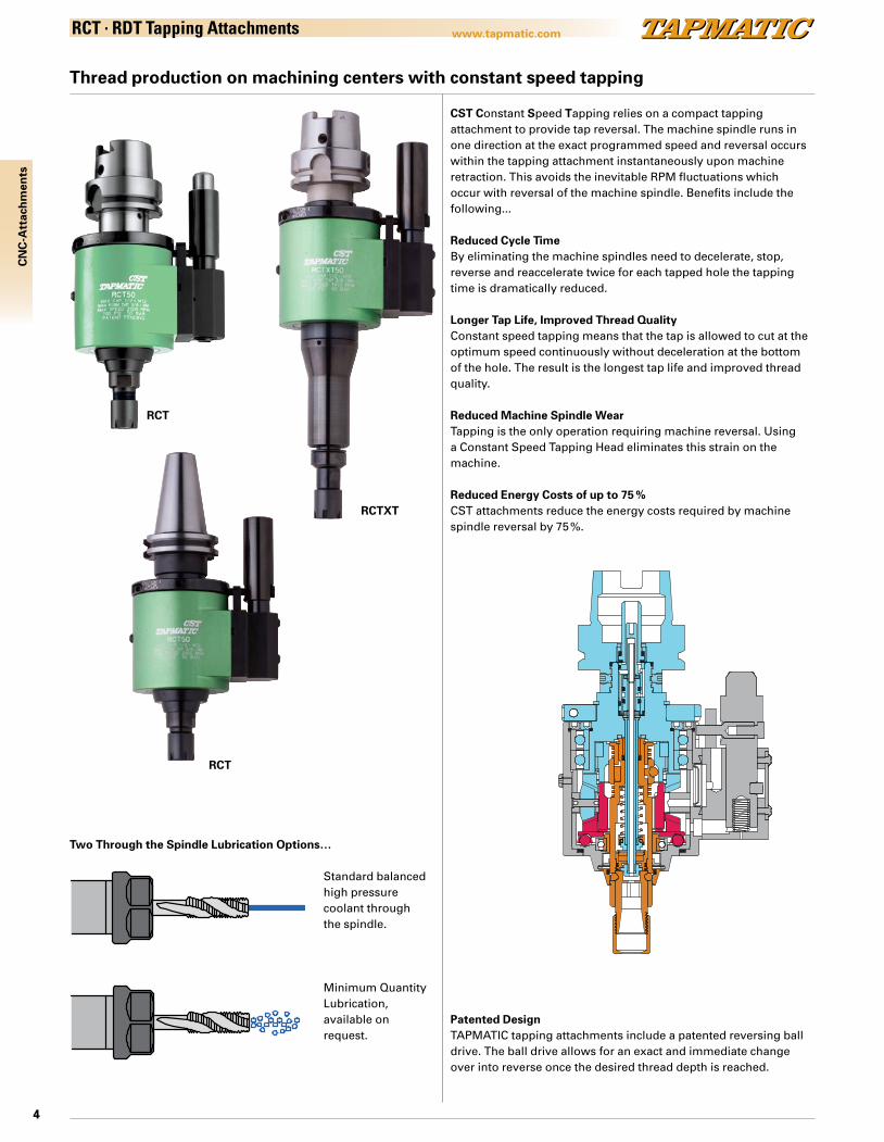
Thread production on machining centers with constant speed tapping
CST Constant Speed Tapping relies on a compact tapping attachment to provide tap reversal. The machine spindle runs in one direction at the exact programmed speed and reversal occurs within the tapping attachment instantaneously upon machine retraction. This avoids the inevitable RPM fluctuations which occur with reversal of the machine spindle. Benefits include the following...
Reduced Cycle TimeBy eliminating the machine spindles need to decelerate, stop, reverse and reaccelerate twice for each tapped hole the tapping time is dramatically reduced.
Longer Tap Life, Improved Thread QualityConstant speed tapping means that the tap is allowed to cut at the optimum speed continuously without deceleration at the bottom of the hole. The result is the longest tap life and improved thread quality.
Reduced Machine Spindle WearTapping is the only operation requiring machine reversal. Using a Constant Speed Tapping Head eliminates this strain on the machine.
Reduced Energy Costs of up to 75 % CST attachments reduce the energy costs required by machine spindle reversal by 75 %.
Patented DesignTAPMATIC tapping attachments include a patented reversing ball drive. The ball drive allows for an exact and immediate change over into reverse once the desired thread depth is reached.
Two Through the Spindle Lubrication Options…
Standard balanced high pressure coolant through the spindle.
Minimum Quantity Lubrication, available on request.
RCT
RCTXT
RCT
SECTION A-A
Draw No: 0550H6316 FOR CAT SEC Date: 10/1/13 Rev:
5
CN
C-A
ttac
hm
ents
www.tapmatic.comRCT . RDT Tapping Attachments
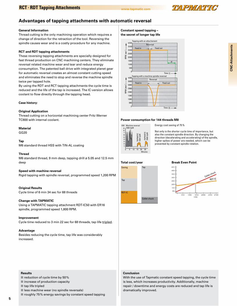
Advantages of tapping attachments with automatic reversal
General InformationThread cutting is the only machining operation which requires a change of direction for the retraction of the tool. Reversing the spindle causes wear and is a costly procedure for any machine.
RCT and RDT tapping attachmentsThese reversing tapping attachments are specially designed for fast thread production on CNC machining centers. They eliminate reversal related machine wear and tear and reduce energy consumption. The patented ball drive with integrated planet gear for automatic reversal creates an almost constant cutting speed and eliminates the need to stop and reverse the machine spindle twice per tapped hole.By using the RDT and RCT tapping attachments the cycle time is reduced and the life of the tap is increased. The IC-version allows coolant to flow directly through the tapping head.
Case history:
Original ApplicationThread cutting on a horizontal machining center Fritz Werner TC800 with internal coolant.
MaterialGG20
TapM6 standard thread HSS with TIN-AL coating
ThreadM6 standard thread, 9 mm deep, tapping drill ø 5.05 and 12.5 mm deep
Speed with machine reversalRigid tapping with spindle reversal, programmed speed 1,200 RPM
Original ResultsCycle time of 6 min 34 sec for 68 threads
Change with TAPMATICUsing a TAPMATIC tapping attachment RDT-IC50 with ER16spindle, programmed speed 1,800 RPM.
ImprovementCycle time reduced to 3 min 22 sec for 68 threads, tap life tripled.
AdvantageBesides reducing the cycle time, tap life was considerably increased.
Constant speed tapping – the secret of longer tap life
Power consumption for 144 threads M8
Energy cost saving of 75 %
Not only is the shorter cycle time of importance, but also the constant spindle direction. By changing the direction (decelerating and accelerating) of the spindle, higher spikes of power are needed, which can be prevented by constant spindle rotation.
Resultsn reduction of cycle time by 50 %n increase of production capacityn tap life tripledn less machine wear (no spindle reversals)n roughly 75 % energy savings by constant speed tapping
ConclusionWith the use of Tapmatic constant speed tapping, the cycle time is less, which increases productivity. Additionally, machine repair / downtime and energy costs are reduced and tap life is dramatically improved.
Tapping with an attachement
Reversal
Feed in Feed out
Tapping with a machine spindle reversal
Reversal
Feed in Feed out
Time
Time
RPM
RPM
Total cost/year Break Even Point
Collet chuck
Tap
Tap
RDT-IC
Saving
Collet chuck
RDT-IC
Minutes
Machine reversal1500 UpM
KW
TAPM
ATIC
1500
UpM
TAPM
ATIC
2500
UpM

6
CN
C-A
ttac
hm
ents
www.tapmatic.comRCT
High speed tapping attachments with integral HSK shank and internal coolant system
Features and Advantagesn high speed self-reversing tapping for
fastest cycle timen rugged design for years of production,
with little maintenancen high pressure internal coolant system, 50 Barn simple installation and programming
How to OrderPlease select the Tapping attachment (A) and stop arm (B) to fit your machine. Acces-sories like steel collets, sealing gaskets and stop blocks are not included. Please order these separately.
Tapmatic can provide a complete tool ready to fit your machine. Please simply provide the information shown on installation page 55, fill in the form on the back cover or contact us directly.
(A) Tapping Attachment RCT HSK
Notes: These internal coolant tools come standard with sealing nuts.These models are also available without internal coolant upon request.When using Roll Form Taps the tool’s capacity must be reduced 25 %.All dimensions are shown in mm. 25.4mm = 1"
Center Distance(42+L3)
Order codeRCT50
Order codeRCT85, 100
L3
55 0550551 3985551 1365 0550651 3985651 2380 0550801 3985801 38
(B) Stop Arm Assembly
Steel Collets Sealing Gaskets
Page 45-47 Page 48
Stop BlockPage 55
Speed Chart
Pages 52–54
Installation
Pages 55
Model Order code Capacity (steel)
Shank Collets Max. RPM Weight kg D d L1 L2
RCT50 0550H63161 M4.5–M12#10–1/2” ” ” ” ” ”
HSK63A ER16 2500 3.5 80 22 194 136
0550H80161 HSK80A 3.9 199 1410550H100161 HSK100A 4.8 201 1430550H63201 HSK63A ER20 2300 3.5 80 28 206 1360550H80201 HSK80A 3.9 211 1410550H100201 HSK100A 4.8 213 143
RCT85HS 0585H6325 M10–M20#7/16“–3/4” ” ”
HSK63A ER25 1500 4.2 80* 42 217 168
0585H8025 HSK80A 4.6 222 1730585H10025 HSK100A 5.5 224 175
RCT85HD 0585H6332 M12–M25#1/2“–1” ” ”
HSK63A ER32 1200 4.4 80* 50 223 168
0585H8032 HSK80A 4.8 228 1730585H10032 HSK100A 5.7 230 175
RCT100 05100H6340 M18–M27#3/4“–1” ” ”
HSK63A ER40 800 4.6 80* 63 229 168
05100H8040 HSK80A 5.0 234 17305100H10040 HSK100A 5.9 236 175
*Please note that size 85 and 100 tools have an 80mm square housing with ø102mm across corners
L2
L1
d
CENTERDISTANCE
16
L3
STOPBLOCK
SHANK
D 42
COOLANT
Draw No:RCT50 HSK FOR CATALOF Date: 9-6-13 Rev:
(A) (B)

7
www.tapmatic.com
45
33
40
L2
L1
d
30°
CENTERDISTANCE
L316
SHANK
STOPBLOCK
42D
COOLANT
(A) (B)
Draw No: RCTXT50 HSK FOR CATALOG Date: 8-7-13 Rev:
CN
C-A
ttac
hm
ents
RCTXT50
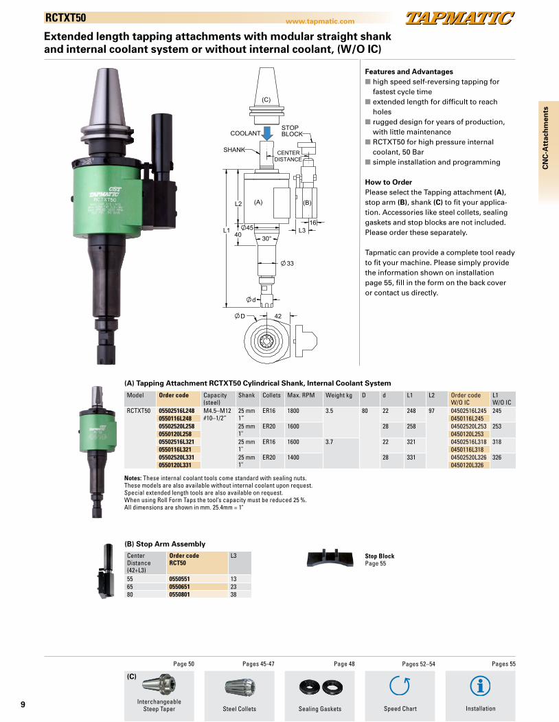
Extended length tapping attachments with integral HSK shank and internal coolant system
Features and Advantagesn high speed self-reversing tapping for
fastest cycle timen extended length for difficult to reach
holesn rugged design for years of production,
with little maintenancen RCTXT50 for high pressure internal
coolant, 50 Barn simple installation and programming
How to OrderPlease select the Tapping attachment (A), and stop arm (B) to fit your application. Accessories like steel collets, sealing gaskets and stop blocks are not included. Please order these separately.
Tapmatic can provide a complete tool ready to fit your machine. Please simply provide the information shown on installation page 55, fill in the form on the back cover or contact us directly.
Model Order code Capacity (steel)
Shank Collets Max. RPM Weight kg D d L1 L2
RCTXT50 0550H6316L287 M4.5–M12#10–1/2"
HSK63A ER16 1800 4.0 80 22 287 1360550H8016L292 HSK80A 4.4 292 1410550H10016L294 HSK100A 5.3 294 1430550H6320L297 HSK63A ER20 1600 4.0 80 28 297 1360550H8020L302 HSK80A 4.4 302 1410550H10020L304 HSK100A 5.3 304 1430550H6316L360 HSK63A ER16 1600 4.2 80 22 360 1360550H8016L365 HSK80A 4.6 365 1410550H10016L367 HSK100A 5.5 367 1430550H6320L370 HSK63A ER20 1400 4.2 80 28 370 1360550H8020L375 HSK80A 4.6 375 1410550H10020L377 HSK100A 5.5 377 143
Center Distance(42+L3)
Order codeRCT50
L3
55 0550551 1365 0550651 2380 0550801 38
(A) Tapping Attachment RCTXT50 HSK Shank, Internal Coolant System
Notes: Special extended length tools are also available on request.These models are also available without internal coolant on request.When using Roll Form Taps the tool’s capacity must be reduced 25 %.All dimensions are shown in mm. 25.4mm = 1"
(B) Stop Arm Assembly
Steel Collets Sealing Gaskets
Pages 45-47 Page 48
Stop BlockPage 55
Speed Chart
Pages 52–54
Installation
Pages 55
8
www.tapmatic.com
L1
L2
d
CENTERDISTANCE
L3
16
SHANK
STOPBLOCK
42 D
(A) (B)
(C)
Draw No:RCT50 25MM FOR CATALOG Date: 8-9-13 Rev:
COOLANT
RCT
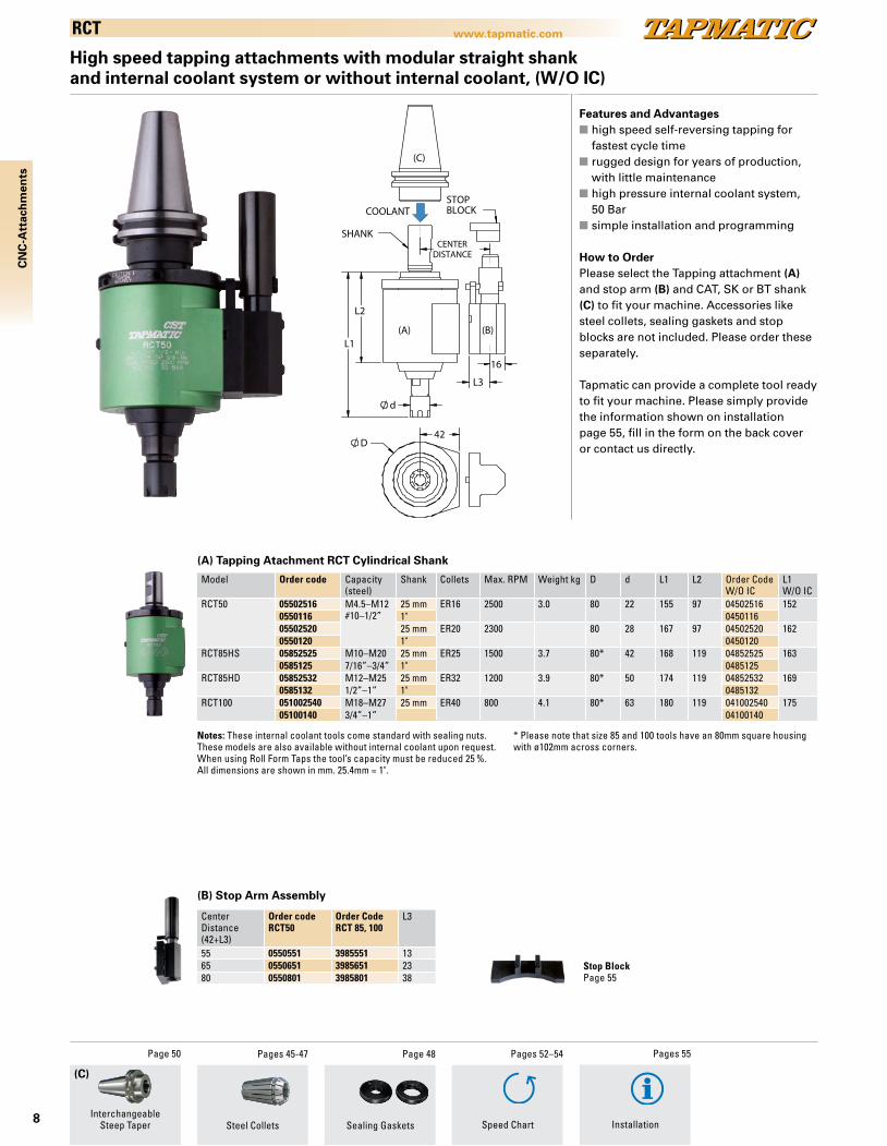
High speed tapping attachments with modular straight shank and internal coolant system or without internal coolant, (W/O IC)
Features and Advantagesn high speed self-reversing tapping for
fastest cycle timen rugged design for years of production,
with little maintenancen high pressure internal coolant system, 50 Barn simple installation and programming
How to OrderPlease select the Tapping attachment (A) and stop arm (B) and CAT, SK or BT shank (C) to fit your machine. Accessories like steel collets, sealing gaskets and stop blocks are not included. Please order these separately.
Tapmatic can provide a complete tool ready to fit your machine. Please simply provide the information shown on installation page 55, fill in the form on the back cover or contact us directly.
Model Order code Capacity (steel)
Shank Collets Max. RPM Weight kg D d L1 L2 Order CodeW/O IC
L1W/O IC
RCT50 05502516 M4.5–M12#10–1/2”
25 mm ER16 2500 3.0 80 22 155 97 04502516 1520550116 1" 045011605502520 25 mm ER20 2300 80 28 167 97 04502520 1620550120 1" 0450120
RCT85HS 05852525 M10–M20 25 mm ER25 1500 3.7 80* 42 168 119 04852525 1630585125 7/16”–3/4” 1" 0485125
RCT85HD 05852532 M12–M25 25 mm ER32 1200 3.9 80* 50 174 119 04852532 1690585132 1/2”–1” 1" 0485132
RCT100 051002540 M18–M27 25 mm ER40 800 4.1 80* 63 180 119 041002540 17505100140 3/4”–1” 04100140
Center Distance(42+L3)
Order codeRCT50
Order CodeRCT 85, 100
L3
55 0550551 3985551 1365 0550651 3985651 2380 0550801 3985801 38
(A) Tapping Atachment RCT Cylindrical Shank
(B) Stop Arm Assembly
Notes: These internal coolant tools come standard with sealing nuts.These models are also available without internal coolant upon request.When using Roll Form Taps the tool’s capacity must be reduced 25 %.All dimensions are shown in mm. 25.4mm = 1".
Steel Collets Sealing Gaskets
Pages 45-47 Page 48
Stop BlockPage 55
Speed Chart
Pages 52–54
Installation
Pages 55
CN
C-A
ttac
hm
ents
(C)
InterchangeableSteep Taper
Page 50
* Please note that size 85 and 100 tools have an 80mm square housing with ø102mm across corners.
9
www.tapmatic.com
L1
L2
45 40 30°
33
d
CENTERDISTANCE
16 L3
STOPBLOCK
SHANK
D 42
COOLANT
(A) (B)
(C)
Draw No:RCTXT50 25MM FOR CATALOG Date: 08-28-13 Rev:
CN
C-A
ttac
hm
ents
(C)
RCTXT50
Extended length tapping attachments with modular straight shank and internal coolant system or without internal coolant, (W/O IC)
Features and Advantagesn high speed self-reversing tapping for
fastest cycle timen extended length for difficult to reach
holesn rugged design for years of production,
with little maintenancen RCTXT50 for high pressure internal
coolant, 50 Barn simple installation and programming
How to OrderPlease select the Tapping attachment (A), stop arm (B), shank (C) to fit your applica-tion. Accessories like steel collets, sealing gaskets and stop blocks are not included. Please order these separately.
Tapmatic can provide a complete tool ready to fit your machine. Please simply provide the information shown on installation page 55, fill in the form on the back cover or contact us directly.
Model Order code Capacity (steel)
Shank Collets Max. RPM Weight kg D d L1 L2 Order codeW/O IC
L1W/O IC
RCTXT50 05502516L248 M4.5–M12#10–1/2”
25 mm1”
ER16 1800 3.5 80 22 248 97 04502516L245 2450550116L248 0450116L24505502520L258 25 mm
1"ER20 1600 28 258 04502520L253 253
0550120L258 0450120L25305502516L321 25 mm
1"ER16 1600 3.7 22 321 04502516L318 318
0550116L321 0450116L31805502520L331 25 mm
1"ER20 1400 28 331 04502520L326 326
0550120L331 0450120L326
Center Distance(42+L3)
Order codeRCT50
L3
55 0550551 1365 0550651 2380 0550801 38
(A) Tapping Attachment RCTXT50 Cylindrical Shank, Internal Coolant System
(B) Stop Arm Assembly
Notes: These internal coolant tools come standard with sealing nuts.These models are also available without internal coolant upon request.Special extended length tools are also available on request. When using Roll Form Taps the tool’s capacity must be reduced 25 %.All dimensions are shown in mm. 25.4mm = 1"
Steel Collets Sealing GasketsInterchangeable
Steep Taper
Page 50 Pages 45-47 Page 48
Stop BlockPage 55
Speed Chart
Pages 52–54
Installation
Pages 55

10
CN
C-A
ttac
hm
ents
(C)
www.tapmatic.comRCT150
Large capacity tapping attachments with modular straight shank and internal coolant system
The RCT150 is our new, large capacity self-reversing tapping attachment for CNC machi-ning centers. Heavy duty precision gearing transmits high torque for reversing tap sizes up to M42. They are ruggedly built to provide years of service, and include high volume, high pressure internal coolant.
The RCT150 was developed for the large tapping applications required by the wind energy, heavy industry, and power generation fields. By eliminating machine spindle reversal, cycle time is dramatically improved, electrical power consumption is reduced by as much as 75 % and wear and tear to the machine spindle caused by stopping and reversing twice for each tapped hole is eliminated.
Features and Advantagesn high speed self-reversing tapping for
fastest cycle timen rugged design for years of production,
with little maintenancen high pressure internal coolant system, 50 Barn simple installation and programming
How to OrderPlease select the Tapping attachment (A), stop arm (B) and CAT, SK, or BT shank (C), to fit your machine. Accessories like steel collets, sealing gaskets and stop blocks are not included. Please order these separately.
Tapmatic can provide a complete tool ready to fit your machine. Please simply provide the information shown on installation page 55, fill in the form on the back cover or contact us directly.
(A) Tapping Attachment RCT150 Cylindrical Shank
Model Order code Capacity (steel)
Shank Collets Max. RPM Weight kg d L1 L2
RCT150 051504050 M25–M42 40 mm ER50 500 6.2 78 234 1581”–1 5/8”
Center Distance(67+L3)
Order codeRCT150
L3
80 0515080 13110 05150110 43
Notes: When using Roll Form Taps the tool’s capacity must be reduced 25%.All dimensions are shown in mm. 25.4mm = 1"
(B) Stop Arm Assembly
L2
L1
d
DISTANCECENTER
STOPBLOCKSHANK
118.50
67L3
19
(A) (B)
(C)
COOLANT
Steel ColletsInterchangeable
Steep Taper
Page 50 Pages 45-47 Page 48
Sealing Gaskets
Stop BlockPage 55
Speed Chart
Pages 52–54
Installation
Pages 55

11
www.tapmatic.com
CN
C-A
ttac
hm
ents
(C)
RDT
Features and Advantagesn high speed self-reversing tapping for
fastest cycle timen rugged design for years of production,
with little maintenancen simple installation and programmingn large capacity
How to OrderPlease select the Tapping attachment (A), stop arm (B) and CAT, SK, or BT shank (C), to fit your machine. Accessories like steel collets, sealing gaskets and stop blocks are not included. Please order these separately.
Tapmatic can provide a complete tool ready to fit your machine. Please simply provide the information shown on installation page 55, fill in the form on the back cover or contact us directly.
High speed tapping attachments with modular straight shank, without internal coolant system
Model Order code Capacity (steel)
Shank Collets Max. RPM Weight kg D d L1 L2
RDT15 3915258HD M1–M3 25 mm ER8 5000 1.7 57 12 97 79391518HD #0–#6 1”
RDT25 39252511 M2–M6 25 mm ER11 4000 1.7 57 19 106 793925111 #4–1/4” 1”
RDT50 39502516 M4.5–M12 25 mm ER16 2000 3.7 80 28 126 933950116 10”–1/2” 1”
Center Distance(42+L3)
Order codeRDT15RDT25
Order codeRDT50
L3
55 3925551 3950551 1365 3925651 3950651 2380 3925801 3950801 38
(A) Tapping Attachment RDT Cylindrical Shank
Notes: When using Roll Form Taps the tool’s capacity must be reduced 25 %.To hold larger taps with RDT50 ER16, use standard collet 20953 and separate square drives packaged with tool.All dimensions are shown in mm. 25.4mm = 1"
(B) Stop Arm Assembly
Steel ColletsInterchangeable
Steep Taper
Page 50 Pages 45-47
L1L2
d
DISTANCECENTERSHANK
STOPBLOCK
(C)
D42 L3
16
(A)
(B)
Stop BlockPage 55
Speed Chart
Pages 52–54
Installation
Pages 55

12
www.tapmatic.com
(C)
CN
C-A
ttac
hm
ents
SPD CNC
Economical tapping attachments with modular straight shank
The SPD CNC are low cost, self-reversing tapping attachments for CNC machining centers. They use ER collets and employ a simple stop arm system for easy installation on machines with automatic tool change.
The SPD CNC were developed specifically for short run job shop applications. Their low cost make them economical to use, and they provide all the advantages associated with the elimination of machine spindle reversal. Faster cycle time, elimination of machine spindle wear and tear due to reversal, lower energy costs and longer tap life.
Features and Advantagesn faster cycle timen eliminates machine reversal for lower
energy costs and reduced wear to machine spindle
n ER colletsn simple installation with torque bar and
stop armn Stop Arm Assembly includedn simple programming
How to OrderPlease select the Tapping attachment (A) and CAT, SK or BT shank (C) to fit your machine. Please order accessories like collets, and torque bars separately. Please note the tool comes with a stop arm that can be modified or you can also order a readymade stop arm to fit your machine’s bolt circle. Torque bar holders are not included and need to be ordered according to the bolt size of your machine.
(A) Tapping Attachment SPD CNC Cylindrical Shank
L2
L1
d
TORQUEBAR
CENTERDISTANCE
STOPARM
SHANK
D71
(C)
(A)
Model Order code Shank Capacity (steel)
Collets Max. RPM Weight kg d L1 L2
SPD CNC3 0283251152 25 mm M2–M6 ER11 2000 1.7 19 106 73028311152 1” #4–1/4”
SPD CNC5 0285251652 25 mm M4.5–M12 ER16 1500 3.7 28 140 91028511652 1” #10–1/2”
Notes: The SPD CNC tools include a stop arm assembly, but it is possible to use the RDT25 and 50 stop arm assemblies with them as well. When using Roll Form Taps the tool’s capacity must be reduced 25 %.All dimensions are shown in mm. 25.4mm = 1"
Steel ColletsInterchangeable
Steep Taper
Page 50 Pages 45-47
Stop Arm Plate
Order code Center distancemm
723420 53-69723421 68-77723422 74-88723423 86-100
Torque Bar Holder AssembliesPage 55
Pages 52–54 Pages 55
Speed Chart Installation
13
www.tapmatic.com
CN
C-A
ttac
hm
ents
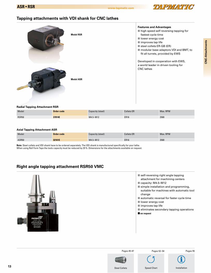
ASR • RSR
Tapping attachments with VDI shank for CNC lathes
Model RSR
Model ASR
Features and Advantagesn high speed self reversing tapping for fastest cycle timen lower energy costn improves tap lifen steel collets ER-GB (ER)n modular base adaptors VDI and BMT, to
fit all turrets, provided by EWS
Developed in cooperation with EWS, a world leader in driven tooling for CNC lathes
Model Order code Capacity (steel) Collets ER Max. RPM
RSR50 37014E M4.5–M12 ER16 2500
Axial Tapping Attachment ASR
Model Order code Capacity (steel) Collets ER Max. RPM
ASR50 32161E M4.5–M12 ER16 2500
Note: Steel collets and VDI shank have to be ordered separately. The VDI shank is manufactured specifically for your lathe.When using Roll Form Taps the tools capacity must be reduced by 25 %. Dimensions for the attachments available on request.
Steel Collets
Pages 45-47
Radial Tapping Attachment RSR
Speed Chart
Pages 52–54
Installation
Pages 55
Right angle tapping attachment RSR50 VMC
n self-reversing right angle tapping attachment for machining centers
n capacity: M4.5–M12n simple installation and programming,
suitable for machines with automatic tool change
n automatic reversal for faster cycle timen lower energy costn improves tap lifen eliminates secondary tapping operationsn on request
Radial Tapping Attachment RSR
14
www.tapmatic.com
J J
SECTION J-J
Draw No: Date: Rev:
Syn
chro
niz
ed T
app
ing
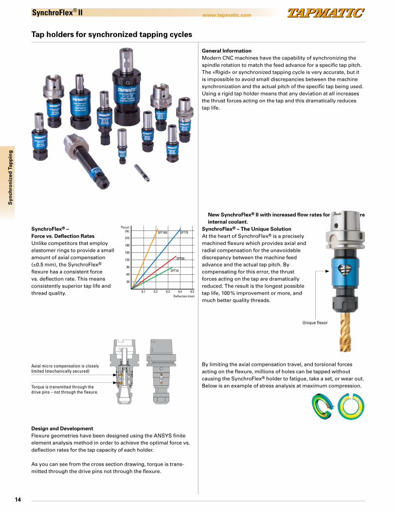
SynchroFlex® II
Tap holders for synchronized tapping cycles
General InformationModern CNC machines have the capability of synchronizing the spindle rotation to match the feed advance for a specific tap pitch. The «Rigid» or synchronized tapping cycle is very accurate, but it is impossible to avoid small discrepancies between the machine synchronization and the actual pitch of the specific tap being used. Using a rigid tap holder means that any deviation at all increases the thrust forces acting on the tap and this dramatically reduces tap life.
210
180
0,1 0,2 0,3 0,4
SFT10
SFT50
SFT75SFT100
0,5
150
120
90
60
30
Thrust(N)
Deflection (mm)
SynchroFlex® – The Unique SolutionAt the heart of SynchroFlex® is a precisely machined flexure which provides axial and radial compensation for the unavoidable discrepancy between the machine feed advance and the actual tap pitch. By compensating for this error, the thrust forces acting on the tap are dramatically reduced. The result is the longest possible tap life, 100 % improvement or more, and much better quality threads.
SynchroFlex® – Force vs. Deflection RatesUnlike competitors that employ elastomer rings to provide a small amount of axial compensation (±0.5 mm), the SynchroFlex® flexure has a consistent force vs. deflection rate. This means consistently superior tap life and thread quality.
By limiting the axial compensation travel, and torsional forces acting on the flexure, millions of holes can be tapped without causing the SynchroFlex® holder to fatigue, take a set, or wear out. Below is an example of stress analysis at maximum compression.
Design and DevelopmentFlexure geometries have been designed using the ANSYS finite element analysis method in order to achieve the optimal force vs. deflection rates for the tap capacity of each holder.
As you can see from the cross section drawing, torque is trans-mitted through the drive pins not through the flexure.
Axial micro compensation is closely limited (mechanically secured)
Torque is transmitted through the drive pins – not through the flexure.
New SynchroFlex® II with increased flow rates for high pressure internal coolant.
Unique flexor
15
www.tapmatic.com
Syn
chro
niz
ed T
app
ing
SynchroFlex® II
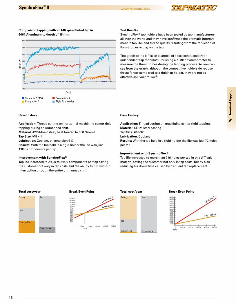
Tapmatic SFT50Competitor 1
Competitor 2Rigid Tap Holder
Depth
Thru
st (N
)
Test ResultsSynchroFlex® tap holders have been tested by tap manufacturers all over the world and they have confirmed the dramatic improve-ment in tap life, and thread quality resulting from the reduction of thrust forces acting on the tap.
The graph to the left is an example of a test conducted by an independent tap manufacturer using a Kistler dynamometer to measure the thrust forces during the tapping process. As you can see from the graph, although the competitive holders do reduce thrust forces compared to a rigid tap holder, they are not as effective as SynchroFlex®.
Comparison tapping with an M6 spiral fluted tap in 6061 Aluminum to depth of 18 mm.
Case History
Application: Thread cutting on horizontal machining center rigid tapping during an unmanned shift.Material: 42CrMo4V steel, heat treated to 650 N/mm2
Tap Size: M8 x 1Lubrication: Coolant, oil emulsion 6 %Results: With the tap held in a rigid holder the life was just 1‘000 components per tap.
Improvement with SynchroFlex®
Tap life increased to 2‘400 to 2‘900 components per tap saving the customer not only in tap costs, but the ability to run without interruption through the entire unmanned shift.
Case History
Application: Thread cutting on machining center rigid tapping.Material: CF8M steel castingTap Size: #10-32Lubrication: CoolantResults: With the tap held in a rigid holder the life was just 72 holes per tap.
Improvement with SynchroFlex®
Tap life increased to more than 216 holes per tap in this difficult material saving the customer not only in tap costs, but by also reducing his down time caused by frequent tap replacement.
Total cost/year
Collet chuck
Tap
Tap
SynchroFlex
Saving
Total cost/year Break Even Point
Collet chuck
Tap
Tap
SynchroFlex
Saving
Collet chuck
Break Even Point
Collet chuck
SynchroFlex
SynchroFlex

16
www.tapmatic.comS
ynch
ron
ized
Tap
pin
gSynchroFlex® II
Overview of the SynchroFlex® program
Six Sizes to Cover a Wide Range of Tapsn SFT II 5 with capacity M1 – M3n SFT II 10 with capacity M2 – M5n SFT II 50 with capacity M4 – M12n SFT II 75 with capacity M8 – M20n SFT II 100 with capacity M16 – M30n SFT II 150 with capacity M22 – M48
Pictured with ER-collet, spindle and straight shank
Available with QC spindleAccepts the standard Quick Change adapters or Tapmatic’s ER collet chuck QC adapters for improved tap grip.
Integral shank modelsTapmatic offers standard integral shank HSK and Tapmatic Capto tools. ABS shanks are also available on request.
We can also offer integral Steep Taper shank tools but in most cases we recommend a modular system using a cylindrical shank SynchroFlex® together with our Short Projection SK, BT or CAT shank.
No hole beyond your reachFour standard extensions are available which increase the tool length by 50, 100, 150, or 200 mm.Special extensions are also available to fit your specific application. Our extensions keep the flexure in close proximity to the tap ensuring the best performance.
Internal Coolant and MQLTapmatic’s high pressure internal coolant system may be used at pressures up to 80 bar without affecting the axial compensation.
Tapmatic also can provide tools ready for Minimum Quantity Lubrication through the spindle. Our system provides direct flow of air and lubricant to the back of the tap. See page 22.
SFT IIHigh Pressure Internal Coolantwith increased flow rates
Minimum Quantity LubricationAvailable for 1 channel orMulti channel systems
A A
SECTION A-A
Draw No: 4175h6325 for catalog ik Date: 9-6-13 Rev:
A A
SECTION A-A
ADJUSTINGSCREW
Draw No: 4175h6325m for catalog Date: 9-6-13 Rev:
SFT II 150
SFT II 100
SFT II 75
SFT II 50
SFT II 10 SFT II 5

17
www.tapmatic.com
L1d1
D1
D
d
L
SHANK
COOLANT
(A)
(C)
Draw No: 417525QC for catalog Date: 9-5-13 Rev:
D
D1
d
L
SHANK
COOLANT
(A)
(B)
Draw No: 41752525 for catalog Date: 9-5-13 Rev:
Syn
chro
niz
ed T
app
ing
SynchroFlex® II
Model Order code(with seal nut)
Capacity (steel)
Shank Collets Weight kg D D1 d L(with seal nut)
Order code(nut w/o seal)
L(nut w/o seal)
SFT II 5 M1–M3#00–#5
12 mm ER8 0.1 12.0 12.0 12 41051208 28
SFT II 10 M2–M5 25 mm ER11 0.4 23.5 23.5 19 41102511 52#2–#10 1” 4110111
20 mm 4110201116 mm 41101611
SFT II 50 41502520 M4.5–M12 25 mm ER20 0.5 34.6 36.3 34 69 41502520N 644150120 #8–1/2” 1” 4150120N41502020 20 mm 41502020N
SFT II 75 41752525 M8–M20 25 mm ER25 1.0 44.0 45.6 42 88 41752525N 834175125 1/4”–3/4” 1” 4175125N
SFT II 100 411002540 M16–M30 25 mm ER40 2.0 62.0 63.6 63 117 411002540N 11241100140 5/8”–1” 1” 41100140N
SFT II 150 411504050 *
M22–M487/8”–1 7/8”
40 mm ER50 5.1 80.0 86.0 78 166 411504050N 159
Model Order code Capacity (steel)
Shank Adapter Weight kg D D1 d L
SFT II 50 415025QC M4–M12 25 mm Nr. 1 0.5 34.6 36.3 35 5641501QC #8”–#1/2” 1”
SFT II 75 417525QC M8–M16 25 mm Nr. 1 1.0 44.0 45.6 40 7241751QC #1/4”–5/8” 1”
SFT II 100 4110025QC M16–M30 25 mm Nr. 2 2.0 62.0 63.6 59 105411001QC 1/2”–7/8” 1”
(B)
Sealing GasketsInterchangeable
Steep Taper
Page 50 Page 48Pages 45-47
Steel Collets
ER Collet Chuck Quick-Change
Synchronous feed tap holders with modular straight shank, with internal coolant system
Features and Advantagesn increase tap life by 100 % or moren improves thread qualityn reduces downtime by lowering frequency of tap replacementn Axial compensation +/- 0.5mm (SFT II 150 +/- 1.5mm)n wide range of sizesn available with ER collet or Quick Change chuckn available with high pressure internal coolant system up to 80 bar
(Balanced Coolant System)
How to OrderPlease select the tap holder (A) and SK or BT shank (B), to fit your machine. For Quick Change models order ER collet adapter (C) shown below or standard adapters shown in accessories section. Please order accessories like collets and sealing gaskets separately as they are not included.
(A) Tap Holder SFTII Cylindrical Shank, ER Collet Chuck, Internal Coolant System
*Note: Availability of inch size ER50GB collets is limited. Please consult a Tapmatic sales representative for sizes currently available.These internal coolant tools come standard with sealing nut, but tools with standard nuts are also available. When using Roll Form Taps the tool’s capacity must be reduced 25 %.All dimensions are shown in mm. 25.4mm + 1”.
(A) Tap Holder SFTII Cylindrical Shank, Quick-Change Internal Coolant System
(C) ER collet adapter
Speed Chart
Pages 52–54
Order codewith Standard Nut
Adapter Collets d1 L1 Order codewith Seal Nutfor BCS version
L1(BCS)
8208216 Nr. 1 ER16 22 24 8208216S 288218220 Nr. 1 ER20 28 35 8218220S 408288225 Nr. 2 ER25 35 38 8288225S 438288232 Nr. 2 ER32 50 48 8288232S 53
Note: When using Roll Form Taps the tool’s capacity must be reduced 25 %.All dimensions are shown in mm. 25.4mm = 1".For best performance we recommend ER collet adapters shown below.
18
www.tapmatic.com
COOLANT
LD1
D
L1d1
d
SHANK
(C)
(A)
Draw No: 4175H63QC FOR CATALOT Date: 9-6-13 Rev:
D1
D
d
L
SHANK
COOLANT
(A)
Draw No:4175H6325 FOR CATALOG Date: 9-5-13 Rev:
Syn
chro
niz
ed T
app
ing
SynchroFlex® II
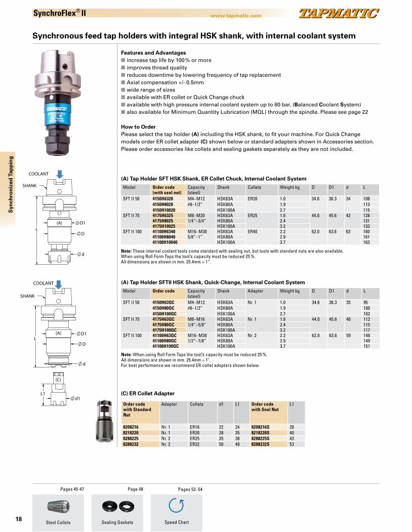
Synchronous feed tap holders with integral HSK shank, with internal coolant system
Features and Advantagesn increase tap life by 100 % or moren improves thread qualityn reduces downtime by lowering frequency of tap replacementn Axial compensation +/- 0.5mmn wide range of sizesn available with ER collet or Quick Change chuckn available with high pressure internal coolant system up to 80 bar. (Balanced Coolant System)n also available for Minimum Quantity Lubrication (MQL) through the spindle. Please see page 22
How to OrderPlease select the tap holder (A) including the HSK shank, to fit your machine. For Quick Change models order ER collet adapter (C) shown below or standard adapters shown in Accessories section. Please order accessories like collets and sealing gaskets separately as they are not included.
Sealing Gaskets
Page 48Pages 45-47
Steel Collets
(C) ER Collet Adapter
Model Order code(with seal nut)
Capacity (steel)
Shank Collets Weight kg D D1 d L
SFT II 50 4150H6320 M4–M12 HSK63A ER20 1.0 34.6 36.3 34 1084150H8020 #8–1/2” HSK80A 1.9 1134150H10020 HSK100A 2.7 115
SFT II 75 4175H6325 M8–M20 HSK63A ER25 1.6 44.0 45.6 42 1284175H8025 1/4”–3/4” HSK80A 2.4 1314175H10025 HSK100A 3.2 133
SFT II 100 41100H6340 M16–M30 HSK63A ER40 2.2 62.0 63.6 63 16041100H8040 5/8”–1” HSK80A 2.9 16141100H10040 HSK100A 3.7 163
(A) Tap Holder SFT HSK Shank, ER Collet Chuck, Internal Coolant System
Note: These internal coolant tools come standard with sealing nut, but tools with standard nuts are also available. When using Roll Form Taps the tool’s capacity must be reduced 25 %.All dimensions are shown in mm. 25.4mm + 1”.
Model Order code Capacity (steel)
Shank Adapter Weight kg D D1 d L
SFT II 50 4150H63QC M4–M12 HSK63A Nr. 1 1.0 34.6 36.3 35 954150H80QC #8–1/2” HSK80A 1.9 1004150H100QC HSK100A 2.7 102
SFT II 75 4175H63QC M8–M16 HSK63A Nr. 1 1.6 44.0 45.6 40 1124175H80QC 1/4”–5/8” HSK80A 2.4 1154175H100QC HSK100A 3.2 117
SFT II 100 41100H63QC M16–M30 HSK63A Nr. 2 2.2 62.0 63.6 59 14841100H80QC 1/2”–7/8” HSK80A 2.9 14941100H100QC HSK100A 3.7 151
(A) Tap Holder SFTII HSK Shank, Quick-Change, Internal Coolant System
Speed Chart
Pages 52–54
Order codewith Standard Nut
Adapter Collets d1 L1 Order codewith Seal Nut
L1
8208216 Nr. 1 ER16 22 24 8208216S 288218220 Nr. 1 ER20 28 35 8218220S 408288225 Nr. 2 ER25 35 38 8288225S 438288232 Nr. 2 ER32 50 48 8288232S 53
Note: When using Roll Form Taps the tool’s capacity must be reduced 25 %.All dimensions are shown in mm. 25.4mm = 1".For best performance we recommend ER collet adapters shown below.
19
www.tapmatic.com
LD1
D
d
d1L1
SHANK
COOLANT
(A)
(C)
Draw No: 4175C6QC FOR CATALOG Date: 9-6-13 Rev:
L
D1
D
d
SHANK
COOLANT
(A)
Draw No: 4175C625 FOR CATALOG Date: 9-6-13 Rev:
Syn
chro
niz
ed T
app
ing
SynchroFlex® II
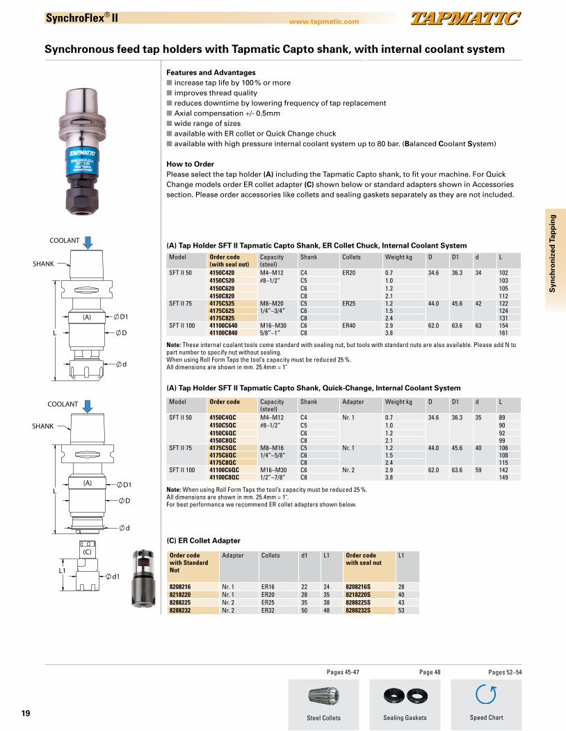
Synchronous feed tap holders with Tapmatic Capto shank, with internal coolant system
Sealing Gaskets
Page 48Pages 45-47
Steel Collets
Features and Advantagesn increase tap life by 100 % or moren improves thread qualityn reduces downtime by lowering frequency of tap replacementn Axial compensation +/- 0.5mmn wide range of sizesn available with ER collet or Quick Change chuckn available with high pressure internal coolant system up to 80 bar. (Balanced Coolant System)
How to OrderPlease select the tap holder (A) including the Tapmatic Capto shank, to fit your machine. For Quick Change models order ER collet adapter (C) shown below or standard adapters shown in Accessories section. Please order accessories like collets and sealing gaskets separately as they are not included.
Model Order code(with seal nut)
Capacity (steel)
Shank Collets Weight kg D D1 d L
SFT II 50 4150C420 M4–M12 C4 ER20 0.7 34.6 36.3 34 1024150C520 #8–1/2” C5 1.0 1034150C620 C6 1.2 1054150C820 C8 2.1 112
SFT II 75 4175C525 M8–M20 C5 ER25 1.2 44.0 45.6 42 1224175C625 1/4”–3/4” C6 1.5 1244175C825 C8 2.4 131
SFT II 100 41100C640 M16–M30 C6 ER40 2.9 62.0 63.6 63 15441100C840 5/8”–1” C8 3.8 161
(A) Tap Holder SFT II Tapmatic Capto Shank, ER Collet Chuck, Internal Coolant System
Note: These internal coolant tools come standard with sealing nut, but tools with standard nuts are also available. Please add N to part number to specify nut without sealing.When using Roll Form Taps the tool’s capacity must be reduced 25 %.All dimensions are shown in mm. 25.4mm = 1"
(C) ER Collet Adapter
Model Order code Capacity (steel)
Shank Adapter Weight kg D D1 d L
SFT II 50 4150C4QC M4–M12 C4 Nr. 1 0.7 34.6 36.3 35 894150C5QC #8–1/2” C5 1.0 904150C6QC C6 1.2 924150C8QC C8 2.1 99
SFT II 75 4175C5QC M8–M16 C5 Nr. 1 1.2 44.0 45.6 40 1064175C6QC 1/4”–5/8” C6 1.5 1084175C8QC C8 2.4 115
SFT II 100 41100C6QC M16–M30 C6 Nr. 2 2.9 62.0 63.6 59 14241100C8QC 1/2”–7/8” C8 3.8 149
(A) Tap Holder SFT II Tapmatic Capto Shank, Quick-Change, Internal Coolant System
Speed Chart
Pages 52–54
Order codewith Standard Nut
Adapter Collets d1 L1 Order codewith seal nut
L1
8208216 Nr. 1 ER16 22 24 8208216S 288218220 Nr. 1 ER20 28 35 8218220S 408288225 Nr. 2 ER25 35 38 8288225S 438288232 Nr. 2 ER32 50 48 8288232S 53
Note: When using Roll Form Taps the tool’s capacity must be reduced 25 %.All dimensions are shown in mm. 25.4mm = 1".For best performance we recommend ER collet adapters shown below.

20
www.tapmatic.comS
ynch
ron
ized
Tap
pin
gSynchroFlex®
Synchronous feed tap holders with VDI shank, with internal coolant system
Features and Advantagesn increase tap life by 100 % or moren improves thread qualityn reduces downtime by lowering frequency of tap replacementn Axial compensation +/- 0.5mmn wide range of sizesn available with high pressure internal coolant system up to 80 bar. (Balanced Coolant System)
How to OrderPlease select the tap holder (A) including the VDI shank, to fit your machine. Please order accessories like collets and sealing gaskets separately as they are not included.
Sealing Gaskets
Page 48Pages 45-47
Steel Collets
Model Order code(with seal nut)
Capacity (steel)
Shank Collets Weight kg D D1 d L
SFT II 50 4150VDI3020 M4–M12 VDI 30 ER20 1.2 34.6 36.3 34 97#8–1/2”
4150VDI4020 VDI 40 2.1 97SFT II 75 4175VDI3025 M8–M20 VDI 30 ER25 1.5 44 45.6 42 116
1/4”–3/4”4175VDI4025 VDI 40 2.4 116
(A) Tap Holder SFT II VDI Shank, ER Collet Chuck, Internal Coolant System
Note: These internal coolant tools come standard with sealing nut, but tools with standard nutsare als available. Please add N to part number to specify nut without sealing.When using Roll Form Taps the tool’s capacity must be reduced 25 %.All dimensions are shown in mm. 25.4mm = 1"
Speed Chart
Pages 52–54
16
D1
D
d
L
SHANK
COOLANT
04175VDI3025CTLG
MJ 7/21/16PROPRIETARY AND CONFIDENTIAL
THE INFORMATION CONTAINED IN THIS DRAWING IS THE SOLE PROPERTY OF TAPMATIC CORPORATION. ANY REPRODUCTION IN PART OR AS A WHOLE WITHOUT THE WRITTEN PERMISSION OF TAPMATIC CORPORATION IS PROHIBITED.
COMMENTS:
DRAWN:
DATENAME
DO NOT SCALE DRAWINGREV.
ADWG. NO.SIZE
TAPMATIC CORPORATIONPOST FALLS, IDAHO
DESCRIPTION
SFT75 II VDI 30 CLTG
SCALE -1:1
21
www.tapmatic.com
50128
Draw No: 4175h63l17825 for catalog Date: 9-6-13 Rev:
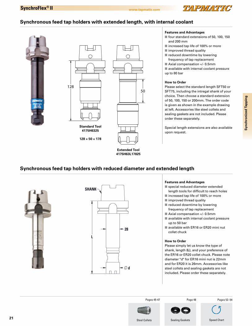
SynchroFlex® II
Synchronous feed tap holders with extended length, with internal coolant
Synchronous feed tap holders with reduced diameter and extended length
Features and Advantagesn four standard extensions of 50, 100, 150 and 200 mmn increased tap life of 100% or moren improved thread qualityn reduced downtime by lowering frequency of tap replacementn Axial compensation +/- 0.5mmn available with internal coolant pressure up to 80 bar
How to OrderPlease select the standard length SFT50 or SFT75, including the intregal shank of your choice. Then choose a standard extension of 50, 100, 150 or 200mm. The order code is given as shown in the example drawing at left. Accessories like steel collets and sealing gaskets are not included. Please order these separately.
Special length extensions are also available upon request.
Features and Advantagesn special reduced diameter extended length tools for difficult to reach holesn increased tap life of 100% or moren improved thread qualityn reduced downtime by lowering frequency of tap replacementn Axial compensation +/- 0.5mmn available with internal coolant pressure up to 50 barn available with ER16 or ER20 mini nut collet chuck
How to OrderPlease simply let us know the type of shank, length (L), and your preference of the ER16 or ER20 collet chuck. Please note diameter "d" for ER16 mini nut is 22mm and for ER20 it is 26mm. Accessories like steel collets and sealing gaskets are not included. Please order these separately.
Sealing Gaskets
Page 48Pages 45-47
Steel Collets Speed Chart
Pages 52–54
28
L
d
SHANK
Standard Tool4175H6325
128 + 50 = 178
Extended Tool4175H63L17825
Syn
chro
niz
ed T
app
ing
22
www.tapmatic.com
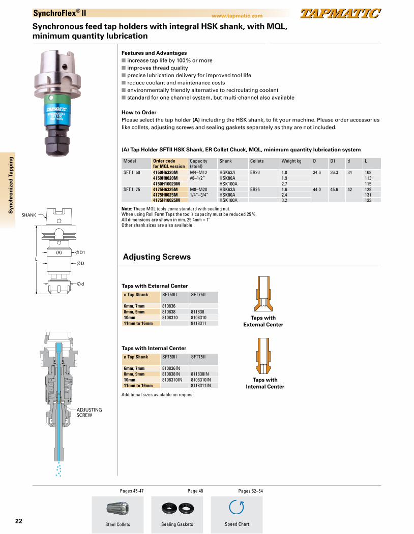
Features and Advantagesn increase tap life by 100 % or moren improves thread qualityn precise lubrication delivery for improved tool lifen reduce coolant and maintenance costsn environmentally friendly alternative to recirculating coolantn standard for one channel system, but multi-channel also available
How to OrderPlease select the tap holder (A) including the HSK shank, to fit your machine. Please order accessories like collets, adjusting screws and sealing gaskets separately as they are not included.
Synchronous feed tap holders with integral HSK shank, with MQL, minimum quantity lubrication
A A
SECTION A-A
ADJUSTINGSCREW
Draw No: 4175h6325m for catalog Date: 9-6-13 Rev:
Sealing Gaskets
Page 48Pages 45-47
Steel Collets Speed Chart
Pages 52–54
Model Order codefor MQL version
Capacity (steel)
Shank Collets Weight kg D D1 d L
SFT II 50 4150H6320M M4–M12 HSK63A ER20 1.0 34.6 36.3 34 1084150H8020M #8–1/2” HSK80A 1.9 1134150H10020M HSK100A 2.7 115
SFT II 75 4175H6325M M8–M20 HSK63A ER25 1.6 44.0 45.6 42 1284175H8025M 1/4”–3/4” HSK80A 2.4 1314175H10025M HSK100A 3.2 133
(A) Tap Holder SFTII HSK Shank, ER Collet Chuck, MQL, minimum quantity lubrication system
Note: These MQL tools come standard with sealing nut. When using Roll Form Taps the tool’s capacity must be reduced 25 %.All dimensions are shown in mm. 25.4mm = 1"Other shank sizes are also available
ø Tap Shank SFT50II SFT75II
6mm, 7mm 8108368mm, 9mm 810838 81183810mm 8108310 810831011mm to 16mm 8118311
Taps with External Center
ø Tap Shank SFT50II SFT75II
6mm, 7mm 810836IN8mm, 9mm 810838IN 811838IN10mm 8108310IN 8108310IN11mm to 16mm 8118311IN
Taps with Internal Center
A AB B
SECTION A-A SECTION B-B
Draw No:adjusting screws Date: 9-10-13 Rev:
Taps with External Center
Taps with Internal Center
A AB B
SECTION A-A SECTION B-B
Draw No:adjusting screws Date: 9-10-13 Rev:
D1
D
d
L
SHANK
COOLANT
(A)
Draw No:4175H6325 FOR CATALOG Date: 9-5-13 Rev:
Adjusting Screws
SynchroFlex® II
Additional sizes available on request.
Syn
chro
niz
ed T
app
ing
23
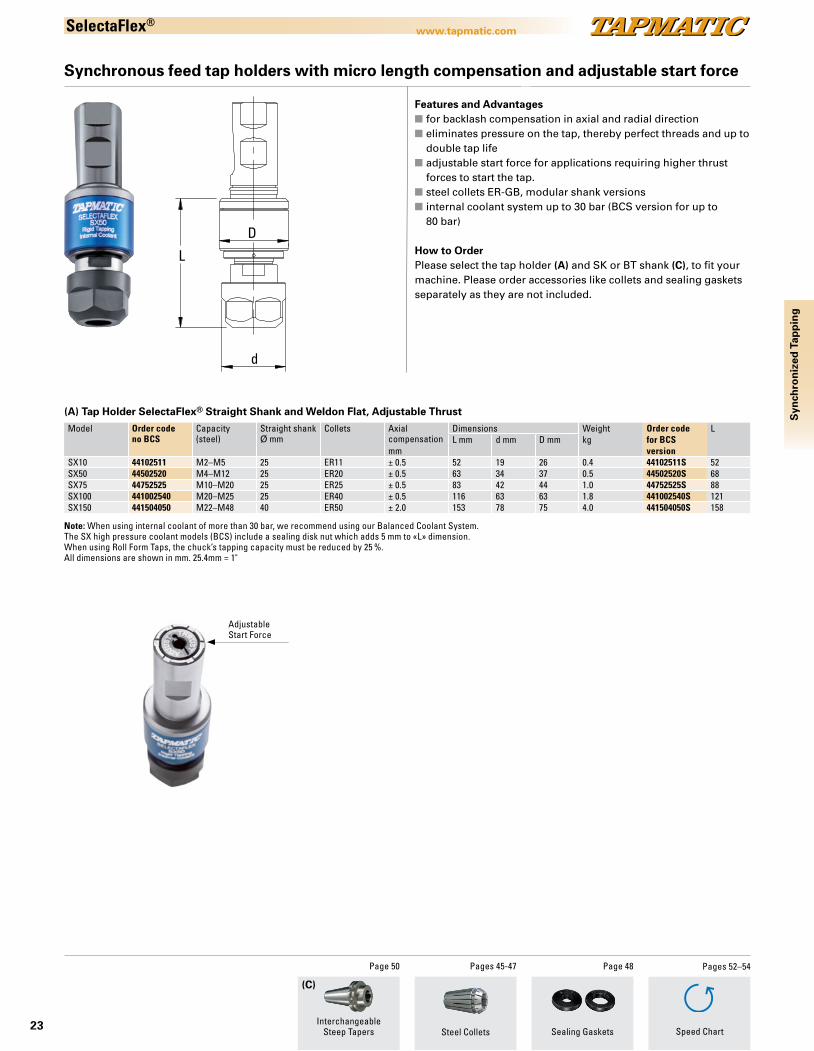
www.tapmatic.comSelectaFlex®
Model Order codeno BCS
Capacity (steel)
Straight shank Ø mm
Collets Axialcompensation
Dimensions Weight Order code LL mm d mm D mm kg for BCS
mm versionSX10 44102511 M2–M5 25 ER11 ± 0.5 52 19 26 0.4 44102511S 52SX50 44502520 M4–M12 25 ER20 ± 0.5 63 34 37 0.5 44502520S 68SX75 44752525 M10–M20 25 ER25 ± 0.5 83 42 44 1.0 44752525S 88SX100 441002540 M20–M25 25 ER40 ± 0.5 116 63 63 1.8 441002540S 121SX150 441504050 M22–M48 40 ER50 ± 2.0 153 78 75 4.0 441504050S 158
d
L
D
Synchronous feed tap holders with micro length compensation and adjustable start force
AdjustableStart Force
(C)
Sealing GasketsInterchangeable
Steep Tapers
Page 50 Page 48Pages 45-47
Steel Collets
Note: When using internal coolant of more than 30 bar, we recommend using our Balanced Coolant System. The SX high pressure coolant models (BCS) include a sealing disk nut which adds 5 mm to «L» dimension. When using Roll Form Taps, the chuck’s tapping capacity must be reduced by 25 %.All dimensions are shown in mm. 25.4mm = 1"
(A) Tap Holder SelectaFlex® Straight Shank and Weldon Flat, Adjustable Thrust
Speed Chart
Pages 52–54
Syn
chro
niz
ed T
app
ing
Features and Advantagesn for backlash compensation in axial and radial directionn eliminates pressure on the tap, thereby perfect threads and up to
double tap lifen adjustable start force for applications requiring higher thrust
forces to start the tap.n steel collets ER-GB, modular shank versionsn internal coolant system up to 30 bar (BCS version for up to
80 bar)
How to OrderPlease select the tap holder (A) and SK or BT shank (C), to fit your machine. Please order accessories like collets and sealing gaskets separately as they are not included.
24
www.tapmatic.com
Ten
sio
n/C
om
pre
ssio
n
For tapping applications on CNC machines where the revolutions per minute and feed rate are not synchronized to the tap pitch, tap holders with tension / compression float are recommended. These tap chucks rely on the machine spindle for reversal, but by providing axial float, the tap is able to follow the correct pitch, producing gage perfect threads.
Tapmatic offers a complete program of tension / compression tap chucks with a wide range of sizes, and three different tap holding options. Rubberflex multi range collets, ER collets, or Quick Change.
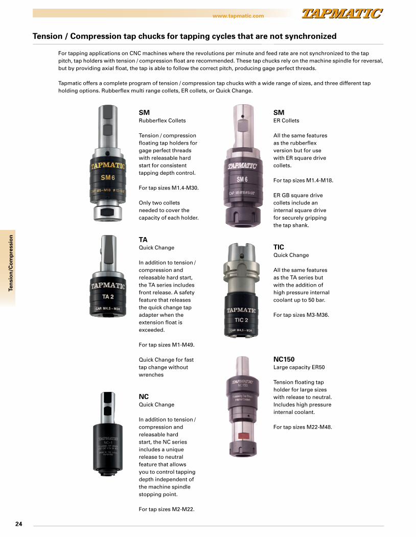
Tension / Compression tap chucks for tapping cycles that are not synchronized
SMRubberflex Collets
Tension / compression floating tap holders for gage perfect threads with releasable hard start for consistent tapping depth control.
For tap sizes M1.4-M30.
Only two collets needed to cover the capacity of each holder.
TAQuick Change
In addition to tension / compression and releasable hard start, the TA series includes front release. A safety feature that releases the quick change tap adapter when the extension float is exceeded.
For tap sizes M1-M49.
Quick Change for fast tap change without wrenches
NCQuick Change
In addition to tension / compression and releasable hard start, the NC series includes a unique release to neutral feature that allows you to control tapping depth independent of the machine spindle stopping point.
For tap sizes M2-M22.
SMER Collets
All the same features as the rubberflex version but for use with ER square drive collets.
For tap sizes M1.4-M18.
ER GB square drive collets include an internal square drive for securely gripping the tap shank.
TICQuick Change
All the same features as the TA series but with the addition of high pressure internal coolant up to 50 bar.
For tap sizes M3-M36.
NC150Large capacity ER50
Tension floating tap holder for large sizes with release to neutral. Includes high pressure internal coolant.
For tap sizes M22-M48.
25
www.tapmatic.com
Ten
sio
n/C
om
pre
ssio
n
SM
Tension/Compression tap chucks with modular straight shank and RF collet
Tapping chuck with increased tension and compression to accommodate tapping cycles that are not synchronized.
Features and Advantagesn increased tension and
compressionn releasable hard start for consistent depth controln right hand and left hand tappingn multi-range collets (RF), adjustable back
jaw for driving tap square
How to OrderPlease select the tap chuck (A) and CAT, SK or BT shank (C), to fit your application. Please order rubber flex collets separately.
Model Order code Capacity (steel) Shank ColletsRubber Flex
Tension T Compression H
SM2 023216 M1.4–M7#0 - 1/4"
16mm 21600, 21700 4.5 6023262 5/8"023202 No. 2 Morse
SM4 023420 M3–M12#6 - 1/2"
20mm 22100, 22200 7 7023475 3/4"023402 No. 2 Morse
SM6 023625 M5–M18 #10 - 3/4"
25mm 24100, 24500 11 11023610 1"023603 No. 3 Morse
SM8 023832 M10–M301/2" - 1 1/8"
32mm 26100, 26200 17 17023815 1 1/2" 023803 No. 3 Morse023804 No. 4 Morse
Model Order code Capacity (steel) Shank Collets Tension T Compression H
SM2 023216ER M1.4–M7#0 - 1/4"
16mm ER16 4.5 5023262ER 5/8"
SM4 023420ER M3–M12#6 - 1/2"
20mm ER20 7 7023475ER 3/4"
SM6 023625ER M5–M18 #10 - 3/4"
25mm ER25 11 11023610ER 1"
Model D d L Weight kgSM2 27 19 53 0.2SM4 38 27 71 0.4SM6 48 37 96 0.8SM8 63.5 57 128 2.5
Model D d L Weight kgSM2 27 28 65 0.2SM4 38 34 74 0.4SM6 48 42 94 0.8
Dimensions
Tension/Compression tap chucks with modular straight shank and ER collet
Dimensions
RF Multi-range Collets
Page 44
Speed Chart
Pages 52–54
Tapping chuck with increased tension and compression to accommodate tapping cycles that are not synchronized.
Features and Advantagesn increased tension and
compressionn releasable hard start for consistent depth controln right hand and left hand tappingn ER steel collet chuck
How to OrderPlease select the tap chuck (A) and CAT, SK or BT shank (C), to fit your application. Please order ER steel collets separately.
(C)
InterchangeableSteep Tapers
Page 50 Pages 45-47
Steel collets
Note: Additional shanks available. When using roll form taps, the tool capacity must be reduced 25%.
L D
d
SHANK SHANK(MORSE)
0023625ctlg
MJ 8-1-2016PROPRIETARY AND CONFIDENTIAL
THE INFORMATION CONTAINED IN THIS DRAWING IS THE SOLE PROPERTY OF TAPMATIC CORPORATION. ANY REPRODUCTION IN PART OR AS A WHOLE WITHOUT THE WRITTEN PERMISSION OF TAPMATIC CORPORATION IS PROHIBITED.
COMMENTS:
DRAWN:
DATENAME
DO NOT SCALE DRAWINGREV.
ADWG. NO.SIZE
TAPMATIC CORPORATIONPOST FALLS, IDAHO
DESCRIPTION
NSM6 25MM AND 3MT
SCALE -1:1
L D
d
SHANK
0023625ERctlg
MJ 8-1-16PROPRIETARY AND CONFIDENTIAL
THE INFORMATION CONTAINED IN THIS DRAWING IS THE SOLE PROPERTY OF TAPMATIC CORPORATION. ANY REPRODUCTION IN PART OR AS A WHOLE WITHOUT THE WRITTEN PERMISSION OF TAPMATIC CORPORATION IS PROHIBITED.
COMMENTS:
DRAWN:
DATENAME
DO NOT SCALE DRAWINGREV.
ADWG. NO.SIZE
TAPMATIC CORPORATIONPOST FALLS, IDAHO
DESCRIPTION
SM6 25MM ER25
SCALE -1:1

26
www.tapmatic.com
(C)
ZT
H
L2L1
d
D
Dimensions
Note: When using Roll Form Taps the chuck’s tapping capacity must be reduced by 25 %.All dimensions are shown in mm. 25.4mm = 1"
Model Order code Capacity (steel) Morse taperMT
Tap adapters Tension T Compression H Front releaseZ
TA0-MT1 490MT1 M1–M10#0–1/4"
1 Nr. 0 7.5 5 1.7TA0-MT2 490MT2 2TA1-MT2 491MT2 M3–M14
#8–9/16"2 Nr. 1 8 5 2.1
TA1-MT3 491MT3 3TA2-MT3 492MT3 M4.5–M24
5/16"–7/8"3 Nr. 2 15 8.5 2.8
TA2-MT4 492MT4 4TA2-MT5 492MT5 5TA3-MT4 493MT4 M14–M36
13/16"–1 3/8"4 Nr. 3 23.5 15 4.1
TA3-MT5 493MT5 5TA4-MT5 494MT5 M22–M48
7/8"–1 7/8"5 Nr. 4 25 16.5 5.7
TA4-MT6 494MT6 6
Model D d L1 L2TA0-MT1 29 13 62.0 43.5TA0-MT2 29 13 75.0 45.0TA1-MT2 39 19 75.0 47.0TA2-MT3 56 31 94.0 71.0TA3-MT4 81 48 117.5 105.0TA4-MT5 99 60 149.5 116.5
Tension/Compression tap chucks with morse taper and quick change
Ten
sio
n/C
om
pre
ssio
nTA
Tension/Compression tap chucks with modular straight shank and quick change
D
dZT
H
L2L1
S
TA tapping chuck with tension/compression. With its quick change spindle the taps can be changed in seconds.
Features and Advantagesn tension and compressionn releaseable hard start for consistent depth controln front release protects against damage if over extended n right hand and left hand tappingn short projection
How to OrderPlease order the tap chuck (A) and CAT, SK or BT shank (C) to fit your application. Please order tap adapters separately
Model Order code Capacity (steel) Shank Adapter Tension T Compression H Front relaseZ
TA0-016 490016 M1–M10#0 - 1/4"
16 mm Nr. 0 7.5 5 1.7TA0-020 490020 20 mm Nr. 0 7.5 5 1.7TA1-016 491016 M3–M14
#8 - 9/16"16 mm Nr. 1 8 5 2.1
TA1-020 491020 20 mm Nr. 1 8 5 2.1TA1-025 491025 25 mm Nr. 1 8 5 2.1TA2-025 492025 M4.5–M24
5/16" - 7/8"25 mm Nr. 2 15 8.5 2.8
TA2-032 492032 32 mm Nr. 2 15 8.5 2.8TA3-032 493032 M14-M36, 13/16" - 1 3/8" 32 mm Nr. 3 23.5 15 4.1TA4-040 494040 M22-M48, 7/8" - 1 7/8" 40 mm Nr. 4 25 16.5 5.7
Model D d L1 L2 TA0-016 29 13 48 38.0TA0-020 50TA1-016 39 19 49 39.0TA1-020 51TA1-025 57TA2-025 56 31 57 63.0TA2-032TA3-032 81 48 61 124.0TA4-040 99 60 71 135.5
Dimensions
Note: When using Roll Form Taps the chuck’s tapping capacity must be reduced by 25 %.
InterchangeableSteep Taper
Page 50 Pages 40-44
Quick-Change Adapters Speed Chart
Pages 52–54
How to OrderPlease select the tap chuck (A) to fit your application. Please order quick change tap adapters separately.
(A)
(A)
27
www.tapmatic.com
(C)
Ten
sio
n/C
om
pre
ssio
n
InterchangeableSteep Taper
Page 50 Pages 40-44
Quick-Change Adapters Speed Chart
Pages 52–54
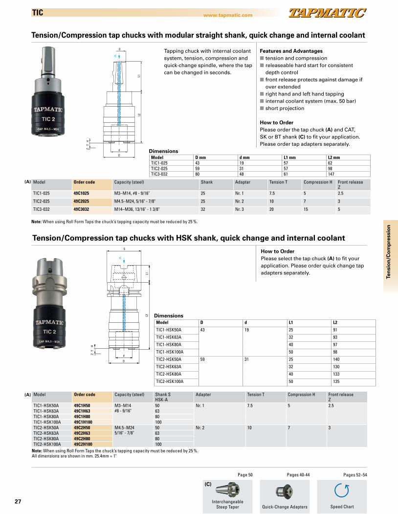
TIC
Tension/Compression tap chucks with modular straight shank, quick change and internal coolant
d
D
ZT
H
L2L1
S
ICFeatures and Advantagesn tension and compressionn releaseable hard start for consistent depth controln front release protects against damage if over extended n right hand and left hand tappingn internal coolant system (max. 50 bar)n short projection
How to OrderPlease order the tap chuck (A) and CAT, SK or BT shank (C) to fit your application. Please order tap adapters separately.
Model Order code Capacity (steel) Shank Adapter Tension T Compression H Front releaseZ
TIC1-025 49C1025 M3–M14, #8 - 9/16" 25 Nr. 1 7.5 5 2.5
TIC2-025 49C2025 M4.5–M24, 5/16" - 7/8" 25 Nr. 2 10 7 3
TIC3-032 49C3032 M14–M36, 13/16" - 1 3/8" 32 Nr. 3 20 15 5
Model D mm d mm L1 mm L2 mmTIC1-025 43 19 57 62TIC2-025 59 31 57 98TIC3-032 80 48 61 147
Dimensions
Note: When using Roll Form Taps the chuck’s tapping capacity must be reduced by 25 %.
Tension/Compression tap chucks with HSK shank, quick change and internal coolant
d
D
ZT
H
L2L1
S
IC
How to OrderPlease select the tap chuck (A) to fit your application. Please order quick change tap adapters separately.
Model Order code Capacity (steel) Shank SHSK-A
Adapter Tension T Compression H Front releaseZ
TIC1-HSK50A 49C1H50 M3–M14#8 - 9/16"
50 Nr. 1 7.5 5 2.5TIC1-HSK63A 49C1H63 63TIC1-HSK80A 49C1H80 80TIC1-HSK100A 49C1H100 100TIC2-HSK50A 49C2H50 M4.5–M24
5/16" - 7/8"50 Nr. 2 10 7 3
TIC2-HSK63A 49C2H63 63TIC2-HSK80A 49C2H80 80TIC2-HSK100A 49C2H100 100
Model D d L1 L2
TIC1-HSK50A 43 19 25 91
TIC1-HSK63A 32 93
TIC1-HSK80A 40 97
TIC1-HSK100A 50 98
TIC2-HSK50A 59 31 25 140
TIC2-HSK63A 32 130
TIC2-HSK80A 40 133
TIC2-HSK100A 50 135
Dimensions
Note: When using Roll Form Taps the chuck’s tapping capacity must be reduced by 25 %. All dimensions are shown in mm. 25.4mm = 1"
Tapping chuck with internal coolant system, tension, compression and quick-change spindle, where the tap can be changed in seconds.
(A)
(A)
28
www.tapmatic.comTe
nsi
on
/Co
mp
ress
ion
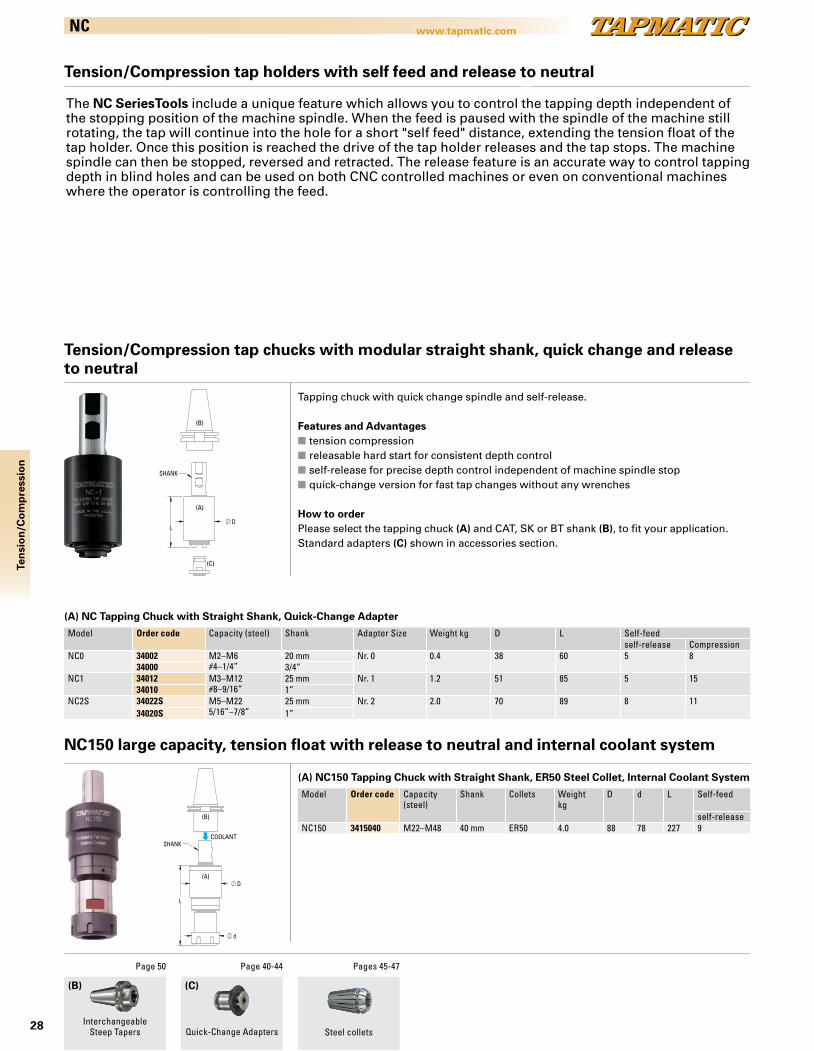
NC
(B)
InterchangeableSteep Tapers
Page 50 Page 40-44
Quick-Change Adapters
DL
SHANK
(A)
(B)
(C)
Model Order code Capacity (steel) Shank Adapter Size Weight kg D L Self-feedself-release Compression
NC0 34002 M2–M6#4–1/4”
20 mm Nr. 0 0.4 38 60 5 834000 3/4”
NC1 34012 M3–M12#8–9/16”
25 mm Nr. 1 1.2 51 85 5 1534010 1”
NC2S 34022S M5–M225/16”–7/8”
25 mm Nr. 2 2.0 70 89 8 1134020S 1”
NC150 large capacity, tension float with release to neutral and internal coolant system
(A) NC Tapping Chuck with Straight Shank, Quick-Change Adapter
Model Order code Capacity (steel)
Shank Collets Weight kg
D d L Self-feed
self-releaseNC150 3415040 M22–M48 40 mm ER50 4.0 88 78 227 9
(A) NC150 Tapping Chuck with Straight Shank, ER50 Steel Collet, Internal Coolant System
(C)
L
D
d
SHANK
(A)
(B)
COOLANT
Pages 45-47
Steel collets
Tension/Compression tap holders with self feed and release to neutral
The NC SeriesTools include a unique feature which allows you to control the tapping depth independent of the stopping position of the machine spindle. When the feed is paused with the spindle of the machine still rotating, the tap will continue into the hole for a short "self feed" distance, extending the tension float of the tap holder. Once this position is reached the drive of the tap holder releases and the tap stops. The machine spindle can then be stopped, reversed and retracted. The release feature is an accurate way to control tapping depth in blind holes and can be used on both CNC controlled machines or even on conventional machines where the operator is controlling the feed.
Tapping chuck with quick change spindle and self-release.
Features and Advantagesn tension compressionn releasable hard start for consistent depth controln self-release for precise depth control independent of machine spindle stopn quick-change version for fast tap changes without any wrenches
How to orderPlease select the tapping chuck (A) and CAT, SK or BT shank (B), to fit your application. Standard adapters (C) shown in accessories section.
Tension/Compression tap chucks with modular straight shank, quick change and release to neutral
29
www.tapmatic.com
Man
ual
Att
ach
men
ts
Manual Applications
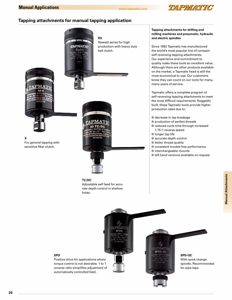
Tapping attachments for drilling and milling machines and pneumatic, hydraulic and electric spindles
Since 1952 Tapmatic has manufactured the world’s most popular line of compact self-reversing tapping attachments. Our experience and commitment to quality make these tools an excellent value. Although there are other products available on the market, a Tapmatic head is still the most economical to use. Our customers know they can count on our tools for many, many years of service.
Tapmatic offers a complete program of self-reversing tapping attachments to meet the most difficult requirements. Ruggedly built, these Tapmatic tools provide higher production rates due to:
n decrease in tap breakagen production of perfect threadsn reduced cycle time through increased
1.75 :1 reverse speedn longer tap lifen accurate depth controln better thread qualityn consistent trouble free performancen interchangeable mountsn left hand versions available on request
SPDPositive drive for applications where torque control is not desirable. 1 to 1 reverse ratio simplifies adjustment of automatically controlled feed.
Tapping attachments for manual tapping application
RXNewest series for high production with heavy duty ball clutch.
XFor general tapping with sensitive fiber clutch.
TC/DCAdjustable self feed for accu-rate depth control in shallow holes.
SPD-QCWith quick change spindle. Recommended for pipe taps.
30
www.tapmatic.comM
anu
al A
ttac
hm
ents
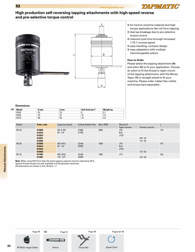
RX
High production self-reversing tapping attachments with high-speed reverseand pre-selective torque control
DL
d
n for hard to machine material and high torque applications like roll form tappingn less tap breakage due to pre-selective
torque controln reduced cycle time through increased
1.75 :1 reverse speedn easy handling, compact designn easy adaptation with multiple interchangeable arbors
How to OrderPlease select the tapping attachment (A) and arbor (C) to fit your application. Choose an arbor to fit the thread or taper mount of the tapping attachment, with the Morse Taper, R8 or straight shank to fit your machine. Please order rubber flex collets and torque bars separately .
Model Order code Capacity (steel) Collets Rubber Flex Max. RPM Mounts S LTaper mounts Thread. mounts
RX 30 013006 M1.4–M7#0 - 1/4"
2160021700
2000 JT6 116013016 B16013033 JT33013037 3/8"–24013050 1/2"–20
RX 50 015006 M3–M12#6 - 1/2"
2210022200
1500 JT6 157015016 B16015033 JT33015050 1/2"–20
RX 70 017003 M5–M18#10 - 3/4"
2410024500
1200 JT3 182017087 7/8"–20
Model D mm d mm Self-feed mm T Weight kgRX30 53 19 6 0.7RX50 76 27 10 1.8RX70 88 36 10 3.0
Dimensions
Note: When using Roll Form Taps the tool’s tapping capacity must be reduced by 25 %.Special thread mounts are also available to fit Burgmaster machines.All dimensions are shown in mm. 25.4mm = 1"
ArborsRF Multi-range Collets
Page 44 Page 51
Torque Bar
Page 49
Speed Chart
Pages 52–54
(A)
(C)
31
www.tapmatic.com
Man
ual
Att
ach
men
ts
X
Model Order code Capacity (steel) Collets Rubber Flex Max. RPM Mounts S LTaper mounts Thread. mounts
100XB 16101 M0.5–M2, #0000-0 XB 2000 JT1 9430X 10306 M1.4–M7
#0 - 1/4"2160021700
2000 JT6 11310312 B1210316 B1610333 JT3310331 5/16"–24* 10410337 3/8"–2410350 1/2"–20 11310362 5/8"–16*10375 3/4"–16*
50X 10506 M3–M12#6 - 1/2"
2210022200
1500 JT6 15310516 B1610533 JT3310537 3/8"–24 14810550 1/2"–2010562 5/8"–16*10575 3/4"–16*
70X 10703 M5–M18#10 - 1/2"
2410024500
1200 JT3 17610718 B1810750 1/2"–2010762 5/8"–16*10775 3/4"–16*10787 7/8"–20
90X 10904 M10–M301/2" - 1 1/8"
2610026200
600 JT4 21910915 1.1/2"–18
Model D d Self-feed Weight kg100XB 33 9 5 0.230X 48 19 3.5 0.550X 70 27 6 1.470X 76 36 9 2.190X 10⁵ 57 13 5.0
Self-reversing tapping attachments with high-speed reverse and pre-selective torque control
n easy handling, compact designn less tap breakage due to pre-selective
torque controln easy adaptation with multiple interchangeable arborsn reduced cycle time through increased
1.75 :1 reverse speedn only 2 Rubber Flex collets per model
required. (exception 100XB)
How to OrderPlease select the tapping attachment (A) and arbor (C) to fit your application. Choose an arbor to fit the thread or taper mount of the tapping attachment, with the Morse Taper, R8 or straight shank to fit your machine. Please order rubber flex collets and torque bars separately .
Note: X models with Quick Change or ER collet chuck are also available on request.
Dimensions
d
L D
Note: When using Roll Form Taps the tool’s tapping capacity must be reduced by 25 %.* These special thread mounts are only for Burgmaster machines.All dimensions are shown in mm. 25.4mm = 1"
ArborsRF Multi-range Collets Speed Chart
Page 44 Page 51 Pages 52–54
Torque Bar
Page 49 (C)
(A)
32
www.tapmatic.comM
anu
al A
ttac
hm
ents
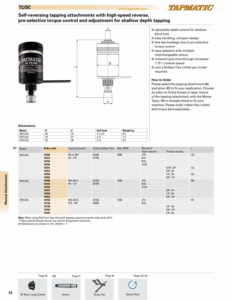
TC/DC
D
L
d
Self-reversing tapping attachments with high-speed reverse, pre-selective torque control and adjustment for shallow depth tapping
n adjustable depth control for shallow blind hole
n easy handling, compact designn less tap breakage due to pre-selective
torque controln easy adaption with multiple interchangeable arborsn reduced cycle time through increased
1.75 :1 reverse speedn only 2 Rubber Flex collets per model
required.
How to OrderPlease select the tapping attachment (A) and arbor (C) to fit your application. Choose an arbor to fit the thread or taper mount of the tapping attachment, with the Morse Taper, R8 or straight shank to fit your machine. Please order rubber flex collets and torque bars separately .
Model Order code Capacity (steel) Collets Rubber Flex Max. RPM Mounts S LTaper mounts Thread. mounts
30TC/DC 14306 M1.4–M7#0 - 1/4"
2160021700
2000 JT6 12214312 B1214316 B1614333 JT3314331 5/16"–24* 11314337 3/8"–2414350 1/2"–20 12214362 5/8"–16*
50TC/DC 14506 M3–M12#6 - 1/2"
2210022700
1500 JT6 16914516 B1614533 JT3314537 3/8"–2414550 1/2"–2014562 5/8"–16*
70TC/DC 14703 M5–M18#10 - 5/8"
2410024500
1200 JT3 19114718 B1814750 1/2"–2014762 5/8"–16*14787 7/8"–20
Model D d Self-feed Weight kg30TC/DC 48 19 1.5–3.5 0.550TC/DC 70 27 2–6 1.270TC/DC 76 36 3–9 2.3
Dimensions
Note: When using Roll Form Taps the tool’s tapping capacity must be reduced by 25 %.* These special thread mounts are only for Burgmaster machines.All dimensions are shown in mm. 25.4mm = 1"
ArborsRF Multi-range Collets
Page 44 Page 51
Torque Bar
Page 49
Speed Chart
Pages 52–54
(A)
(C)
33
www.tapmatic.com
Man
ual
Att
ach
men
ts
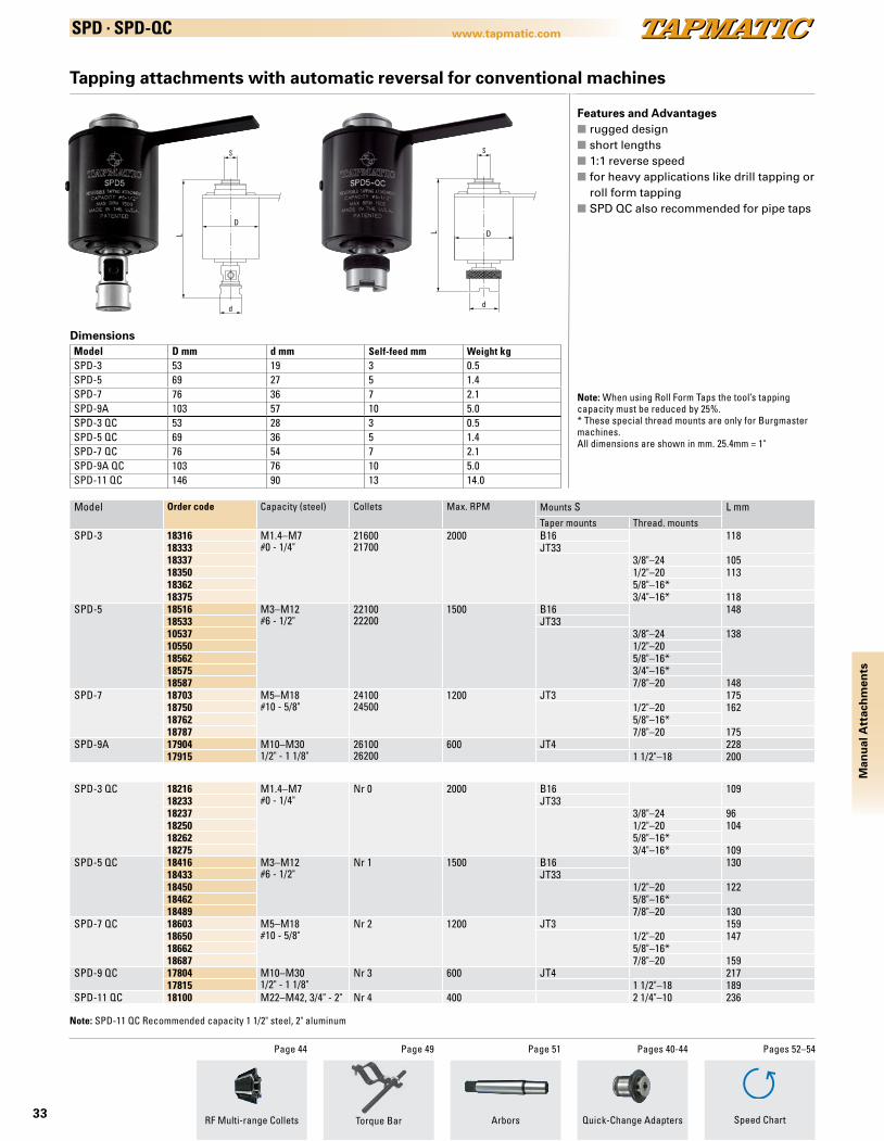
SPD . SPD-QC
Model Order code Capacity (steel) Collets Max. RPM Mounts S L mmTaper mounts Thread. mounts
SPD-3
18316 M1.4–M7#0 - 1/4"
2160021700
2000 B16 11818333 JT3318337 3/8"–24 10518350 1/2"–20 11318362 5/8"–16*18375 3/4"–16* 118
SPD-5
18516 M3–M12#6 - 1/2"
2210022200
1500 B16 14818533 JT3310537 3/8"–24 13810550 1/2"–2018562 5/8"–16*18575 3/4"–16*18587 7/8"–20 148
SPD-7
18703 M5–M18#10 - 5/8"
2410024500
1200 JT3 17518750 1/2"–20 16218762 5/8"–16*18787 7/8"–20 175
SPD-9A 17904 M10–M301/2" - 1 1/8"
2610026200
600 JT4 22817915 1 1/2"–18 200
SPD-3 QC 18216 M1.4–M7#0 - 1/4"
Nr 0 2000 B16 10918233 JT3318237 3/8"–24 9618250 1/2"–20 10418262 5/8"–16*18275 3/4"–16* 109
SPD-5 QC 18416 M3–M12#6 - 1/2"
Nr 1 1500 B16 13018433 JT3318450 1/2"–20 12218462 5/8"–16*18489 7/8"–20 130
SPD-7 QC 18603 M5–M18#10 - 5/8"
Nr 2 1200 JT3 15918650 1/2"–20 14718662 5/8"–16*18687 7/8"–20 159
SPD-9 QC 17804 M10–M301/2" - 1 1/8"
Nr 3 600 JT4 21717815 1 1/2"–18 189
SPD-11 QC 18100 M22–M42, 3/4" - 2" Nr 4 400 2 1/4"–10 236
D
L
d
DL
d
Model D mm d mm Self-feed mm Weight kgSPD-3 53 19 3 0.5SPD-5 69 27 5 1.4SPD-7 76 36 7 2.1SPD-9A 103 57 10 5.0SPD-3 QC 53 28 3 0.5SPD-5 QC 69 36 5 1.4SPD-7 QC 76 54 7 2.1SPD-9A QC 103 76 10 5.0SPD-11 QC 146 90 13 14.0
Dimensions
Tapping attachments with automatic reversal for conventional machines
Features and Advantagesn rugged designn short lengthsn 1:1 reverse speedn for heavy applications like drill tapping or
roll form tappingn SPD QC also recommended for pipe taps
Note: When using Roll Form Taps the tool’s tapping capacity must be reduced by 25%.* These special thread mounts are only for Burgmaster machines.All dimensions are shown in mm. 25.4mm = 1"
RF Multi-range Collets
Page 44
Arbors
Page 51 Pages 40-44
Quick-Change AdaptersTorque Bar
Page 49 Pages 52–54
Speed Chart
Note: SPD-11 QC Recommended capacity 1 1/2" steel, 2" aluminum
34
www.tapmatic.comTa
pW
rite
r®TapWriter®
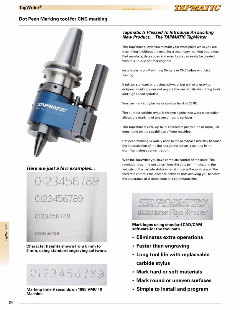
Dot Peen Marking tool for CNC marking
Character heights shown from 6 mm to 2 mm, using standard engraving software.
Marking time 9 seconds on 1995 VMC 40 Machine.
Mark logos using standard CAD/CAM software for the tool path.
• Eliminates extra operations
• Faster than engraving
• Long tool life with replaceable
carbide stylus
• Mark hard or soft materials
• Mark round or uneven surfaces
• Simple to install and program
Here are just a few examples...
Tapmatic Is Pleased To Introduce An Exciting New Product.... The TAPMATIC TapWriter.
The TapWriter allows you to mark your work piece while you are machining it without the need for a secondary marking operation. Part numbers, date codes and even logos can easily be created with this unique dot marking tool.
Installs easily on Machining Centers or CNC lathes with Live Tooling.
It utilizes standard engraving software, but unlike engraving,dot-peen marking does not require the use of delicate cutting tools and high speed spindles.
You can mark soft plastics or steel as hard as 55 RC.
The durable carbide stylus is thrown against the work piece which allows the marking of uneven or round surfaces.
The TapWriter is Fast. Up to 80 characters per minute or more just depending on the capabilities of your machine.
Dot peen marking is widely used in the aerospace industry because the cross section of the dot has gentle curves, resulting in no significant stress concentration.
With the TapWriter you have complete control of the mark. The revolutions per minute determines the dots per minute, and the velocity of the carbide stylus when it impacts the work piece. The feed rate controls the distance between dots allowing you to select the apperance of discrete dots or a continuous line.
35
www.tapmatic.com
Tap
Wri
ter®
TapWriter®
10879
19
DISTANCECENTER
STOPBLOCK
SHANK
57 42L3
16
(A) (B)
(C)
10879
19
SHANKTORQUEBAR
STOPARM
5742
29
(C)
(A) (B)
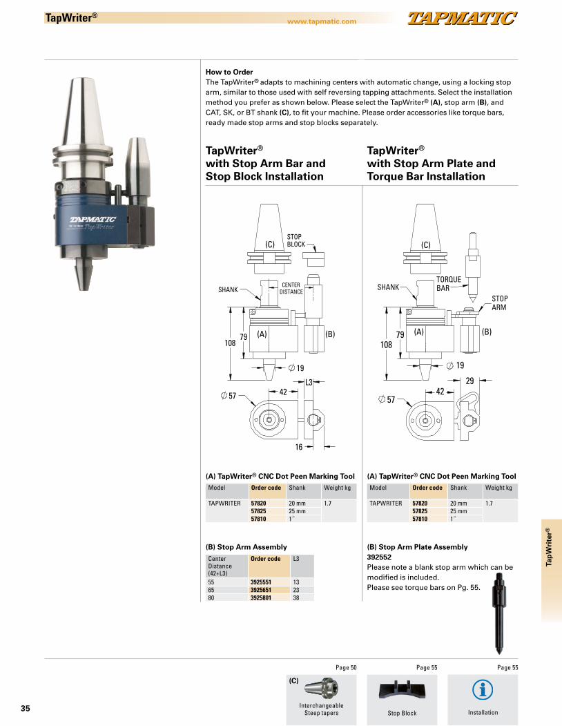
Center Distance(42+L3)
Order code L3
55 3925551 1365 3925651 2380 3925801 38
Model Order code Shank Weight kg
TAPWRITER 57820 20 mm 1.757825 25 mm57810 1˝
Model Order code Shank Weight kg
TAPWRITER 57820 20 mm 1.757825 25 mm57810 1˝
How to OrderThe TapWriter® adapts to machining centers with automatic change, using a locking stop arm, similar to those used with self reversing tapping attachments. Select the installation method you prefer as shown below. Please select the TapWriter® (A), stop arm (B), and CAT, SK, or BT shank (C), to fit your machine. Please order accessories like torque bars, ready made stop arms and stop blocks separately.
TapWriter® with Stop Arm Plate and Torque Bar Installation
(A) TapWriter® CNC Dot Peen Marking Tool
TapWriter® with Stop Arm Bar and Stop Block Installation
(B) Stop Arm Plate Assembly392552Please note a blank stop arm which can be modified is included. Please see torque bars on Pg. 55.
(B) Stop Arm Assembly
(A) TapWriter® CNC Dot Peen Marking Tool
(C)
InterchangeableSteep tapers
Page 50
Installation
Page 55
Stop Block
Page 55
36
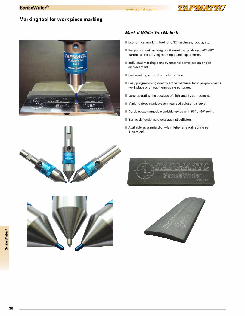
www.tapmatic.comScribeWriter®
Marking tool for work piece marking
Mark It While You Make It.
n Economical marking tool for CNC machines, robots, etc.
n For permanent marking of different materials up to 62 HRC hardness and varying marking planes up to 5mm.
n Individual marking done by material compression and or displacement.
n Fast marking without spindle rotation.
n Easy programming directly at the machine, from programmer’s work place or through engraving software.
n Long operating life because of high-quality components.
n Marking depth variable by means of adjusting sleeve.
n Durable, exchangeable carbide stylus with 60° or 90° point.
n Spring deflection protects against collision.
n Available as standard or with higher strength spring set (H version).
Scr
ibeW
rite
r®

37
www.tapmatic.com
Scr
ibeW
rite
r®
Marking tool for work piece marking
ScribeWriter®
InterchangeableSteep tapers
Page 50
How to OrderPlease select the ScribeWriter® with shank and tip angle to fit your application.
Available with standard or with a higher strength spring set (H version) for harder materials. Specify by Adding "H" to part number shown below.
ScribeWriter®
Mark It While You Make It.
Order code Shank Tip DimensionsL D
57901-90 1" 90° 83 mm 30 mm57901-60 1" 60° 83 mm 30 mm57925-90 25 mm 90° 83 mm 30 mm57925-60 25 mm 60° 83 mm 30 mm57920-90 20 mm 90° 83 mm 30 mm57920-60 20 mm 60° 83 mm 30 mm57916-90 16 mm 90° 83 mm 30 mm57916-60 16 mm 60° 83 mm 30 mm
5791608Assy 90° Replacement stylus, complete5791611Assy 60° Replacement stylus, complete
Stylus
90° blue60° gold
D
Shank
L
Note: For ScribeWriter with higher strength spring set (H version), for harder materials, specify by adding "H" to part number, for example 57925-90H.
38
Mar
kin
g H
ead
www.tapmatic.com
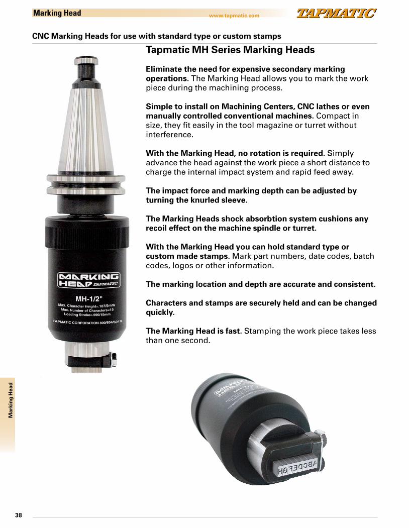
CNC Marking Heads for use with standard type or custom stamps
Tapmatic MH Series Marking Heads
Eliminate the need for expensive secondary marking operations. The Marking Head allows you to mark the work piece during the machining process.
Simple to install on Machining Centers, CNC lathes or even manually controlled conventional machines. Compact in size, they fit easily in the tool magazine or turret without interference.
With the Marking Head, no rotation is required. Simply advance the head against the work piece a short distance to charge the internal impact system and rapid feed away.
The impact force and marking depth can be adjusted by turning the knurled sleeve.
The Marking Heads shock absorbtion system cushions any recoil effect on the machine spindle or turret.
With the Marking Head you can hold standard type or custom made stamps. Mark part numbers, date codes, batch codes, logos or other information.
The marking location and depth are accurate and consistent.
Characters and stamps are securely held and can be changed quickly.
The Marking Head is fast. Stamping the work piece takes less than one second.
Marking Head
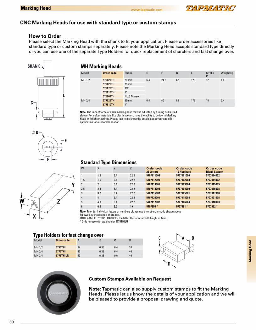
39
Mar
kin
g H
ead
www.tapmatic.com
Model Order code Shank E F D L StrokeC
Weight kg
MH 1/2 575020TH 20 mm 6.4 24.5 62 128 12 1.6575025TH 25 mm575075TH 3/4˝575010TH 1"575003TH No.3 Morse
MH 3/4 577525TH 25mm 6.4 40 86 172 18 3.4577510TH 1"
Model Order code A B C D
MH 1/2 5750THI 24 6.35 6.4 24MH 3/4 5775THI 40 6.35 6.4 40MH 3/4 5775THILG 40 6.35 9.6 40
W X Y Z Order code26 Letters
Order code10 Numbers
Order codeBlank Spacer
1 1.6 6.4 22.2 5707111006 5707101000 57070140021.5 1.6 6.4 22.2 5707112009 5707102003 57070140022 2 6.4 22.2 5707113001 5707103006 57070150052.5 2.4 6.4 22.2 5707114004 5707104009 57070160083 3.2 6.4 22.2 5707115007 5707105001 57070170004 4 6.4 22.2 5707120001 5707118008 57070210085 4.8 6.4 22.2 5707117002 5707106004 57070180036 6.5 9.5 19 5707950 * 5707951 * 5707952 *
CNC Marking Heads for use with standard type or custom stamps
L
C
D
F
E
SHANK
A B
D
C
Draw No:MH Insert for CAT Date: 102110 Rev:
Y
Z
X
W
Marking Head
MH Marking Heads
Standard Type Dimensions
Type Holders for fast change over
How to OrderPlease select the Marking Head with the shank to fit your application. Please order accessories like standard type or custom stamps separately. Please note the Marking Head accepts standard type directly or you can use one of the separate Type Holders for quick replacement of charcters and fast change over.
Note: The impact force of each marking head may be adjusted by turning its knurled sleeve. For softer materials like plastic we also have the ability to deliver a Marking Head with lighter springs. Please just let us know the details about your specific application for a recommendation.
Note: To order individual letters or numbers please use the set order code shown above followed by the desired character.FOR EXAMPLE: "5707111006D" for the letter D character with height of 1mm.* Only for use with type holder 5775THILG
Custom Stamps Available on Request
Note: Tapmatic can also supply custom stamps to fit the Marking Heads. Please let us know the details of your application and we will be pleased to provide a proposal drawing and quote.

40
Acc
esso
ries
www.tapmatic.comP
d
L1L3L2
D
Ø
IC
Quick-change adapters, positive drive inch sizes
For quick change tap chucks TA, TIC, NC and SPD QC, with or without internal coolant system.
Features and Advantagesn equally appropriate for taps with internal coolantn no pre-selective torque driven suitable for right and left hand tapping
Model Adapter Size Dimensionsd mm L1 mm D mm L2 mm
P0 0 13 26.5 22 7P1 1 19 28.5 30 7P2 2 31 46.5 48 11P3 3 48 68.5 70 14P4 4 60 105.0 92 42
Product range – AdaptersTap Shank
Ø inchSquare inch
Order codeP0
Order codeP1
Order codeP2
Order codeP3
Order codeP4
#0 - #6 .141 .110 1001 1006#8 .168 .131 1002 1007#10 .194 .152 1003 1008 1016#12 .220 .165 1004 10091/4" .255 .191 1005 1010 10175/16" .318 .238 1012 10183/8" .381 .286 1013 10197/16" .323 .242 1014 10201/2" .367 .275 1015 10219/16" .429 .322 10155 10221/8" Pipe .313 .234 10166 102661/8" Pipe .438 .328 10177 102775/8" .480 .360 102311/16" .542 .406 10243/4" .590 .442 1025 1039213/16" .652 .489 1026 10317/8" .697 .523 1027 10321/4" Pipe .562 .421 102883/8" Pipe .700 .531 10299 103861/2" Pipe .687 .515 10300 1038715/16" .760 .570 10331" .800 .600 1034 103911 1/8" .896 .672 1035 103931 1/4" 1.021 .766 1036 10391 3/8" 1.108 .831 1037 10403/4" Pipe .906 .679 10388 104401" Pipe 1.125 .843 10389 104421 1/2" 1.233 .925 10411 5/8" 1.305 .979 10421 3/4" 1.430 1.072 10431 7/8" 1.519 1.139 104351 1/4" Pipe 1.312 .984 104441 1/2" Pipe 1.500 1.125 104552" 1.644 1.233 1044

41
Acc
esso
ries
www.tapmatic.comP
d
L1L3L2
D
Ø
IC
Quick-change adapters, positive drive metric sizes
For quick change tap chucks TA, TIC, NC and SPD QC with or without internal coolant system.
Features and Advantagesn equally appropriate for taps with internal coolantn no pre-selective torque driven suitable for right and left hand tapping
Model Adapter Size Dimensionsd mm L1 mm D mm L2 mm
P0 0 13 26.5 22 7P1 1 19 28.5 30 7P2 2 31 46.5 48 11P3 3 48 68.5 70 14P4 4 60 105.0 92 42
Quick change adapters, positive drive metric sizesTap Shank
ØmmSquare mm
Order codeP0
Order codeP1
Order codeP2
Order codeP3
Order codeP4
M2, M2.5, M4 2.8 2.1 P0-028021M3, M5 3.5 2.7 P0-035027 P1-035027M3.5 4 3 P0-040030 P1-040030M4 4.5 3.4 P0-045034 P1-045034M4, M4.5 5 4 P0-050040 P1-050040M4.5, M5, M6, M8 6 4.9 P0-060049 P1-060049 P2-060049M8 8 6.2 P0-080062* P1-080062 P2-080062M7, M9, M10 7 5.5 P0-070055* P1-070055 P2-070055M12 9 7 P1-090070 P2-090070M10 10 8 P1-100080 P2-100080M14 11 9 P1-110090 P2-110090 P3-110090M16 12 9 P2-120090 P3-120090M18 14 11 P2-140110 P3-140110M20 16 12 P2-160120 P3-160120M22, M24, M25, M26 18 14.5 P2-180145 P3-180145 P4-180145M27, M28 20 16 P3-200160 P4-200160M30, M32 22 18 P3-220180 P4-220180M33 25 20 P3-250200 P4-250200M34, M35, M36, M38 28 22 P3-280220 P4-280220M39, M40, M42 32 24 P4-320240M45, M48, M50 36 29 P4-360290
Note: other sizes available on request.
Note: Version with (*) only suitable for light processing
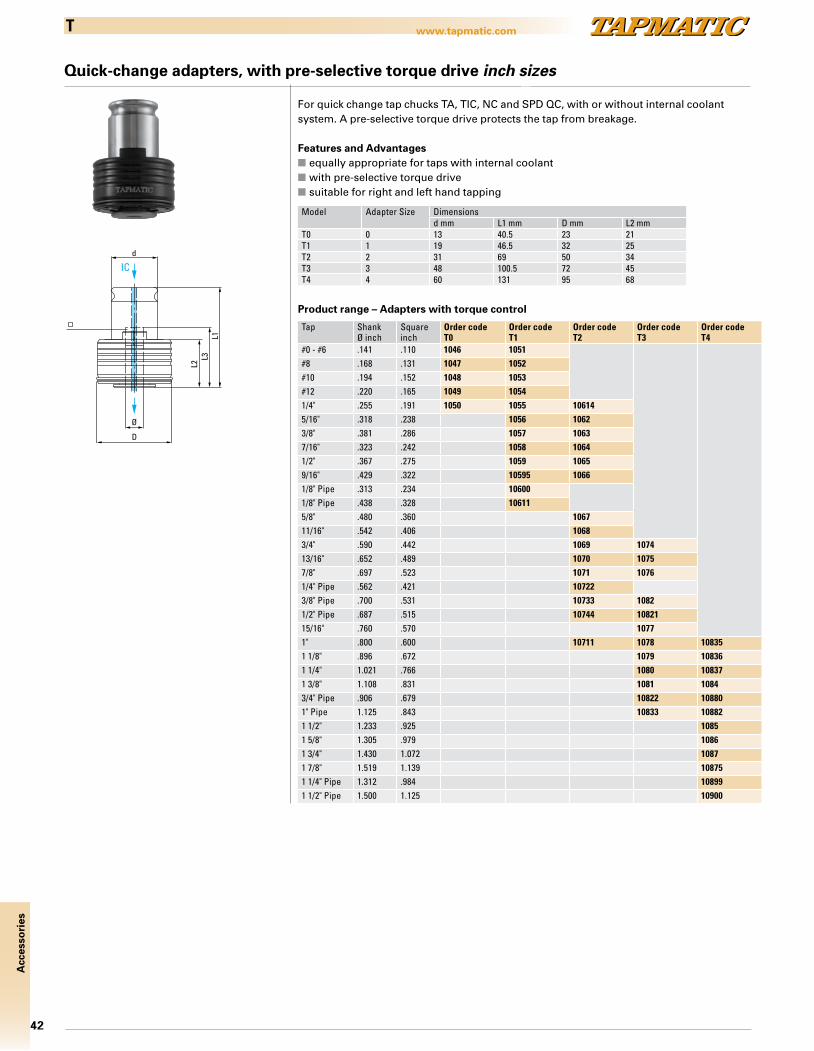
42
Acc
esso
ries
www.tapmatic.comT
Quick-change adapters, with pre-selective torque drive inch sizes
d
IC
L2L3
L1
D
Ø
For quick change tap chucks TA, TIC, NC and SPD QC, with or without internal coolant system. A pre-selective torque drive protects the tap from breakage.
Features and Advantagesn equally appropriate for taps with internal coolantn with pre-selective torque driven suitable for right and left hand tapping
Model Adapter Size Dimensionsd mm L1 mm D mm L2 mm
T0 0 13 40.5 23 21T1 1 19 46.5 32 25T2 2 31 69 50 34T3 3 48 100.5 72 45T4 4 60 131 95 68
Product range – Adapters with torque control
Tap ShankØ inch
Squareinch
Order codeT0
Order codeT1
Order codeT2
Order codeT3
Order codeT4
#0 - #6 .141 .110 1046 1051#8 .168 .131 1047 1052#10 .194 .152 1048 1053#12 .220 .165 1049 10541/4" .255 .191 1050 1055 106145/16" .318 .238 1056 10623/8" .381 .286 1057 10637/16" .323 .242 1058 10641/2" .367 .275 1059 10659/16" .429 .322 10595 10661/8" Pipe .313 .234 106001/8" Pipe .438 .328 106115/8" .480 .360 106711/16" .542 .406 10683/4" .590 .442 1069 107413/16" .652 .489 1070 10757/8" .697 .523 1071 10761/4" Pipe .562 .421 107223/8" Pipe .700 .531 10733 10821/2" Pipe .687 .515 10744 1082115/16" .760 .570 10771" .800 .600 10711 1078 108351 1/8" .896 .672 1079 108361 1/4" 1.021 .766 1080 108371 3/8" 1.108 .831 1081 10843/4" Pipe .906 .679 10822 108801" Pipe 1.125 .843 10833 108821 1/2" 1.233 .925 10851 5/8" 1.305 .979 10861 3/4" 1.430 1.072 10871 7/8" 1.519 1.139 108751 1/4" Pipe 1.312 .984 108991 1/2" Pipe 1.500 1.125 10900

43
Acc
esso
ries
www.tapmatic.comT
Quick-change adapters, with pre-selective torque drive metric sizes
d
IC
L2L3
L1
D
Ø
For quick change tap chucks TA, TIC, NC and SPD QC, with or without internal coolant system. A pre-selective torque drive protects the tap from breakage.
Features and Advantagesn equally appropriate for taps with internal coolantn with pre-selective torque driven suitable for right and left hand tapping
Model Adapter Size Dimensionsd mm L1 mm D mm L2 mm
T0 0 13 40.5 23 21T1 1 19 46.5 32 25T2 2 31 69 50 34T3 3 48 100.5 72 45T4 4 60 131 95 68
Product range – Adapters with torque control
Tap ShankØ mm
Squaremm
Order codeT0
Order codeT1
Order codeT2
Order codeT3
Order codeT4
M2, M2.5, M4 2.8 2.1 TC0-028021M3, M5 3.5 2.7 TC0-035027 TC1-035027M3.5 4 3 TC0-040030 TC1-040030M4 4.5 3.4 TC0-045034 TC1-045034M4, M4.5 5 4 TC0-050040 TC1-050040M4.5, M5, M6, M8 6 4.9 TC0-060049 TC1-060049 TC2-060049M8 8 6.2 TC0-080062* TC1-080062 TC2-080062M7, M9, M10 7 5.5 TC0-070055* TC1-070055 TC2-070055M12 9 7 TC1-090070 TC2-090070M10 10 8 TC1-100080 TC2-100080M14 11 9 TC1-110090 TC2-110090 TC3-110090M16 12 9 TC2-120090 TC3-120090M18 14 11 TC2-140110 TC3-140110M20 16 12 TC2-160120 TC3-160120M22, M24, M25, M26 18 14.5 TC2-180145 TC3-180145 TC4-180145M27, M28 20 16 TC3-200160 TC4-200160M30, M32 22 18 TC3-220180 TC4-220180M33 25 20 TC3-250200 TC4-250200M34, M35, M36, M38 28 22 TC3-280220 TC4-280220M39, M40, M42 32 24 TC4-320240M45, M48, M50 36 29 TC4-360290
Note: Version with (*) only suitable for light processing
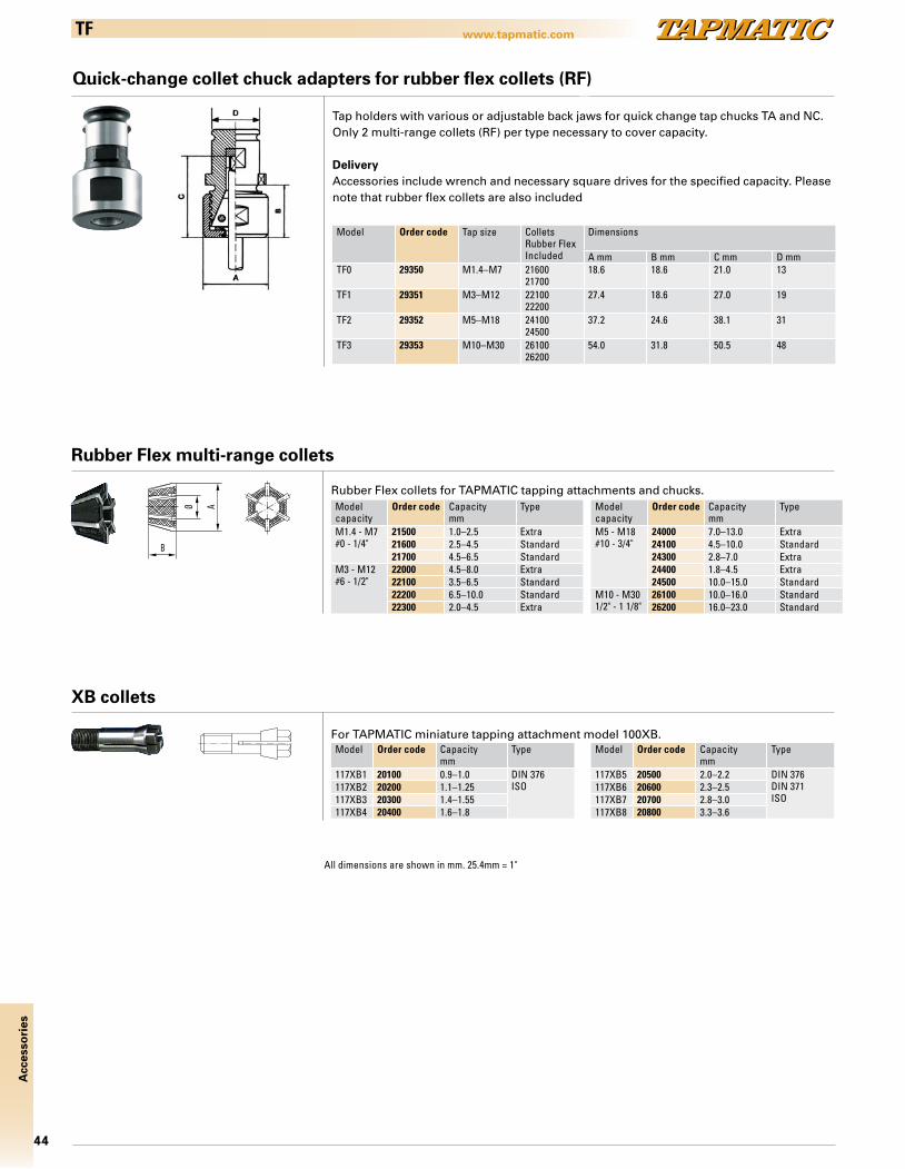
44
Acc
esso
ries
www.tapmatic.com
All dimensions are shown in mm. 25.4mm = 1"
TF
Quick-change collet chuck adapters for rubber flex collets (RF)
Model Order code Tap size ColletsRubber FlexIncluded
Dimensions
A mm B mm C mm D mmTF0 29350 M1.4–M7 21600
2170018.6 18.6 21.0 13
TF1 29351 M3–M12 2210022200
27.4 18.6 27.0 19
TF2 29352 M5–M18 2410024500
37.2 24.6 38.1 31
TF3 29353 M10–M30 2610026200
54.0 31.8 50.5 48
Tap holders with various or adjustable back jaws for quick change tap chucks TA and NC. Only 2 multi-range collets (RF) per type necessary to cover capacity.
DeliveryAccessories include wrench and necessary square drives for the specified capacity. Please note that rubber flex collets are also included
° °
Rubber Flex multi-range collets
Rubber Flex collets for TAPMATIC tapping attachments and chucks.Modelcapacity
Order code Capacitymm
Type
M1.4 - M7#0 - 1/4"
21500 1.0–2.5 Extra21600 2.5–4.5 Standard21700 4.5–6.5 Standard
M3 - M12#6 - 1/2"
22000 4.5–8.0 Extra22100 3.5–6.5 Standard22200 6.5–10.0 Standard22300 2.0–4.5 Extra
Modelcapacity
Order code Capacity mm
Type
M5 - M18#10 - 3/4"
24000 7.0–13.0 Extra24100 4.5–10.0 Standard24300 2.8–7.0 Extra24400 1.8–4.5 Extra24500 10.0–15.0 Standard
M10 - M301/2" - 1 1/8"
26100 10.0–16.0 Standard26200 16.0–23.0 Standard
XB collets
For TAPMATIC miniature tapping attachment model 100XB.Model Order code Capacity
mmType
117XB1 20100 0.9–1.0 DIN 376ISO117XB2 20200 1.1–1.25
117XB3 20300 1.4–1.55117XB4 20400 1.6–1.8
Model Order code Capacity mm
Type
117XB5 20500 2.0–2.2 DIN 376DIN 371ISO
117XB6 20600 2.3–2.5117XB7 20700 2.8–3.0117XB8 20800 3.3–3.6

45
Acc
esso
ries
www.tapmatic.comER-GB
Steel collets ER-GB with inner square metric sizes
Collets to DIN 6499B with inner square for positive drive of tap square.
ER16GBA = 17.0 mm B = 27.5 mm
Order code Shank mm Square mmGB116040 4.0 3.15/3.2GB116045 4.5 3.4GB116050 5.0 4.0GB116053 5.5 4.3GB116055 5.5 4.5GB116065 6.0 4.5GB116060 6.0 4.9GB116062 6.2 5.0GB116063 6.3 5.0GB116070 7.0 5.5GB116071 7.1 5.6GB116080 8.0 6.2/6.3GB116085 8.5 6.5GB116090 9.0 7.0/7.1
ER20GBA = 21.0 mm B = 31.5 mm
Order code Shank mm Square mmGB120040 4.0 3.15/3.2GB120045 4.5 3.4GB120050 5.0 4.0GB120053 5.5 4.3GB120055 5.5 4.5GB120065 6.0 4.5GB120060 6.0 4.9GB120062 6.2 5.0GB120063 6.3 5.0GB120070 7.0 5.5GB120071 7.1 5.6GB120080 8.0 6.2/6.3GB120085 8.5 6.5GB120090 9.0 7.0/7.1GB120100 10.0 8.0GB120105 10.5 8.0GB120110 11.0 9.0GB120112 11.2 9.0GB120120 12.0 9.0
ER25GBA = 26.0 mm B = 34.0 mm
Order code Shank mm Square mmGB125040 4.0 3.15/3.2GB125045 4.5 3.4GB125050 5.0 4.0GB125053 5.5 4.3GB125055 5.5 4.5GB125065 6.0 4.5GB125060 6.0 4.9GB125062 6.2 5.0GB125063 6.3 5.0GB125070 7.0 5.5GB125071 7.1 5.6GB125080 8.0 6.2/6.3GB125085 8.5 6.5GB125090 9.0 7.0/7.1GB125100 10.0 8.0GB125105 10.5 8.0GB125110 11.0 9.0GB125112 11.2 9.0GB125120 12.0 9.0GB125125 12.5 10.0GB125140 14.0 11.0/11.2GB125150 15.0 12.0GB125160 16.0 12.0
ER32GBA = 33.0 mm B = 40.0 mm
Order code Shank mm Square mmGB132040 4.0 3.15/3.2GB132045 4.5 3.4GB132050 5.0 4.0GB132053 5.5 4.3GB132055 5.5 4.5GB132065 6.0 4.5GB132060 6.0 4.9GB132062 6.2 5.0GB132063 6.3 5.0GB132070 7.0 5.5GB132071 7.1 5.6GB132080 8.0 6.2/6.3GB132085 8.5 6.5GB132090 9.0 7.0/7.1GB132100 10.0 8.0GB132105 10.5 8.0GB132110 11.0 9.0GB132112 11.2 9.0GB132120 12.0 9.0GB132125 12.5 10.0GB132140 14.0 11.0/11.2GB132150 15.0 12.0GB132160 16.0 12.0GB132170 17.0 13.0GB132180 18.0 14.0/14.5GB132200 20.0 16.0
ER40GBA = 41.0 mm B = 46.0 mm
Order code Shank mm Square mmGB140065 6.0 4.5GB140060 6.0 4.9GB140062 6.2 5.0GB140063 6.3 5.0GB140070 7.0 5.5GB140071 7.1 5.6GB140080 8.0 6.2/6.3GB140085 8.5 6.5GB140090 9.0 7.0/7.1GB140100 10.0 8.0GB140105 10.5 8.0GB140110 11.0 9.0GB140112 11.2 9.0GB140120 12.0 9.0GB140125 12.5 10.0GB140140 14.0 11.0/11.2GB140150 15.0 12.0GB140160 16.0 12.0GB140170 17.0 13.0GB140180 18.0 14.0/14.5GB141200 20.0 16.0GB141220 22.0 18.0
ER50GBA = 60.0 mm B = 52.0 mm
Order code Shank mm Square mmGB150220 22.0 18.0GB150250 25.0 20.0GB150280 28.0 22.0GB150320 32.0 24.0
ER11GBA = 11.5 mm B = 17.0 mm
Order code Shank mm Square mmGB111028 2.8 2.1GB111035 3.5 2.7GB111045 4.5 3.4GB111050 5.0 4.0GB111060 6.0 4.9

46
Acc
esso
ries
www.tapmatic.comER-GB
Steel collets ER-GB with inner square inch sizes
ER11GB
Order code Tap size Shank inch Square inch A B L221000 #0 - #6 .141 .110 .444 .708 .47221001 #8 .168 .131 .444 .708 .55121002 #10 .194 .152 .444 .708 .551
ER16GB
Order code Tap size Shank inch Square inch A B L221004 #0 - #6 .141 .110 .629 1.083 .70921005 #8 .168 .131 .629 1.083 .70921006 #10 .194 .152 .629 1.083 .70921008 #12 .220 .165 .629 1.083 .70921010 1/4" .255 .191 .629 1.083 .70921012 5/16" .318 .238 .629 1.083 .86621014 7/16" .323 .242 .629 1.083 .866
ER20GB
Order code Tap size Shank inch Square inch A B L221019 #8 .168 .131 .787 1.240 .70921020 #10 .194 .152 .787 1.240 .70921021 #12 .220 .165 .787 1.240 .70921022 1/4" .255 .191 .787 1.240 .70921023 5/16" .318 .238 .787 1.240 .86621024 7/16" .323 .242 .787 1.240 .86621025 1/2" .367 .275 .787 1.240 .86621026 3/8" .381 .286 .787 1.240 .86621027 1/16" Pipe .3125 .234 .787 1.240 .866
ER32GB
Order code Tap size Shank inch Square inch A B L221047 1/4" .255 .191 1.260 1.575 .70921048 5/16" .318 .238 1.260 1.575 .86621049 7/16" .323 .242 1.260 1.575 .86621052 3/8" .381 .286 1.260 1.575 .86621050 1/2" .367 .275 1.260 1.575 .86621054 9/16" .429 .322 1.260 1.575 .98421058 5/8" .480 .360 1.260 1.575 .98421060 11/16" .542 .406 1.260 1.575 .98421064 3/4" .590 .442 1.260 1.575 .98421066 13/16" .652 .489 1.260 1.575 .98421068 7/8" .697 .523 1.260 1.575 .98421056 1/8" Pipe .437 .328 1.260 1.575 .98421062 1/4" Pipe .562 .421 1.260 1.575 .98421067 1/2" Pipe .687 .515 1.260 1.575 .98421070 1" .800 .600 1.260 1.575 1.102
ER40GB
Order code Tap size Shank inch Square inch A B L221104 1/2" .367 .275 1.575 1.811 .86621105 3/8" .381 .286 1.575 1.811 .86621106 9/16" .429 .322 1.575 1.811 .98421107 5/8" .480 .360 1.575 1.811 .98421108 11/16" .542 .406 1.575 1.811 .98421109 3/4" .590 .442 1.575 1.811 .98421110 13/16" .652 .489 1.575 1.811 .98421111 7/8" .697 .523 1.575 1.811 .98421112 15/16" .760 .570 1.575 1.811 .98421113 1" .800 .600 1.575 1.811 1.10221117 1 1/8" .896 .672 1.575 1.811 1.10221114 1/4" Pipe .562 .421 1.575 1.811 .98421115 3/8" Pipe .700 .531 1.575 1.811 .98421116 1/2" Pipe .687 .515 1.575 1.811 .984
ER25GB
Order code Tap size Shank inch Square inch A B L221031 1/4" .255 .191 .984 1.338 .70921029 5/16" .318 .238 .984 1.338 .86621030 7/16" .323 .242 .984 1.338 .86621032 1/2" .367 .275 .984 1.338 .86621034 3/8" .381 .286 .984 1.338 .86621036 9/16" .429 .322 .984 1.338 .98421038 5/8" .480 .360 .984 1.338 .98421040 11/16" .542 .406 .984 1.338 .98421028 1/8" Pipe .312 .234 .984 1.338 .86621037 1/8" Pipe .437 .328 .984 1.338 .98421043 1/4" Pipe .562 .421 .984 1.338 .98421044 3/4" .590 .442 .984 1.338 .984
ER50GB
Order code Tap size Shank inch Square inch21137 1" .800 .60021138 1 1/8" .896 .67221139 1 3/16" 1.021 .76621140 1 5/16" 1.108 .83121141 1 7/16" 1.233 .92521170 1/2" Pipe .687 .51521171 3/8" Pipe .700 .53121172 3/4" Pipe .906 .67921136 1" Pipe 1.125 .843

47
Acc
esso
ries
www.tapmatic.comER
B
A
Ø
Steel collets ER acc. to DIN 6499B without inner square
ER20A = 21.0 mm B = 31.5 mm
Capacity Shank Ø mmOrder code
20983 4.0–3.020984 5.0–4.020985 6.0–5.020977 7.0–6.020986 8.0–7.020978 9.0–8.020979 10.0–9.020980 11.0–10.020981 12.0–11.020982 13.0–12.0
ER8A = 8.5 mm B = 12.0 mm
Capacity Shank Ø mmOrder code
20910 1.5–1.020911 2.0–1.520912 2.5–2.020913 3.0–2.520915 3.5–3.020916 4.0–3.520918 4.5–4.0
ER11A = 11.5 mm B = 17.0 mm
Capacity Shank Ø mmOrder code
20929 3.0–2.520930 3.5–3.020931 4.0–3.520932 4.5–4.020934 5.0–4.520933 5.5–5.020935 6.0–5.520936 6.5–6.0
ER16A = 17.0 mm B = 27.5 mm
Capacity Shank Ø mmOrder code
20940 4.0–3.020943 5.0–4.020945 6.0–5.020946 7.0–6.020949 8.0–7.020950 9.0–8.020953 10.0–9.0
ER25A = 26.0 mm B = 34.0 mm
Capacity Shank Ø mmOrder code
20963 5.0–4.020965 7.0–6.020968 9.0–8.020969 10.0–9.020970 11.0–10.020971 12.0–11.020973 13.0–12.020974 14.0–13.020975 15.0–14.020976 16.0–15.0
Please note that these collets do not include a square drive.For tapping we recommend the use of ERGB collets, with inner square, whenever possible.All dimensions are shown in mm. 25.4mm = 1"
48
Acc
esso
ries
www.tapmatic.com
Description#32 Series Seals
Catalog No.SizeComplete Set 701333-3.5mm (.118-.138) 70133-353.5-4mm (.138-.157) 70133-404-4.5mm (.157-.177) 70133-454.5-5mm (.177-.197) 70133-505-5.5mm (.197-.217) 70133-555.5-6mm (.217-.236) 70133-606-6.5mm (.236-.256) 70133-656.5-7mm (.256-.276) 70133-707-7.5mm (.276-.295) 70133-757.5-8mm (.295-.315) 70133-808-8.5mm (.315-.335) 70133-858.5-9mm (.335-.354) 70133-909-9.5mm (.354-.374) 70133-959.5-10mm (.374-.394) 70133-10010-10.5mm (.394-.413) 70133-10510.5-11mm (.416-.433) 70133-11011-11.5mm (.433-.453) 70133-11511.5-12mm (.453-.472) 70133-12012-12.5mm (.472-.492) 70133-12512.5-13mm (.492-.512) 70133-13013-13.5mm (.512-.531) 70133-13513.5-14mm (.531-.551) 70133-14014-14.5mm (.551-.571) 70133-14514.5-15mm (.571-.591) 70133-15015-15.5mm (.591-.610) 70133-15515.5-16mm (.610-.630) 70133-16016-16.5mm (.630-.650) 70133-16516.5-17mm (.650-.670) 70133-17017-17.5mm (.670-.690) 70133-17517.5-18mm (.690-.710) 70133-18018-18.5mm (.710-.730) 70133-18518.5-19mm (.730-.748) 70133-19019-19.5mm (.749-.767) 70133-19519.5-20mm (.767-.787) 70133-200
Description#25 Series Seals
Catalog No.SizeComplete Set 701263-3.5mm (.118-.138) 70126-353.5-4mm (.138-.157) 70126-404-4.5mm (.157-.177) 70126-454.5-5mm (.177-.197) 70126-505-5.5mm (.197-.217) 70126-555.5-6mm (.217-.236) 70126-606-6.5mm (.236-.256) 70126-656.5-7mm (.256-.276) 70126-707-7.5mm (.276-.295) 70126-757.5-8mm (.295-.315) 70126-808-8.5mm (.315-.335) 70126-858.5-9mm (.335-.354) 70126-909-9.5mm (.354-.374) 70126-959.5-10mm (.374-.394) 70126-10010-10.5mm (.394-.413) 70126-10510.5-11mm (.416-.433) 70126-11011-11.5mm (.433-.453) 70126-11511.5-12mm (.453-.472) 70126-12012-12.5mm (.472-.492) 70126-12512.5-13mm (.492-.512) 70126-13013-13.5mm (.512-.531) 70126-13513.5-14mm (.531-.551) 70126-14014-14.5mm (.551-.571) 70126-14514.5-15mm (.571-.591) 70126-15015-15.5mm (.591-.610) 70126-15515.5-16mm (.610-.630) 70126-160
Description#20 Series Seals
Catalog No.SizeComplete Set 701213-3.5mm (.118-.138) 70121-353.5-4mm (.138-.157) 70121-404-4.5mm (.157-.177) 70121-454.5-5mm (.177-.197) 70121-505-5.5mm (.197-.217) 70121-555.5-6mm (.217-.236) 70121-606-6.5mm (.236-.256) 70121-656.5-7mm (.256-.276) 70121-707-7.5mm (.276-.295) 70121-757.5-8mm (.295-.315) 70121-808-8.5mm (.315-.335) 70121-858.5-9mm (.335-.354) 70121-909-9.5mm (.354-.374) 70121-959.5-10mm (.374-.394) 70121-10010-10.5mm (.394-.413) 70121-10510.5-11mm (.416-.433) 70121-11011-11.5mm (.433-.453) 70121-11511.5-12mm (.453-.472) 70121-12012-12.5mm (.472-.492) 70121-125
Description#16 Series Seals
Catalog No.SizeComplete Set 701173-3.5mm (.118-.138) 70117-353.5-4mm (.138-.157) 70117-404-4.5mm (.157-.177) 70117-454.5-5mm (.177-.197) 70117-505-5.5mm (.197-.217) 70117-555.5-6mm (.217-.236) 70117-606-6.5mm (.236-.256) 70117-656.5-7mm (.256-.276) 70117-707-7.5mm (.276-.295) 70117-757.5-8mm (.295-.315) 70117-808-8.5mm (.315-.335) 70117-858.5-9mm (.335-.354) 70117-909-9.5mm (.354-.374) 70117-959.5-10mm (.374-.394) 70117-100
Accessories
Clamping nuts acc. to DIN 6499 standard without internal coolant sealing
Clamping nuts to DIN 6499 for internal coolant system, for use with sealing disks
Steel collet seals for use with coolant through steel collet models and sealing disk nuts.
Order code Type A mm B mm69318 ER11 19 11.369518 ER16 28 17.570018 ER20 34 19.0
Order code Type A mm B mm69918 ER25 42 20.071118 ER32 50 22.571318 ER40 63 25.566018 ER50 78 35.3
Order code Type A mm B mm70116 ER16 28 22.570120 ER20 34 24.5
Order code Type A mm B mm70125 ER25 42 25.070132 ER32 50 27.570140 ER40 63 30.566050 ER50 78 42.5
Note: #40 and #50 seals also available on request
Note: For recommended tightening torque, please see page 56.
n on request
Also available, coolant flush disks for directing coolant down the tap shank.
For better cooling and lubrication, longer tool life and better chip transport.
49
Acc
esso
ries
www.tapmatic.comTorque Wrenches . Torque Bars
Order code Model7150.02025 Torco-Fix 07150.05050 Torco-Fix l7150.20200 Torco-Fix ll7150.60300 Torco-Fix lll7159.09000 TSD 0.9
Torque wrenches. For recomended tightening torque, please see page 56
Clip-on wrenches for torque wrench
Quill Mount Torque Bars – clamp around quill of machine for use with Manual Tapping Attachments
Order codeV-Typ
diameter Capacity
29099 38–60 mm1 1/2”–2 3/8”
M161/2”
290991 60–114 mm2 3/8”–4 1/2”
M183/4”
Always mount a torque bar to hold the tapping attachment’s stop arm from rotating. The stop arm should not be installed perma-nently, not under any circumstances be held by hand or fastened with wire. The torque bar must be mounted securely to the table or quill of your machine. The torque bar installation must be stronger than the largest tap in the capacity range of your tapping attachment. Please order Tapmatic torque bars shown.
Table Mount Torque Bars – mount to the «T» slots of table
Order code Tap capacity
29096 M331 3/4”
Clamping device for ER collet chuck SFT Tools
Order code Model7151.16000 A-E 167151.20000 A-E 207151.25000 A-E 257151.32000 A-E 327151.40000 A-E 407151.50000 A-E 50
Order code Model7152.11010 A-E 11 P7152.16010 A-E 16 P7152.20010 A-E 20 P
Order code Model7153.08000 A-E 8 M7153.11000 A-E 11 M7153.16000 A-E 16 M7153.20000 A-E 20 M7153.25000 A-E 25 M
Order code Model84.600.00 Power-Collet
Torque wrench incl. case, no inserts
84.620.16 ER 16 insert84.620.25 ER 25 insert84.620.32 ER 32 insert
Order code Length mm28SFT132 13228SFT240 240
Order code Tap capacity
29097 M183/4”
For easy and controlled tightening of nuts for collet chuck holders, without damaging the tool. For use with SFT10, 50, 75 and 100.
Holds collet chuck allowing you to tighten collet nut with a torque wrench.
50
Acc
esso
ries
www.tapmatic.comNC Shanks
NC shanks DIN 69871A/D and CAT
Order codeDIN 69871
Shank Bore dmm
Dimensions mm Weight kgD A g
S-241 SK40 20 45 35 M16 0.9S-242 SK40 25 45 35 M16 0.8S-244 SK40 40 90 120 M16 2.6S-251 SK50 20 72 35 M24 2.9S-252 SK50 25 72 35 M24 2.8S-254 SK50 40 90 100 M24 4.9
Order codeCAT
Shank Bore dmm
Dimension Weight kgD A g
23951 CAT40 1" 1.75" 1.38" 5/8"-11 0.723947 CAT40 25mm 45mm 35mm 5/8"-11 0.723954 CAT45 1" 2.25" 1.38" 3/4"-10 1.623953 CAT50 1" 2.75" 1.38" 1"-8 2.723948 CAT50 25mm 70mm 35mm 1"-8 2.723957 CAT50 1 1/2" 2.75" 2.00" 1"-8 2.723964 CAT50 40mm 70mm 75mm 1"-8 4.9
NC shanks MAS-BT
Order codeBT
Arbors Bore d Dimensions mm Weight kgD A g
23949 BT30 1" 1.81" 1.50" M12 0.423958 BT35 1" 1.50" 1.38" M16 0.423943 BT40 25mm 45mm 35mm M16 0.823952 BT40 1" 1.75" 1.38" M16 0.823955 BT50 1" 2.75" 1.88" M24 3.623945 BT50 25mm 70mm 48mm M24 3.6S-354 BT50 40mm 90mm 110mm M24 5.3
NC shanks DIN 2080 and NMTB
Order codeDIN 2080
Shank Bore dmm
Dimensions mm Weight kgD A g
S-141 SK40 20 44 24 M16 0.7S-142 SK40 25 44 24 M16 0.6S-151 SK50 20 65 34 M24 2.5S-152 SK50 25 65 34 M24 2.4
Order codeNMTB
Shank Bore d Dimensions Weight kgD A g
23950 NMTB40 1" 1.75" .039" 5/8"-11 0.5
Modular NC shanks HSK-A
Order code Shank HSK-A Bore dmm
Dimensions mm Weight kgD A
S-451 HSK50 25 44 76 0.8S-461 HSK63 25 44 76 1.0S-463 HSK63A 40 72 120 2.6S-481 HSK80 25 65 100 2.7S-411 HSK100 25 65 100 3.5S-413 HSK100A 40 80 105 4.7
d D
A
NMTB with threaded mount Reducing sleeve
Order code NMTB Thread
23050 NMTB-30 1/2-2024050 NMTB-40 1/2-2023087 NMTB-30 7/8-2024087 NMTB-40 7/8-2023015 NMTB-30 1 1/2-1824015 NMTB-40 1 1/2-1825015 NMTB-50 1 1/2-1829106 NMTB-50 2 1/4-10
Order code Outside Ø Inside Ø
23921 1" 3/4"
51
Acc
esso
ries
www.tapmatic.comArbors
Morse taper arbors to JACOBS taper
Order code Morse taper JACOBS taper Length mmL1 L2
20101 MT1 1 86 1820133 MT1 33 96 2620206 MT2 6 96 2620201 MT2 1 103 1820233 MT2 33 111 2620203 MT2 3 117 3220306 MT3 6 117 4320301 MT3 1 122 1820333 MT3 33 130 2620303 MT3 3 136 3220304 MT3 4 147 4320433 MT4 33 157 2620403 MT4 3 162 3220404 MT4 4 173 4320504 MT5 4 205 43
Morse taper arbors with threaded mount
Order code Morse taper Thread Length mmL1 L2
20150 MT1 1/2–20 87 65.520250 MT2 1/2–20 103 8020287 MT2 7/8–20 100 8020387 MT3 7/8–20 116 9920315 MT3 1 1/2–18 118 9920487 MT4 7/8–20 142 12420415 MT4 1 1/2–18 118 9920515 MT5 1 1/2–1829104 MT5 2 1/4-1029105 MT6 2 1/4-10
Order code Straight shank Ø inch
JACOBS taper
25001 1/2" 125006 1/2" 625033 1/2" 3325003 1/2" 326233 5/8" 3326203 5/8" 327533 3/4" 3327503 3/4" 320003 1" 3
Order code Straight shank Ø inch
Thread
25037 1/2" S.S. 3/8-2425087 1/2" S.S. 7/8-2026287 5/8" S.S. 7/8-2027587 3/4" S.S. 7/8-2028787 7/8" S.S. 7/8-2020087 1" S.S. 7/8-2020015 1" S.S. 1 1/2-18
Straight shank arbors to JACOBS taper
Straight shank arbors with threaded mount
Order code Straight shank Ø mm
JACOBS taper Length mmL1 L2
8-33 8 33 64 3710-33 10 33 64 3512-33 12 33 64 3516-33 16 33 64 3520-33 20 33 64 33
R8 arbors to Jacobs taper R8 arbors with threaded mount
Order code R8 Thread
20887 R-8 Bridgeport 7/8"-2020815 R-8 Bridgeport 1 1/2"-18
Order code R8 Jacobs Taper
20833 R-8 Bridgeport #33 J.T.20803 R-8 Bridgeport #3 J.T.20804 R-8 Bridgeport #4 J.T.
Order code Morse taper DIN Taper Length mmL1 L2
20112 MK1 B12 91 2220116 MK1 B16 98 2920212 MT2 B12 107 2220216 MK2 B16 114 2920218 MK2 B18 122 3720312 MK3 B12 126 2220316 MK3 B16 133 2920318 MK3 B18 141 3720416 MK4 B16 160 2920418 MK4 B18 168 37
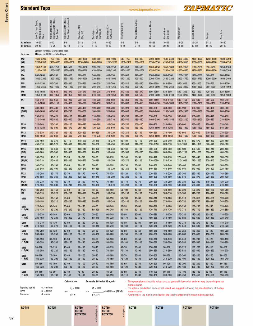
52
Sp
eed
Ch
art
www.tapmatic.comStandard Taps
Low
Car
bon
Stee
l, M
ediu
m C
arbo
n
Stee
l
Hig
h Ca
rbon
Ste
el,
Hig
h St
reng
th S
teel
, To
ol S
teel
Hig
h St
reng
th S
teel
, To
ol S
teel
Har
dene
d
Stai
nles
s 30
3,
304,
316
Stai
nles
s 41
0, 4
30, 1
7-4
Har
dene
d
Stai
nles
s 17
-4
Ann
eale
d
Tita
nium
Allo
ys
Nic
kel B
ase
Allo
ys
Alu
min
ium
Allo
ys
Alu
min
ium
Die
Cas
t
Mag
nesi
um
Bra
ss, B
ronz
e
Copp
er
Cast
Iron
A) m/minB) m/min
10–2020–40
8–1215–25
4–612–18
6–128–15
3–54–10
6–128–20
4–88–15
3–55–10
15–2540–60
10–1530–40
15–2540–60
15–2540–60
8–1215–25
10–2020–30
Tap sizeA) rpm for HSS-E uncoated taps B) rpm for HSS-E coated taps
M2(#2)
1600–32003200–6350
1250–19002400–4000
640–8001900–2850
800–19001250–2400
480–800640–1600
800–19001250–3200
640–12501250–2400
480–800800–1600
2400–40006350–9550
1600–24004750–6350
2400–40006350–9550
2400–40006350–9550
1250–19002400–4000
1600–32003200–4750
M3(#5)
1050–21002100–4250
850–12501600–2650
420–5301250–1900
530–1250850–1600
320–530420–1050
530–1250850–2100
420–850850–1600
320–530530–1050
1600–26504250–6350
1050–16003200–4250
1600–26504250–6350
1600–26504250–6350
850–12501600–2650
1050–21002100–3200
M4(#8)
800–16001600–3200
640–9501200–2000
320–400950–1450
400–950640–1200
240–400320–800
400–950640–1600
320–640640–1200
240–400400–800
1200–20003200–4750
800–12002400–3200
1200–20003200–4750
1200–20003200–4750
640–9501200–2000
800–16001600–2400
M5(#10)
640–12501250–2550
510–760950–1600
250–320760–1150
320–760510–950
190–320250–640
320–760510–1250
250–510510–950
190–320320–640
950–16002550–3800
640–9501900–2550
950–16002550–3800
950–16002550–3800
510–760950–1600
640–12501250–1900
M6(1/4)
530–10501050–2100
420–640800–1350
210–270640–950
270–640420–800
160–270210–530
270–640420–1050
210–420420–800
160–270270–530
800–13502100–3200
530–8001600–2100
800–13502100–3200
800–13502100–3200
420–640800–1350
530–10501050–1600
M7 450–910910–1800
360–550680–1150
180–230550–820
230–550360–680
140–230180–450
230–550360–910
180–360360–680
140–230230–450
680–11501800–2750
450–11501350–1800
680–11501800–2750
680–6801800–2750
360–550680–1150
450–910910–1350
M8(5/16)
400–800800–1600
320–480600–990
160–200480–720
200–480320–600
120–200160–400
200–480320–800
160–320320–600
120–200200–400
600–9901600–2400
400–6001200–1600
600–9901600–2400
600–9901600–2400
320–480600–990
400–800800–1200
M9 350–710710–1400
280–420530–880
140–180420–640
180–420280–530
110–180140–350
180–420280–710
140–280280–530
110–180180–350
530–8801400–2100
350–5301050–1400
530–8801400–2100
530–8801400–2100
280–420530–880
350–710710–1050
M10(3/8)
320–640640–1250
250–380480–800
130–160380–570
160–380250–480
100–160130–320
160–380250–640
130–250250–480
100–160160–320
480–8001250–1900
320–480950–1250
480–8001250–1900
480–8001250–1900
250–380480–800
320–640640–950
M12(1/2)
270–530530–1050
210–320400–660
110–130320–480
130–320210–400
80–130110–270
130–320210–530
110–210210–400
80–130130–270
400–6601050–1600
270–400800–1050
400–6601050–1600
400–6601050–1600
210–320400–660
270–530530–800
M14(9/16)
230–450450–910
180–270340–570
90–110270–410
110–270180–340
70–11090–230
110–270180–450
90–180180–340
70–110110–230
340–570910–1350
230–340680–910
340–570910–1350
340–570910–1350
180–270340–570
230–450450–680
M16(5/8)
200–400400–800
160–240300–500
80–100240–360
100–240160–300
60–10080–200
100–240160–400
80–160160–300
60–100100–200
300–500800–1200
200–300600–800
300–500800–1200
300–500800–1200
160–240300–500
200–400400–600
M18(11/16)
180–350350–710
140–210270–440
70–90210–320
90–210140–270
50–9070–180
90–210140–350
70–140140–270
50–9090–180
270–440710–1050
180–270530–710
270–440710–1050
270–440710–1050
140–210270–440
180–350350–530
M20(3/4)
160–320320–640
130–190240–400
60–80190–290
80–190130–240
50–8060–160
80–190130–320
60–130130–240
50–8080–160
240–400640–950
160–240480–640
240–400640–950
240–400640–950
130–190240–400
160–320320–480
M22(7/8)
140–290290–580
120–170220–360
60–70170–260
70–170120–220
40–7060–140
70–170120–290
60–120120–220
40–7070–140
220–360580–870
140–220430–580
220–360580–870
220–360580–870
120–170220–360
140–290290–430
M24(15/16)
130–270270–530
110–160200–330
50–70160–240
70–160110–200
40–7050–130
70–160110–270
50–110110–200
40–7070–130
200–330530–800
130–200400–530
200–330530–800
200–330530–800
110–160200–330
130–270270–400
M25(1)
130–250250–510
100–150190–320
50–60150–230
60–150100–190
40–6050–130
60–150100–250
50–100100–190
40–6060–130
190–320510–760
130–190380–510
190–320510–760
190–320510–760
100–150190–320
130–250250–380
M26 120–240240–490
100–150180–310
50–60150–220
60–150100–180
40–6050–120
60–150100–240
50–100100–180
40–6060–120
180–310490–730
120–180370–490
180–310490–730
180–310490–730
100–150180–310
120–240240–370
M27(1 1/16)
120–240240–470
90–140180–290
50–60140–210
60–14090–180
40–6050–120
60–14090–240
50–9090–180
40–6060–120
180–290470–710
120–180350–470
180–290470–710
180–290470–710
90–140180–290
120–240240–350
M28(1 1/8)
110–230230–450
90–140170–280
50–60140–200
60–14090–170
30–6050–110
60–14090–230
50–9090–170
30–6060–110
170–280450–680
110–170340–450
170–280450–680
170–280450–680
90–140170–280
110–230230–340
M30(1 3/16)
110–210210–420
80–130160–270
40–50130–190
50–13080–160
30–5040–110
50–13080–210
40–8080–160
30–5050–110
160–270420–640
110–160320–420
160–270420–640
160–270420–640
80–130160–270
110–210210–320
M32(1 1/4)
100–200200–400
80–120150–250
40–50120–180
50–12080–150
30–5040–100
50–12080–200
40–8080–150
30–5050–100
150–250400–600
100–150300–400
150–250400–600
150–250400–600
80–120150–250
100–200200–300
M33(1 5/16)
100–190190–390
80–120140–240
40–50120–170
50–12080–140
30–5040–100
50–12080–190
40–8080–140
30–5050–100
140–240390–580
100–140290–390
140–240390–580
140–240390–580
80–120140–240
100–190190–290
M36(1 7/16)
90–180180–350
70–110130–220
40–40110–160
40–11070–130
30–4040–90
40–11070–180
40–7070–130
30–4040–90
130–220350–530
90–130270–350
130–220350–530
130 -220350–530
70–110130–220
90–180180–270
M39(1 5/8)
80–160160–330
70–100120–200
30–40100–150
40–10070–120
20–4030–80
40–10070–160
30–7070–120
20–4040–80
120–200330–490
80–120240–330
120–200330–490
120–200330–490
70–100120–200
80–160160–240
M40 80–160160–320
60–100120–200
30–40100–140
40–10060–120
20–4030–80
40–10060–160
30–6060–120
20–4040–80
120–200320–480
80–120240–320
120–200320–480
120–200320–480
60–100120–200
80–160160–240
M42(1 3/4)
80–150150–300
60–90110–190
30–4090–140
40–9060–110
20–4030–80
40–9060–150
30–6060–110
20–4040–80
110–190300–450
80–110230–300
110–190300–450
110–190300–450
60–90110–190
80–150150–230
RDT15 RDT25 RDT50RCT50RCTXT50
RDT50RCT50RCTXT50
RCT85 RCT85 RCT100 RCT150
- The speed given are guide values acc. to general information and can vary depending on tap manufacturer.- For optimal production and correct speed, we suggest following the specifications of the tap
manufacturer.- Furthermore, the maximum speed of the tapping attachment must not be exceeded.
sint
ered
gea
rs
cut g
ears
Tapping speed vc = m/minRPM n = U/minDiameter d = mm
Calculation:
vc × 1000n = d × π
Example: M8 with 25 m/min
25 × 1000n = = 995 U/min (RPM) 8 × 3.14

53
Sp
eed
Ch
art
www.tapmatic.comHigh Speed/Top Speed Taps
Low
Car
bon
Stee
l, M
ediu
m C
arbo
n
Stee
l
Hig
h Ca
rbon
Ste
el,
Hig
h St
reng
th S
teel
, To
ol S
teel
Hig
h St
reng
th S
teel
, To
ol S
teel
Har
dene
d
Stai
nles
s 30
3,
304,
316
Stai
nles
s 41
0, 4
30, 1
7-4
Har
dene
d
Stai
nles
s 17
-4
Ann
eale
d
Tita
nium
Allo
ys
Nic
kel B
ase
Allo
ys
Alu
min
ium
Allo
ys
Alu
min
ium
Die
Cas
t
Mag
nesi
um
Bra
ss, B
ronz
e
Copp
er
Cast
Iron
A) m/minB) m/min
50–70—
20–3040–60
15–2030–50
10–15—
6–10—
10–15—
12–15—
6–12—
50–7060–80
40–5050–70
50–7040–80
30–7060–80
20–3030–50
25–4030–50
Tap sizeA) rpm for HSS-E uncoated tapsB) rpm for HSS-E coated taps
M2(#2)
7950–11150640–800
3200–47506350–9550
2400–32004750–7950
1600–2400640–800
800–1600640–800
1600–2400640–800
1900–2400–
800–1900–
7950–111509550–12750
6350–79507950–11150
7950–111506350–12750
4750–111509550–12750
3200–47504750–7950
4000–63504750–7950
M3(#5)
5300–7450420–530
2100–32004250–6350
1600–21003200–5300
1050–1600420–530
530–1050420–530
1050–1600420–530
1250–1600–
530–1250–
5300–74506350–8500
4250–53005300–7450
5300–74504250–8500
3200–74506350–8500
2100–32003200–5300
2650–42503200–5300
M4(#8)
4000–5550320–600
1600–24003200–4750
1200–16002400–4000
800–1200320–400
400–800320–400
800–1200320–400
950–1200–
400–950–
4000–55504750–6350
3200–40004000–5550
4000–55503200–6350
2400–55504750–6350
1600–24002400–4000
2000–32002400–4000
M5(#10)
3200–4450250–320
1250–19002550–3800
950–12501900–3200
640–950250–320
320–640250–320
640–950250–320
760–950–
320–760–
3200–44503800–5100
2550–32003200–4450
3200–44502550–5100
1900–44503800–5100
1250–19001900–3200
1600–25501900–3200
M6(1/4)
2650–3700210–270
1050–16002100–3200
800–10501600–2650
530–800210–270
270–530210–270
530–800210–270
640–800–
270–640–
2650–37003200–4250
2100–26502650–3700
2650–37002100–4250
1600–37003200–4250
1050–16001600–2650
1350–21001600–2650
M7 2250–3200180–230
910–13501800–2750
680–9101350–2250
450–680180–230
230–450180–230
450–680180–230
550–680–
230–550–
2250–32002750–3650
1800–22502250–3200
2250–32001800–3650
1350–32002750–3650
910–13501350–2250
1150–18001350–2250
M8(5/16)
2000–2800160–200
800–12001600–2400
600–8001200–2000
400–600160–200
200–400160–200
400–600160–200
480–600–
200–480–
2000–28002400–3200
1600–20002000–2800
2000–28001600–3200
1200–28002400–3200
800–12001200–2000
990–16001200–2000
M9 1750–2500140–180
710–10501400–2100
530–7101050–1750
350–530140–180
180–350140–180
350–530140–180
420–530–
180–420–
1750–25002100–2850
1400–17501750–2500
1750–25001400–2850
1050–25002100–2850
710–10501050–1750
880–14001050–1750
M10(3/8)
1600–2250130–160
640–9501250–1900
480–640950–1600
320–480130–160
160–320130–160
320–480130–160
380–480–
160–380–
1600–22501900–2550
1250–16001600–2250
1600–22501250–2550
950–22501900–2550
640–950950–1600
800–1250950–1600
M12(1/2)
1350–1850110–130
530–8001050–1600
400–530800–1350
270–400110–130
130–270110–130
270–400110–130
320–400–
130–320–
1350–18501600–2100
1050–13501350–1850
1350–18501050–2100
800–18501600–2100
530–800800–1350
660–1050800–1350
M14(9/16)
1150–160090–110
450–680910–1350
340–450680–1150
230–34090–110
110–23090–110
230–34090–110
270–340–
110–270–
1150–16001350–1800
910–11501150–1600
1150–1600910–1800
680–16001350–1800
450–680680–1150
570–910680–1150
M16(5/8)
990–140080–100
400–600800–1200
300–400600–990
200–30080–100
100–20080–100
200–30080–100
240–300–
100–240–
990–14001200–1600
800–990990–1400
990–1400800–1600
600–14001200–1600
400–600600–990
500–800600–990
M18(11/16)
880–125070–90
350–530710–1050
270–350530–880
180–27070–90
90–18070–90
180–27070–90
210–270–
90–210–
880–12501050–1400
710–880880–1250
880–1250710–1400
530–12501050–1400
350–530530–880
440–710530–880
M20(3/4)
800–110060–80
320–480640–950
240–320480–800
160–24060–80
80–16060–80
160–24060–80
190–240–
80–190–
800–1100950–1250
640–800800–1100
800–1100640–1250
480–1100950–1250
320–480480–800
400–640480–800
M22(7/8)
720–100060–70
290–430580–870
220–290430–720
140–22060–70
70–14060–70
140–22060–70
170–220–
70–170–
720–1000870–1150
580–720720–1000
720–1000580–1150
430–1000870–1150
290–430430–720
360–580430–720
M24(15/16)
660–93050–70
270–400530–800
200–270400–660
130–20050–70
70–13050–70
130–20050–70
160–200–
70–160–
660–930800–1050
530–660660–930
660–930530–1050
400–930800–1050
270–400400–660
330–530400–660
M25(1)
640–89050–60
250–380510–760
190–250380–640
130–19050–60
60–13050–60
130–19050–60
150–190–
60–150–
640–890760–1000
510–640640–890
640–890510–1000
380–890760–1000
250–380380–640
320–510380–640
M26 610–86050–60
240–370490–730
180–240370–610
120–18050–60
60–12050–60
120–18050–60
150–180–
60–150–
610–860730–980
490–610610–860
610–860490–980
370–860730–980
240–370370–610
310–490370–610
M27(1 1/16)
590–83050–60
240–350470–710
180–240350–590
120–18050–60
60–12050–60
120–18050–60
140–180–
60–140–
590–830710–940
470–590590–830
590–830470–940
350–830710–940
240–350350–590
290–470350–590
M28(1 1/8)
570–80050–60
230–340450–680
170–230340 –570
110–17050–60
60–11050–60
110–17050–60
140–170–
60–140–
570–800680–910
450–570570–800
570–800450–910
340–800680–910
230–340340–570
280–450340–570
M30(1 3/16)
530–74040–50
210–320420–640
160–210320–530
110–16040–50
50–11040–50
110–16040–50
130–160–
50–130–
530–740640–850
420–530530–740
530–740420–850
320–740640–850
210–320320–530
270–420320–530
M32(1 1/4)
500–70040–50
200–300400–600
150–200300–500
100–15040–50
50–10040–50
100–15040–50
120–150–
50–120–
500–700600–800
400–500500–700
500–700400–800
300–700600–800
200–300300–500
250–400300–500
M33(1 5/16)
480–68040–50
190–290390–580
140–190290–480
100–14040–50
50–10040–50
100–14040–50
120–140–
50–120–
480–680580–770
390–480480–680
480–680390–770
290–680580–770
190–290290–480
240–390290–480
M36(1 7/16)
440–62040–40
180–270350–530
130–180270–440
90–13040–40
40–9040–40
90–13040–40
110–130–
40–110–
440–620530–710
350–440440–620
440–620350–710
270–620530–710
180–270270–440
220–350270–440
M39(1 5/8)
410–57030–40
160–240330–490
120–160240–410
80–12030–40
40–8030–40
80–12030–40
100–120–
40–100–
410–570490–650
330–410410–570
410–570330–650
240–570490–650
160–240240–410
200–330240–410
M40 400–56030–40
160–240320–480
120–160240–400
80–12030–40
40–8030–40
80–12030–40
100–120–
40–100–
400–560480–640
320–400400–560
400–560320–640
240–560480–640
160–240240–400
200–320240–400
M42(1 3/4)
380–53030–40
150–230300–450
110–150230–380
80–11030–40
40–8030–40
80–11030–40
90–110–
40–90–
380–530450–610
300–380380–530
380–530300–610
230–530450–610
150–230230–380
190–300230–380
RDT15 RDT25 RDT50RCT50RCTXT50
RDT50RCT50RCTXT50
RCT85 RCT85 RCT100 RCT150
sint
ered
gea
rs
cut g
ears
- The speed given are guide values acc. to general information and can vary depending on tap manufacturer.- For optimal production and correct speed, we suggest following the specifications of the tap
manufacturer.- Furthermore, the maximum speed of the tapping attachment must not be exceeded.
Calculation:
vc × 1000n = d × π
Example: M8 with 40 m/min
40 × 1000n = = 1592 U/min (RPM) 8 × 3.14
Tapping speed vc = m/minRPM n = U/minDiameter d = mm
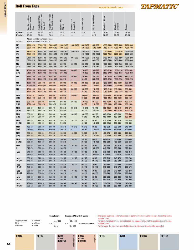
54
Sp
eed
Ch
art
www.tapmatic.comRoll From Taps
Low
Car
bon
Stee
l,M
ediu
m C
arbo
n St
eel
Hig
h Ca
rbon
Ste
el,
Hig
h St
reng
th S
teel
, To
ol S
teel
Hig
h St
reng
th S
teel
, To
ol S
teel
Har
dene
d
Stai
nles
s 30
3,
304,
316
Stai
nles
s 17
-4
Ann
eale
d
Tita
nium
Allo
ys
Nic
kel B
ase
Allo
ys
Alu
min
ium
Allo
ys
Alu
min
ium
Die
Cas
t
Copp
er
A) m/minB) m/min
30–4040–60
20–3030–50
15–2525–40
10–1512–20
10–15—
5–15—
3–58–12
30–6050–70
20–4030–50
15–2525–50
Tap sizeA) rpm for HSS-E uncoated tapsB) rpm for HSS-E coated taps
M2(#2)
4750–63506350–9550
3200–47504750–7950
2400–40004000–6350
1600–24001900–3200
1600–2400–
800–2400320–1600
480–8001250–1900
4750–95507950–11150
3200–63504750–7950
2400–40004000–7950
M3(#5)
3200–42504250–6350
2100–32003200–5300
1600–26502650–4250
1050–16001250–2100
1050–1600–
530–1600210–1050
320–530850–1250
3200–63505300–7450
2100–42503200–5300
1600–26502650–5300
M4(#8)
2400–32003200–4750
1600–24002400–4000
1200–20002000–3200
800–1200950–1600
800–1200–
400–1200160–800
240–400640–950
2400–47504000–5550
1600–32002400–4000
1200–20002000–4000
M5(#10)
1900–25502550–3800
1250–19001900–3200
950–16001600–2550
640–950760–1250
640–950–
320–950130–640
190–320510–760
1900–38003200–4450
1250–25501900–3200
950–16001600–3200
M6(1/4)
1600–21002100–3200
1050–16001600–2650
800–13501350–2100
530–800640–1050
530–800–
270–800110–530
160–270420–640
1600–32002650–3700
1050–21001600–2650
800–13501350–2650
M7 1350–18001800–2750
910–13501350–2250
680–11501150–1800
450–680550–910
450–680–
230–68090–450
140–230360–550
1350–27502250–3200
910–18001350–2250
650–11501150–2250
M8(5/16)
1200–16001600–2400
800–12001200–2000
600–990990–1600
400–600480–800
400–600–
200–60080–400
120–200320–480
1200–24002000–2800
800–16001200–2000
600–990990–2000
M9 1050–14001400–2100
710–10501050–1750
530–880880–1400
350–530420–710
350–530–
180–53070–350
110–180280–420
1050–21001750–2500
710–14001050–1750
530–880880–1750
M10(3/8)
950–12501250–1900
640–950950–1600
480–800800–1250
320–480380–640
320–480–
160–48060–320
100–160250–380
950–19001600–2250
640–1250950–1600
480–800800–1600
M12(1/2)
800–10501050–1600
530–800800–1350
400–660660–1050
270–400320–530
270–400–
130–40050–270
80–130210–320
800–16001350–1850
530–1050800–1350
400–660660–1350
M14(9/16)
680–910910–1350
450–680680–1150
340–570570–910
230–340270–450
230–340–
110–34050–230
70–110180–270
680–13501150–1600
450–910680–1150
340–570570–1150
M16(5/8)
600–800800–1200
400–600600–990
300–500500–800
200–300240–400
200–300–
100–30040–200
60–100160–240
600–1200990–1400
400–800600–990
300–500500–990
M18(11/16)
530–710710–1050
350–530530–880
270–440440–710
180–270210–350
180–270–
90–27040–180
50–90140–210
530–1050880–1250
350–710530–880
270–440440–880
M20(3/4)
480–640640–950
320–480480–800
240–400400–640
160–240190–320
160–240–
80–24030–160
50–80130–190
480–950800–1100
320–640480–800
240–400400–800
M22(7/8)
430–580580–870
290–430430–720
220–360360–580
140–220170–290
140–220–
70–22030–140
40–70120–170
430–870720–1000
290–580430–720
220–360360–720
M24(15/16)
400–530530–800
270–400400–660
200–330330–530
130–200160–270
130–200–
70–20030–130
40–70110–160
400–800660–930
270–530400–660
200–330330–660
M25(1)
380–510510–760
250–380380–640
190–320320–510
130–190150–250
130–190–
60–19030–130
40–60100–150
380–760640–890
250–510380–640
190–320320–640
M26 370–490490–730
240–370370–610
180–310310–490
120–180150–240
120–180–
60–18020–120
40–60100–150
370–730610–860
240–490370–610
180–310310–610
M27(1 1/16)
350–470470–710
240–350350–590
180–290290–470
120–180140–240
120–180–
60–18020–120
40–6090–140
350–710590–830
240–470350–590
180–290290–590
M28(1 1/8)
340–450450–680
230–340340–570
170–280280–450
110–170140–230
110–170–
60–17020–110
30–6090–140
340–680570–800
230–450340–570
170–280280–570
M30(1 3/16)
320–420420–640
210–320320–530
160–270270–420
110–160130–210
110–160–
50–16020–110
30–5080–130
320–640530–740
210–420320–530
160–270270–530
M32(1 1/4)
300–400400–600
200–300300–500
150–250250–400
100–150120–200
100–150–
50–15020–100
30–5080–120
300–600500–700
200–400300–500
150–250250–500
M33(1 5/16)
290–390390–580
190–290290–480
140–240240–390
100–140120–190
100–140–
50–14020–100
30–5080–120
290–580480–680
190–390290–480
140–240240–480
RDT15 RDT25 RDT50RCT50RCTXT50
RDT50RCT50RCTXT50
RCT85 RCT85 RCT100 RCT150
sint
ered
gea
rs
cut g
ears
- The speed given are guide values acc. to general information and can vary depending on tap manufacturer.- For optimal production and correct speed, we suggest following the specifications of the tap
manufacturer.- Furthermore, the maximum speed of the tapping attachment must not be exceeded.
Calculation:
vc × 1000n = d × π
Example: M8 with 30 m/min
30 × 1000n = = 1194 U/min (RPM) 8 × 3.14
Tapping speed vc = m/minRPM n = U/minDiameter d = mm

55
Inst
alla
tio
n
www.tapmatic.comInstallation of Tapping Attachments
Preferred Installation Alternative installation
Order code.36007 Standard Block
Order code36010 Standard Block
Stop arm plate
Order code Bolt size Order code Bolt size
69383A M6 69389A 5/16"-1869384A M8 69390A 5/16"-2469385A M10 69391A 3/8"-1669386A M12 69392A 3/8"-2469387A 1/4"-20 69393A 1/2"-1369388A 1/4"-28 69394A 1/2"-20
Order code Center Distance
723420 53-69723421 68-77723422 74-88723423 86-100
Order code For Model392552 RDT15, RDT25395052 RDT50
Stop arm plate housing assembly
Torque bar holder assembliesFor the use with straight stop arm. Torque bar installation must be stronger than the largest tap.
Tapmatic can supply a tapping attachment ready to fit your machining centerRDT and RCT tapping attachments eliminate the need for the machine spindle to reverse by automatically reversing the taps rotation when the machine retracts. For the automatic reversal to function a stop arm is needed to prevent the housing of the tapping attachment from rotating. Our stop arm locking mechanism allows the tool to easily make automatic tool changes.
Tapmatic maintains a large data base of machining center installations Please simply let us know the machine manufacturer, make and model and we may already have the installation information available to provide a tool ready to run on your machine.
My machine already has a stop blockIf your machine already has an anti-rotation stop block installed, please let us know the dimensions shown in the drawing below. We can prepare a tool to go with your existing stop block.
My machine does not have a stop block If your machine does not have a stop block already installed, we would be pleased to prepare one for you. Please simply fill in the form on the back cover or download it from our homepage and forward us the information. We will be pleased to submit an offer to you.
Standard stop blocks are available if you would like to design your own installation. These blank stop blocks can be modified to fit the bolt pattern of your machine.
Gage Line to Mounting Surface G = Center Distance (commonly 55, 65, or 80) Z = Diameter of Bore or Width of Slot in Stop Block D = Depth of Bore or Slot in Stop Block E = Total Height of Stop Block F = Machine Spindle Taper (SK, BT, CAT, HSK… ) Shank = Machine Manufacturer and Model =
G
Z
F
E D
G
Z
F
E D
DISTANCECENTER
SIZETHREAD
55
STOP ARMPLATEHOUSING ASSEMBLY
STOP ARMPLATE
TORQUE BARHOLDERASSEMBLY
32
92
20
11.4
32 18.3 139
50
20
11.4
32 18.3
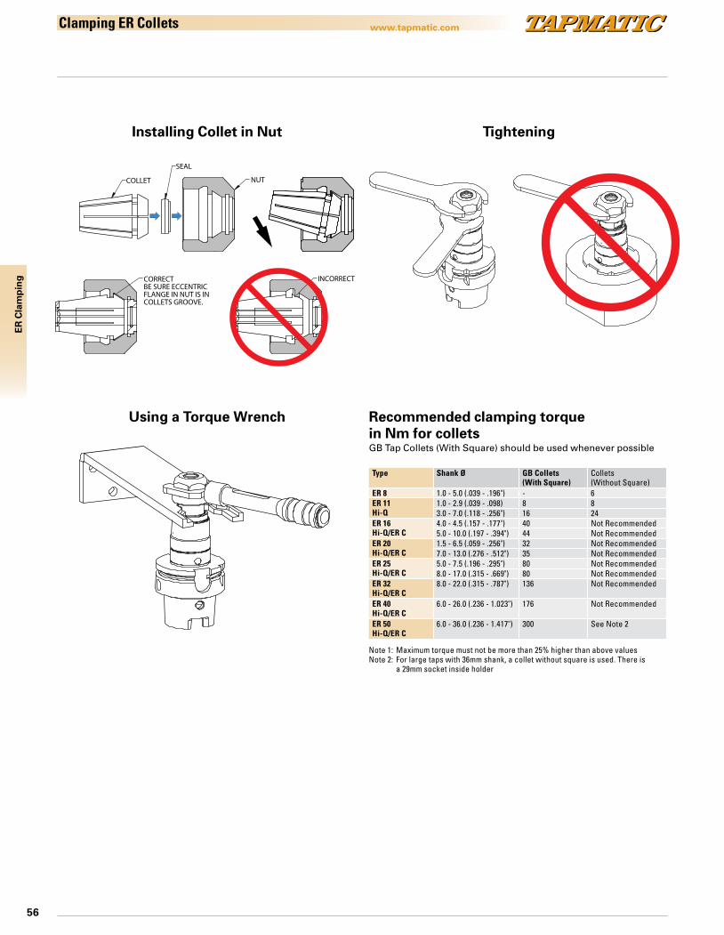
56
ER
Cla
mp
ing
www.tapmatic.com
NUT
SEAL
COLLET
CORRECTBE SURE ECCENTRICFLANGE IN NUT IS INCOLLETS GROOVE.
INCORRECT
Clamping ER Collets
Installing Collet in Nut
Type Shank Ø GB Collets(With Square)
Collets(Without Square)
ER 8 1.0 - 5.0 (.039 - .196") - 6ER 11Hi-Q
1.0 - 2.9 (.039 - .098) 8 83.0 - 7.0 (.118 - .256") 16 24
ER 16Hi-Q/ER C
4.0 - 4.5 (.157 - .177") 40 Not Recommended5.0 - 10.0 (.197 - .394") 44 Not Recommended
ER 20Hi-Q/ER C
1.5 - 6.5 (.059 - .256") 32 Not Recommended7.0 - 13.0 (.276 - .512") 35 Not Recommended
ER 25Hi-Q/ER C
5.0 - 7.5 (.196 - .295") 80 Not Recommended8.0 - 17.0 (.315 - .669") 80 Not Recommended
ER 32Hi-Q/ER C
8.0 - 22.0 (.315 - .787") 136 Not Recommended
ER 40Hi-Q/ER C
6.0 - 26.0 (.236 - 1.023") 176 Not Recommended
ER 50Hi-Q/ER C
6.0 - 36.0 (.236 - 1.417") 300 See Note 2
Note 1: Maximum torque must not be more than 25% higher than above valuesNote 2: For large taps with 36mm shank, a collet without square is used. There is a 29mm socket inside holder
REV. DESCRIPTION DATE BY:REVISIONS
5 4 3 2 1
1
DRAWN BY:
DATENAME
DESCRIPTIONPOST FALLS, IDAHO
TAPMATIC CORPORATION
DO NOT SCALE DRAWING
4150h6320 with TORQUE wrenchSHEET 1 OF 1
UNLESS OTHERWISE SPECIFIED:
SCALE: 1:2 WEIGHT: #
REVDWG. NO.
ASIZE
FINISH:
MATERIAL:
TOLERANCES:ANGULAR 1/2 DegFRACTIONAL .015TWO PLACE DECIMAL .010THREE PLACE DECIMAL .005
THIS PRINT IS THE PROPERTY OF TAPMATIC CORPORATION. ALL INFORMATIONAND DATA ON THE PRINT ARE PROPRIETARY TO TAPMATIC CORPORATION.
SURFACE FINSISH:
REMOVE BURRS AND SHARP EDGES .005 TO .020
OPERATION:
REV. DESCRIPTION DATE BY:REVISIONS
5 4 3 2 1
1
DRAWN BY:
DATENAME
mj
DESCRIPTIONPOST FALLS, IDAHO
TAPMATIC CORPORATION
DO NOT SCALE DRAWING
4150h6320 wrenches corr and incorr
SHEET 1 OF 1
UNLESS OTHERWISE SPECIFIED:
SCALE: 1:2 WEIGHT: #
REVDWG. NO.
ASIZE
FINISH:
MATERIAL:
TOLERANCES:ANGULAR 1/2 DegFRACTIONAL .015TWO PLACE DECIMAL .010THREE PLACE DECIMAL .005
SFT50 with wrenchescorrectyl and incorrectly
THIS PRINT IS THE PROPERTY OF TAPMATIC CORPORATION. ALL INFORMATIONAND DATA ON THE PRINT ARE PROPRIETARY TO TAPMATIC CORPORATION.
SURFACE FINSISH:
5-11-16
REMOVE BURRS AND SHARP EDGES .005 TO .020
OPERATION:
Tightening
Recommended clamping torque in Nm for colletsGB Tap Collets (With Square) should be used whenever possible
Using a Torque Wrench

57
Saf
ety,
War
ran
ty
www.tapmatic.comSafety
To Avoid Serious Injury And Ensure Best Results For Your Tapping Operation, Please Read Carefully All Operator And Safety Instructions Provided For This Tapping Unit as well as all other safety instructions that are applicable, especially those for your machine tool.
n 1. Proper clothing: The rotating spindle of a machine tool can snag loose fitting clothing, jewelry or long hair. Never wear jewelry, long sleeves, neckties, gloves or anything else that could become caught when operating a machine tool. Long hair must be restrained or netted to prevent it from becoming entangled in rotating spindle.
n 2. Proper eye protection: Always wear safety glasses with side shields to protect your eyes from flying particles.
n 3. Proper work piece fixation: Never hold the work piece or the vise it is held in, by hand. Never fasten it with wire or anything similar! The work piece must be clamped firmly to the table of the machine so that it cannot move, rotate or lift.
n 4. On machining centers: The same rule for stop arm and stop block installation applies «Always be sure that the installation is stronger than the largest tap.» Automatic tool changes should only be made on enclosed machines.
n 5. The tapping attachment housing, drive spindle and tap itself can become hot to the touch after operation. Use caution when removing the attachment from the machine or handling.
n 6. Always be aware of the potential hazards of a machining operation: Sometimes working with your machine can seem routine. You may find that you are no longer concentrating on the operation. A feeling of false security can lead to serious injury. Always be alert to the dangers of the machines with which you work. Always keep hands, body parts, clothing, jewelry and hair out of the areas of operation, when the machine spindle is rotating. Areas of operation include the immediate point of machining and all transmission components including the tapping attachment. Never bring your hand, other body parts or anything attached to your body into any of these areas until the machine spindle is completely stopped.
n 7. Be aware of any other applicable safety instructions/requirements.
Check List for good tapping1. Never use this unit before reading all safety instructions for this
attachment as well as the machine it is to be used on.2. Is tap sharp and of correct design for current job?3. Is tap in proper alignment with drilled hole?4. Is machine speed correct?5. Is machine feed correct?6. Is machine stop set properly so tap releases in neutral rather
than bottoming in work piece or fixture?7. Is drilled hole the correct size?8. Is clearance between the drilled hole and tap sufficient at start
position to allow the tap to clear the hole upon retraction?9. Is the stop arm of the tapping attachment held rigidly against
rotation. Stop Arm installation must be stronger than largest tap.
10. Is the proper cutting fluid or coolant being used for lubricating the tap?
11. If a bottom hole is being tapped is there sufficient chip clearance?
12. Is the correct Tapmatic model for the specific job requirement being used? (Capacity should be reduced by 25 % for roll form taps.)
WARNING
Warranty Policy
Tapmatic Corporation warrants to original equipment manufacturers, distributors and industrial users of its products, that each new product manufactured or supplied by Tapmatic Corporation shall be free from defects in material and workmanship. Tapmatic Corporation’s obligation under this warranty is limited to repairing any product which shall, within one year from the date of sale, be returned freight prepaid to Tapmatic Corporation, Post Falls, Idaho. Any product returned for inspection for warranty repair consideration must be returned complete with chuck nut, back jaw and if the tool is a reversing unit, stop arm, as well as, complete information as to operating conditions, machine set up and application of cutting fluid. The provision of this warranty shall not apply to any parts of a Tapmatic product subject to conditions, machine setup or application of cutting fluid or which has been repaired or altered if such repair or alteration, which in the judgement of Tapmatic Corporation, would adversely affect the performance of the product. This warranty is in lieu of all other warranties, express or implied, including any implied warranty of merchantability or fitness for particular purpose. Tapmatic Corporation shall have no liability or responsibility on any claim of any kind, whether in contract, tort, or otherwise, for any loss or damage arising out of, connected with, or resulting from the manufacture, sale, delivery or use of any products sold hereunder in excess of the cost of repair as provided herein. In no event shall Tapmatic Corporation be liable for any special, incedental, or consequential damages. Tapmatic Corporation makes no other warranties, express or implied, except as set forth above and Tapmatic Corporation neither assumes nor authorizes any other person or entity to assume for it any other obligation or liability in connection with any of its products.
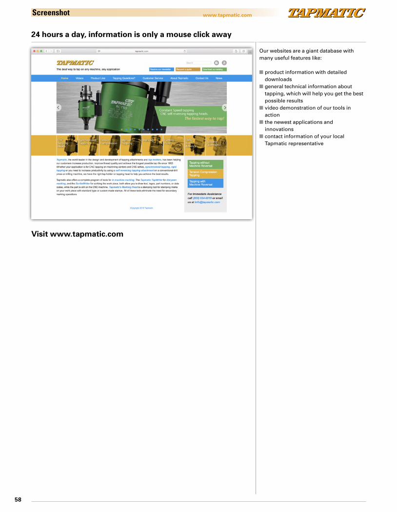
58
www.tapmatic.comScreenshot
Our websites are a giant database with many useful features like:
n product information with detailed downloadsn general technical information about tapping, which will help you get the best possible resultsn video demonstration of our tools in actionn the newest applications and
innovationsn contact information of your local Tapmatic representative
24 hours a day, information is only a mouse click away
Visit www.tapmatic.com
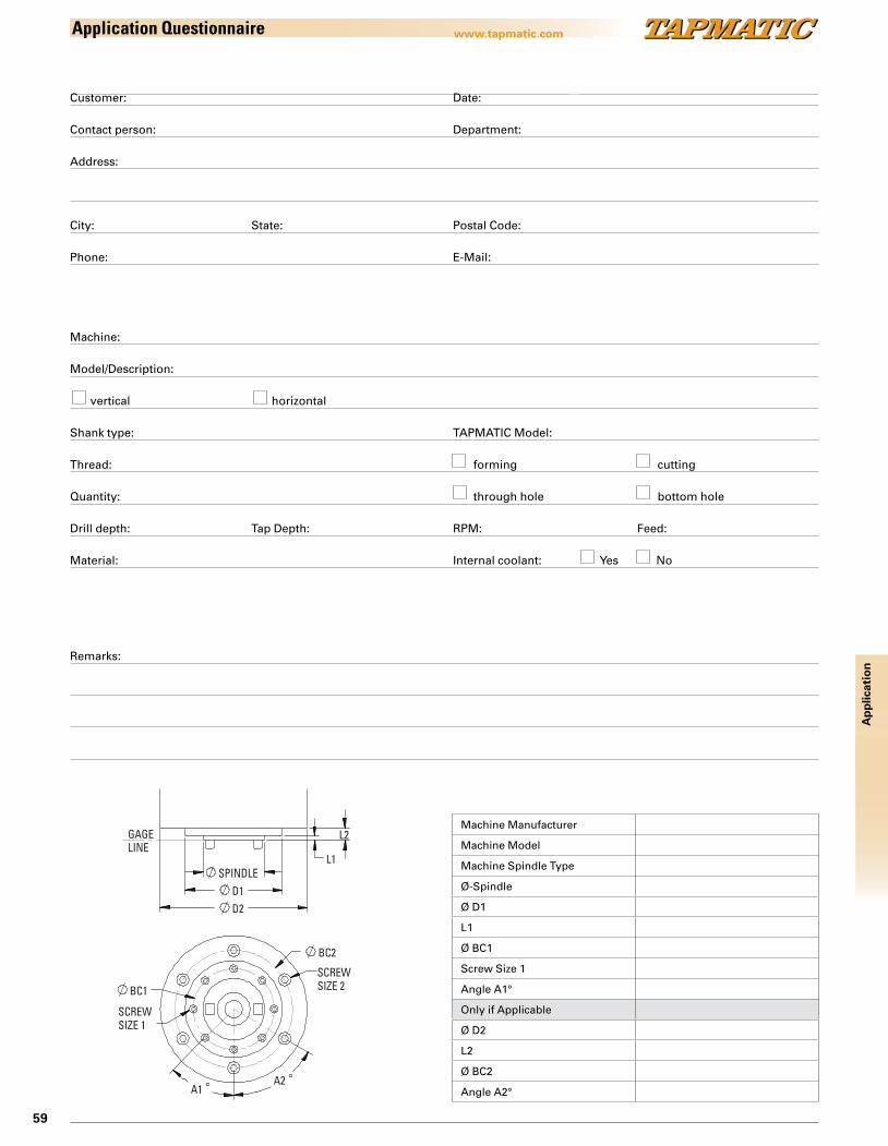
59
Ap
plic
atio
n
www.tapmatic.comApplication Questionnaire
Customer: Date: Contact person: Department: Address:
City: State: Postal Code: Phone: E-Mail: Machine: Model/Description: vertical horizontal Shank type: TAPMATIC Model: Thread: forming cutting Quantity: through hole bottom hole Drill depth: Tap Depth: RPM: Feed: Material: Internal coolant: Yes No
Remarks:
Machine Manufacturer
Machine Model
Machine Spindle Type
Ø-Spindle
Ø D1
L1
Ø BC1
Screw Size 1
Angle A1°
Only if Applicable
Ø D2
L2
Ø BC2
Angle A2°
BC2
BC1
A1A2
SCREW SIZE 2
SCREW SIZE 1
SPINDLED1D2
L1
L2GAGELINE
IX.2010/e Subject to technical changes (without notice).
www.tapmatic.com
Sold through:
Headquarters:
TAPMATIC Corporation802, Clearwater Loop, Post Falls, Idaho 83854, USAPhone 001-208-773 29 51, Fax 001-208-773 30 [email protected], www.tapmatic.com
TAPMATIC Post Falls, USA
European Service Center:
TAPMATIC UKMillers Close Industrial EstateFakenham Norfolk NR21 8NWPhone +44 1328 863676, Fax +44 1328 [email protected]
TAPMATIC is represented throughout the world.Please find your local dealer on:
www.tapmatic.com