DL05 and DL06 PLC Overview THE DL05 & DL06 FAMILY OF … · in V-memory in 16-bit registers....
48
The DL05 micro PLC family includes eight different models. Each has eight inputs and six outputs in the base unit. The DL05 has one option card slot, which can be used to expand the I/O count, provide additional communica- tions capability or add a real-time clock and battery back-up. The larger DL06 micro PLC family has 20 inputs and 16 outputs in the base unit. The DL06 has four option card slots which can be used to add I/O or provide additional communications options. Instruction sets The DL05 CPU offers PID capability, high-speed counting, and the same powerful instruction set as our popular DL250 CPU. All DL05 PLCs have two built-in RS-232C communications ports that can be used for programming, oper- ator interface, networking, etc. The DL06 CPU offers PID capability, floating point number handling, and an instruction set very similar to our new D2-260 CPU. Many powerful new instructions are included. All DL06 PLCs have two built-in communications ports that can be used for programming, operator interface, networking, etc. One of the DL06 ports is a multi-function port capable of RS232C, RS422, or RS485 communications. Power options The DL05 and DL06 families have AC and DC power options. They are also offered with a variety of I/O options. You can explore the Quick Selection Guide on the next page to choose the right PLC for your application. High-speed inputs and outputs Units with DC inputs have selectable high-speed input features on three input points (DL05) or four input points (DL06). Units with DC outputs can use the first two outputs as a single bi-direc- tional pulse output. Detailed specifica- tions for each model appear later in this section. DL05 and DL06 PLC Overview 1-800-633-0405 264 PLC and PC Products General Specifications AC Powered Power 110/220VAC (+ 10%, -15%), 50-60Hz Input Voltage Range 95-240VAC Maximum Power 30VA (DL05) 40VA (DL06) Maximum Inrush Current 13A, 1ms (240VAC) Storage Temperature -4ºF to 158ºF (-20ºC to 70ºC) Ambient Operating Temperature Ambient Humidity 5% - 95% relative humidity (non-condensing) Vibration Resistance MIL STD 810C, Method 514.2 Shock Resistance MIL STD 810C, Method 516.2 Noise Immunity NEMA (ICS3-304) Atmosphere No corrosive gases DC Powered 32°F to 131°F (0°C to 55°C) 12/24VDC 12-24VDC 20W 10A < 1ms THE DL05 & DL06 F AMILY OF PRODUCTS Communication ports Option cards Optional LCD display DL05 8 in/6 out DL06 20 in/16 out Communication ports
Transcript of DL05 and DL06 PLC Overview THE DL05 & DL06 FAMILY OF … · in V-memory in 16-bit registers....

The DL05 micro PLC family includeseight different models. Each has eightinputs and six outputs in the base unit.The DL05 has one option card slot,which can be used to expand the I/Ocount, provide additional communica-tions capability or add a real-time clockand battery back-up.
The larger DL06 micro PLC family has20 inputs and 16 outputs in the baseunit. The DL06 has four option cardslots which can be used to add I/O orprovide additional communicationsoptions.
Instruction setsThe DL05 CPU offers PID capability,high-speed counting, and the samepowerful instruction set as our popularDL250 CPU. All DL05 PLCs have twobuilt-in RS-232C communications portsthat can be used for programming, oper-ator interface, networking, etc.
The DL06 CPU offers PID capability,floating point number handling, and aninstruction set very similar to our newD2-260 CPU. Many powerful newinstructions are included. All DL06PLCs have two built-in communicationsports that can be used for programming,operator interface, networking, etc. Oneof the DL06 ports is a multi-functionport capable of RS232C, RS422, orRS485 communications.
Power optionsThe DL05 and DL06 families have ACand DC power options. They are alsooffered with a variety of I/O options. Youcan explore the Quick Selection Guideon the next page to choose the right PLCfor your application.
High-speed inputsand outputsUnits with DC inputs have selectablehigh-speed input features on three inputpoints (DL05) or four input points(DL06). Units with DC outputs can usethe first two outputs as a single bi-direc-tional pulse output. Detailed specifica-tions for each model appear later in thissection.
DL05 and DL06 PLC Overview1
-8
00
-6
33
-0
40
5
264 PLC and PC Products
General Specifications AC Powered
Power 110/220VAC (+ 10%, -15%),50-60Hz
Input Voltage Range 95-240VAC
Maximum Power 30VA (DL05) 40VA (DL06)
Maximum Inrush Current 13A, 1ms (240VAC)
Storage Temperature -4ºF to 158ºF (-20ºC to 70ºC)
Ambient Operating Temperature Ambient Humidity 5% - 95% relative humidity (non-condensing)
Vibration Resistance MIL STD 810C, Method 514.2
Shock Resistance MIL STD 810C, Method 516.2
Noise Immunity NEMA (ICS3-304)
Atmosphere No corrosive gases
DC Powered
32°F to 131°F (0°C to 55°C)
12/24VDC
12-24VDC
20W
10A < 1ms
THE DL05 & DL06 FAMILY OF PRODUCTS
Communication ports
Option cards
Optional LCD display
DL058 in/6 out
DL0620 in/16 out
Communication ports

D0-05AA8 AC inputs6 AC outputs, 0.5A/point
D0-05AD8 AC inputs6 DC outputs (sinking), 1.0A/point
Two outputs can be used as a single bi-directional 7kHz pulse output
D0-05AR8 AC inputs6 relay outputs, 2A/point
D0-05DA8 DC inputs
Three inputs are filtered inputs, can alsobe configured as a single 5kHz high-speedcounter, interrupt input, or pulse catchinput
6 AC outputs, 0.5A/point
D0-05DD8 DC inputs
Three inputs are filtered inputs, can alsobe configured as a single 5kHz high-speedcounter, interrupt input, or pulse catchinput
6 DC outputs (sinking), 1.0A/pointTwo outputs can be used as a single bi-directional 7kHz pulse output
265PLC and PC Products
DL05 and DL06 PLC Selection Guide PLC/PC
QUICK SELECTION GUIDE
D0-05DR8 DC inputs
Three inputs are filtered inputs, can alsobe configured as a single 5kHz high-speedcounter, interrupt input, or pulse catchinput
6 relay outputs, 2A/point
D0-06AA20 AC inputs16 AC outputs, 0.5A/point
D0-06AR20 AC inputs16 relay outputs, 2A/point
D0-06DA20 DC inputs
Three inputs are filtered inputs, can alsobe configured as a single 7kHz high-speedcounter, interrupt input, or pulse catchinput
16 AC outputs, 0.5A/point
D0-06DD120 DC inputs
Three inputs are filtered inputs, can also beconfigured as a single 7kHz high-speedcounter, interrupt input, or pulse catchinput
16 DC outputs (sinking), 1.0A/pointTwo outputs can be used as a single bi-directional 10kHz pulse output
D0-06DD220 DC inputs
Three inputs are filtered inputs, can also beconfigured as a single 7kHz high-speedcounter, interrupt input, or pulse catchinput
16 DC outputs (sourcing), 1.0A/pointTwo outputs can be used as a single bi-directional 10kHz pulse output
D0-06DR20 DC inputs
Three inputs are filtered inputs, can also beconfigured as a single 7kHz high-speedcounter, interrupt input, or pulse catchinput
16 relay outputs, 2A/point
D0-05DD-D8 DC inputs
Three inputs are filtered inputs, can also beconfigured as a single 5kHz high-speedcounter, interrupt input, or pulse catchinput
6 DC outputs (sinking), 1.0A/pointTwo outputs can be used as a single bi-directional 7kHz pulse output
D0-05DR-D8 DC inputs
Three inputs are filtered inputs, can also beconfigured as a single 5kHz high-speedcounter, interrupt input, or pulse catchinput
6 Relay outputs, 2A/point
D0-06DD1-D20 DC inputs
Three inputs are filtered inputs, can also beconfigured as a single 7kHz high-speedcounter, interrupt input, or pulse catchinput
16 DC outputs (sinking), 1.0A/pointTwo outputs can be used as a single bi-directional 10kHz pulse output
D0-06DR-D20 DC inputs
Three inputs are filtered inputs, can also beconfigured as a single 7kHz high-speedcounter, interrupt input, or pulse catchinput
16 relay outputs, 2A/point
DL05
DL05 DL06
DL06
Note: High speed outputs cannot be used if high-speed inputs are in use, and high-speed inputs can-not be used if high-speed outputs are in use. Analoginputs and outputs can be accommodated with optioncards, which are available for both the DL05 and DL06.
110/220 (+10%, -15%) VAC Power Options
12/24 VDC Power Options

The DL05 and DL06 micro PLCs arecomplete self-contained systems. TheCPU, power supply, and I/O are allincluded inside the same housing. Optionmodules are available to expand the capa-bility of each PLC family for moredemanding applications. The standardfeatures of these PLCs are extraordinaryand compare favorably with larger andmore expensive PLCs.
The specification tables to the right aremeant for quick reference only. Detailedspecifications and wiring informationfor each model of the DL05 and DL06PLCs begin on page 279.
Program capacityMost boolean ladder instructions require asingle word of program memory. Otherinstructions, such as timers, counters, etc.,require two or more words. Data is storedin V-memory in 16-bit registers.
PerformanceThe performance characteristics shown inthe tables represent the amount of timerequired to read the inputs, solve the RelayLadder Logic program and update theoutputs.
InstructionsA complete list of instructions is avail-able at the end of this section.
CommunicationsThe DL05 and DL06 offer powerfulcommunication features normallyfound only on more expensive PLCs.
Special featuresThe DC input and DC output PLCsoffer high-speed counting or pulseoutput. Option card slots allow fordiscrete I/O expansion, analog I/O, oradditional communication options.
DL05 and DL06 PLC Features1
-8
00
-6
33
-0
40
5
266 PLC and PC Products
DL06 CPU SpecificationsSystem capacityTotal memory available (words) . . . . . . . . . . . . . . . . 14.8KLadder memory (words) . . . . . . . . . . . . . . . . . . . . . . 7680V-memory (words) . . . . . . . . . . . . . . . . . . . . . . . . . . 7616
User V-memory. . . . . . . . . . . . . . . . . . . . . . . . . . . 7488Non-volatile user V-memory . . . . . . . . . . . . . . . . . . 128
Built-in battery backup. . . . . . . . . . . . . . . . . . . . . . . . . YesTotal I/O . . . . . . . . . . . . . . . . . . . . . . . . . . . . . . . . . . . . 36
Inputs . . . . . . . . . . . . . . . . . . . . . . . . . . . . . . . . . . . . 20Outputs. . . . . . . . . . . . . . . . . . . . . . . . . . . . . . . . . . . 16
I/O expansion . . . . . . . . . . . . . . . . . . . . . . . . . . . . . . . Yes1
PerformanceContact execution (Boolean) . . . . . . . . . . . . . . . . . . . 0.6µsTypical scan (1K Boolean)2 . . . . . . . . . . . . . . . . . . 1-2ms.
Instructions and diagnosticsRLL ladder style. . . . . . . . . . . . . . . . . . . . . . . . . . . . . . YesRLLPLUS/flowchart style (Stages). . . . . . . . . . . . Yes/1024Run-time editing . . . . . . . . . . . . . . . . . . . . . . . . . . . . . YesScan. . . . . . . . . . . . . . . . . . . . . . . . . . . . . . . Variable/fixedNumber of Instructions . . . . . . . . . . . . . . . . . . . . . . . . 229Types of Instructions:
Control relays . . . . . . . . . . . . . . . . . . . . . . . . . . . . 1024Timers . . . . . . . . . . . . . . . . . . . . . . . . . . . . . . . . . . 256Counters . . . . . . . . . . . . . . . . . . . . . . . . . . . . . . . . . 128Immediate I/O. . . . . . . . . . . . . . . . . . . . . . . . . . . . . YesSubroutines. . . . . . . . . . . . . . . . . . . . . . . . . . . . . . . YesFor/next loops . . . . . . . . . . . . . . . . . . . . . . . . . . . . . YesTable functions . . . . . . . . . . . . . . . . . . . . . . . . . . . . YesTimed interrupt . . . . . . . . . . . . . . . . . . . . . . . . . . . . YesInteger math . . . . . . . . . . . . . . . . . . . . . . . . . . . . . . YesTrigonometric functions . . . . . . . . . . . . . . . . . . . . . . YesFloating-point math . . . . . . . . . . . . . . . . . . . . . . . . . YesPID . . . . . . . . . . . . . . . . . . . . . . . . . . . . . . . . . . . . . YesDrum sequencers . . . . . . . . . . . . . . . . . . . . . . . . . . YesBit of word. . . . . . . . . . . . . . . . . . . . . . . . . . . . . . . . YesNumber type conversion . . . . . . . . . . . . . . . . . . . . . YesASCII in, out, print. . . . . . . . . . . . . . . . . . . . . . . . . . YesLCD instruction . . . . . . . . . . . . . . . . . . . . . . . . . . . . Yes
Real-time clock/calendar . . . . . . . . . . . . . . . . . . . . . . . YesInternal diagnostics . . . . . . . . . . . . . . . . . . . . . . . . . . . YesPassword security . . . . . . . . . . . . . . . . . . . . . . . . . . . . YesSystem and user error log. . . . . . . . . . . . . . . . . . . . . . . No
CommunicationsBuilt-in ports: . . . . . . . . . . . . . . . . . . . . . . . One RS-232C
. . . . . . . . . . One multi-function RS232C/RS422/RS485Protocols supported:
K-sequence (proprietary protocol) . . . . . . . . . . . . . . YesDirectNet master/slave. . . . . . . . . . . . . . . . . . . . . . . YesMODBUS RTU master/slave . . . . . . . . . . . . . . . . . . YesASCII in/out. . . . . . . . . . . . . . . . . . . . . . . . . . . . . . . YesBaud rate
Port 1 . . . . . . . . . . . . . . . . . . . . . . 9,600 baud (fixed)Port 2 . . . . . . . . . . . . . . . selectable 300-38,400 baud
. . . . . . . . . . . . . . . . . . . . . . . . . . . . . . . (default 9,600)
Specialty FeaturesFiltered inputs. . . . . . . . . . . . . . . . . . . . . . . . . . . . . . . Yes3
Interrupt input . . . . . . . . . . . . . . . . . . . . . . . . . . . . . . . Yes3
High speed counter . . . . . . . . . . . . . . . . . . . . . . Yes, 7kHz3
Pulse output . . . . . . . . . . . . . . . . . . . . . . . . . . Yes, 10kHz3
Pulse catch input . . . . . . . . . . . . . . . . . . . . . . . . . . . . Yes3
1- These features are available with use of certain option cards. Option card specificationsare located later in this section.
2- Our 1K program includes contacts, coils, andscan overhead. If you compare our products toothers, make sure you include their scan over-head.
3- Input features only available on units with DCinputs and output features only available on unitswith DC outputs.
FEATURES AT A GLANCEDL05 CPU Specifications
System capacityTotal memory available (words). . . . . . . . . . . . . . . . . . . 6KLadder memory (words) . . . . . . . . . . . . . . . . . . . . . . 2,048V-memory (words) . . . . . . . . . . . . . . . . . . . . . . . . . . 4,096
User V-memory . . . . . . . . . . . . . . . . . . . . . . . . . . 3,968Non-volatile user V-memory . . . . . . . . . . . . . . . . . . 128
Battery backup . . . . . . . . . . . . . . . . . . . . . . . . . . . . . . Yes1
Total built-in I/O . . . . . . . . . . . . . . . . . . . . . . . . . . . . . . 14Inputs . . . . . . . . . . . . . . . . . . . . . . . . . . . . . . . . . . . . . 8Outputs. . . . . . . . . . . . . . . . . . . . . . . . . . . . . . . . . . . . 6
I/O expansion . . . . . . . . . . . . . . . . . . . . . . . . . . . . . . . Yes1
PerformanceContact execution (Boolean) . . . . . . . . . . . . . . . . . . . 0.7µsTypical scan (1K Boolean)2 . . . . . . . . . . . . . . . . . 1.5-3ms.
Instructions and diagnosticsRLL ladder style. . . . . . . . . . . . . . . . . . . . . . . . . . . . . . YesRLLPLUS/flowchart style (Stages). . . . . . . . . . . . . Yes/256Run-time editing . . . . . . . . . . . . . . . . . . . . . . . . . . . . . YesScan. . . . . . . . . . . . . . . . . . . . . . . . . . . . . . . Variable/fixedNumber of Instructions . . . . . . . . . . . . . . . . . . . . . . . . 133Types of Instructions:
Control relays . . . . . . . . . . . . . . . . . . . . . . . . . . . . . 512Timers . . . . . . . . . . . . . . . . . . . . . . . . . . . . . . . . . . 128Counters . . . . . . . . . . . . . . . . . . . . . . . . . . . . . . . . . 128Immediate I/O. . . . . . . . . . . . . . . . . . . . . . . . . . . . . YesSubroutines. . . . . . . . . . . . . . . . . . . . . . . . . . . . . . . YesFor/next loops . . . . . . . . . . . . . . . . . . . . . . . . . . . . . YesTimed interrupt . . . . . . . . . . . . . . . . . . . . . . . . . . . . YesInteger math . . . . . . . . . . . . . . . . . . . . . . . . . . . . . . YesFloating-point math . . . . . . . . . . . . . . . . . . . . . . . . . NoPID . . . . . . . . . . . . . . . . . . . . . . . . . . . . . . . . . . . . . YesDrum sequencers . . . . . . . . . . . . . . . . . . . . . . . . . . YesBit of word. . . . . . . . . . . . . . . . . . . . . . . . . . . . . . . . YesASCII print. . . . . . . . . . . . . . . . . . . . . . . . . . . . . . . . Yes
Real-time clock/calendar. . . . . . . . . . . . . . . . . . . . . . . Yes1
Internal diagnostics . . . . . . . . . . . . . . . . . . . . . . . . . . . YesPassword security . . . . . . . . . . . . . . . . . . . . . . . . . . . . YesSystem and user error log. . . . . . . . . . . . . . . . . . . . . . . No
CommunicationsBuilt-in ports . . . . . . . . . . . . . . . . . . . . . . . . Two RS-232CProtocols supported:
K-sequence (proprietary protocol) . . . . . . . . . . . . . . YesDirectNet master/slave. . . . . . . . . . . . . . . . . . . . . . . YesMODBUS RTU master/slave . . . . . . . . . . . . . . . . . . YesASCII out. . . . . . . . . . . . . . . . . . . . . . . . . . . . . . . . . YesBaud rate
Port 1 . . . . . . . . . . . . . . . . . . . . . . 9,600 baud (fixed)Port 2 . . . . . . . . . . . . . . . selectable 300-38,400 baud
. . . . . . . . . . . . . . . . . . . . . . . . . . . . . . . (default 9,600)
Specialty FeaturesFiltered inputs. . . . . . . . . . . . . . . . . . . . . . . . . . . . . . . Yes3
Interrupt input . . . . . . . . . . . . . . . . . . . . . . . . . . . . . . . Yes3
High speed counter . . . . . . . . . . . . . . . . . . . . . . Yes, 5kHz3
Pulse output . . . . . . . . . . . . . . . . . . . . . . . . . . . Yes, 7kHz3
Pulse catch input . . . . . . . . . . . . . . . . . . . . . . . . . . . . Yes3
1- These features are available with use of certain option cards. Option card specificationsare located later in this section.
2- Our 1K program includes contacts, coils, andscan overhead. If you compare our products toothers, make sure you include their scan over-head.
3- Input features only available on units with DCinputs and output features only available on unitswith DC outputs.
PLC/PC
267PLC and PC Products
DL05 and DL06 PLC Features
FEATURES AT A GLANCE
Output status indicators
Mode statusindicators
Communicationstatus indicators
Removableterminalblock
Removableterminalblock
Removableterminalblock
Mode statusindicators
Communicationstatusindicators
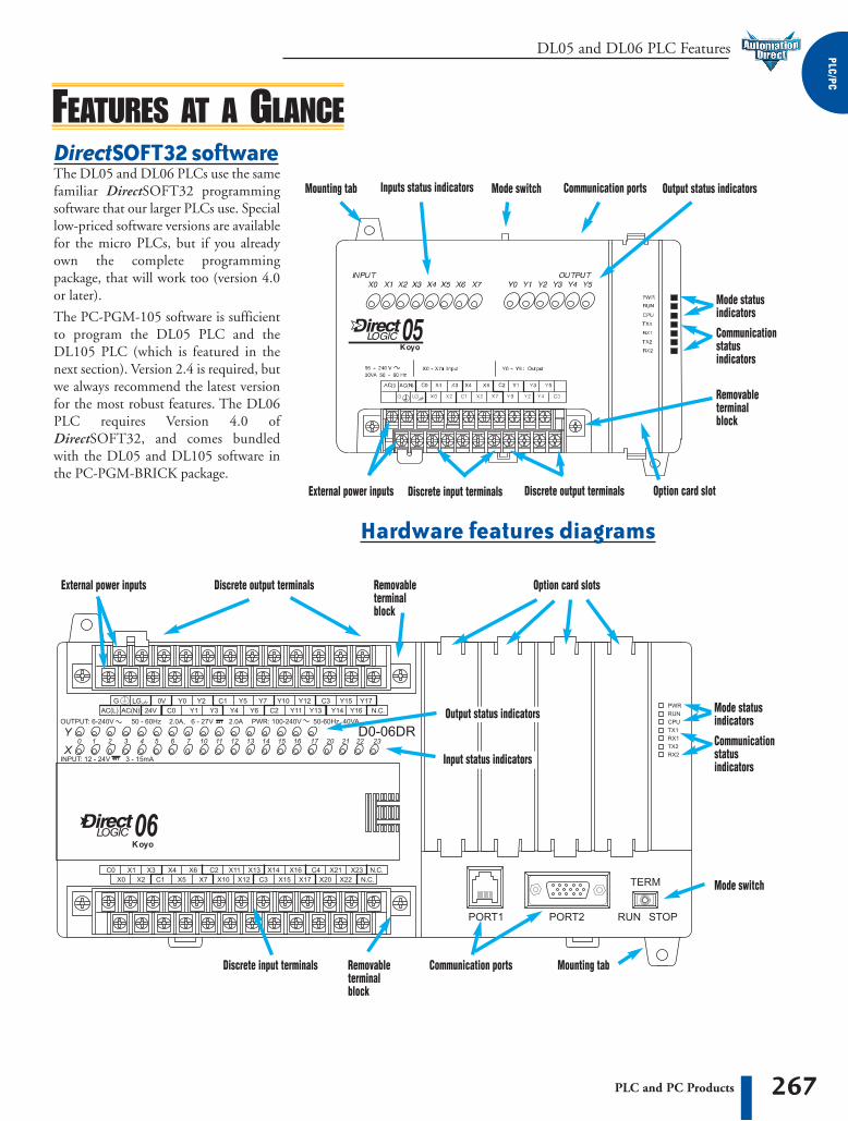
Mounting tab Inputs status indicators Mode switch Communication ports
Output status indicators
Mounting tab
Input status indicators
Mode switch
Communication ports
External power inputs
External power inputs
Discrete input terminals
Discrete input terminals
Discrete output terminals
Discrete output terminals
Option card slot
Hardware features diagrams
DirectSOFT32 softwareThe DL05 and DL06 PLCs use the samefamiliar DirectSOFT32 programmingsoftware that our larger PLCs use. Speciallow-priced software versions are availablefor the micro PLCs, but if you alreadyown the complete programmingpackage, that will work too (version 4.0or later).
The PC-PGM-105 software is sufficientto program the DL05 PLC and theDL105 PLC (which is featured in thenext section). Version 2.4 is required, butwe always recommend the latest versionfor the most robust features. The DL06PLC requires Version 4.0 ofDirectSOFT32, and comes bundledwith the DL05 and DL105 software inthe PC-PGM-BRICK package.
Option card slots
1.5"38mm
min
1.5"38mm
min
1.5"38mm
min
2"50mm
min
2"50mm
min
2"50mm
min
DL05 and DL06 PLC Dimensions and Installation1
-8
00
-6
33
-0
40
5
268 PLC and PC Products
EarthgroundPanel
Panel or singlepoint ground
Ground braid cop-per lugs
Star washers
Panel ground terminal
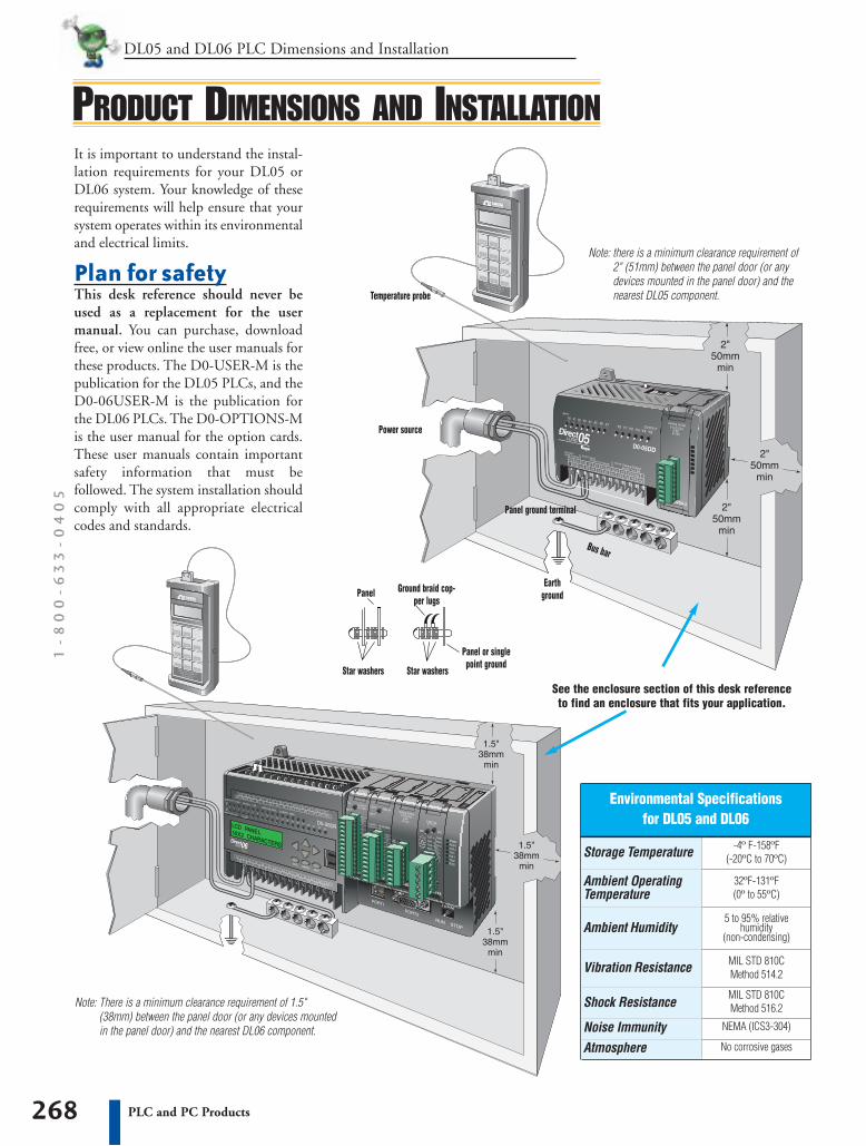
Note: There is a minimum clearance requirement of 1.5"(38mm) between the panel door (or any devices mountedin the panel door) and the nearest DL06 component.
Note: there is a minimum clearance requirement of2" (51mm) between the panel door (or anydevices mounted in the panel door) and thenearest DL05 component.Temperature probe
Power source
Star washers
Bus bar
It is important to understand the instal-lation requirements for your DL05 orDL06 system. Your knowledge of theserequirements will help ensure that yoursystem operates within its environmentaland electrical limits.
Plan for safetyThis desk reference should never beused as a replacement for the usermanual. You can purchase, downloadfree, or view online the user manuals forthese products. The D0-USER-M is thepublication for the DL05 PLCs, and theD0-06USER-M is the publication forthe DL06 PLCs. The D0-OPTIONS-Mis the user manual for the option cards.These user manuals contain importantsafety information that must befollowed. The system installation shouldcomply with all appropriate electricalcodes and standards.
Environmental Specificationsfor DL05 and DL06
Storage Temperature -4º F-158ºF(-20ºC to 70ºC)
Ambient OperatingTemperature
32ºF-131ºF(0º to 55ºC)
Ambient Humidity5 to 95% relative
humidity(non-condensing)
Vibration Resistance MIL STD 810CMethod 514.2
Shock Resistance MIL STD 810CMethod 516.2
Noise Immunity NEMA (ICS3-304)
Atmosphere No corrosive gases
PRODUCT DIMENSIONS AND INSTALLATION
See the enclosure section of this desk referenceto find an enclosure that fits your application.
269PLC and PC Products
DL05 and DL06 PLC Dimensions and Installation PLC/PC
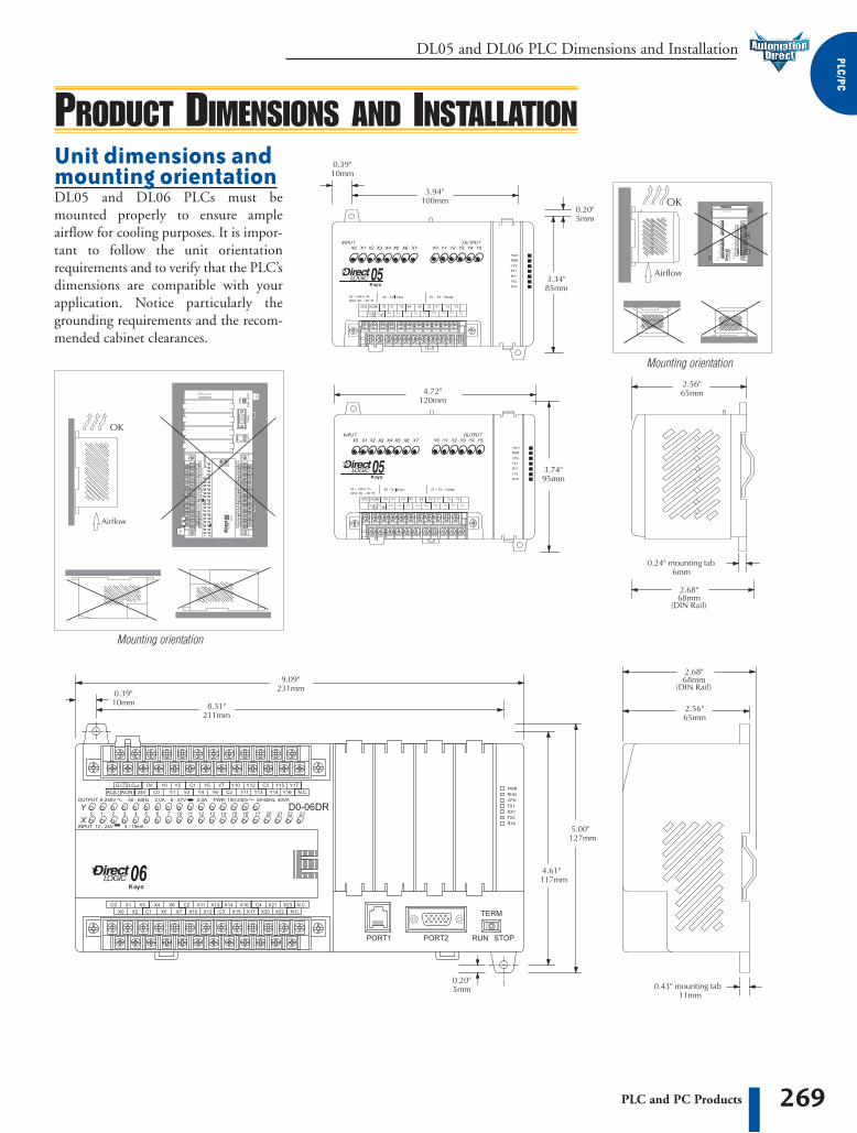
PRODUCT DIMENSIONS AND INSTALLATIONUnit dimensions andmounting orientationDL05 and DL06 PLCs must bemounted properly to ensure ampleairflow for cooling purposes. It is impor-tant to follow the unit orientationrequirements and to verify that the PLC’sdimensions are compatible with yourapplication. Notice particularly thegrounding requirements and the recom-mended cabinet clearances.
Mounting orientation
Mounting orientation

DL05 and DL06 PLC I/O Types1
-8
00
-6
33
-0
40
5
270 PLC and PC Products
Sinking/sourcingIf you are using a DC field device, youshould consider whether that devicerequires a sinking or sourcing PLC I/Oconfiguration. For more information onsinking and sourcing concepts, pleaserefer to the Appendix of this catalog.
Sink/source inputs — All built-in DCinputs on the DL05 and DL06 microPLCs can be wired in a sinking orsourcing configuration. However, allinputs on a single common must use thesame configuration. In some cases, theDC inputs on option cards are fixed assinking or sourcing. Refer to the table onthe next page.
Sinking outputs — All built-in DCoutputs on the DL05 are sinking. TheDL06 family offers three PLCs withsinking DC outputs, and one withsourcing outputs.
Sourcing outputs — The DL06 PLCfamily includes the D0-06DD2 withsourcing outputs. If a sourcing output isrequired, you might also consider usingeither the D0-xxTD2 option card withsourcing outputs, which can also beinstalled in a DL05 or DL06 PLC.
The DL05 and DL06 product familiesoffer a number of different I/O configu-rations. Choose the configuration that isright for your application. Also, keep inmind that both the DL05 and the DL06PLCs offer the ability to add I/O withthe use of option cards.
Fixed discrete I/OAll DL05 micro PLCs have eight built-ininputs and six built-in outputs on thebase unit. The DL06 micro PLCs have20 built-in inputs and 16 built-inoutputs on the base unit. We offer themost common I/O types for your conve-nience, including AC inputs and outputs,DC sinking and sourcing inputs andoutputs, and relay outputs. Refer to thetables to the right to see the I/O combi-nations available and their voltage ranges.
Option card slotsThe DL05 has one option card slot andthe DL06 has four option card slots.Check out the discrete and analog I/Oyou can add by purchasing inexpensiveoption cards. Option card specialtymodules are also available and arediscussed later in this section.
Automaticallyassigned addressesThe DL05 uses automatic addressing, sofor the vast majority of applications,there is no setup required. We use octaladdressing for our products, whichmeans there are no 8s or 9s. The DL05’seight input points use addresses X0-X7,and the six output points use addressesY0-Y5. Similarly, the DL06 usesaddresses X0-X23 and Y0-Y17.
Review the I/O specsand wiring diagramsThe Base Unit I/O tables give a briefdescription of the I/O combinationsoffered for the DL05 and DL06 PLCs.The I/O specifications are discussed inmore detail later in this section.
High-speed inputsand pulse outputsDL05s and DL06s with DC inputs offerhigh-speed input features, and DC outputunits offer pulse output features. The firstthree DC inputs on the DL05 PLCs are setup by default as filtered inputs with a 10 msfilter. Likewise, the first four DC inputs onthe DL06 PLCs are set to the same defaultvalue. By entering a setup code in a special V-memory location, you can choose otherfeatures. In some modes of operation, youhave a choice as to how you use each point.For example, if you use X0 as an up counter,you can use X2 as a reset input for thecounter or as a filtered discrete input. If thesefeatures interest you, take a look at thedetailed high-speed I/O descriptions foundlater in this section.
DL05 Base Unit I/O Table
Part Number I/O type/commons
Sink orsource
D0-05AR AC/2 N/A 90-120VAC Relay/2 N/A
D0-05DR DC/2Sink orSource 12-24VDC Relay/2 N/A
D0-05AD AC/2 N/A 90-120VAC DC/1 Sink
D0-05DD DC/2Sink orSource 12-24VDC DC/1 Sink
D0-05AA AC/1 N/A 90-120VAC AC/2 N/A
D0-05DA DC/2Sink orSource 12-24VDC AC/2 N/A
Inputs
Voltageranges
I/O type/commons
Sinkor
source
Outputs
D0-05DR-D
D0-05DD-D
DC/2Sink orSource 12-24VDC Relay/2 N/A
DC/2Sink orSource 12-24VDC DC/1 Sink
CHOOSING THE I/O TYPE
Voltage/current ratings
6-27VDC, 2A6-240VAC, 2A
6-27VDC, 2A6-240VAC, 2A
6-27VDC, 0.5A (Y0-Y1)6-27VDC, 1.0A (Y2-Y5)
6-27VDC, 0.5A (Y0-Y1)6-27VDC, 1.0A (Y2-Y5)
17-240VAC 47-63Hz 0.5A
17-240VAC 47-63Hz 0.5A
6-27VDC, 2A6-240VAC, 2A
6-27VDC, 0.5A (Y0-Y1)6-27VDC, 1.0A (Y2-Y5)
271PLC and PC Products
DL05 and DL06 PLC I/O Types PLC/PC
CHOOSING THE I/O TYPEDL06 Base Unit I/O Table
Part Number I/O Type/Commons
Sink orsource
D0-06AA AC/5 N/A 90-120VAC AC/4 N/A
D0-06AR AC/5N/A
90-120VAC Relay/4 N/A
D0-06DA DC/5 Sink orsource 12-24VDC AC/4 N/A 17-240VAC, 0.5A
47-63Hz
D0-06DD1 DC/5Sink orsource 12-24VDC DC/4 Sink 6-27VDC, 0.5A (Y0-Y1)
6-27VDC, 1.0A (Y2-Y17)
D0-06DD2 DC/5 Sink orsource 12-24VDC DC/4 Source 12-24VDC, 0.5A (Y0-Y1)
12-24VDC, 1.0A (Y2-Y17)
D0-06DR DC/5Sink orsource 12-24VDC Relay/4 N/A 6-27VDC, 2A
6-240VAC, 2A
Inputs
VoltageRanges
I/O Type/Commons
Sink orSource Voltage/current ratings
Outputs
17-240VAC, 0.5A 47-63Hz
6-27VDC, 2A6-240VAC, 2A
D0-06DD1-D
D0-06DR-D
DC/5Sink orsource 12-24VDC DC/4 Sink 6-27VDC, 0.5A (Y0-Y1)
6-27VDC, 1.0A (Y2-Y17)
DC/5Sink orsource 12-24VDC Relay/4 N/A 6-27VDC, 2A
6-240VAC, 2A
Discrete I/O Option Cards
Part Number I/O Type/Number/
CommonsSink orsource
D0-07CDR DC/4/1 Sink orsource 12-24VDC Relay/3/1 N/A
D0-08CDD1 DC/4/2 Sink orsource 12-24VDC DC/4/2 Sink
D0-08TR N/A N/A N/A Relay/8/2 N/A 6-27VDC, 1A6-240VAC, 1A
D0-10ND3 DC/10/2 Sink orsource 12-24VDC N/A N/A N/A
D0-10TD1 N/A N/A N/A DC/10/2 Sink 6-27VDC, 0.3A
Inputs
VoltageRanges
I/O Type/Number/
CommonsSink orSource Voltage/Current Ratings
Outputs
6-27VDC, 1A6-240VAC, 1A
6-27VDC, 0.3A
D0-10TD2
D0-16ND3
N/A N/A N/A DC/10/2 Source 12-24VDC, 0.3A
DC/16/4 Sink orsource 20-28VDC N/A N/A N/A
D0-16TD1
D0-16TD2
N/A N/A N/A
N/A N/A N/A
DC/16/2
DC/16/2
Sink
Source
6-27VDC, 0.1A
12-24VDC, 0.1A
Analog I/O Option Cards
Part NumberNo.
Inputs
Input Type
F0-04AD-1
F0-4AD2DA-1
F0-2AD2DA-2
F0-4AD2DA-2
4
4
4 0-20mA or4-20mA
0-20mA or4-20mA
2 0-5VDC or0-10VDC
0-5VDC or0-10VDC
2 0-20mA or4-20mA
OutputsOutputType
N/A
0-5VDC or0-10VDC
0-5VDC or0-10VDC
No.
0
2
2
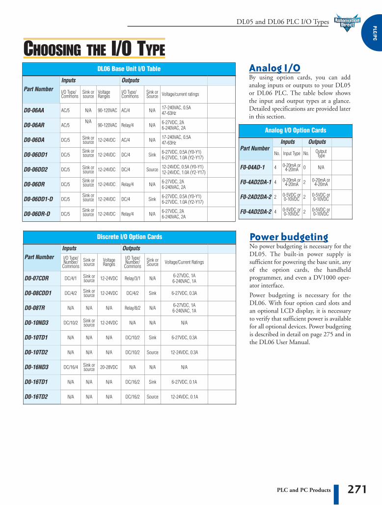
Analog I/OBy using option cards, you can addanalog inputs or outputs to your DL05or DL06 PLC. The table below showsthe input and output types at a glance.Detailed specifications are provided laterin this section.
Power budgetingNo power budgeting is necessary for theDL05. The built-in power supply issufficient for powering the base unit, anyof the option cards, the handheldprogrammer, and even a DV1000 oper-ator interface.
Power budgeting is necessary for theDL06. With four option card slots andan optional LCD display, it is necessaryto verify that sufficient power is availablefor all optional devices. Power budgetingis described in detail on page 275 and inthe DL06 User Manual.

DL05 and DL06 PLC Communications1
-8
00
-6
33
-0
40
5
272 PLC and PC Products
All DL05 and DL06 PLCs have built-innetworking capability. The DL05 familyoffers two 6-pin, RS-232C ports. Youcan use these ports for programming,networking, or connecting an operatorinterface device. The RS232C portssupport point-to-point communicationsusing the optional D0-CBL cable. If youneed to create a multi-drop network or ifyou require longer distances betweendevices, you can use the FA-ISONET ateach DL05 to convert the RS232Csignal to RS422 or RS485.
The DL06 family of PLCs offers evengreater communications flexibility. Port1 is a fixed baud rate port identical toport 1 on the DL05 PLCs, but port 2 isa multi-function port that can be used asRS232C, RS422, or RS485 withoutusing external converters. This allowsyou to create multi-drop networks withminimal installation headaches.
The DL06 PLCs have next generationsimplified instructions for handling bothMODBUS RTU and ASCII communi-cations. The new ASCII instruction setmakes it practical to connect an ASCIIinput or output device to the DL06. Seepage 274 for more information.
Master Slave
maximum distance 50ft (15m)
Point-to-point
Multi-drop
10’ crossover cable = D0-CBL
Maximum distance of 3,300 ft. (1000m)
NETWORKING THE DL05 AND DL06
Protocols supportedEach port is capable of communicatingusing K-sequence, DirectNET andMODBUS protocols. Port 1 can only bea slave for each of the protocols. Port 2can serve as a K-sequence slave or anetwork master or slave for eitherDirectNET or MODBUS RTU protocols.
DeviceNetWe also offer an option card that allowsyou to connect a DL05 or DL06 PLC toa DeviceNet network as a slave device.Our D0-DEVNETS option card plugsinto any DL05 or DL06 PLC. For moreinformation, see page 296.
273PLC and PC Products
DL05 and DL06 PLC Communications PLC/PC
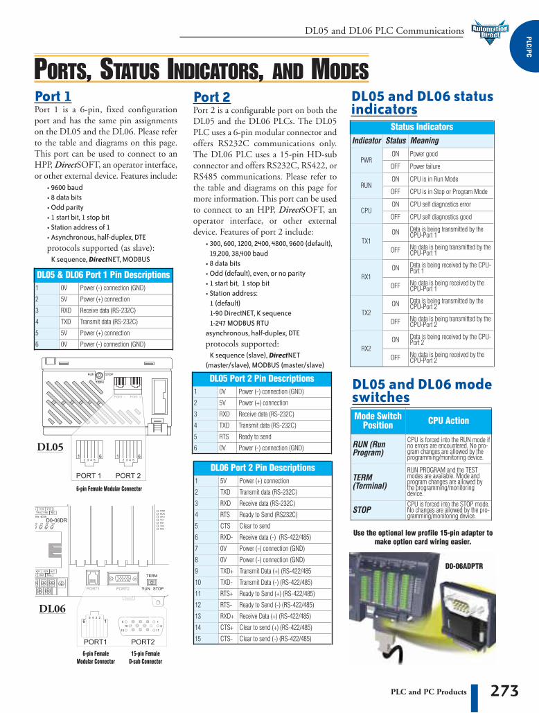
Status IndicatorsIndicator
PWRON Power good
CPUON CPU self diagnostics error
TX1ON Data is being transmitted by the
CPU-Port 1
RX1ON Data is being received by the CPU-
Port 1
TX2ON Data is being transmitted by the
CPU-Port 2
RX2ON Data is being received by the CPU-
Port 2
OFF
OFF
OFF
OFF
OFF
OFF
Power failure
Meaning
CPU is in Stop or Program Mode
CPU self diagnostics good
No data is being transmitted by theCPU-Port 1
No data is being received by theCPU-Port 1
No data is being transmitted by theCPU-Port 2
OFF No data is being received by theCPU-Port 2
DL05 & DL06 Port 1 Pin Descriptions1 0V Power (-) connection (GND)
2 5V Power (+) connection
3 RXD Receive data (RS-232C)
4 TXD Transmit data (RS-232C)
DL05 Port 2 Pin Descriptions1 0V Power (-) connection (GND)
2 5V Power (+) connection
3 RXD Receive data (RS-232C)
4 TXD Transmit data (RS-232C)
5 RTS Ready to send
6 0V Power (-) connection (GND)
Mode SwitchPosition CPU Action
RUN (RunProgram)
CPU is forced into the RUN mode ifno errors are encountered. No pro-gram changes are allowed by theprogramming/monitoring device.
TERM(Terminal)
RUN PROGRAM and the TESTmodes are available. Mode andprogram changes are allowed bythe programming/monitoringdevice.
STOPCPU is forced into the STOP mode.No changes are allowed by the pro-gramming/monitoring device.
Status
ON CPU is in Run ModeRUN
PORTS, STATUS INDICATORS, AND MODES
Use the optional low profile 15-pin adapter tomake option card wiring easier.
DL05 and DL06 statusindicators
DL05 and DL06 modeswitches
DL06 Port 2 Pin Descriptions1 5V Power (+) connection
2 TXD Transmit data (RS-232C)
5 CTS Clear to send
6 RXD- Receive data (-) (RS-422/485)
7
8
9
10
11
12
13
14
15
0V
0V
TXD+
TXD-
RTS+
RTS-
RXD+
CTS+
CTS-
Power (-) connection (GND)
Power (-) connection (GND)
Transmit Data (+) (RS-422/485
Transmit Data (-) (RS-422/485)
Ready to Send (+) (RS-422/485)
Ready to Send (-) (RS-422/485)
Receive Data (+) (RS-422/485)
Clear to send (+) (RS-422/485)
Clear to send (-) (RS-422/485)
6-pin Female Modular Connector
6-pin FemaleModular Connector
15-pin Female D-sub Connector
5
6 Power (-) connection (GND)0V
Power (+) connection5V
3
4
RXD
RTS Ready to Send (RS232C)
Receive data (RS-232C)
Port 1 Port 1 is a 6-pin, fixed configurationport and has the same pin assignmentson the DL05 and the DL06. Please referto the table and diagrams on this page.This port can be used to connect to anHPP, DirectSOFT, an operator interface,or other external device. Features include:
• 9600 baud• 8 data bits• Odd parity• 1 start bit, 1 stop bit• Station address of 1• Asynchronous, half-duplex, DTEprotocols supported (as slave):
K sequence, DirectNET, MODBUS
Port 2 Port 2 is a configurable port on both theDL05 and the DL06 PLCs. The DL05PLC uses a 6-pin modular connector andoffers RS232C communications only.The DL06 PLC uses a 15-pin HD-subconnector and offers RS232C, RS422, orRS485 communications. Please refer tothe table and diagrams on this page formore information. This port can be usedto connect to an HPP, DirectSOFT, anoperator interface, or other externaldevice. Features of port 2 include:
• 300, 600, 1200, 2400, 4800, 9600 (default), 19,200, 38,400 baud
• 8 data bits• Odd (default), even, or no parity• 1 start bit, 1 stop bit• Station address:
1 (default)1-90 DirectNET, K sequence1-247 MODBUS RTU
asynchronous, half-duplex, DTEprotocols supported:
K sequence (slave), DirectNET(master/slave), MODBUS (master/slave)
DL05
DL06
D0-06ADPTR

DL06 PLC Communications1
-8
00
-6
33
-0
40
5
274 PLC and PC Products
ASCII AND MODBUS INSTRUCTIONSNew ASCII instructions for DL06The DL06 PLC supports several neweasy to use instructions, which allowASCII strings to be read into or writtenfrom the communication ports.
Raw ASCII: Port 2 can be used for eitherreading or writing raw ASCII strings,but not for both.
Embedded ASCII: With the newinstructions, you can use the DL06 PLCto locate ASCII strings embedded withina supported protocol (via Port 2).
Receiving ASCII strings1. ASCII IN (AIN) - This instruction
configures Port 2 for raw ASCII inputstrings, with parameters such as fixedand variable length ASCII strings,termination characters, byte swappingoptions, and instruction control bits.Use barcode scanners, weight scales,etc., to write rawASCII inputstrings into Port 2based on the AINinstruction’s para-meters.
2. Write embeddedASCII strings directlyto V-memory froman external HMI (orsimilar masterdevice). The ASCIIstring is transmittedthrough Port 2 usingany supportedc o m m u n i c a t i o n sprotocol. Thismethod uses the familiar RX/WXinstructions previously available.
3. If the DL06 is used as a networkmaster, the Network Read instruction(RX) can be used to read embeddedASCII data from a network slavedevice. Again, the ASCII string wouldbe transmitted through Port 2, usingany supported communicationsprotocol.
New MODBUS RTUinstructions for DL06The DL06 PLC supports new MODBUSRead/Write instructions that simplifysetup. The MRX and MWX instructionsallow you to use native MODBUSaddressing, eliminating the need for octalto decimal conversions.
Function Codes 05 and 06 and the abilityto read Slave Exception Codes have beenadded. These flexible instructions allowthe user to select the following parameterswithin one instruction window:
• 584/984 or 484 MODBUS data type• Slave node (0-247)• Function code• Starting master/slave memory address• Number of bits• Exception code starting address
Writing ASCII strings1. Print from V-memory (PRINTV) -
Use this instruction to write rawASCII strings out of Port 2 to adisplay panel,serial printer,etc. The instruc-tion features thestarting V-m e m o r yaddress, stringlength, bytes w a p p i n goptions, etc. When the instruction’spermissive bit is enabled, the string iswritten to Port 2.
2. Print to V-memory (VPRINT) - Usethis instruction to create pre-codedASCII strings in the PLC (e.g. alarmmessages). When the instruction’spermissive bit is enabled, the messageis loaded into a pre-defined V-memory address location. Then thePRINTV instruction may be used towrite the pre-coded ASCII string outof Port 2. American, European, andAsian Time/Date stamps aresupported.
3. Print Message (PRINT) - Thisexisting instruction can be used tocreate pre-coded ASCII strings in thePLC. When the instruction’s permis-sive bit is enabled, the string is writtento Port 2. The VPRINT/PRINTVinstruction combination is morepowerful and flexible than the PRINTinstruction.
4. If the DL06 PLC is a network master,the Network Write (WX) can be usedto write embedded ASCII data to anHMI or slave device directly from V-memory. This is done via a supportedcommunications protocol using Port 2.
Other new ASCII instructionsASCII Find (AFIND) - Finds where aspecific portion of the ASCII string islocated in continuous V-memoryaddresses.
ASCII Extract (AEX) - Extracts a specificportion (usually some data value) fromthe ASCII find location or other knownASCII data location.
Compare V-memory (CMPV) - Thisinstruction is used to compare twoblocks of V-memory addresses and isusually used to detect a change in anASCII string. Compared data types mustbe of the same format (e.g. BCD, ASCII,etc.).
Swap Bytes (SWAPB) - Swaps V-memory bytes on ASCII data that waswritten directly to V-memory from anexternal HMI or similar master devicevia a communications protocol. TheAIN and AEX instructions have a built-in byte swap feature.

275PLC and PC Products
DL06 PLC Power Budget PLC/PC
POWER BUDGETING FOR THE DL06DL06 Power Consumed
by Option CardsPart Number
D0-07CDR 130mA none
D0-08CDD1 100mA none
D0-08TR 280mA none
D0-10ND3 35mA none
D0-10TD1 150mA none
5 VDC (mA)
D0-10TD2
D0-16ND3
150mA none
35mA none
D0-16TD1
D0-16TD2
F0-04AD-1
F0-2AD2DA-2
F0-4AD2DA-1
F0-4AD2DA-2
50mA
100mA
DL06 Base Unit Power RequiredPart Number
D0-06AA 800mA none
D0-06AR 900mA none
D0-06DA 800mA none
D0-06DD1 600mA 280mA*
D0-06DD2 600mA none
D0-06DR 950mA none
5 VDC 24 VDC
D0-06DD1-D
D0-06DR-D
600mA none
950mA none
DL06 Power Supplied by Base Units
Part Number
D0-06xx1500mA 300mA
2000mA 200mA
D0-06xx-D 1500mA none
5 VDC (mA) 24 VDC (mA)
The DL06 has four option card slots. Todetermine whether the combination ofcards you select will have sufficientpower, you will need to perform a powerbudget calculation.
Power suppliedPower is supplied from two sources, theinternal base unit power supply and, ifrequired, an external supply (customerfurnished). The D0-06xx (AC powered)PLCs supply a limited amount of24VDC power. The 24VDC output canbe used to power external devices.
For power budgeting, start by consid-ering the power supplied by the baseunit. All DL06 PLCs supply the sameamount of 5VDC power. Only the ACunits offer 24VDC auxiliary power.
Be aware of the trade-off between 5VDCpower and 24VDC power. The amountof 5VDC power available depends on theamount of 24VDC power being used,and the amount of 24VDC power avail-able depends on the amount of 5VDCpower consumed. Determine the amountof internally supplied power from thetable to the right.
Power required bybase unitBecause of the different I/O configura-tions available in the DL06 family, thepower consumed by the base unit itselfvaries from model to model. Subtract theamount of power required by the baseunit from the amount of power suppliedby the base unit. Be sure to subtract5VDC and 24VDC amounts.
Power required byoption cardsNext, subtract the amount of powerrequired by the option cards you areplanning to use. Again, remember tosubtract both 5VDC and 24VDC.
If your power budget analysis showssurplus power available, you should havea workable configuration.
24 VDC (mA)
none
none
none
30mA
40mA
none
200mA
200mA
50mA
100mA
D0-DEVNETS 45mA
DL06 Power Consumed by Other Devices
Part Number
D0-06LCD 50mA none
D0-HPP 200mA none
5 VDC (mA) 24 VDC (mA)
noneDV1000 150mA none
* Only if auxiliary 24VDC power is connected to V+ terminal.
Power Budgeting Example5VDC power (mA) 24VDC power (mA)Power Source
D0-06DD1(select row A or row B)
Current Required
1500mA 2000mA
300mA 200mA
AB
5VDC power (mA) 24VDC power (mA)D0-06DD1 600mA 280mA*
D0-16ND3
D0-10TD1
D0-08TR
F0-4AD2DA-1
D0-06LCD
Total Used
0
1215mA
50mA
100mA
280mA
150mA
35mA
0
0
0
0
280mA
Remaining285mAA
B 785mA note 120mA
* Auxiliary 24VDC used to power V+ terminal of D0-06DD1 sinking outputs.
Note 1: If the PLC’s auxiliary 24VDC power source is used to powerthe sinking outputs, use power choice A, above.
DL06 PLC LCD Display1
-8
00
-6
33
-0
40
5
276 PLC and PC Products
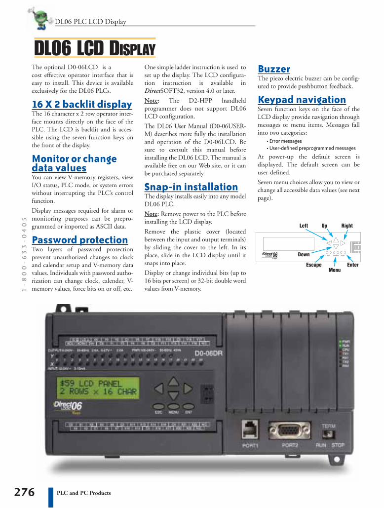
The optional D0-06LCD is acost effective operator interface that iseasy to install. This device is availableexclusively for the DL06 PLCs.
16 X 2 backlit displayThe 16 character x 2 row operator inter-face mounts directly on the face of thePLC. The LCD is backlit and is acces-sible using the seven function keys onthe front of the display.
Monitor or changedata valuesYou can view V-memory registers, viewI/O status, PLC mode, or system errorswithout interrupting the PLC’s controlfunction.
Display messages required for alarm ormonitoring purposes can be prepro-grammed or imported as ASCII data.
Password protectionTwo layers of password protectionprevent unauthorized changes to clockand calendar setup and V-memory datavalues. Individuals with password autho-rization can change clock, calender, V-memory values, force bits on or off, etc.
DL06 LCD DISPLAYBuzzerThe piezo electric buzzer can be config-ured to provide pushbutton feedback.
Keypad navigationSeven function keys on the face of theLCD display provide navigation throughmessages or menu items. Messages fallinto two categories:
• Error messages• User-defined preprogrammed messages
At power-up the default screen isdisplayed. The default screen can beuser-defined.
Seven menu choices allow you to view orchange all accessible data values (see nextpage).
One simple ladder instruction is used toset up the display. The LCD configura-tion instruction is available inDirectSOFT32, version 4.0 or later.
Note: The D2-HPP handheldprogrammer does not support DL06LCD configuration.
The DL06 User Manual (D0-06USER-M) describes more fully the installationand operation of the D0-06LCD. Besure to consult this manual beforeinstalling the DL06 LCD. The manual isavailable free on our Web site, or it canbe purchased separately.
Snap-in installationThe display installs easily into any modelDL06 PLC.
Note: Remove power to the PLC beforeinstalling the LCD display.
Remove the plastic cover (locatedbetween the input and output terminals)by sliding the cover to the left. In itsplace, slide in the LCD display until itsnaps into place.
Display or change individual bits (up to16 bits per screen) or 32-bit double wordvalues from V-memory.
Up Right
Down
MenuEnterEscape
Left
277PLC and PC Products
DL06 PLC LCD Display PLC/PC
DL06 LCD DISPLAYMenu choicesPressing the Menu key takes you to thelast accessed menu (or the first menuselection, if you haven’t previouslyaccessed a menu). Each time you pressthe Menu key (or if you simply hold themenu key down) the display will stepthrough all menu choices.
There are seven built-in menus. Use theMenu key to locate the menu you need,and press the Enter key to view orchange values.
From the default screen or a messagescreen, press and hold the Menu key. Thedisplay will scroll through the followingchoices:
M1 : PLC informationM2 : System configurationM3 : MonitorM4 : Calendar R/WM5 : Password operationM6 : Error history readM7 : LCD test and set
Make a menu selection by pressing theEnter key. Change data values using thedirection arrow keys.
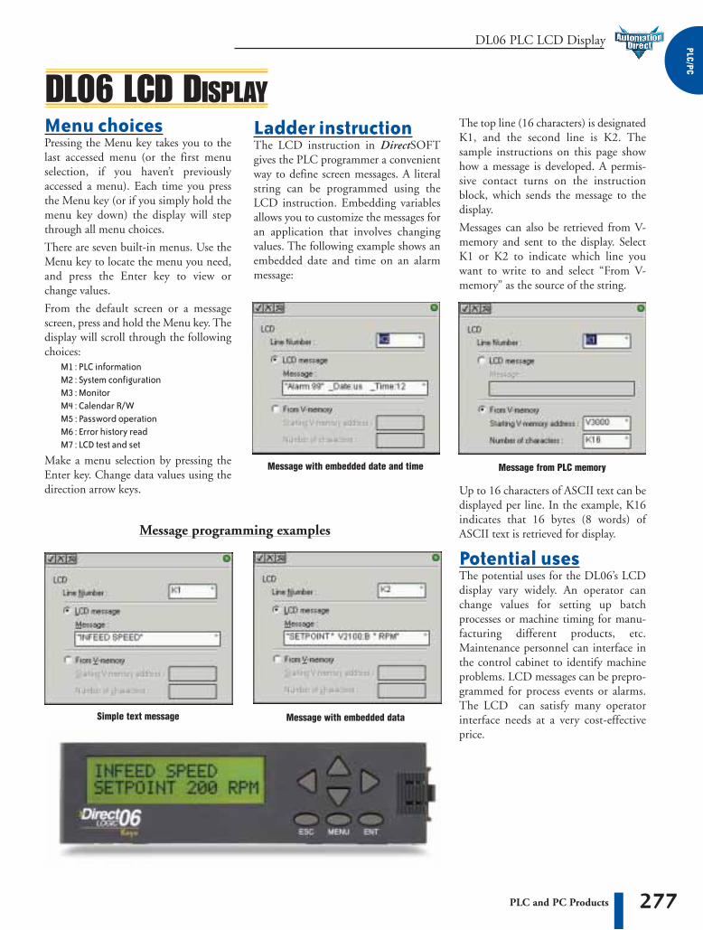
Ladder instructionThe LCD instruction in DirectSOFTgives the PLC programmer a convenientway to define screen messages. A literalstring can be programmed using theLCD instruction. Embedding variablesallows you to customize the messages foran application that involves changingvalues. The following example shows anembedded date and time on an alarmmessage:
Message programming examples
The top line (16 characters) is designatedK1, and the second line is K2. Thesample instructions on this page showhow a message is developed. A permis-sive contact turns on the instructionblock, which sends the message to thedisplay.
Messages can also be retrieved from V-memory and sent to the display. SelectK1 or K2 to indicate which line youwant to write to and select “From V-memory” as the source of the string.
Up to 16 characters of ASCII text can bedisplayed per line. In the example, K16indicates that 16 bytes (8 words) ofASCII text is retrieved for display.
Potential usesThe potential uses for the DL06’s LCDdisplay vary widely. An operator canchange values for setting up batchprocesses or machine timing for manu-facturing different products, etc.Maintenance personnel can interface inthe control cabinet to identify machineproblems. LCD messages can be prepro-grammed for process events or alarms.The LCD can satisfy many operatorinterface needs at a very cost-effectiveprice.
Message from PLC memoryMessage with embedded date and time
Message with embedded dataSimple text message
DL05 and DL06 PLC Accessories1
-8
00
-6
33
-0
40
5
278 PLC and PC Products
ACCESSORIES
DL06 15-pin high density D-sub port adapter
D0-06ADPTR
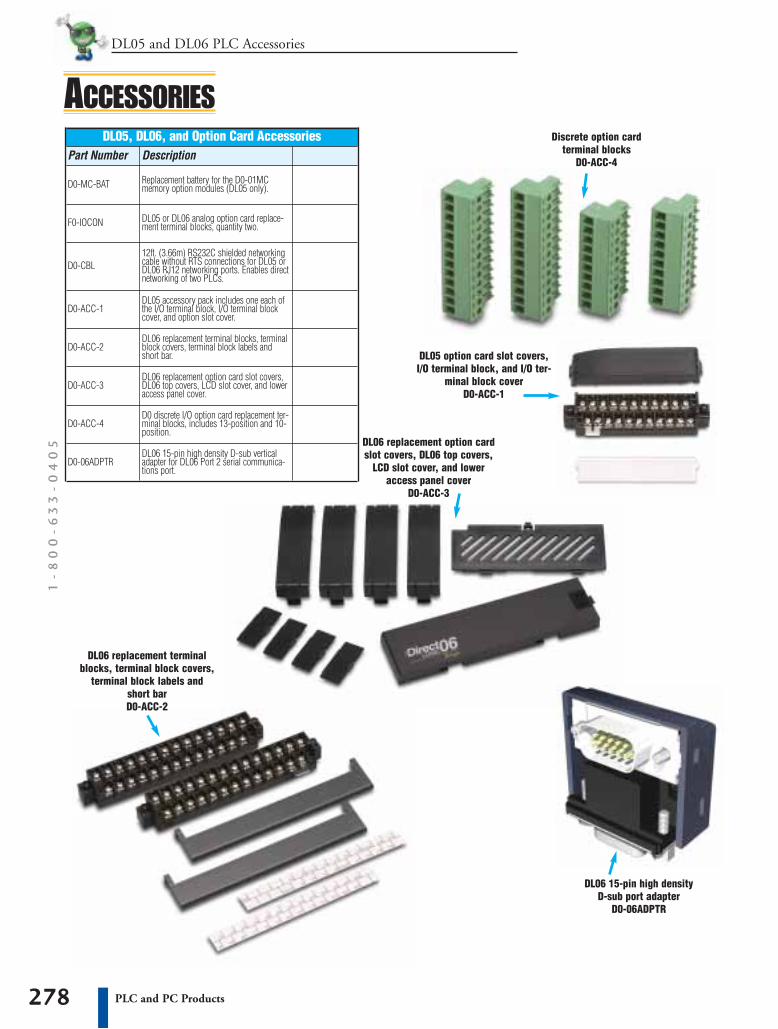
DL05, DL06, and Option Card AccessoriesPart Number Description
DL06 replacement terminal blocks, terminalblock covers, terminal block labels andshort bar.
Discrete option card terminal blocks
D0-ACC-4
DL06 replacement option cardslot covers, DL06 top covers,
LCD slot cover, and loweraccess panel cover
D0-ACC-3
DL05 option card slot covers,I/O terminal block, and I/O ter-
minal block coverD0-ACC-1
Replacement battery for the D0-01MCmemory option modules (DL05 only).D0-MC-BAT
D0-ACC-1
F0-IOCON
D0-CBL
D0-ACC-2
D0-ACC-3
D0-ACC-4
D0-06ADPTR
DL05 or DL06 analog option card replace-ment terminal blocks, quantity two.
12ft. (3.66m) RS232C shielded networkingcable without RTS connections for DL05 orDL06 RJ12 networking ports. Enables directnetworking of two PLCs.
DL05 accessory pack includes one each ofthe I/O terminal block, I/O terminal blockcover, and option slot cover.
DL06 replacement option card slot covers,DL06 top covers, LCD slot cover, and loweraccess panel cover.
D0 discrete I/O option card replacement ter-minal blocks, includes 13-position and 10-position.
DL06 15-pin high density D-sub verticaladapter for DL06 Port 2 serial communica-tions port.
DL06 replacement terminalblocks, terminal block covers,
terminal block labels andshort barD0-ACC-2

287PLC and PC Products
DL06 PLC I/O Specifications PLC/PC
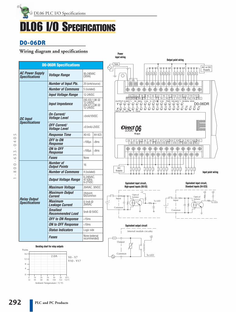
DL06 I/O SPECIFICATIONSD0-06AA Wiring diagram and specifications
Number of Input Pts. 20
Number of CommonsInput Voltage RangeFrequency Range
Input Current
OFF Current/Voltage Level
OFF to ON Response ON to OFFResponse
8mA @ 100 VAC,50 Hz 10mA @ 100VAC, 60Hz
Fuses
5 (isolated)
90-120VAC
47-63Hz
<2mA/20VAC
<40ms
<40ms
None
On Current/VoltageLevel
Number of Commons
Output Voltage Range
Peak Voltage
ON Voltage Drop
Maximum Current
Maximum Leakage Current
OFF to ON ResponseON to OFF Response
Minimum Load
Fuses
Maximum Inrush Current
>6mA/75VAC
4 (isolated)
17-240VAC 47-63Hz
264VAC
1.5 VAC>50mA4.0VAC<50mA
0.5A/pt2.0A/common
None (externalrecommended)
10mA
<1ms + 1/2 cycle
<1ms
10A for 10ms
4mA at 264VAC
D0-06AA Specifications
AC OutputSpecifications
AC InputSpecifications
AC Power SupplySpecifications Voltage Range 95-240VAC
(30VA)
Number of OutputPoints 16
Equivalent input circuit
Derating chart for AC outputs
Equivalent output circuit
Powerinput wiring
Input point wiring
Output point wiring
DL06 PLC I/O Specifications1
-8
00
-6
33
-0
40
5
288 PLC and PC Products
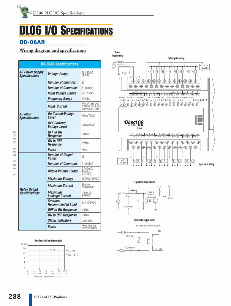
DL06 I/O SPECIFICATIONS
Number of Input Pts. 20
Number of CommonsInput Voltage RangeFrequency Range
Input Current
OFF Current/Voltage Level
OFF to ON Response ON to OFFResponse
8mA @ 100 VACat 50 Hz 10mA @100 VAC at 60Hz
Fuses
5 (isolated)
90-120VAC
47-63Hz
<2mA/20VAC
<40ms
<40ms
None
On Current/VoltageLevel
Number of Commons
Output Voltage Range
Maximum Voltage
Maximum Current
Maximum Leakage CurrentSmallest Recommended LoadOFF to ON ResponseON to OFF ResponseStatus Indicators
Fuses
>6mA/75VAC
4 (isolated)
6-240VAC,47-63Hz6-27VDC
264VAC, 30VDC
2A/point6A/common
0.1mA @246VAC
5mA @ 5VDC
None (externalrecommended)
Logic side
<10ms
<15ms
D0-06AR Specifications
Relay OutputSpecifications
AC InputSpecifications
AC Power SupplySpecifications Voltage Range 95-240VAC
(30VA)
Number of OutputPoints 16
D0-06AR Wiring diagram and specifications
Equivalent input circuit
Derating chart for relay outputs
Equivalent output circuit
Powerinput wiring
Input point wiring
Output point wiring

289PLC and PC Products
DL06 PLC I/O Specifications PLC/PC
DL06 I/O SPECIFICATIONSD0-06DA Wiring diagram and specifications
Derating chart for AC outputsEquivalent output circuit
Number of Input Pts. 20 (sink/source)
Number of CommonsInput Voltage Range
Frequency Range
Input Current
OFF Current/Voltage Level
OFF to ON Response ON to OFFResponse
8mA @ 100VACat 50Hz 10mA @100VAC at 60Hz
Fuses
5 (isolated)
12-24VDC
47-63Hz
<0.5mA/<2VDC
<100µs
<100µs
None
On Current/VoltageLevel
Number of Commons
Output Voltage Range
Maximum CurrentMaximum Leakage Current
OFF to ON ResponseON to OFF Response
Maximum Inrush Current
Fuses
>5mA/10VDC
4 (isolated)
17-240VAC 47-63Hz
0.5A / point
None (externalrecommended)
10A for 10ms
1ms + 1/2 cycle
1ms
4mA @ 264VAC
D0-06DA Specifications
AC OutputSpecifications
DC InputSpecifications
AC Power SupplySpecifications Voltage Range 95-240VAC
(30VA)
Number of OutputPoints 16
Minimum Load 10mA
Response Time X0-X3
Input Impedance(X0-X3) 1.8K @12-24VDC (X4-X7) 2.8K @12-24VDC
Peak Voltage 264VAC
ON Voltage Drop 1.5VAC>50mA4.0VAC<50mA
Powerinput wiring
Input point wiring
Output point wiring
X4-X23
<8ms
<8ms
Equivalent input circuit,High-speed inputs (X0-X3)
Equivalent input circuit,Standard inputs (X4-X23)

DL06 PLC I/O Specifications1
-8
00
-6
33
-0
40
5
290 PLC and PC Products
DL06 I/O SPECIFICATIONSD0-06DD1 Wiring diagram and specifications
Number of Input Pts. 20 (sink/source)
Number of CommonsInput Voltage Range
OFF Current/Voltage Level
OFF to ON Response ON to OFFResponse Fuses
2 (isolated)
12-24VDC
<0.5mA/<2VDC
<100µs
<100µs
None
On Current/Voltage Level
Number of CommonsOutput Voltage Range
Maximum Current
Maximum Leakage Current
OFF to ON Response
ON to OFF Response
Maximum Inrush Current
Fuses
>5mA/10VDC
4 isolated
6-27VDC
0.5A / pt (Y0-Y1)*1.0A pt (Y2-Y17)
None (externalrecommended)
2A for 100ms
<20µs (Y0-Y1)<60µs (Y2-Y17)
<10µs
15µ @ 30VDC
D0-06DD1 Specifications
DC OutputSpecifications
DC InputSpecifications
AC Power SupplySpecifications Voltage Range 95-240VAC
(30VA)
Number of Output Points 16 (sinking)
Response Time X0-X3
Input Impedance(X0-X3) 1.8K @12-24VDC (X4-X7) 2.8K @12-24VDC
Peak Voltage 50VDC
ON Voltage Drop 0.3VDC @ 1A
Max.Frequency (Y0,Y1) 7kHz
External DC PowerRequired
20-28VDC150mA max.
Status Indicators Logic side
X4-X23
<8ms
<8ms
Powerinput wiring
Input point wiring
Output point wiring
Equivalent input circuit,High-speed inputs (X0-X3)
Equivalent input circuit,Standard inputs (X4-X23)
Equivalent output circuitPulse output (Y0-Y1)
Equivalent output circuitStandard output (Y2-Y17)
*When Y0-Y1 are not used forpulse outputs, maximum current
output is 1.0A.Derating chart for DC outputs

291PLC and PC Products
DL06 PLC I/O Specifications PLC/PC
DL06 I/O SPECIFICATIONSD0-06DD2 Wiring diagram and specifications
Derating chart for DC outputs
Equivalent output circuitPulse output (Y0-Y1)
Number of Input Pts. 20 (sink/source)
Number of CommonsInput Voltage Range
OFF Current/Voltage Level
OFF to ON Response ON to OFFResponse Fuses
2 (isolated)
12-24VDC
<0.5mA/<2VDC
<100µs
<100µs
None
On Current/Voltage Level
Number of CommonsOutput Voltage Range
Maximum Current
Maximum Leakage Current
OFF to ON Response
ON to OFF Response
Maximum Inrush Current
Fuses
>5mA/10VDC
4 isolated
12-24VDC
0.5A / pt (Y0-Y1)*1.0A pt (Y2-Y17)
None (externalrecommended)
2A for 100ms
<20µs (Y0-Y1)<0.5ms (Y2-Y17)
<10µs
15µ @ 30VDC
D0-06DD2 Specifications
DC OutputSpecifications
DC InputSpecifications
AC Power SupplySpecifications Voltage Range 95-240VAC
(30VA)
Number of Output Points 16 (sourcing)
Response Time X0-X3
Input Impedance(X0-X3) 1.8K @12-24VDC (X4-X7) 2.8K @12-24VDC
Peak Voltage 30VDC
ON Voltage Drop 0.3VDC @ 1A
Max.Frequency (Y0,Y1) 7kHz
External DC PowerRequired
20-28VDC150mA max.
Status Indicators Logic side
X4-X23
<8ms
<8ms
Powerinput wiring
Input point wiring
Output point wiring
Equivalent input circuit,High-speed inputs (X0-X3)
Equivalent input circuit,Standard inputs (X4-X23)
Equivalent output circuitStandard output (Y2-Y17)
*When Y0-Y1 are not used forpulse outputs, maximum current
output is 1.0A.
DL06 PLC I/O Specifications1
-8
00
-6
33
-0
40
5
292 PLC and PC Products
DL06 I/O SPECIFICATIONSD0-06DR Wiring diagram and specifications
Number of Input Pts. 20 (sink/source)
Number of CommonsInput Voltage Range
OFF Current/Voltage Level
OFF to ON Response ON to OFFResponse Fuses
5 (isolated)
12-24VDC
<0.5mA/<2VDC
<100µs
<100µs
None
On Current/Voltage Level
Number of Commons
Output Voltage Range
Maximum Leakage Current
OFF to ON ResponseON to OFF Response
SmallestRecommended Load
Fuses
>5mA/10VDC
4 (isolated)
6-240VAC,47-63Hz 6-27VDC
None (externalrecommended)
5mA @ 5VDC
<10ms
<15ms
0.1mA @264VAC
D0-06DR Specifications
Relay OutputSpecifications
DC InputSpecifications
AC Power SupplySpecifications Voltage Range 95-240VAC
(30VA)
Number of Output Points 16
Response Time X0-X3
Input Impedance(X0-X3) 1.8K @12-24VDC (X4-X7) 2.8K @12-24VDC
Maximum Voltage 264VAC, 30VDC
Maximum OutputCurrent
2A/point,6A/common
Status Indicators Logic side
X4-X23
<8ms
<8ms
Powerinput wiring
Input point wiring
Output point wiring
Equivalent input circuit,High-speed inputs (X0-X3)
Equivalent input circuit,Standard inputs (X4-X23)
Equivalent output circuit
Derating chart for relay outputs

293PLC and PC Products
DL06 PLC I/O Specifications PLC/PC
DL06 I/O SPECIFICATIONSD0-06DD1-D Wiring diagram and specifications
Number of Input Pts. 20 (sink/source)
Number of CommonsInput Voltage Range
OFF Current/Voltage Level
OFF to ON Response ON to OFFResponse Fuses
2 (isolated)
12-24VDC
<0.5mA/<2VDC
<100µs
<100µs
None
On Current/Voltage Level
Number of CommonsOutput Voltage Range
Maximum Current
Maximum Leakage Current
OFF to ON Response
ON to OFF Response
Maximum Inrush Current
Fuses
>5mA/10VDC
4 isolated
6-27VDC
0.5A / pt (Y0-Y1)* 1.0A / pt (Y2-Y5)
None (externalrecommended)
2A for 100ms
<20µs (Y0-Y1)<60µs (Y2-Y17)
<10µs
15µ @ 30VDC
D0-06DD1-D Specifications
DC OutputSpecifications
DC InputSpecifications
DC Power SupplySpecifications Voltage Range 12-24VDC (15W)
Number of Output Points 16 (sinking)
Response Time X0-X3
Input Impedance(X0-X3) 1.8K @12-24VDC (X4-X7) 2.8K @12-24VDC
Peak Voltage 50VDC
ON Voltage Drop 0.3VDC @ 1A
Max.Frequency (Y0,Y1) 7kHz
External DC PowerRequired
20-28VDC150mA max.
Status Indicators Logic side
Derating chart for DC outputs
Powerinput wiring
Input point wiring
Output point wiring
X4-X23
<8ms
<8ms
Equivalent input circuit,High-speed inputs (X0-X3)
Equivalent input circuit,Standard inputs (X4-X23)
Equivalent output circuitPulse output (Y0-Y1)
Equivalent output circuitStandard output (Y2-Y17)
*When Y0-Y1 are not used forpulse outputs, maximum current
output is 1.0A.

DL06 PLC I/O Specifications1
-8
00
-6
33
-0
40
5
294 PLC and PC Products
DL06 I/O SPECIFICATIONSD0-06DR-D Wiring diagram and specifications
Number of Input Pts. 20 (sink/source)
Number of CommonsInput Voltage Range
OFF Current/Voltage Level
OFF to ON Response ON to OFFResponse Fuses
5 (isolated)
12-24VDC
<0.5mA/<2VDC
<100µs
<100µs
None
On Current/Voltage Level
Number of Commons
Output Voltage Range
Maximum Leakage Current
OFF to ON ResponseON to OFF Response
SmallestRecommended Load
Fuses
>5mA/10VDC
4 (isolated)
6-240VAC,47-63Hz 6-27VDC
None (externalrecommended)
5mA @ 5VDC
<10ms
<15ms
0.1mA @264VAC
D0-06DR-D Specifications
Relay OutputSpecifications
DC InputSpecifications
DC Power SupplySpecifications Voltage Range 12-24VDC
20W max.
Number of Output Points 16
Response Time X0-X3
Input Impedance(X0-X3) 1.8K @12-24VDC (X4-X7) 2.8K @12-24VDC
Maximum Voltage 264VAC, 30VDC
Maximum OutputCurrent
2A/point,6A/common
Status Indicators Logic side
X4-X23
<8ms
<8ms
Powerinput wiring
Input point wiring
Output point wiring
Equivalent input circuit,High-speed inputs (X0-X3)
Equivalent input circuit,Standard inputs (X4-X23)
Equivalent output circuit
Derating chart for relay outputs
PLC/PC
295PLC and PC Products
DL05 and DL06 PLC Option Modules
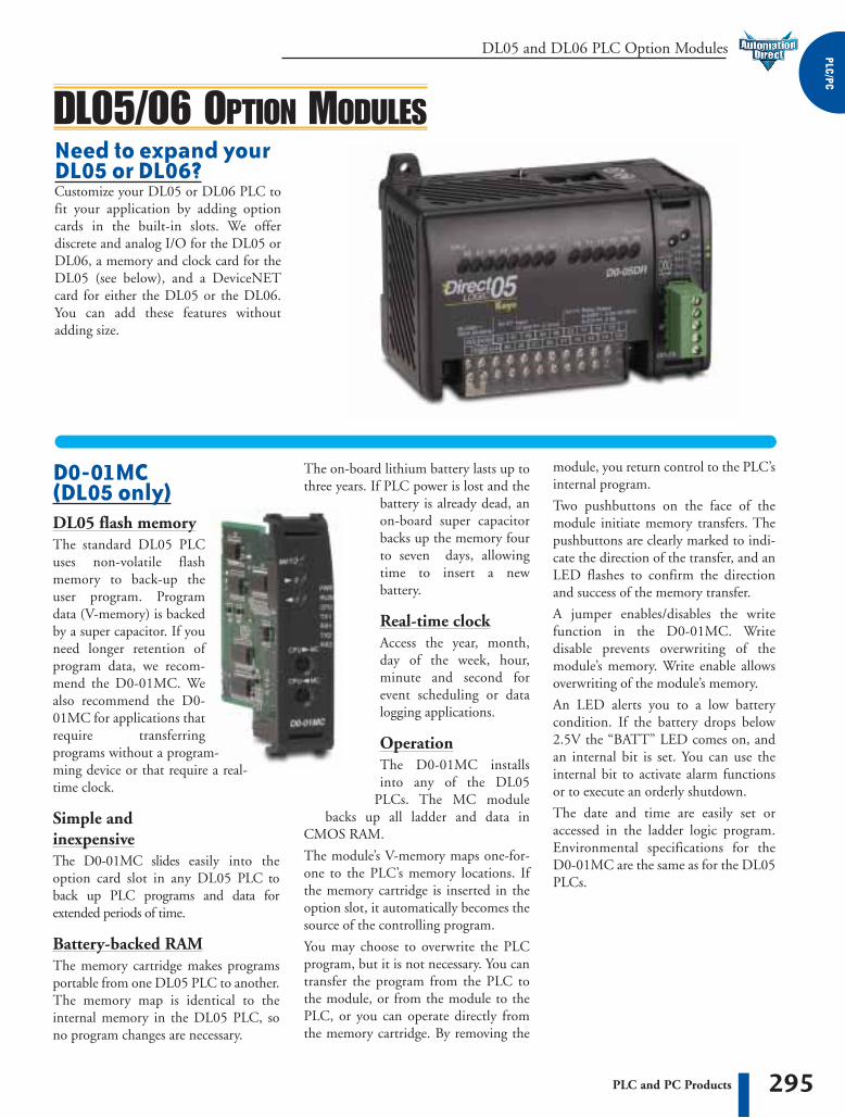
Need to expand yourDL05 or DL06?Customize your DL05 or DL06 PLC tofit your application by adding optioncards in the built-in slots. We offerdiscrete and analog I/O for the DL05 orDL06, a memory and clock card for theDL05 (see below), and a DeviceNETcard for either the DL05 or the DL06.You can add these features withoutadding size.
The on-board lithium battery lasts up tothree years. If PLC power is lost and the
battery is already dead, anon-board super capacitorbacks up the memory fourto seven days, allowingtime to insert a newbattery.
Real-time clockAccess the year, month,day of the week, hour,minute and second forevent scheduling or datalogging applications.
OperationThe D0-01MC installsinto any of the DL05
PLCs. The MC modulebacks up all ladder and data in
CMOS RAM.
The module’s V-memory maps one-for-one to the PLC’s memory locations. Ifthe memory cartridge is inserted in theoption slot, it automatically becomes thesource of the controlling program.
You may choose to overwrite the PLCprogram, but it is not necessary. You cantransfer the program from the PLC tothe module, or from the module to thePLC, or you can operate directly fromthe memory cartridge. By removing the
D0-01MC (DL05 only)DL05 flash memoryThe standard DL05 PLCuses non-volatile flashmemory to back-up theuser program. Programdata (V-memory) is backedby a super capacitor. If youneed longer retention ofprogram data, we recom-mend the D0-01MC. Wealso recommend the D0-01MC for applications thatrequire transferringprograms without a program-ming device or that require a real-time clock.
Simple and inexpensiveThe D0-01MC slides easily into theoption card slot in any DL05 PLC toback up PLC programs and data forextended periods of time.
Battery-backed RAMThe memory cartridge makes programsportable from one DL05 PLC to another.The memory map is identical to theinternal memory in the DL05 PLC, sono program changes are necessary.
DL05/06 OPTION MODULES
module, you return control to the PLC’sinternal program.
Two pushbuttons on the face of themodule initiate memory transfers. Thepushbuttons are clearly marked to indi-cate the direction of the transfer, and anLED flashes to confirm the directionand success of the memory transfer.
A jumper enables/disables the writefunction in the D0-01MC. Writedisable prevents overwriting of themodule’s memory. Write enable allowsoverwriting of the module’s memory.
An LED alerts you to a low batterycondition. If the battery drops below2.5V the “BATT” LED comes on, andan internal bit is set. You can use theinternal bit to activate alarm functionsor to execute an orderly shutdown.
The date and time are easily set oraccessed in the ladder logic program.Environmental specifications for theD0-01MC are the same as for the DL05PLCs.

DL05 and DL06 PLC Option Modules1
-8
00
-6
33
-0
40
5
296 PLC and PC Products
D0-DEVNETS The D0-DEVNETS option card trans-forms any DL05 or DL06 into a smartdevice node on your DeviceNetcontroller network. Now you don’t haveto turn to a more expensive PLC to getDeviceNet capability.
DeviceNet is a low-cost control bus usedto connect field devices to PLCs andPCs. DeviceNet is designed to reduce theneed for hard-wiring while providingdevice-level diagnostics. This industrialprotocol links up to 64 nodes on a singlenetwork.
The D0-DEVNETS slave module slidesinto the option card slot of any DL05 orDL06 PLC. The module collects andreports all discrete I/O data to aDeviceNet master.
The D0-DEVNETS module has aremovable connector that makes thefour-wire connection easy to implementand maintain. The DeviceNet moduleincorporates advanced diagnostics notcommonly found on traditional indus-trial networks. This module has the quickresponse time and high dependabilityexpected from any DeviceNet device.
Trun
k Le
ngth
Bits
pers
ec
Bran
chLe
ngth
Devi
ces
Feet Meters Feet Meters328ft 100m 500Kbps 20ft 6m 64
820ft 250m 250Kbps 20ft 6m 64
1,640ft 500m 125Kbps 20ft 6m 64
Other DeviceNet specifications, compatible products, and latestDeviceNet information are made available through:Open DeviceNet Vendor AssociationPhone: (954) 340-5412 Fax: (954) 340-5413Internet Address: http://www.odva.orge-mail: [email protected], Inc.20423 State Road 7Boca Raton, FL 33498
DL05/06 SPECIALTY OPTION MODULES
Removable connector
General Specifications
DeviceNet CompatibilityMaximum FIeld Devices per Bus
Communication to Field Devices
Predefined Group 2 Master/Slave communications
64 (see table below)
Standard 4-wire shielded cable to cabinet connector, molded 4-wire cable @ up to 500Kbps to field devices
Module ConnectorOperating TemperatureStorage TemperatureRelative HumidityEnvironmental AirVibrationShock
Noise Immunity
5-position removable terminal (European style)
0 to 55°C (32 to 131° F)
20 to 70°C (-4 to 158° F)
5 to 95% (non-condensing)
No corrosive gases permitted
MIL STD 810C 514.2
MIL STD 810C 516.2
Impulse noise 1�s, 1000V FCC class A RFI(144Mhz, 430Mhz 10W, 10cm)

297PLC and PC Products
DL05 and DL06 PLC Option Modules PLC/PC
DL05/06 I/O OPTION MODULESD0-10ND310-point DC input module
Operating Voltage Range 12-24VDC
Input Voltage Range 10.8-26.4VDC
Peak Voltage 30.0VDC
Maximum Input CurrentInput Impedance 2.8K� @ 12-24VDC
Input Current Typical:4.0mA @ 12VDC8.5mA @ 24VDC
Off to on Response
On Voltage Level > 10.0 VDC
Off Voltage Level < 2.0 VDC
2-8ms, Typ. 4ms
On to off Response 2-8ms, Typ. 4ms
Status Indicators Module activity: one green LED
Commons 2 non-isolated
Number of Inputs 10 (sink/source)
FuseBase Power Required (5V)
No fuse
Typical. 35mA (all pts. on)
D0-10ND3 Input Specifications
11mA @ 26.4VDC
Minimum ON CurrentMinimum OFF Current
3.5mA
0.5mA
Derating chart
Equivalent input circuit
DL05 and DL06 PLC Option Modules1
-8
00
-6
33
-0
40
5
298 PLC and PC Products
DL05/06 I/O OPTION MODULES
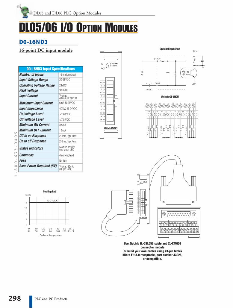
Use ZipLink ZL-CBL056 cable and ZL-CM056connector module
or build your own cables using 24-pin MolexMicro Fit 3.0 receptacle, part number 43025,
or compatible.
D0-16ND316-point DC input module
Operating Voltage Range 24VDC
Input Voltage Range 20-28VDC
Peak Voltage 30.0VDC
Maximum Input Current 6mA @ 28VDC
Input Impedance 4.7K� @ 24VDC
Input Current Typical:4.0mA @ 24VDC
Off to on Response
On Voltage Level > 19.0 VDC
Off Voltage Level < 7.0 VDC
2-8ms, Typ. 4ms
On to off Response 2-8ms, Typ. 4ms
Status Indicators Module activity: one green LED
Commons 4 non-isolated
Number of Inputs 16 (sink/source)
FuseBase Power Required (5V)
No fuse
Typical. 35mA (all pts. on)
D0-16ND3 Input Specifications
Minimum ON CurrentMinimum OFF Current
3.5mA
1.5mA
Equivalent input circuit
Wiring for ZL-056CM
Derating chart

299PLC and PC Products
DL05 and DL06 PLC Option Modules PLC/PC
DL05/06 I/O OPTION MODULESD0-10TD1 10-point DC output module
D0-10TD1 Output Specifications
Operating Voltage Range 6-27VDC
Output Voltage Range 5-30VDC
Peak Voltage 50.0VDC
Maximum Output Current 0.3A/point, 1.5A/common
Minimum Output Current 0.5mA
Maximum Leakage Current 15�A @ 30.0VDC
Off to On Response
On Voltage Drop 0.5VDC @ 0.3A
Maximum Inrush Current 1A for 10ms
< 10�s
On to Off Response < 60�s
Status Indicators Module activity: one green LED
Commons 2 non-isolated(5 points/common)
Number of Outputs 10 (sinking)
FuseExternal DC PowerRequiredBase Power Required (5V)
No fuse
20-28VDC max200mA (all pts. on)
Max. 150mA (all pts. on)
Derating chart
Equivalent output circuit

DL05 and DL06 PLC Option Modules1
-8
00
-6
33
-0
40
5
300 PLC and PC Products
DL05/06 I/O OPTION MODULESD0-16TD116-point DC output module
D0-16TD1 Output Specifications
Operating Voltage Range 6-27VDC
Output Voltage Range 5-30VDC
Peak Voltage 50.0VDC
Maximum Output Current 0.1A/point, 0.8A/common
Minimum Output Current 0.5mA
Maximum Leakage Current 15�A @ 30.0VDC
Off to On Response
On Voltage Drop 0.5VDC @ 0.1A
Maximum Inrush Current 1A for 10ms
< 0.5ms
On to Off Response < 0.5ms
Status Indicators Module activity: one green LED
Commons 2 isolated(8 points/common)
Number of Outputs 16 (sinking)
FuseExternal DC PowerRequired
Base Power Required (5V)
No fuse
20-28VDC max 70mA(all pts. on)
Max. 200mA (all pts. on)
Use ZipLink ZL-CBL056 cable and ZL-CM056connector module
or build your own cables using 24-pin MolexMicro Fit 3.0 receptacle, part number 43025,
or compatible.
Equivalent output circuit
Wiring for ZL-056CM
Derating chart

301PLC and PC Products
DL05 and DL06 PLC Option Modules PLC/PC
D0-10TD2 10-point DC output module
DL05/06 I/O OPTION MODULES
Equivalent output circuit
Derating chart
D0-10TD2 Output Specifications
Operating Voltage Range 12-24VDC
Output Voltage Range 10.8-26.4VDC
Peak Voltage 50.0VDC
Maximum Output Current 0.3A/point, 1.5A/common
Minimum Output Current 0.5mA
Maximum Leakage Current 1.5�A @ 26.4VDC
Off to On Response
On Voltage Drop 1.0VDC @ 0.3A
Maximum Inrush Current 1A for 10ms
< 10�s
On to Off Response < 60�s
Status Indicators Module activity: one green LED
Commons 2 non-isolated(5 points/common)
Number of Outputs 10 (sourcing)
FuseBase Power Required (5V)
No fuse
Max. 150mA (all pts. on)

DL05 and DL06 PLC Option Modules1
-8
00
-6
33
-0
40
5
302 PLC and PC Products
DL05/06 I/O OPTION MODULESD0-16TD2 16-point DC output module
D0-16TD2 Output Specifications
Operating Voltage Range 12-24VDC
Output Voltage Range 10.8-26.4VDC
Peak Voltage 50.0VDC
Maximum Output Current 0.1A/point, 0.8A/common
Minimum Output Current 0.5mA
Maximum Leakage Current 1.5�A @ 26.4VDC
Off to On Response
On Voltage Drop 1.0VDC @ 0.1A
Maximum Inrush Current 1A for 10ms
< 0.5ms
On to Off Response < 0.5ms
Status Indicators Module activity: one green LED
Commons 2 non-isolated(8 points/common)
Number of Outputs 16 (sourcing)
FuseBase Power Required (5V)
No fuse
Max. 200mA (all pts. on)
Use ZipLink ZL-CBL056 cable and ZL-CM056connector module
or build your own cables using 24-pin MolexMicro Fit 3.0 receptacle, part number 43025,
or compatible.
Equivalent output circuit
Wiring for ZL-056CM
Derating chart
303PLC and PC Products
DL05 and DL06 PLC Option Modules PLC/PC
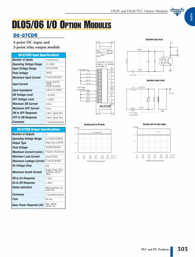
D0-07CDR 4-point DC input and3-point relay output module
DL05/06 I/O OPTION MODULES
D0-07CDR Output Specifications
Operating Voltage Range 6-27VDC/6-240VAC
Output Type Relay, form A (SPST)
Peak Voltage 30.0VDC/264VAC
Maximum Current (resist.) 1A/point, 4A/common
Minimum Load Current 5mA @ 5VDC
Maximum Leakage Current 0.1mA @ 264VAC
Off to On Response
On Voltage Drop N/A
Maximum Inrush CurrentOutput: 3A for 10msCommon: 10A for10ms
< 15ms
On to Off Response < 10ms
Status Indicators Module activity: onegreen LED
Commons 1 (3 points/common)
Number of Outputs 3
Fuse
Base Power Required (5V)
No fuse
Max. 200mA (all pts. on)
D0-07CDR Input Specifications
Operating Voltage Range 12-24VDC
Input Voltage Range 10.8-26.4VDC
Peak Voltage 30VDC
Maximum Input Current 11mA @ 26.4VDC
Input CurrentTypical: 4mA @12VDC8.5mA @ 24VDC
Input Impedance 2.8K @ 12-24VDC
Minimum ON Current
ON Voltage Level > 10.0VDC
OFF Voltage Level < 2.0VDC
3.5ms
Maximum OFF Current 0.5ms
ON to OFF Response 2-8ms, Typical 4ms
OFF to ON Response 2-8ms, Typical 4ms
Number of Inputs 4 (sink/source)
Commons 1 (4 points/common)
Equivalent input circuit
Equivalent output circuit
Derating chart for DC inputs Derating chart for relay outputs

DL05 and DL06 PLC Option Modules1
-8
00
-6
33
-0
40
5
304 PLC and PC Products
D0-08TR 8-point relay output module
DL05/06 I/O OPTION MODULES
D0-08TR Output Specifications
Operating Voltage Range 6-27VDC/6-240VAC
Output Type Relay, form A (SPST)
Peak Voltage 30.0VDC/264VAC
Maximum Current (resist.) 1A/point, 4A/common
Minimum Load Current 0.5mA
Maximum Leakage Current 0.1mA @ 264VAC
Off to On Response
On Voltage Drop N/A
Maximum Inrush Current Output: 3A for 10msCommon: 10A for10ms
< 15ms
On to Off Response < 10ms
Status Indicators Module activity: onegreen LED
Commons 2 isolated (4 points/common)
Number of Outputs 8
Fuse
Base Power Required (5V)
No fuse
Max. 280mA (all pts. on)
Equivalent output circuit
Derating chart

305PLC and PC Products
DL05 and DL06 PLC Option Modules PLC/PC
D0-08CDD1 4-point DC input and4-point DC output module
DL05/06 I/O OPTION MODULES
D0-08CDD1 Output Specifications
Operating Voltage range 6-27VDC
Output voltage Range 5-30VDC
Peak Voltage 50.0VDC
Maximum Output Current 0.3A/point, 1.2A/common
Minimum Output Current 0.5mA
Maximum Leakage Current 1.5�A @ 30.0VDC
Off to On Response
On Voltage Drop 0.5VDC @ 0.3A
Maximum Inrush Current 1A for 10ms
< 10�s
On to Off Response < 60�s
Status Indicators Module activity: onegreen LED
Commons 2 non-isolated (2 points/common)
Number of Outputs 4 (sinking)
FuseBase Power Required (5V)
No fuse
Max. 200mA (all pts. on)
D0-08CDD1 Input Specifications
Operating Voltage Range 10.8-26.4VDC
Input Voltage Range 12-24VDC
Peak Voltage 30VDC
Maximum Input Current 11mA @ 26.4VDC
Input CurrentTypical: 4mA @ 2VDC8.5mA @ 24VDC
Input Impedance 2.8K @ 12-24VDC
Minimum ON Current
ON Voltage Level > 10.0VDC
OFF Voltage Level < 2.0VDC
3.5mA
Maximum OFF Current 0.5mA
ON to OFF Response 2-8ms, typical 4ms
OFF to ON Response 2-8ms, typical 4ms
Number of Inputs 4 (sink/source)
Commons 2 non-isolated (2 points/common)
Equivalent output circuit
Equivalent input circuit
Derating chart for DC inputs Derating chart for DC outputs
External DC PowerRequired (24V)
20-28VDC, max.80mA (all pts. on)

DL05 and DL06 PLC Option Modules1
-8
00
-6
33
-0
40
5
306 PLC and PC Products
DL05/06 OPTION MODULESF0-04AD-1 4-point analog input module
Input Specifications
Input Range0 to20mA or 4 to 20mA (jumper selectable)
Resolution 12 bit (1 in 4096)
Step Response25.0mS (typ.) to 95% of full step change
Crosstalk 1/2 count max (-80db)*
Active Low-pass Filtering -3dB at 40Hz (-12dB per octave)
Input Impedance 125� �0.1%, 1/8 watt
Input Stability
Absolute Max Ratings -30mA to +30mA, current input
Linearity Error (end to end) �2 counts
�1 count*
Full-scale Calibration Error �10 counts max. @ 20mA*
Offset Calibration Error �5 counts max. @ 4mA*
Max Inaccuracy�0.4% at 25�C (77�F)�0.85% at 0 to 60�C(32 to 140�F)
Accuracy vs. Temperature �100 ppm/�C typical
Number of Channels 4, single ended (one common)
Converter Type
Recommended Fuse
Successive approximation
0.032A, series 217fast-acting, current inputs

307PLC and PC Products
DL05 and DL06 PLC Option Modules PLC/PC
F0-2AD2DA-2 2-point analog input and2-point analog output module
* One count in the specification table is equal to oneleast significant bit of the analog data value (1 in 4096)
DL05/06 OPTION MODULES
Output Specifications
Output Range0 to5VDC or 0 to 10VDC (jumper selectable)
Resolution 12 bit (1 in 4096)
Conversion Settling Time 50�S for full scale change
Crosstalk 1/2 count max (-80db)*
Peak Output Voltage �15VDC (power supply limited)
Offset Error 0.1% of range
Output Stability
Gain Error 0.4% of range
Linearity Error (end to end) �1 counts (0.075% of full scale) max*
�2 counts*
Load Impedance 2K� max
Load Capacitance 0.01�F max
Accurracy vs. Temperature �50 ppm/�C typical
Number of Channels 2, single ended (one common)
Input Specifications
Input Range0 to 5VDC or 0 to 10VDC (jumper selectable)
Resolution 12 bit (1 in 4096)
Step Response 10.0mS to 95% of full step change
Crosstalk 1/2 count max (-80db)*
Active Low-pass Filtering -3dB at 300Hz (-12dB per octave)
Input Impedance �20K�
Input Stability
Absolute Max Ratings �15V
Linearity Error (end to end) �2 counts (0.025% of full scale) max*
�1 count*
Gain Error �6 counts max*
Offset Error �2 counts max*
Max Inaccuracy�0.3% at 25�C (77�F)�0.6% at 0 to 60�-C(32 to 140�F)
Accurracy vs. Temperature �100 ppm/�C typical
Number of Channels 2, single ended (one common)

DL05 and DL06 PLC Option Modules1
-8
00
-6
33
-0
40
5
308 PLC and PC Products
F0-4AD2DA-1 4-point analog input and2-point analog output module
DL05/06 OPTION MODULES
Input Specifications
Input Range0 to20mA or 4 to 20mA (jumper selectable)
Resolution 12 bit (1 in 4096)
Step Response25.0mS (typ.) to 95% of full step change
Crosstalk 1/2 count max (-80db)*
Active Low-pass Filtering -3dB at 40Hz (-12dB per octave)
Input Impedance 125� �0.1%, 1/8 watt
Input Stability
Absolute Max Ratings -30mA to +30mA, current input
Linearity Error (end to end) �2 counts
�1 count*
Full-scale Calibration Error �10 counts max. @ 20mA*
Offset Calibration Error �5 counts max. @ 0mA*
Max Inaccuracy�0.4% at 25�C (77�F)�0.85% at 0 to 60�C(32 to 140�F)
Accurracy vs. Temperature �100 ppm/�C typical
Number of Channels 4, single ended (one common)
Output Specifications
Output Range0 to20mA or 4 to 20mA (jumper selectable)
Resolution 12 bit (1 in 4096)
Conversion Settling Time 400�s max. for full scale change
Output Type Current sourcing
Max. Loop Voltage 30VDC
Offset Calibration Error
�10 counts max.. @300� load�8 counts max.. @250� load�6 counts max.. @125� load
Max.Full- scale Inaccuracy(all errors included)
Full-scale Calibration Error
�26 counts max. @300� load�18 counts max.. @250� load�12 counts max.. @125� load
Linearity Error (end to end)�2 counts (0.050% of full scale)max.*
300� load 0.4%. @ 60� C250� load 0.3%. @ 60� C125� load 0.2%. @ 60� C
Load/loop Power Supply 0-300� /18-30VDC
Number of Channels 2, single ended (one common)
Converter Type
Recommended Fuse
Successive approximation
0.032A, series 217fast-acting, current inputs
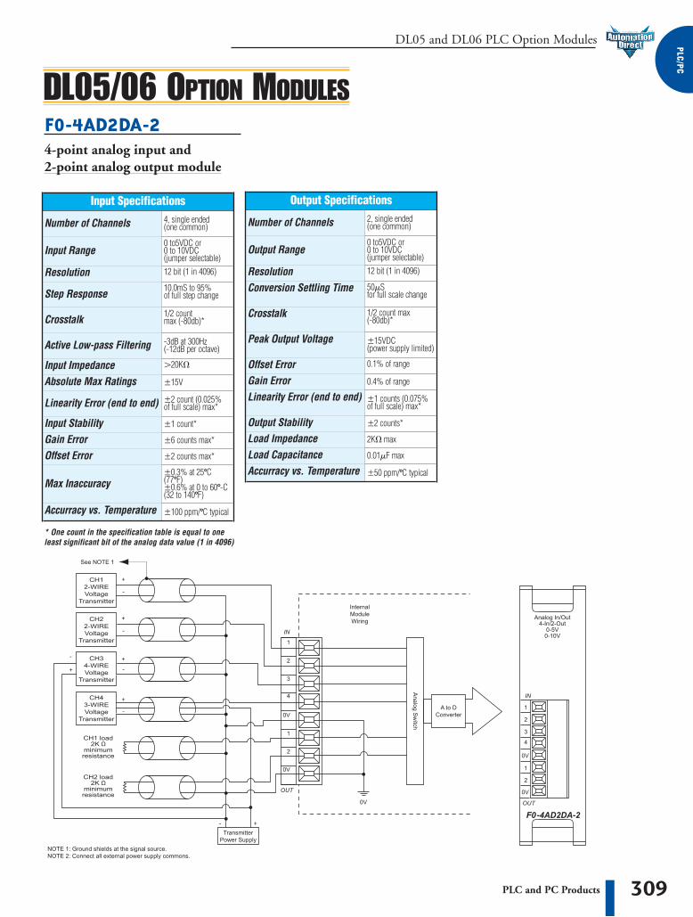
309PLC and PC Products
DL05 and DL06 PLC Option Modules PLC/PC
F0-4AD2DA-2 4-point analog input and2-point analog output module
Output Specifications
Output Range0 to5VDC or 0 to 10VDC (jumper selectable)
Resolution 12 bit (1 in 4096)
Conversion Settling Time 50�S for full scale change
Crosstalk 1/2 count max (-80db)*
Peak Output Voltage �15VDC (power supply limited)
Offset Error 0.1% of range
Output Stability
Gain Error 0.4% of range
Linearity Error (end to end) �1 counts (0.075% of full scale) max*
�2 counts*
Load Impedance 2K� max
Load Capacitance 0.01�F max
Accurracy vs. Temperature �50 ppm/�C typical
Input Specifications
Input Range0 to5VDC or 0 to 10VDC (jumper selectable)
Resolution 12 bit (1 in 4096)
Step Response 10.0mS to 95% of full step change
Crosstalk 1/2 count max (-80db)*
Active Low-pass Filtering -3dB at 300Hz (-12dB per octave)
Input Impedance �20K�
Input Stability
Absolute Max Ratings �15V
Linearity Error (end to end) �2 count (0.025% of full scale) max*
�1 count*
Gain Error �6 counts max*
Offset Error �2 counts max*
Max Inaccuracy�0.3% at 25�C (77�F)�0.6% at 0 to 60�-C(32 to 140�F)
Accurracy vs. Temperature �100 ppm/�C typical
* One count in the specification table is equal to oneleast significant bit of the analog data value (1 in 4096)
Number of Channels 4, single ended (one common) Number of Channels 2, single ended
(one common)
DL05/06 OPTION MODULES
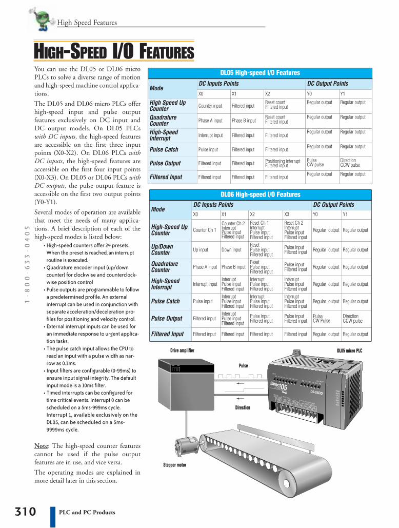
You can use the DL05 or DL06 microPLCs to solve a diverse range of motionand high-speed machine control applica-tions.
The DL05 and DL06 micro PLCs offerhigh-speed input and pulse outputfeatures exclusively on DC input andDC output models. On DL05 PLCswith DC inputs, the high-speed featuresare accessible on the first three inputpoints (X0-X2). On DL06 PLCs withDC inputs, the high-speed features areaccessible on the first four input points(X0-X3). On DL05 or DL06 PLCs withDC outputs, the pulse output feature isaccessible on the first two output points(Y0-Y1).
Several modes of operation are availablethat meet the needs of many applica-tions. A brief description of each of thehigh-speed modes is listed below:
• High-speed counters offer 24 presets.When the preset is reached, an interruptroutine is executed.
• Quadrature encoder input (up/downcounter) for clockwise and counterclock-wise position control
• Pulse outputs are programmable to followa predetermined profile. An externalinterrupt can be used in conjunction withseparate acceleration/deceleration pro-files for positioning and velocity control.
• External interrupt inputs can be used foran immediate response to urgent applica-tion tasks.
• The pulse catch input allows the CPU toread an input with a pulse width as nar-row as 0.1ms.
• Input filters are configurable (0-99ms) toensure input signal integrity. The defaultinput mode is a 10ms filter.
• Timed interrupts can be configured fortime critical events. Interrupt 0 can bescheduled on a 5ms-999ms cycle.Interrupt 1, available exclusively on theDL05, can be scheduled on a 5ms-9999ms cycle.
Note: The high-speed counter featurescannot be used if the pulse outputfeatures are in use, and vice versa.
The operating modes are explained inmore detail later in this section.
Stepper motor
Drive amplifier
Pulse
Direction
DL05 micro PLC
High Speed Features1
-8
00
-6
33
-0
40
5
310 PLC and PC Products
DL05 High-speed I/O FeaturesDC Inputs Points
ModeX0 X1 X2 Y0 Y1
High Speed UpCounter Counter input Filtered input
Reset countFiltered input
Regular output Regular output
QuadratureCounter Phase A input Phase B input
Reset countFiltered input
Regular output Regular output
High-SpeedInterrupt Interrupt input Filtered input Filtered input
Regular output Regular output
Pulse Catch Pulse input Filtered input Filtered input Regular output Regular output
Pulse Output Filtered input Filtered input Positioning interruptFiltered input
Pulse CW pulse
Direction CCW pulse
Filtered Input Filtered input Filtered input Filtered input Regular output Regular output
DC Output Points
HIGH-SPEED I/O FEATURES
DL06 High-speed I/O FeaturesDC Inputs Points
ModeX0 X1 X2 Y0 Y1
High-Speed UpCounter Counter Ch 1
Counter Ch 2Interrupt Pulse inputFiltered input
Reset Ch 1Interrupt Pulse inputFiltered input
Regular output Regular output
QuadratureCounter Phase A input Phase B input
Reset Pulse input Filtered input
Regular output Regular output
High-SpeedInterrupt Interrupt input
Interrupt Pulse inputFiltered input
Interrupt Pulse input Filtered input
Regular output Regular output
Pulse Catch Pulse inputInterrupt Pulse inputFiltered input
Interrupt Pulse input Filtered input
Regular output Regular output
Pulse Output Filtered inputInterrupt Pulse inputFiltered input
Pulse input Filtered input
Pulse CW Pulse
Direction CCW pulse
Filtered Input Filtered input Filtered input Filtered input Regular output Regular output
DC Output PointsX3
Reset Ch 2Interrupt Pulse input Filtered input
Pulse input Filtered input
Interrupt Pulse input Filtered inputInterrupt Pulse input Filtered input
Pulse input Filtered input
Filtered input
Up/DownCounter
Reset Pulse inputFiltered input
Up input Regular output Regular outputPulse input Filtered inputDown input
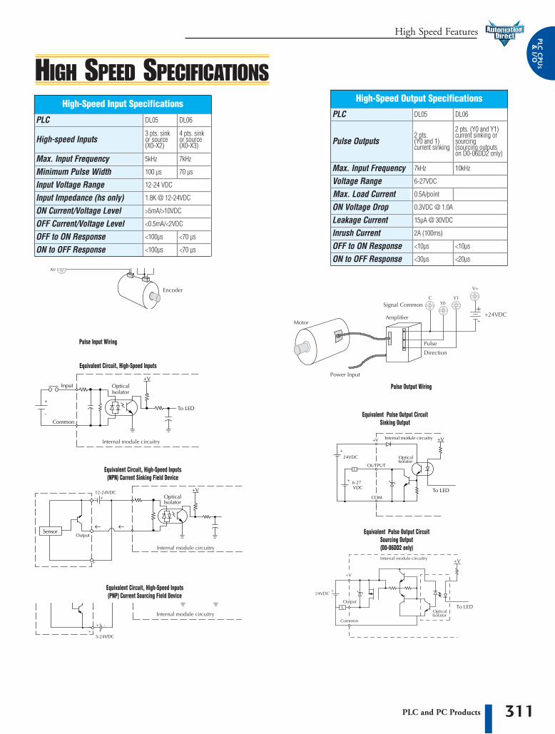
311PLC and PC Products
High Speed Features PPLLCC CC
PPUUSS
&&II//OO
HIGH SPEED SPECIFICATIONSHigh-Speed Input Specifications
100 µs
Input Voltage Range 12-24 VDC
Input Impedance (hs only) 1.8K @ 12-24VDC
ON Current/Voltage Level >5mA/>10VDC
OFF Current/Voltage Level <0.5mA/<2VDC
OFF to ON Response <100µs
ON to OFF Response <100µs
High-speed Inputs 3 pts. sinkor source(X0-X2)
High-Speed Output Specifications
Pulse Outputs2 pts. (Y0 and 1)current sinking
Voltage Range 6-27VDC
Max. Load CurrentON Voltage Drop 0.3VDC @ 1.0A
Leakage Current 15µA @ 30VDC
Inrush Current 2A (100ms)
OFF to ON Response <10µs
ON to OFF Response <30µs
0.5A/point
Equivalent Circuit, High-Speed Inputs
Equivalent Circuit, High-Speed Inputs(NPN) Current Sinking Field Device
Equivalent Circuit, High-Speed Inputs(PNP) Current Sourcing Field Device
Equivalent Pulse Output CircuitSinking Output
Equivalent Pulse Output CircuitSourcing Output(D0-06DD2 only)
Pulse Output Wiring
Pulse Input Wiring
Minimum Pulse WidthMax. Input Frequency 5kHz 7kHz
DL05 DL06
10kHz7kHz
PLC
70 µs
<70 µs
<70 µs
4 pts. sinkor source(X0-X3)
PLC DL05 DL06
Max. Input Frequency
2 pts. (Y0 and Y1)current sinking orsourcing (sourcing outputs on D0-06DD2 only)
<10µs
<20µs
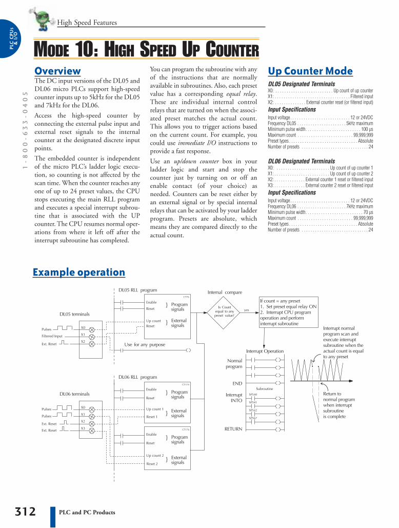
High Speed Features1
-8
00
-6
33
-0
40
5
312 PLC and PC Products
PPLLCC
CCPPUU
SS&&
II//OO
Up Counter ModeDL05 Designated TerminalsX0: . . . . . . . . . . . . . . . . . . . . . . . . . . Up count of up counterX1: . . . . . . . . . . . . . . . . . . . . . . . . . . . . . . . . . . Filtered inputX2: . . . . . . . . . . . . . . External counter reset (or filtered input) Input SpecificationsInput voltage. . . . . . . . . . . . . . . . . . . . . . . . . . . 12 or 24VDCFrequency DL05 . . . . . . . . . . . . . . . . . . . . . . 5kHz maximumMinimum pulse width. . . . . . . . . . . . . . . . . . . . . . . . . 100 µsMaximum count . . . . . . . . . . . . . . . . . . . . . . . . . 99,999,999Preset types . . . . . . . . . . . . . . . . . . . . . . . . . . . . . . . AbsoluteNumber of presets . . . . . . . . . . . . . . . . . . . . . . . . . . . . . . 24
DL06 Designated TerminalsX0: . . . . . . . . . . . . . . . . . . . . . . . . Up count of up counter 1X1: . . . . . . . . . . . . . . . . . . . . . . . . . Up count of up counter 2X2: . . . . . . . . . . . . . . External counter 1 reset or filtered inputX3: . . . . . . . . . . . . . . External counter 2 reset or filtered inputInput SpecificationsInput voltage. . . . . . . . . . . . . . . . . . . . . . . . . . . 12 or 24VDCFrequency DL06 . . . . . . . . . . . . . . . . . . . . . . 7kHz maximumMinimum pulse width. . . . . . . . . . . . . . . . . . . . . . . . . . 70 µsMaximum count . . . . . . . . . . . . . . . . . . . . . . . . . 99,999,999Preset types . . . . . . . . . . . . . . . . . . . . . . . . . . . . . . . AbsoluteNumber of presets . . . . . . . . . . . . . . . . . . . . . . . . . . . . . . 24
OverviewThe DC input versions of the DL05 andDL06 micro PLCs support high-speedcounter inputs up to 5kHz for the DL05and 7kHz for the DL06.
Access the high-speed counter byconnecting the external pulse input andexternal reset signals to the internalcounter at the designated discrete inputpoints.
The embedded counter is independentof the micro PLC’s ladder logic execu-tion, so counting is not affected by thescan time. When the counter reaches anyone of up to 24 preset values, the CPUstops executing the main RLL programand executes a special interrupt subrou-tine that is associated with the UPcounter. The CPU resumes normal oper-ations from where it left off after theinterrupt subroutine has completed.
You can program the subroutine with anyof the instructions that are normallyavailable in subroutines. Also, each presetvalue has a corresponding equal relay.These are individual internal controlrelays that are turned on when the associ-ated preset matches the actual count.This allows you to trigger actions basedon the current count. For example, youcould use immediate I/O instructions toprovide a fast response.
Use an up/down counter box in yourladder logic and start and stop thecounter just by turning on or off anenable contact (of your choice) asneeded. Counters can be reset either byan external signal or by special internalrelays that can be activated by your ladderprogram. Presets are absolute, whichmeans they are compared directly to theactual count.r
Example operation
MODE 10: HIGH SPEED UP COUNTER
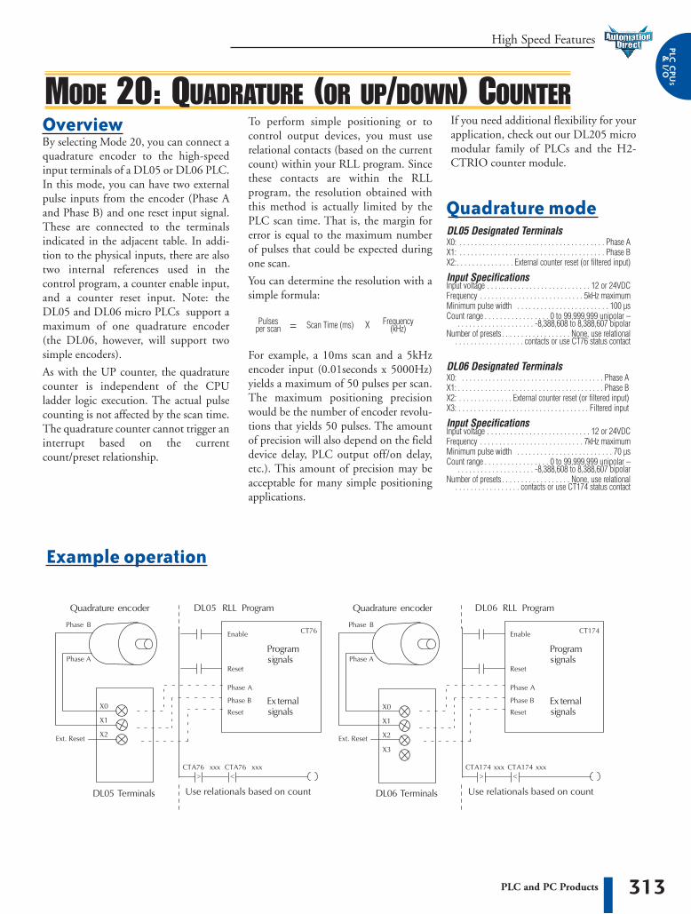
313PLC and PC Products
High Speed Features PPLLCC CC
PPUUSS
&&II//OO
OverviewBy selecting Mode 20, you can connect aquadrature encoder to the high-speedinput terminals of a DL05 or DL06 PLC.In this mode, you can have two externalpulse inputs from the encoder (Phase Aand Phase B) and one reset input signal.These are connected to the terminalsindicated in the adjacent table. In addi-tion to the physical inputs, there are alsotwo internal references used in thecontrol program, a counter enable input,and a counter reset input. Note: theDL05 and DL06 micro PLCs support amaximum of one quadrature encoder(the DL06, however, will support twosimple encoders).
As with the UP counter, the quadraturecounter is independent of the CPUladder logic execution. The actual pulsecounting is not affected by the scan time.The quadrature counter cannot trigger aninterrupt based on the currentcount/preset relationship.
To perform simple positioning or tocontrol output devices, you must userelational contacts (based on the currentcount) within your RLL program. Sincethese contacts are within the RLLprogram, the resolution obtained withthis method is actually limited by thePLC scan time. That is, the margin forerror is equal to the maximum numberof pulses that could be expected duringone scan.
You can determine the resolution with asimple formula:
For example, a 10ms scan and a 5kHzencoder input (0.01seconds x 5000Hz)yields a maximum of 50 pulses per scan.The maximum positioning precisionwould be the number of encoder revolu-tions that yields 50 pulses. The amountof precision will also depend on the fielddevice delay, PLC output off/on delay,etc.). This amount of precision may beacceptable for many simple positioningapplications.
Example operation
If you need additional flexibility for yourapplication, check out our DL205 micromodular family of PLCs and the H2-CTRIO counter module.
MODE 20: QUADRATURE (OR UP/DOWN) COUNTER
Quadrature modeDL05 Designated TerminalsX0: . . . . . . . . . . . . . . . . . . . . . . . . . . . . . . . . . . . . . . Phase AX1: . . . . . . . . . . . . . . . . . . . . . . . . . . . . . . . . . . . . . . Phase BX2:. . . . . . . . . . . . . . . External counter reset (or filtered input)
Input SpecificationsInput voltage . . . . . . . . . . . . . . . . . . . . . . . . . . . 12 or 24VDCFrequency . . . . . . . . . . . . . . . . . . . . . . . . . . . 5kHz maximumMinimum pulse width . . . . . . . . . . . . . . . . . . . . . . . . 100 µsCount range . . . . . . . . . . . . . . . . . 0 to 99,999,999 unipolar –
. . . . . . . . . . . . . . . . . . . . -8,388,608 to 8,388,607 bipolarNumber of presets . . . . . . . . . . . . . . . . . . None, use relational
. . . . . . . . . . . . . . . . . . contacts or use CT76 status contact
DL06 Designated TerminalsX0: . . . . . . . . . . . . . . . . . . . . . . . . . . . . . . . . . . . . . Phase AX1: . . . . . . . . . . . . . . . . . . . . . . . . . . . . . . . . . . . . . . Phase BX2: . . . . . . . . . . . . . . External counter reset (or filtered input)X3: . . . . . . . . . . . . . . . . . . . . . . . . . . . . . . . . . . Filtered input
Input SpecificationsInput voltage . . . . . . . . . . . . . . . . . . . . . . . . . . . 12 or 24VDCFrequency . . . . . . . . . . . . . . . . . . . . . . . . . . . 7kHz maximumMinimum pulse width . . . . . . . . . . . . . . . . . . . . . . . . . 70 µsCount range . . . . . . . . . . . . . . . . . 0 to 99,999,999 unipolar –
. . . . . . . . . . . . . . . . . . . . -8,388,608 to 8,388,607 bipolarNumber of presets . . . . . . . . . . . . . . . . . . None, use relational
. . . . . . . . . . . . . . . . . contacts or use CT174 status contact
Pulsesper scan = Scan Time (ms) X Frequency
(kHz)
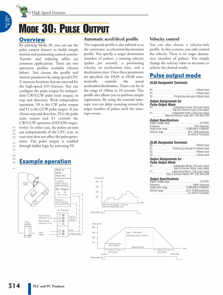
High Speed Features1
-8
00
-6
33
-0
40
5
314 PLC and PC Products
PPLLCC
CCPPUU
SS&&
II//OO
OverviewBy selecting Mode 30, you can use thepulse output feature to build simplemotion and positioning control systems.Transfer and indexing tables arecommon applications. There are twooperation profiles available (shownbelow). You choose the profile andmotion parameters by using special CPUV-memory locations that are reserved forthe high-speed I/O features. You canconfigure the pulse output for indepen-dent CW/CCW pulse train output, orstep and direction. With independentoperation, Y0 is the CW pulse outputand Y1 is the CCW pulse output. If youchoose step and direction, Y0 is the pulsetrain output and Y1 controls theCW/CCW operation (OFF/ON respec-tively). In either case, the pulses are sentout independently of the CPU scan, soscan time does not affect the pulse gener-ation. The pulse output is enabledthrough ladder logic by activating Y0.
MODE 30: PULSE OUTPUTAutomatic accel/decel profile The trapezoid profile is also referred to asthe automatic acceleration/decelerationprofile. You specify a target destination(number of pulses), a starting velocity(pulses per second), a positioningvelocity, an acceleration time, and adeceleration time. Once these parametersare specified, the DL05 or DL06 auto-matically controls the actualacceleration/deceleration. Times can be inthe range of 100ms to 10 seconds. Thisprofile also allows you to perform simpleregistration. By using the external inter-rupt, you can delay counting toward thetarget number of pulses until the inter-rupt occurs.
Example operation
Velocity control You can also choose a velocity-onlyprofile. In this scenario, you only controlthe velocity. There is no target destina-tion (number of pulses). You simplychange the velocity value as necessary toachieve the desired results.
Pulse output modeDL05 Designated Terminals
X0:. . . . . . . . . . . . . . . . . . . . . . . . . . . . . . . . . . . Filtered inputX1:. . . . . . . . . . . . . . . . . . . . . . . . . . . . . . . . . . . Filtered inputX2:. . . . . . . . . . . . . . . . . Positioning interrupt or filtered input
Output Assignments for Pulse Output ModeY0: . . . . . . . . . . . . . . . . Independent mode, CW pulse output
. . . . . . . . . . . . . . . . Step and direction mode, pulse outputY1: . . . . . . . . . . . . . . . Independent mode, CCW pulse output
. . . . . . . . . . Step and direction mode, OFF=CW, ON=CCW
Output SpecificationsOutput voltage range . . . . . . . . . . . . . . . . . . . . . . . . 6-27VDCFrequency . . . . . . . . . . . . . . . . . . . . . . . . . . . 7kHz maximumTarget pulse range . . . . . . . . . . . . . . -8,388,608 to 8,388,607Velocity range . . . . . . . . . . . . . . . . . . . 40 to 7000 pulses/sec
. . . . . . . . . . . . . . . . . . . . . . . . . . . . (in units of 10 pulses)
DL06 Designated TerminalsX0:. . . . . . . . . . . . . . . . . . . . . . . . . . . . . . . . . . . Filtered inputX1: . . . . . . . . . . . . . . . Positioning interrupt (or filtered input)X2:. . . . . . . . . . . . . . . . . . . . . . . . . . . . . . . . . . . Filtered input X3:. . . . . . . . . . . . . . . . . . . . . . . . . . . . . . . . . . . Filtered inputOutput Assignments for Pulse Output ModeY0: . . . . . . . . . . . . . . . . Independent Mode, CW pulse output
. . . . . . . . . . . . . . . . . Step & Direction Mode, pulse outputY1: . . . . . . . . . . . . . . . Independent Mode, CCW pulse output
. . . . . . . . . . . Step & Direction Mode, OFF=CW, ON=CCW
Output SpecificationsOutput voltage range . . . . . . . . . . . . . . . . . . . . . . . . 6-27VDCFrequency . . . . . . . . . . . . . . . . . . . . . . . . . . 10kHz maximumTarget pulse range . . . . . . . . . . . . . . -8,388,608 to 8,388,607Velocity range . . . . . . . . . . . . . . . . . . 40 to 10,000 pulses/sec
. . . . . . . . . . . . . . . . . . . . . . . . . . . . (in units of 10 pulses)

315PLC and PC Products
High Speed Features PPLLCC CC
PPUUSS
&&II//OO
CPU scan, and then it is automaticallyset to the OFF state. Like the othermodes, the pulse catch feature operatesindependently of the CPU scan and isnot affected by scan time fluctuations. Mode 50 is not recommended for high-speed pulsecounting.
Mode 50: pulse catch input overviewBy selecting Mode 50, you can use X0 asa pulse catch input. In this configuration,the DL05 or DL06 micro PLC cancapture very fast (narrow) pulse inputsthat cannot normally be detected duringthe normal input update cycle. You candetect pulse widths as small as 0.1ms(100µS) and a pulse period greater than0.5ms (500µS). When an external pulse isencountered, X0 is set on for the next
Pulse catch modeDL05 Designated TerminalsX0: . . . . . . . . . . . . . . . . . . . . . . . . . . . . . . . Pulse catch inputX1: . . . . . . . . . . . . . . . . . . . . . . . . . . . . . . . . . . Filtered inputX2: . . . . . . . . . . . . . . . . . . . . . . . . . . . . . . . . . . Filtered input
Input SpecificationsInput voltage . . . . . . . . . . . . . . . . . . . . . . . . . . 12 or 24 VDCMinimum pulse width. . . . . . . . . . . . . . . . . . . . . . . . . 100 µsPulse period . . . . . . . . . . . . . . . . . . . . . . . . 0.5ms or greaterTrigger . . . . . . . . . . . . . . . . . . . . . . . . . . . . . . . Leading edge
DL06 Designated TerminalsX0: . . . . . . . . . . . . . . . . . . . . . . . . . . . . . . . Pulse catch inputX1: . . . . . . . . . . . . . . . . . Pulse catch input (or filtered input)X2: . . . . . . . . . . . . . . . . . Pulse catch input (or filtered input)X3: . . . . . . . . . . . . . . . . . Pulse catch input (or filtered input)Input SpecificationsInput voltage . . . . . . . . . . . . . . . . . . . . . . . . . . 12 or 24 VDCMinimum pulse width. . . . . . . . . . . . . . . . . . . . . . . . . 100 µsPulse period . . . . . . . . . . . . . . . . . . . . . . . . 0.5ms or greaterTrigger . . . . . . . . . . . . . . . . . . . . . . . . . . . . . . . Leading edge
Mode 40: externalinterrupt overviewBy selecting Mode 40, you can use thedesignated terminals as a high-speedinterrupt input. An interrupt input isespecially useful in applications that havea high-priority event that requires specialoperations to be performed. When thishigh-priority event occurs, the interruptinput senses an ON input signal. Theinput automatically sends an interruptrequest to the CPU. The CPU immedi-ately suspends its routine scan cycleexecution and jumps to an interruptsubroutine. You can program the subrou-tine with any of the instructions that arenormally available in subroutines. Forexample, you could use immediate I/Oinstructions to immediately read inputsand update outputs without waiting onthe normal I/O update cycle. When thesubroutine is complete, the CPU auto-matically resumes the normal scan cyclestarting from the exact location where it
Interrupt modeDL05 Designated TerminalsX0: . . . . . . . . . . . . . . . . . . . . . . . . . . . . . . . . . Interrupt inputX1: . . . . . . . . . . . . . . . . . . . . . . . . . . . . . . . . . . Filtered inputX2: . . . . . . . . . . . . . . . . . . . . . . . . . . . . . . . . . . Filtered input
Input SpecificationsInput voltage. . . . . . . . . . . . . . . . . . . . . . . . . . . 12 or 24VDCMinimum pulse width. . . . . . . . . . . . . . . . . . . . . . . . . 100 µsPulse period . . . . . . . . . . . . . . . . . . . . . . . . 0.5ms or greaterTrigger . . . . . . . . . . . . . . . . . . . . . . . . . . . . . . . Leading edgeInterrupt subroutine . . . . . . . . . . . . . . . . . . . . . . . . . . . . INT0
DL06 Designated TerminalsX0: . . . . . . . . . . . . . . . . . . . . . . . . . . . . . . . . . Interrupt inputX1: . . . . . . . . . . . . . . . . . . . . Interrupt input (or filtered input)X2: . . . . . . . . . . . . . . . . . . . . Interrupt input (or filtered input)X3: . . . . . . . . . . . . . . . . . . . . Interrupt input (or filtered input)Input SpecificationsInput voltage. . . . . . . . . . . . . . . . . . . . . . . . . . . 12 or 24VDCMinimum pulse width. . . . . . . . . . . . . . . . . . . . . . . . . 100 µsPulse period . . . . . . . . . . . . . . . . . . . . . . . . 0.5ms or greaterTrigger . . . . . . . . . . . . . . . . . . . . . . . . . . . . . . . Leading edgeInterrupt subroutine . . . . . . . . . . . . . . INT0, INT1, INT2, INT3
was interrupted. The CPU continues theroutine scan until another interruptsignal is sensed.
A note on timed interrupts If you use the external hardware interrupt(Mode 40), you cannot use the internaltimed interrupt INT0. This is becausethey both share the same interruptroutine, INT0. Exclusively on the DL05,there is a second internal timed interrupt,INT 1.
MODE 40 AND MODE 50
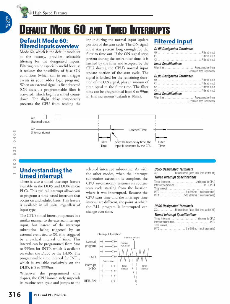
High Speed Features1
-8
00
-6
33
-0
40
5
316 PLC and PC Products
PPLLCC
CCPPUU
SS&&
II//OO
Default Mode 60:filtered inputs overviewMode 60, which is the default mode setat the factory, provides selectablefiltering for the designated inputs.Filtering can be especially useful becauseit reduces the possibility of false ONconditions (which can in turn triggerevents in your ladder logic program).When an external signal is first detected(ON state), a programmable filter isactivated, which begins a timed count-down. The slight delay temporarilyprevents the CPU from reading the
Understanding thetimed interruptThere is also a timed interrupt featureavailable in the DL05 and DL06 microPLCs. This cyclical interrupt allows youto program a time-based interrupt thatoccurs on a scheduled basis. This featureis available in all units, regardless ofinput type.
The CPU’s timed interrupt operates in asimilar manner to the external interruptinput, but instead of the interruptsubroutine being triggered by anexternal event tied to X0, it is triggeredby a cyclical interval of time. Thisinterval can be programmed from 5msto 999ms for INT0, which is availableon either the DL05 or the DL06. Theprogrammable time interval for INT1,which is available exclusively on theDL05, is 5 to 9999ms .
Whenever the programmed timeelapses, the CPU immediately suspendsits routine scan cycle and jumps to the
input during the normal input updateportion of the scan cycle. The ON signalmust stay present long enough for thefilter to time out. If the ON signal stayspresent during the entire filter time, it islatched by the filter and accepted by theCPU during the CPU’s normal inputupdate portion of the scan cycle. Thesignal is latched for the remaining dura-tion of the ON signal, plus an amount oftime equal to the filter time. The filtertime can be programmed from 0 to 99msin 1ms increments (default is 10ms).
selected interrupt subroutine. As withthe other modes, when the interruptsubroutine execution is complete, theCPU automatically resumes its routinescan cycle starting from the locationwhere it was interrupted. Because theCPU scan time and the interrupt timeinterval are different, the point at whichthe RLL program is interrupted canchange over time.
Filtered inputDL05 Designated TerminalsX0. . . . . . . . . . . . . . . . . . . . . . . . . . . . . . . . . . . Filtered inputX1. . . . . . . . . . . . . . . . . . . . . . . . . . . . . . . . . . . Filtered inputX2. . . . . . . . . . . . . . . . . . . . . . . . . . . . . . . . . . . Filtered inputInput SpecificationsFilter time: . . . . . . . . . . . . . . . . . . . . . . . Programmable from
. . . . . . . . . . . . . . . . . . . . . . . . 0-99ms in 1ms increments
DL06 Designated TerminalsX0. . . . . . . . . . . . . . . . . . . . . . . . . . . . . . . . . . . Filtered inputX1. . . . . . . . . . . . . . . . . . . . . . . . . . . . . . . . . . . Filtered inputX2. . . . . . . . . . . . . . . . . . . . . . . . . . . . . . . . . . . Filtered inputX3. . . . . . . . . . . . . . . . . . . . . . . . . . . . . . . . . . . Filtered inputInput SpecificationsFilter time: . . . . . . . . . . . . . . . . . . . . . . . Programmable from
. . . . . . . . . . . . . . . . . . . . . . . . 0-99ms in 1ms increments
DEFAULT MODE 60 AND TIMED INTERRUPTS
DL05 Designated TerminalsX0: . . . . . . . . . . . . . Filtered input (uses filter time set for X1)Timed Interrupt SpecificationsTimed interrupts. . . . . . . . . . . . . . . . . . . . 2 (internal to CPU)Interrupt Subroutine . . . . . . . . . . . . . . . . . . . . . . . INT0, INT1Time interval . . . . . . . . . . . . . . . . . . . . . . . . . . . . . . . . . . . . . INT0 . . . . . . . . . . . . . . . . . . . . 5 to 999ms (1ms increments)INT1 . . . . . . . . . . . . . . . . . . . 5 to 9999ms (1ms increments)
DL06 Designated TerminalsX0: . . . . . . . . . . . . . Filtered input (uses filter time set for X1)
Timed Interrupt SpecificationsTimed interrupts. . . . . . . . . . . . . . . . . . . . 1 (internal to CPU)Interrupt subroutine . . . . . . . . . . . . . . . . . . . . . . . . . . . . INT0Time interval . . . . . . . . . . . . . . . . . . . . . . . . . . . . . . . . . . . . . INT0 . . . . . . . . . . . . . . . . . . . . 5 to 999ms (1ms increments)

317PLC and PC Products
DL05/06 Instruction Set PPLLCC CC
PPUUSS
&&II//OO
317
Timer, Counter, and Shift RegisterInstructions Accumulator/Stack Load and Output Data Differential Instructions
Timer (TMR) Single input incrementing timer with 0.1 second resolution(0-999.9 seconds)
Load (LD) Loads a 16-bit word into the lower 16 bits of theaccumulator/stack.
Positive differential (PD) One-shot output coil. When the input logic produces anoff to on transition, the output will energize for one CPU scan.
Fast Timer (TMRF) Single input incrementing timer with 0.01 second resolution (0-99.99 seconds)
Load Double (LDD) Loads a 32-bit word into the accumulator/stack. Store Positive Differential (STRD) Leading edge triggered one-shot contact. Whenthe corresponding memory location transitions from low to high,the contact comes on for one CPU scan.
Accumulating Timer (TMRA) Two input incrementing timer with 0.1 second resolution (0-9,999,999.9 sec.). Time and enable/reset inputs control the timer.
Load Formatted (LDF) Loads the accumulator with a specified number of con-secutive discrete memory bits.
Store Negative Differential (STRND) Trailing edge triggered one-shot contact.When the corresponding memory location transitions from high to low,the contact comes on for one CPU scan.
Accumulating Fast Timer (TMRAF) Two input incrementing timer with0.1 second resolution (0-99,999.9 sec.). Time and enable/reset inputscontrol the timer.
Load Address (LDA) Loads the accumulator with the HEX value for an octalconstant (address).
Or Positive Differential (ORD) Logically ors a leading edge triggered one-shotcontact in parallel with another contact in a rung.
Counter (CNT) Two input incrementing counter (0-9999). Count and reset inputs control the counter.
Out (OUT) Copies the value in the lower 16 bits of the accumulator to aspecified V memory location.
Out Immediate (OUTI) DL06 Only. Outputs the contents of the accumulator to aspecified V-memory location. The status for each bit of the specified V-memorylocation will reflect the status of the lower 16-bits of the accumulator. Typicallyused for output module V-memory addresses. Allows you to specify the V-locationinstead of the Y location and the number of points as with the OUTIF.Stage Counter (SGCNT) Single input incrementing counter (0-9999)
RST instruction must be used to reset count.Out Double (OUTD) Copies the value in the accumulator to two consecutive V memory locations.
Up Down Counter (UDC) Three input counter (0-99,999,999). Up, down and reset inputs control the counter.
Out Formatted (OUTF) Outputs a specified number of bits (1-32) from theaccumulator to the specified discrete memory locations.
Or Negative Differential (ORND) Logically ors a trailing edge triggered one-shotcontact in parallel with another contact in a rung.
Out Most (OUTM) DL06 Only. Copies the value in the upper 8-bits of thelower accumulator word (1st 16 bits) to the upper 8 bits of a specified V-memory location
Boolean Instructions Comparative Boolean Instructions Immediate InstructionsStore (STR) Begins a new rung or an additional branch in a rung with anormally open contact.
Store if Equal (STRE) Begins a new rung or additional branch in a rung with anormally open comparative contact. The contact will be on when A = B.
Store Immediate (STRI) Begins a rung/branch of logic with a normally open con-tact. The contact will be updated with the current input field status whenprocessed in the program scan.
Store Not (STRN) Begins a new rung or an additional branch in a rungwith a normally closed contact.
Store if Not Equal (STRNE) Begins a new rung or additional branch in a rungwith a normally closed comparative contact. The contact will be on when A =/B.
Store Not Immediate (STRNI) Begins a rung/branch of logic with a normallyclosed contact. The contact will be updated with the current input field statuswhen processed in the program scan.
Or (OR) Logically ors a normally open contact in parallel with anothercontact in a rung.
Or if Equal (ORE) Connects a normally open comparative contact in parallel with another contact. The contact will be on when A = B.
Or Immediate (ORI) Connects a normally open contact in parallel with another contact. The contact will be updated with the current input field status when processed in the program scan.
Or Not (ORN) Logically ors a normally closed contact in parallel withanother contact in a rung.
Or if Not Equal (ORNE) Connects a normally closed comparative contact inparallel with another contact. The contact will be on when A =/ B.
Or Not Immediate (ORNI) Connects a normally closed contact in parallel withanother contact. The contact will be updated with the current input field status when processed in the program scan.
And (AND) Logically ands a normally open contact in series with anoth-er contact in a rung.
And if Equal (ANDE) Connects a normally open comparative contact in serieswith another contact. The contact will be on when A = B.
And Immediate (ANDI) Connects a normally open contact in series with anothercontact. The contact will be updated with the current input field status when processed in the program scan.
And Not (ANDN) Logically ands a normally closed contact in series withanother contact in a rung.
And if Not Equal (ANDNE) Connects a normally closed comparative contact in series with another contact. The contact will be on when A =/ B.
And Not Immediate (ANDNI) Connects a normally closed contact in series withanother contact. The contact will be updated with the current input field statuswhen processed in the program scan.
And Store (ANDSTR) Logically ands two branches of a rung in series. Store (STR) Begins a new rung or additional branch in a rung with a normally open comparative contact. The will be on when A >_ B.
Out Immediate (OUTI) Reflects the status of the rung. The output field devicestatus is updated when the instruction is processed in the program scan.
Or Store (ORSTR) Logically ors two branches of a rung in parallel. Store Not (STRN) Begins a new rung or additional branch in a rung with anormally closed comparative contact. The contact will be on when A >_ B.
Or Out Immediate (OROUTI) Reflects the status of the rung and outputs the dis-crete (ON/OFF) state to the image register. Multiple OR OUT instructions refer-encing the same discrete point can be used in the program. The output fielddevice status is updated when the instruction is processed in the program scan.
Out (OUT) Reflects the status of the rung (on/off) and outputs thediscrete (on/off) state to the specified image register point or memorylocation.
Or (OR) connects a normally open comparative contact in parallel withanother contact. The contact will be on when A >_ B.
Set Immediate (SETI) An output that turns on a point or a range of points. Thereset instruction is used to turn the point(s) off that were set. The output fielddevice status is updated when the instruction is processed in the program scan.
Or Out(OROUT) Reflects the status of the rung and outputs the dis-crete (ON/OFF) state to the image register. Multiple OR OUT instruc-tions referencing the same discrete point can be used in the program.
Or Not (ORN) connects a normally open comparative contact in parallel withanother contact. The contact will be on when A < B.
Reset Immediate (RSTI) an output that resets a point or a range of points. Theoutput field device status is updated when the instruction is processed in theprogram scan.
Not (NOT) Inverts the status of the rung at the point of the instruc-tion.
And (AND) Connects a normally open comparative contact in series withanother contact. The contact will be on when A >_ B.
Set (SET) An output that turns on a point or a range of points. Thereset instruction is used to turn the point(s) OFF that were set ON withthe set instruction.
And Not < (ANDN) Connects a normally closed comparative contact in parallel with another contact. The contact will be on when A < B.
Reset (RST) An output that resets a point or a range of points.Pause outputs (PAUSE) Disables the update for a range of specifiedoutput points.
Logical Instructions (Accumulator)And (AND) Logically ands the lower 16 bits in the accumulator with a V mem-ory location.
Exclusive Or (XOR) Performs an Exclusive Or of the value in the lower 16 bits ofthe accumulator and a V-memory location.
And Double (ANDD) Logically ands the value in the accumulator with an 8-digit constant or a value in two consecutive V-memory locations.
Exclusive Or Double (XORD) Performs an Exclusive Or of the value in the accumu-lator and an 8-digit constant or a value in two consecutive V-memory locations.
And Formatted (ANDF) DL06 Only. Logically ands the value in the accumulatorand a specified range of discrete memory bits (1-32)
Exclusive Or Formatted (XORF) DL06 Only. Performs an exclusive or of the valuein the accumulator and a range of discrete bits (1-32)
And with stack (ANDS) DL06 Only. logically ands the value in the accumulatorwith the first value in the accumulator stack
Exclusive Or with Stack (XORS) DL06 Only. Performs an exclusive or of the valuein the accumulator and the first accumulator stack location
Or (OR) Logically ors the lower 16 bits in the accumulator with a V memory location.
Compare (CMP) Compares the value in the lower 16 bits of the accumulator with a V memory location.
Or Double (ORD) Logically ors the value in the accumulator with an 8-digitconstant or a value in two consecutive V-memory locations.
Compare Double (CMPD) Compares the value in the accumulator with two con-secutive V memory locations or an 8-digit constant.
Or Formatted (ORF) DL06 Only. Logically ors the value in the accumulatorwith a range of discrete bits (1-32)
Compare with Stack (CMPS) DL06 Only. Compares the value in the accumulatorwith the first accumulator stack location
Or with Stack (ORS) DL06 Only. Logically ors the value in the accumulatorwith the first value in the accumulator stack
INSTRUCTION SET
Output indexed (OUTX) DL06 Only. Copies a 16-bit value from the first levelof the accumulator stack to a source address offset by the value in the accu-mulator
Load Immediate (LDI) DL06 Only. Loads the accumulator with the contents of aspecified 16-bit V-memory location. The status for each bit of the specified V-memory location is loaded into the accumulator. Typically used for input moduleV-memory addresses. Allows you to specify the V-location instead of the X loca-tion and the number of points as with the LDIF.
Differential Instructions (cont’d)
Out Immediate Formatted (OUTIF) DL06 Only. Outputs the contents ofthe accumulator to a specified number of consecutive outputs The out-put field devices are updated when the instruction is processed by theprogram scan.
Load Immediate Formatted (LDIF) DL06 Only. Loads the accumulatorwith a specified number of consecutive inputs. The field device status forthe specified inputs points is loaded into the accumulator when theinstruction is executed
Shift Register (SR) Shifts data through a range of control relays witheach clock pulse.The data clock and reset inputs control the shift regis-ter.
Pop (POP) Moves the value from the first level of the accumulator stack to theaccumulator and shifts each value in the stack up one level.
Out Least (OUTL) DL06 Only. Copies the value in the lower 8-bits of theaccumulator to the lower 8-bits of a specified V-memory location
And Positive Differential (ANDD) Logically ands a leading edge triggered one-shotcontact in series with another contact in a rung.
And Negative Differential (ANDND) Logically ands a trailing edge triggered one-shot contact in series with another contact in a rung.

DL05/06 Instruction Set1
-8
00
-6
33
-0
40
5
318 PLC and PC Products
PPLLCC
CCPPUU
SS&&
II//OO
Message InstructionsFault/Data Label (FAULT/DLBL) Displays a V memory value or a data labelconstant to the hand-held programmer or personal computer usingDirectSOFT.
Numerical Constant/ASCII constant (NCON/ACON) Stores constants innumerical or ASCII form for use with other instructions.
Print Message (PRINT) Prints the embedded text or text/data variable mes-sage to the specified communications port. Maximum message length is 255words.
Table Instructions CPU Control Instructions Network InstructionsMove (MOV) Moves the values from one V memory table to another V memo-ry table.
No Operation (NOP) Inserts a no operation coil at specified program address. Read from network (RX) Reads a block of data from another CPU on the network.
End (END) Marks the termination point for the normal program scan. An Endinstruction is required at the end of the main program body.
Write to network (WX) Writes a block of data from the master device to aslave device on the network.
Move Memory Cartridge/Load Label (MOVMC/LDLBL) DL05 Only. Copiesdata between V memory and program ladder memory.
Stop (STOP) Changes the operational mode of the CPU from Run to Program(Stop)
Reset Watchdog Timer (RSTWT) Resets the CPU watchdog timer.
Number Conversion Instructions(Accumulator) Bit Instructions (Accumulator) Interrupt Instructions
Binary (BIN) Converts the BCD value in the accumulator to the equivalentbinary value. The result resides in the accumulator.
Binary Coded Decimal (BCD) Converts the binary value in theaccumulator to the equivalent BCD value. The result resides in the
accumulator.
Sum (SUM) Counts the number of bits set to "1" in the accumulator. TheHEX result resides in the accumulator..
Shift Left (SHFL) Shifts the bits in the accumulator a specified number ofplaces to the left.
Interrupt Routine/Interrupt Return/Interrupt Return Conditional(INT/IRT/IRTC) When a hardware or software interrupt occurs, the interruptroutine will be executed. The INT instruction is the beginning of the interruptroutine. The interrupt routine is terminated with an IRT of the interrupt rou-tine. The ininterrupt routine is terminated with an IRT instruction (unconditional inter-rupt return). When a interrupt return is reached the execution of the pro-gram continues from the instruction where the program execution was prior to theinterrupt.
Invert (INV) Takes the one's complement of the 32-bit value in theaccumulator. The result resides in the accumulator.
ASCII to HEX (ATH) Converts a table of ASCII values to a table ofhexadecimal values.
Shift Right (SHFR) Shifts the bits in the accumulator a specified number ofplaces to the right.
Enable Interrupt (ENI) Enables hardware and software interrupts to beacknowledged.
Disable Interrupt (DISI) Disables hardware and software interrupts from beingacknowledged.HEX to ASCII (HTA) Converts a table of hexadecimal values to a table of
ASCII values.
Gray Code to BCD (GRAY) Converts a 16-bit GRAY code value in the accu-mulator to a corresponding BCD value. The result resides in the accumulator.
Encode (ENCO) Encodes the bit position set to 1 in the accumulator, andreturns the appropriate binary representation in the accumulator.
Decodes (DECO) Decodes a 5 bit binary value (0-31) in the accumulator bysetting the appropriate bit position to 1 in the accumulator. Shuffle Digits (SFLDGT) Shuffles a maximum of 8 digits, rearranging them in
a specified order. The result resides in the accumulator."
Radian Real Conversion (RADR) DL06 Only. Converts the real degree value inthe accumulator to the equivalent real number in radians. The result residesin the accumulator
Set Bit (SETBIT) DL06 Only. Sets a single bit (to a 0) in a V-memory location
INSTRUCTION SET
Degree Real Conversion (DEGR) DL06 Only. Converts the real radian value inthe accumulator to the equivalent real member of degrees. The result residesin the accumulator
Reset Bit (RSTBIT) DL06 Only.. Resets a single bit (to a 0) in a V-memorylocation
Math Instructions (Accumulator)Add (ADD) Adds a BCD value in the lower 16 bits in the accumulator with a Vmemory location. The result resides in the accumulator.
Divide Binary (DIVB) Divides the binary value in the lower 16 bits in the accu-mulator by a value which is either a V memory location or a 16-bit constant. The result resides in the accumulator.
Add Double (ADDD) Adds a BCD value in the accumulator with two consecutive V memory locations or an 8-digit constant. The result resides inthe accumulator.
Add Formatted (ADDF) DL06 Only. Adds the BCD value in the accumulatorto a value which is a range of discrete bits (1-32). The result resides in theaccumulator
Subtract (SUB) Subtract a BCD value, which is either a V memory location or a 4-digit constant from the lower 16 bits in the accumulator. Theresult resides in the accumulator.
Subtract Formatted (SUBF) DL06 Only. Subtracts a BCD value which is arange of discrete bits (1-32) from the BCD value in the accumulator. Theresult resides in the accumulator
Subtract Double (SUBD) Subtracts a BCD value, which is either two consecutive V memory locations or an 8-bit constant, from a value in theaccumulator. The result resides in the accumulator.
Multiply Formatted (MULF) DL06 Only. Multiplies a BCD value in the lower16-bits in the accumulator by a BCD value which is a range of discrete bits(1-16). The result resides in the accumulator
Multiply (MUL) Multiplies a BCD value, which is either a V memory location or a 4-digit constant, by the value in the lower 16 bits in the accumulator. The result resides in the accumulator.
Divide Formatted (DIVF) DL06 Only. Divides the BCD value in the lower 16-bits in the accumulator by the BCD value which is a range of discrete bits (1-16). The result resides in the accumulator
Multiply Double (MULD) Multiplies a BCD value contained in two consecutive V memory locations by the value in the accumulator. The resultresides in the accumulator.
Add Top of Stack (ADDS) DL06 Only. Adds the BCD value in the accumulatorwith the BCD value in the first level of the accumulator stack. The resultresides in the accumulator
Divide (DIV) Divides a BCD value in the accumulator by a BCD value which iseither a V memory location or a 4-digitconstant. The result resides in the accumulator.
Subtract Top of Stack (SUBS) DL06 Only. Subtracts the BCD value in thefirst level of the accumulator stack from the BCD value in the accumulator.The result resides in the accumulator
Divide Double (DIVD) Divides a BCD value in the accumulator by a BCDvalue which is either two consecutive V memory locations or a 8-digit con-stant. The result resides in the accumulator.
Multiply Top of Stack (MULS) DL06 Only. Multiplies a 4-digit BCD value inthe first level of the accumulator stack by a 4-digit BCD value in the accumu-lator. The result resides in the accumulator
Add Binary (ADDB) Adds the binary value in the lower 16 bits of the accumulator to a value which is either a V memory location or a 16-bit constant. The result resides in the accumulator.
Subtract Binary (SUBB) Subtract a 16-bit binary value, which is either a Vmemory location or a 16-bit constant, from the lower 16 bits in the accumulator. The result resides in the accumulator.
Add Binary Double (ADDBD) DL06 Only. Adds the binary value in the accu-mulator to a value which is either two consecutive V-memory locations or a32-bit constant. The result resides in the accumulator
Subtract Binary Double (SUBBD) DL06 Only. subtracts a 32-bit binary value,which is either two consecutive V-memory locations or a 32-bit constant,from the value in the accumulator. The result resides in the accumulator
Multiply Binary (MULB) Multiples a 16-bit binary value, which is either a Vmemory location or a 16-bit constant, by the lower 16 bits in the accumulator. The result resides in the accumulator.
Divide by Top of Stack (DIVS) DL06 Only. Divides the 8-digit BCD value inthe accumulator by the 4-digit BCD value in the first level of the accumulatorby the 4-digit BCD value in the first level of the accumulator stack. The resultresides in the accumulatorAdd Binary Top of Stack (ADDBS) DL06 Only. Adds the binary value in theaccumulator with the binary value in the first accumulator stack location. Theresult resides in the accumulator
Subtract Binary Top of Stack (SUBBS) DL06 Only. Subtracts the binary valuein the first level of the accumulator stack from the binary value in the accu-mulator. The result resides in the accumulator
Multiply Binary Top of Stack (MULBS) DL06 Only. Multiplies the 16-bit bina-ry value in the first level of the accumulator stack by the 16-bit binary valuein the accumulator. The result resides in the accumulator
Divide Binary Top of Stack (DIVBS) DL06 Only. Divides a value in the accu-mulator by the binary value in the top location of the stack. The accumulatorcontains the result
Increment (INC) Increments a BCD value in a specified V memory location by1 each time the instruction is executed.
Decrement (DEC) Decrements a BCD value in a specified V memory locationby 1 each time the instruction is executed.
Increment Binary (INCB) Increments a binary value in a specified V memorylocation by 1 each time the instruction is executed.
Decrement Binary (DECB) Decrements a binary value in a specified V memory location by 1 each time the instruction is executed.

319PLC and PC Products
DL05/06 Instruction Set PPLLCC CC
PPUUSS
&&II//OO
INSTRUCTION SETProgram Control Instructions RLLPLUS Programming Instructions Drum Instructions
For/Next (FOR/NEXT) Executes the logic between the FOR and NEXT instructions a specified number of times.
Initial stage (ISG) The initial stage instruction is used for a starting point foruser application program. The ISG instruction will be active on power up andPROGRAM to RUN transitions.
Tuned Drum with Discrete Outputs (DRUM) Time driven drum with up to 16steps and 16 discrete output points. Output status is written to the appropri-ate output during each step. Specify a time base per count (in milliseconds).Each step can have a different number of counts to trigger the transition tothe next step. Also define preset step as destination when reset occurs.
Go to Subroutine/Subroutine Return Conditional/Subroutine Return(GTS/SBR w/RT) When a GTS instruction is executed the program jumps tothe SBR (Subroutine). The subroutine is terminated with a RT instruction(unconditional return). When a return is executed, the program continuesfrom the instruction after the calling GTS instruction.
Stage (SG) Stage instructions are used to create structured programs. Theyare program segments which can be activated or deactivated with controllogic.
Jump (JMP) Normally open coil that deactivates the active stage and activates a specified stage when there is power flow to the coil.
Time & Event Drum with Discrete Outputs (EDRUM) Time and/or eventdriven drum with up to 16 steps and 16 discrete output points. Output statusis written to the appropriate output during each step. Specify a time base percount (in milliseconds). Each step can have a different number of counts andan event to trigger the counting. Once the time has expired, a transition tothe next step occurs. Also define preset step as destination when resetoccurs.
Master Line Set/Master Line Reset (MLS/MLR) Allows the program to control sections of ladder logic by forming a new power rail. The MLS marksthe beginning of a power rail and the MLR marks the end of the power railcontrol.
Not Jump (NJMP) Normally closed coil that deactivates the active stage andactivates a specified stage when there is power flow to the coil.
Converge Stages (CV) Converge stages are a group of stages that when allstages are active the associated converge jump(s). (CVJMP)will activateanother stage(s). One scan after the CVJMP is executed, the converge stageswill be deactivated.
Converge Jump (CVJMP) Normally open coil that deactivates the active CVstages and activates a specified stage when there is power flow to the coil.
Time and Event Drum with Discrete Outputs and Output Mask (MDRMD)DL06 Only. Time and/or event driven drum with up to 16 steps and 16 dis-crete output points. Actual output status is the result of a bit-by-bit ANDbetween the output mask and bit mask in the step. Specify a time base percount (in milliseconds). Each step can have a different number of counts andan event to trigger the counting. Once the time has expired, a transition tothe next step occurs. Also define present step as destination when resetoccurs.
Time and Event Drum with Word Output and Output Mask (MDRMW) DL06Only. Time and/or event driven drum with up to 16 steps and a single V-memory output location. Actual output word is the result of a bit-by-bit ANDbetween the word mask and the bit mask in the step. Specify a time base percount (in milliseconds). Each step can have a different number of counts andan event to trigger the counting. Once the time has expired, a transition tothe next step occurs. Also define preset step as destination when resetoccurs.
ASCII Instructions (DL06 only) LCD Display Instructions (DL06 only)ASCII IN (AIN) Configures port 2 to read raw ASCII input strings.
ASCII Find (AFIND) Searches ASCII strings in V-memory to find a specificportion of the string.
ASCII IN (AEX) Extracts a specific portion from an ASCII string.
Compare V-memory (CMPV) Compares two blocks of V-memory.
Swap Bytes (SWAPB) Swaps V-memory bytes.
Print to V-memory (VPRINT) Used to send pre-coded ASCII strings to a pre-defined V-memory address when enabled.
Print from V-memory (PRINTV) Used to write raw ASCII string out of port 2when enabled.
Fill (FILL) Fills a table of specified V-memory locations with a value which iseither a V-memory location or a 4-digit constant.
Find (FIND) Finds a value in a V-memory table and returns the table positioncontaining the value to the accumulator.
Find Greater Than (FDGT) Finds a value in a V-memory table which is greaterthan the specified search value. The table position containing the value isreturned to the accumulator.
Find Block (FINDB) Finds a block of data values in a V-memory table andreturns the starting address of the table containing the values to the accu-mulator.
Table to Destination (TTD) Moves the value form the top of a V-memorytable to a specified V-memory location. The table pointer increments eachscan.
Remove from Bottom (RFB) Moves the value from the bottom of a v-memorytable to a specified V-memory location. The table pointer increments eachscan.
Source To Table (STT) Moves a value from a specified V-memory location toa V-memory table. The table pointer increments each scan.
Remove from Top (RFT) Pops a value from the top of a V-memory table andstores it in a specified V-memory location. All other values in the V-memorytable are shifted up each time a value is popped from the table.
Add To Top of Table (ATT) Pushes a value from a specified V-memory loca-tion onto the top of a V-memory table. All other values in the V-memorytable are shifted down each time a value is pushed onto the table.
Table Shift Left (TSHFL) Shifts s specified number of bits to the left in a V-memory table.
Table Shift Right (TSHFR) Shifts a specified number of bits to the right in aV-memory table.
Move Block (MOVBLK) Copies a specified number of words from a DataLabel area of program memory (ACON, NCON) to a V-memory area.
And Move (ANDMOV) Copies data from a table to the specified location,ANDing each word with the accumulator data as it is written.
Or Move (ORMOV) Copies data from a table to the specified memory loca-tion, ORing each word with the accumulator data as it is written.
Exclusive Or Move (XORMOV) Copies data from a table to the specifiedmemory location, XORing each word with the accumulator data as it is writ-ten.
MODBUS Read (MRX) Used CPU port 2 to read a block of data from MOD-BUS RTU devices on the network.
MODBUS Write (MWX) Writes a block of data from CPU port 2 to MODBUSRTU devices on the network.
MODBUS Instructions (DL06 only)
Trigonometric Instructions (DL06 only)Square Root Real (SQRTR) Takes the square root of the real number storedin the accumulator. The result resides in the accumulator.
Sine Real (SINR) Takes the sine of the real number stored in the accumulator.The result resides in the accumulator.
Cosine Real (COSR) Takes the cosine of the real number stored in the accu-mulator. The result resides in the accumulator.
Tangent Real (TANR) Takes the tangent of the real number stored in theaccumulator. The result resides in the accumulator.
ARC Sine Real (ASINR) Takes the inverse sine of the real number stored inthe accumulator. The result resides in the accumulator.
ARC Cosine Real (ACOSR) Takes the inverse cosine of the real numberstored in the accumulator. The result resides in the accumulator.
ARC Tangent Real (ATANR) Takes the inverse tangent of the real numberstored in the accumulator. The result resides in the accumulator.
Extended Table Instructions (DL06 only)
LCD Configures LCD display.
Block Call/Block/Block End (BCALL w/BLK and BEND) DL06 Only BCALL is anormally open coil that activates a block of stages when there is power flowto the coil. BLK is the label which marks the beginning of a block of stages.Bend is a label used to mark the end of a block of stages
SOLITON CONTROLES INDUSTRIAIS LTDARua Alfredo Pujol, 1010 - Santana - São Paulo - SP. Tel: 11 - 6950-1834 / Fax: 11 - 6979-8980 - e-mail: [email protected]
www.soliton.com.br - e-mail: [email protected]ções sobre programação do PLC KOYO

![SINC Barking and Dagenham · Gascoigne Road Pumping Station Rough : B&DL04 : St Chad’s Park : B&DL05 : Valence House Gardens [B&DL0 6 . Morrison Road Rough . now upgraded to B&DBII10]](https://static.fdocuments.us/doc/165x107/5f81dd37f1155e387a6de3dd/sinc-barking-and-dagenham-gascoigne-road-pumping-station-rough-bdl04-st.jpg)