Division 1 4-H Electric
17
4-H 421 4-H Electric Division 1
Transcript of Division 1 4-H Electric

4-H 421
4-H Electric
Division 1

1
Welcome to the 4-H Electric Project! The first division ofthe Electricity project is intended for youth in grades 3 or4 or those who are just beginning to explore electricity.
In this project, you will be making and exhibiting acircuit board. This board will help you understand howsimple electrical circuits work. You will also learn aboutelectrical safety.
Before you begin this project you will need to gather thesupplies you’ll be using to complete the circuit board.
GETTING ON TRACK WITH ELECTRICITY
• Battery clip withsolder terminals
• Two single strandinsulated bell wires(one black and onewhite)
• Two 11/2 voltflashlight bulbs
• Two miniaturesockets with solderterminals
• A single pole,single throwknife bladeswitch
Written by: Karen Tormoehlen
Reviewed by:Tom Taylor, Boone County REMCWayne Newhart, retired, Tipmont REMCBetty Baute, Jackson County REMCFred Bauman, Fulton County REMCGalen Eberhart, Southeastern Indiana REMCRobert Meyer, Rush-Shelby EnergyEd Gilbert, Cinergy/PSIBrandon Stevens, 4-H volunteerRobert Wilson, Wabash Valley PowerRoger Tormoehlen, Purdue University
Sponsors of the Indiana 4-H Electric Program:Indiana Statewide Association ofRural Electric Cooperatives, Inc.Indiana Electric Association
• Board approximately 51/2" x 51/2" x 3/4"• Ruler• Pencil• Hammer• Soldering iron or gun• Electrical solder (rosin core)• Pocket knife• Screwdriver• Wire cutters/strippers• Two "C" flashlight batteries• 8 small screws (1/2 inch long or shorter)
A circuit board kit is available from your county extension office. It will include:
You will need to gather a few tools/supplies to complete the circuit board:

2
Things that use electricity Electrical Outlet (AC) Battery(DC)
1.
2.
3.
4.
5.
6.
7.
8.
9.
10.
BATTERY VS. WALL-BASED ELECTRICITY
ACTIVITY
Did the number of things in your house that use electricity surprise you? Do you think you
listed all of them?
If the electricity was off at your house for a few days, would there be many things you
couldn’t use? Which of these items would you miss using the most? What would you use
instead of them?
Let’s get started!Electricity makes our life easier. It helps play our music, cool our house and cook our food.
Think of everything you do. How does electricity help you?
Do you have an alarm clock wake you in the morning? Do
you have toast for breakfast? Do you have a favorite TV
show you like to watch?
Take a few minutes to list the things in your house that use
electricity. List things that use AC (Alternating Current)
electricity (i.e., things that plug into the electrical outlet in
the wall) and those that use DC (Direct Current) electricity
(i.e., things that use batteries).

3
When you plug the television into an electrical wall circuit, why does it work?
When you put batteries in your portable CD player, why does it play music?
To find the answer to these questions, you need to first learn a little bit about what
electricity is.
Electricity is a form of energy used to produce motion,
light, and heat. Electrical companies make electricity at
generating plants. Batteries, through a chemical reaction,
can also make it.
What makes this energy? The energy is formed by
tiny particles called electrons. These electrons are
so small they cannot even be seen with an ordinary
microscope. These electrons flow much like water
flows out of a faucet. The flow of these electrons
creates energy and the energy made by this
movement is electricity. When these electrons flow
they make electric current.
Have you ever played with a train set? You lay down the tracks so the
engine has a path to follow.
With electricity you will also need a “path” for it to follow. This
path is usually wire (like the black and white wires that came
with your circuit board kit). These wires form the path or
circuit the electrons will travel to deliver the energy.
For this energy (electrons) to flow, it will
need something to push it. Think back to the
train set. When you set the engine on the
track, does it move? Not by itself. It moves if
you turn it on (battery operated) or if you
push it with your hand. In other words, the
train requires a “push.”
The same is true for electricity. The push to move the electrons
needs to come from either a battery or an appliance plugged
into a wall circuit.
With the train, the track provides the “path.” And the
hand provides the “push.”
HOW DOES ELECTRICITY MAKE THINGS WORK
PUSHER
The Electrical Circuit
Electrons
ATOM

4
With the electrical circuit, the wire provides the “path” for
the electrons and the batteries provide the “push.”
Circuits are either “closed” or “open.”
Think again about the train track. When all the track
sections are in place, the train has a clear path to travel.
With electricity, this would be a “closed circuit.” In
other words, there is nothing stopping the electricity
(electrons) from moving along the path (wire).
If you take that same train track and remove a section of the tracks, the train will
have problems moving on its path. The engine will stop or wreck at the gap.
The same is true for electricity. If
there is a break in the path (wire), the
electricity will not be able to continue
along the path [from the positive (+)
end of the battery to the negative (-)
end of the battery]. This is considered
an “open circuit.”
Open
CircuitOpen
Circuit
Current: Movement of the electrons through a path.
Volt: Measure of the tendency of electrons to move when “pushed.”
Voltage: Amount of “push” behind the electrons.
Amperage: The rate of flow of electrical current.
Watts: Measure of electrical power.
Ohm: A unit measuring resistance.
Knowing the Terms
Open vs. Closed Circuits
Pusher
Path

5
Conductor
Insulator
COPPER WIRE
Conductor
Insulator
WOODEN RULER
Conductor
Insulator
PAPER
Conductor
Insulator
BOLT
Conductor
Insulator
PAPER CLIP
Conductor
Insulator
PLASTIC PLUGCOVER
Conductor
Insulator
RUBBER BAND
Conductor
Insulator
ALL METALSCISSORS
Conductor
Insulator
SCREW
Conductor
Insulator
RUBBER TIRE
CONDUCTOR OR INSULATOR
ACTIVITY
What You Will Learn• What items are conductorsand which ones are insulators
Things Needed• Pencil or pen• This manual
What to Do• Identify each of the itemsas either a conductor or aninsulator.
*Ask your parents or anadult friend to check youranswers. Were you suprisedas to which ones wereconductors and insulators?
To have an electrical circuit there needs to be a path. Some materials make better paths
than others. This is because they are conductors. A conductor allows the electricity
(electrons) to move easily along the path. There are several materials that make good
conductors. They include: silver, copper, iron and aluminum.
On the other hand, there are materials electricity (electrons) has trouble moving
through. These are called insulators. They include rubber, most plastics, dry wood
and glass. These materials are used to cover the conductors to help make them safer (so
we don’t get electrocuted while handling).
Take out the black and white wires that came with your circuit board kit. If
you look at the ends you can see the metal on the inside. They are covered
with plastic to make them safer to handle. Depending on the amount of
electricity passing through the wires, there will be either a little or a lot of
insulation to protect us from harm.
Conductors and Insulators

6
LET'S BE FRIENDS WITH ELECTRICITY
Electricity can be our “friend” but it can also be dangerous. Our bodies are good conductors. If you
come in contact with electric current it can pass through your body. When this happens you may get
a shock, burn, or serious injury.
(NOTE: Battery current iscompletely safe. Household currentcan be very dangerous.)
To make electricity safe, all wiring,
fittings, insulation, cords, and plugs
must be in good condition. You can
be a detective and find defects in
the electrical equipment in your
home. If you find frayed or broken
cords, you should tell your parents.
Remember: SAFETY
1. Do not touch broken or frayed wires, insulators, fittings or other wiring
equipment.
2. Do not use an electrical appliance near a sink, bathtub, or other wet place.
3. Do not play with electrical games or use equipment on a wet floor or carpet.
4. Do not play in a flooded basement.
5. Fly kites only in open places not near power lines. Never try to retrieve a kite
in a power line. Always use non-metallic kite string.
6. Always take hold of the plug instead of the cord when removing a cord from
a socket.
frayed
wire
Safety Tips

7
With a parent or adult helper, go on a hazard hunt to see how many electrical hazards you can find. Look
for broken insulation, worn cords, splices that are not properly soldered and taped, loose connections or
defective switches. You may want to report to your club on the results of your hazard hunt.
List the hazards, their locations, and what you did about them. Fill out the following sheet to record
the results of your hazard hunt.
HAZARD OR NOT?
ACTIVITY
HAZARD LOCATION WHAT I DID
Loose prong on cap of lamp cord Living Room Helped Dad replace with new cap
Electrical Hazard Hunt
8
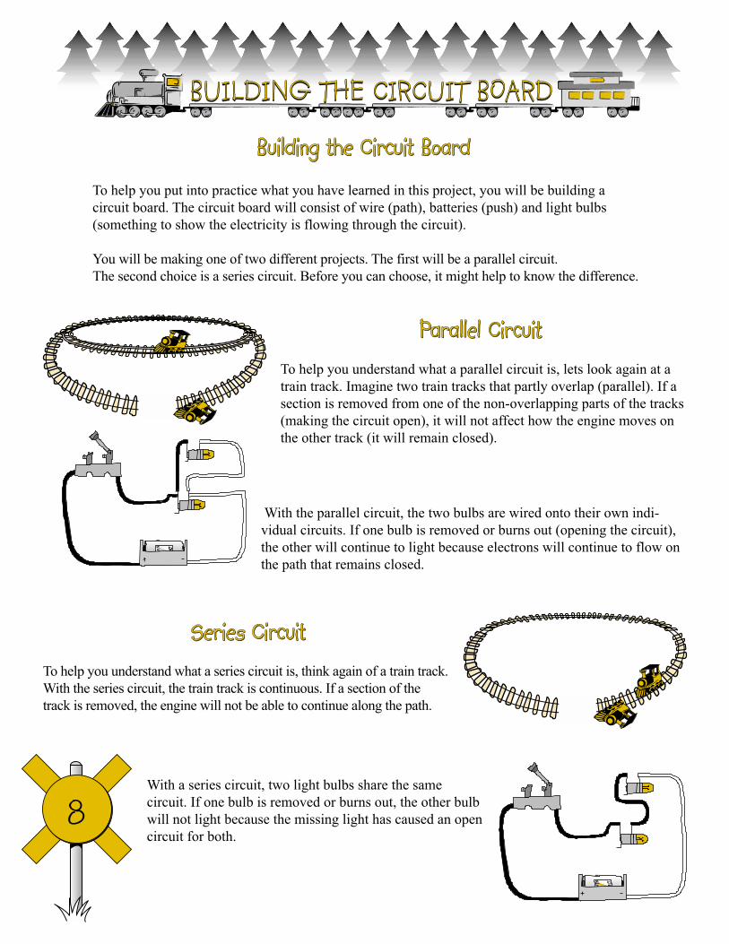
To help you put into practice what you have learned in this project, you will be building a
circuit board. The circuit board will consist of wire (path), batteries (push) and light bulbs
(something to show the electricity is flowing through the circuit).
You will be making one of two different projects. The first will be a parallel circuit.
The second choice is a series circuit. Before you can choose, it might help to know the difference.
To help you understand what a parallel circuit is, lets look again at a
train track. Imagine two train tracks that partly overlap (parallel). If a
section is removed from one of the non-overlapping parts of the tracks
(making the circuit open), it will not affect how the engine moves on
the other track (it will remain closed).
With the parallel circuit, the two bulbs are wired onto their own indi-
vidual circuits. If one bulb is removed or burns out (opening the circuit),
the other will continue to light because electrons will continue to flow on
the path that remains closed.
To help you understand what a series circuit is, think again of a train track.
With the series circuit, the train track is continuous. If a section of the
track is removed, the engine will not be able to continue along the path.
With a series circuit, two light bulbs share the same
circuit. If one bulb is removed or burns out, the other bulb
will not light because the missing light has caused an open
circuit for both.
BUILDING THE CIRCUIT BOARD
Building the Circuit Board
Parallel Circuit
Series Circuit

9
First you must decide if you are going to make a Series or Parallel
Circuit. Once you have decided on the type of circuit you are going to
make you are ready to begin.
The first thing you will do is make the board.
• Find a board about 3/4" thick by 51/2" wide by 51/2" long.HINT: A 1" x 6" piece of lumber cut to 51/2" long will be approximately3/4" thick by 51/2" wide by 51/2".
• Sand and paint, varnish, or stain your board.
LET'S MAKE A CIRCUIT BOARD
Identify where the various components are to be mounted.
• Mark on the board where you want the various components (battery holder, knife bladeswitch, and bulb holders) using a pencil and ruler as indicated in. You may use thetemplate on the web at www.four-h.purdue.edu/electric/
Attach the various components to the board.
• Attach the lamp sockets, battery clip, and the single poleswitch to the board with small screws. (With someswitches, it is easier to attach the black wires to the switchbefore mounting.)

10
Parallel Circuit1. Lay out the circuit path.
2. Use the black wire for the positive side of the circuit
(+ end of the battery). With the pocket knife,
carefully remove about 1/2 inch of insulation from
each of the wires.
3. Attach a black wire to the positive (+) terminal (A) of
the battery clip, and run this under the screw on the
open side (C) of the knife switch. Always wrap wire
clockwise around screws. Tighten the screw.
4. Attach one black wire under the screw on the knife
blade end (D) of the switch, and run to the back
terminals (G and I) of the lamp sockets (E) and (F).
5. Attach a white wire to the front terminal (J) of lamp
socket (F) and run it to the front terminal (H) of lamp
socket (E). Attach a second white wire to front
terminal (H) of lamp socket (E) to the negative (-)
terminal of the battery, clip (B).
6. Close the switch. Both bulbs will light. If they don’t,
check the connections; make sure the contacts and
wires are clean and free from corrosion.
7. After checking to see if both bulbs light up, solder or
firmly attach the wires to the terminals. For tips on
soldering see “How to Solder” on page 11.
Series Circuit1. Lay out the circuit path. Use the black wire for the
positive side of the circuit (+ end of the battery).
With the pocket knife, carefully remove about 1/2
inch of insulation from each of the wires.
2. Attach a black wire to the positive (+) terminal (A) of
the battery clip, and run this under the screw on the
open side (C) of the knife switch. Always wrap wire
clockwise around screws. Tighten the screw.
3. Attach a black wire under the screw on the knife
blade end of the switch (D), and run it to the back
terminal (G) of lamp socket (E).
4. Attach a black wire to the front terminal (H) of lamp
socket (E), and run to the back terminal (I) of lamp
socket (F).
5. Attach a white wire to the front terminal (J) of lamp
socket (F), and run to the negative (-) end of the
battery clip (B).
6. After checking to see if both bulbs light up, solder or
firmly attach the wires to the terminals. For tips on
soldering see “How to Solder” on page 11.
Follow the instructions above for the Series or Parallel
circuit depending on which one you have decided to make.
Wiring the Circuit
You need to label your circuit board either “Series Circuit” or “Parallel Circuit”
Parallel Circuit Series Circuit

11
To make good, lasting connections to the battery clip
and permanent connections in the circuit for your
exhibit, you will need to solder the connections. To
solder the connection follow these three steps:
1. Be sure all metal-to-metal connections are clean
and tight.
2. Heat the connection by touching the hot solder
gun to it.
3. Next touch the solder to the connection. (Be sure
you use rosin core solder only.)
4. Let the connection melt the solder; DO NOT let
the soldering gun do it.
IMPORTANT: Only a small amount of solder is needed.
1. Always wear eye protection (i.e. safety goggles or
glasses).
2. Be careful not to get burned by the iron’s tip. The
tip of the soldering iron can reach 600 degrees F.
3. Do not solder near flammable materials such as
gasoline.
4. Use a scrap piece of wood to solder on when
working on a wooden table. The scrap piece of
lumber will protect the table’s top.
How to Solder
Safety when Soldering
sponge(cleans the
soldering tip)
cord
handle
grip
tipstand
sponge(cleans the
soldering tip)
cord
handle
grip
tipstand
12
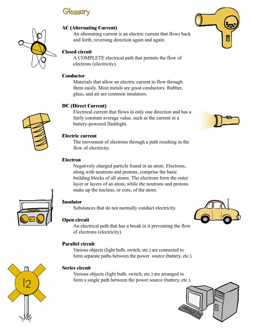
AC (Alternating Current)
An alternating current is an electric current that flows back
and forth, reversing direction again and again.
Closed circuit
A COMPLETE electrical path that permits the flow of
electrons (electricity).
Conductor
Materials that allow an electric current to flow through
them easily. Most metals are good conductors. Rubber,
glass, and air are common insulators.
DC (Direct Current)
Electrical current that flows in only one direction and has a
fairly constant average value, such as the current in a
battery-powered flashlight.
Electric current
The movement of electrons through a path resulting in the
flow of electricity.
Electron
Negatively charged particle found in an atom. Electrons,
along with neutrons and protons, comprise the basic
building blocks of all atoms. The electrons form the outer
layer or layers of an atom, while the neutrons and protons
make up the nucleus, or core, of the atom.
Insulator
Substances that do not normally conduct electricity.
Open circuit
An electrical path that has a break in it preventing the flow
of electrons (electricity)
Parallel circuit
Various objects (light bulb, switch, etc.) are connected to
form separate paths between the power source (battery, etc.).
Series circuit
Various objects (light bulb, switch, etc.) are arranged to
form a single path between the power source (battery, etc.).
Glossary
13
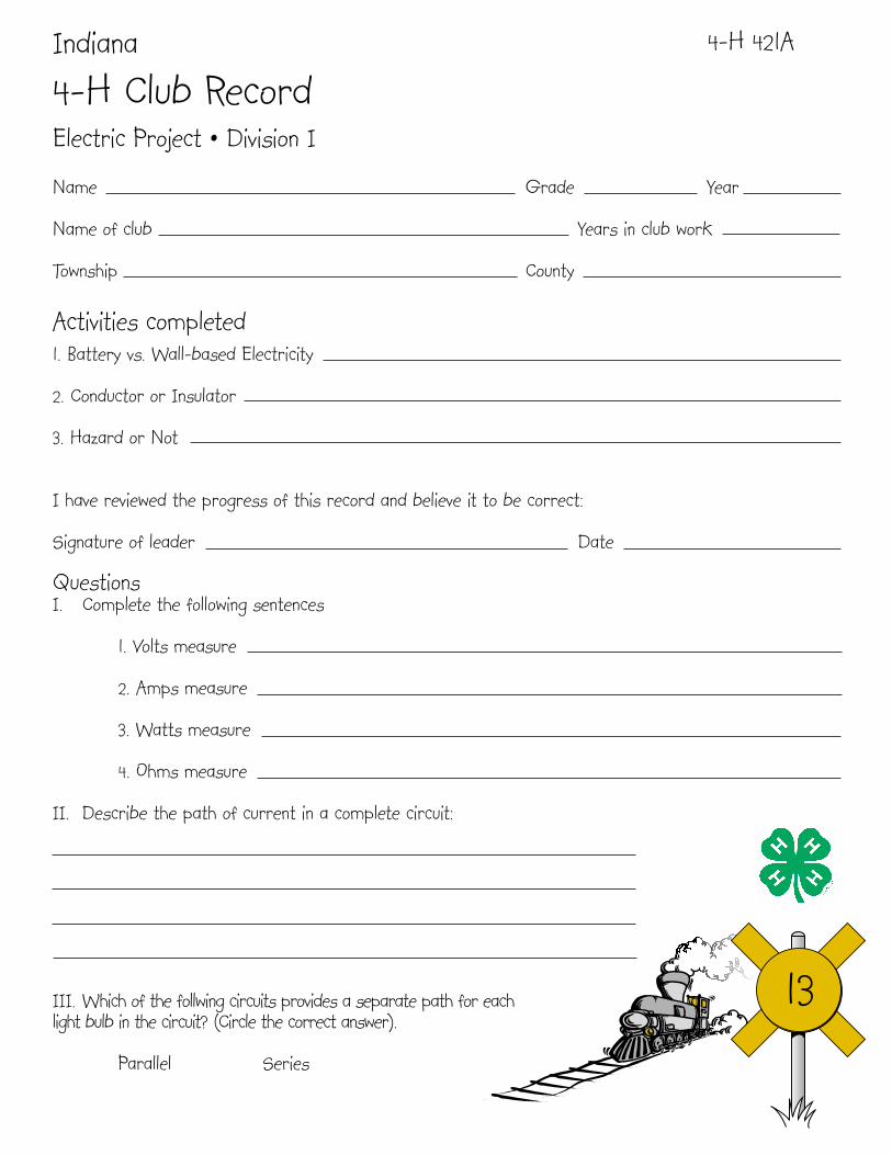
Indiana
4-H Club RecordElectric Project • Division I
Name Grade Year
Name of club Years in club work
Township County
Activities completed1. Battery vs. Wall-based Electricity
2. Conductor or Insulator
3. Hazard or Not
I have reviewed the progress of this record and believe it to be correct:
Signature of leader Date
QuestionsI. Complete the following sentences
1. Volts measure
2. Amps measure
3. Watts measure
4. Ohms measure
II. Describe the path of current in a complete circuit:
III. Which of the follwing circuits provides a separate path for eachlight bulb in the circuit? (Circle the correct answer).
Parallel Series
4-H 421A

14

15
4-H 421BWhat I Have Done
Date Completed(Do at least 2)
1. Make a circuit board and demonstrate parallel and series circuit.
2. Conduct a hazard hunt and make a report by completing the chart in the manual.
3. Give a demonstration on something you learned in this division.
4.
5.
What I Have Learned
1. What materials does electricity pass through easily?
What are these materials called?
2. What types of material does electricity have trouble passing through?
What are these called?
3. True or False: Our bodies are good conductors of electricity.
4. What are some electrical defects you should look for during your hazard hunt?
Leader’s Signature
Date
4-H 421
4-H Electric
Division 1