GENER AL h ELECTRIC - NRC
15
. . GENER AL h ELECTRIC " " ^ " '"""" ENGINEERING GENERAL ELECTRIC COMPANY. P.O. BOX 460, PLEAsAN CN. C."50RNIA 94566 DIVISION September 21, 1979 Mr. Robert W. Reid, Chief Operating Reactors Branch #4 Office of Nuclear Reactor Regulation U.S. Nuclear Regulatory Commission Washington, D.C. 20555 Subject: Response to Recent Request for Additional Information - General Electric Test Reactor - Docket 50-70 Reference: (1) Letter from Robert W. Reid (NRC) to R. W. Darmitzel (GE),datedAugust 16, 1979 Dear Mr. Reid: Attachment 1 provides responses to all eight (8) items contained in Reference 1. If we can be of further assistance in this matter, please let me know. Very truly yours, hv(0vu~& R. W. Dannitzel Manager Irradiation Processing Operation Attach. 7909250690 * 1018 335 -
Transcript of GENER AL h ELECTRIC - NRC
. .
GENER AL h ELECTRIC" " ^ " '""""
ENGINEERING
GENERAL ELECTRIC COMPANY. P.O. BOX 460, PLEAsAN CN. C."50RNIA 94566 DIVISION
September 21, 1979
Mr. Robert W. Reid, ChiefOperating Reactors Branch #4Office of Nuclear Reactor RegulationU.S. Nuclear Regulatory CommissionWashington, D.C. 20555
Subject: Response to Recent Request for Additional Information -General Electric Test Reactor - Docket 50-70
Reference: (1) Letter from Robert W. Reid (NRC) to R. W. Darmitzel(GE),datedAugust 16, 1979
Dear Mr. Reid:
Attachment 1 provides responses to all eight (8) items containedin Reference 1.
If we can be of further assistance in this matter, please let meknow.
Very truly yours,
hv(0vu~&R. W. DannitzelManagerIrradiation Processing Operation
Attach.
7909250690*
1018 335-

.
External DistributionResponse to 8 Structural Modifications Questions
of August 16, 1979
9/21/79
G. L. EdgarDr. Harry Foreman (ASLB)
Mr. Herbert Grossman (ASLB)Mr. Robert KratzkeNRC, Region V
Friends of the EarthCongressman Dellums
E. A. FirestoneNRC Washington (40)
Mr. Gustave A. Linenberger (ASLB)
Advisory Committee on Reactor Safeguards
1018 336
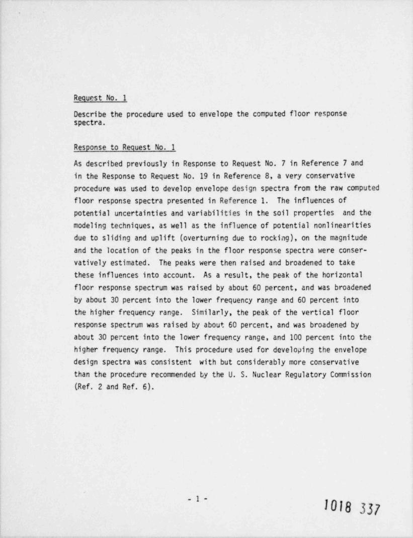
Request No. 1
Describe the procedure used to envelope the computed floor responsespectra.
Response to Request No. 1
As described previously in Response to Request No. 7 in Reference 7 andin the Response to Request No. 19 in Reference 8, a very conservativeprocedure was used to develop envelope design spectra from the raw computed
floor response spectra presented in Reference 1. The influences ofpotential uncertainties and variabilities in the soil properties and themodeling techniques, as well as the influence of potential nonlinearitiesdue to sliding and uplift (overturning due to rocking), on the magnitudeand the location of the peaks in the floor response spectra were conser-vatively estimated. The peaks were then raised and broadened to takethese influences into account. As a result, the peak of the horizontalfloor response spectrum was raised by about 60 percent, and was broadened
by about 30 percent into the lower frequency range and 60 percent intothe higher frequency range. Similarly, the peak of the vertical floor
response spectrum was raised by about 60 percent, and was broadened by
about 30 percent into the lower frequency range, and 100 percent into thehigher frequency range. This procedure used for developing the envelopedesign spectra was consistent with but considerably more conservativethan the procedure recommended by the U. S. Nuclear Regulatory Commission
(Ref. 2 and Ref. 6).
.
-1-
1018 337

Request No. 2
Verify that an earthquake smaller than the design 0.8g earthquake wouldnot produce a larger structural response than the design earthquake,taking into consideration the changes in damping values and otherfactors. Provide the level of vibratory ground motion for which thereactor will be shut down and detailed investigations carried out todetermine that no damage has occurred to safety related systems, prior toresuming operations.
Response to Request No. 2
The main seismic analyses were performed for an effective peak groundacceleration (epga) of 0.89 In addition, however, similar analyses werealso performed for an epga of 0.69 to investigate the influence on theresponse of the reactor building of a lower level earthquake. It wasfound that the smaller earthquake produced lower structural response.Other, still smaller earthquakes will not produce higher responses.
The reactor is automatically shut down (scrammed) whenever the peak ground
acceleration exceeds .01 .039 Whenever the peak ground acceleration *
exceeds a predetermined low value (to be specified by General Electric ata later date), detailed investigations will be completed on all non-seismicsafety related systems to assure that no damage has occurred. Whenever
the peak ground acceleration exceeds 0.49*, detailed investigations willalso be completed on the seismic safety related systems to assure that nodamage has occurred. The seismic safety related systems, which aredesigned to withstand 0.89 peak ground acceleration, include all systemsnecessary to mitigate the maximum postulated seismic event. Theseseismic safety related systems are listed in Table 1 of Reference 4.
* As measured by the reactor strong motion recorder.
_2_1018 338
Request !!o. 3
Provide information detailing how the modifications to the computerprograms used in the analysis of the reactor building were qualified.
Response to Request No. 3
EDAC computer programs are controlled, documented, and protected toprevent unauthorized and unverified modifications, and to ensure that thecurrent version of a program is used on all projects. For each EDAC
computer program, a Quality Assurance File is maintained. The programdocumentation, which includes a detailed description of its development,list of modifications, sample calculations, and a program source listing,is retained in the Quality Assurance File. Each EDAC program is
identified with a program name, revision number, level number, andrevision modification date. This information is printed at the beginningof each computer output produced by the program to ensure that thecurrent version of the program is used.
Modifications to any EDAC computer program are performed strictlyfollowing the procedures set forth in the EDAC Quality Assurance Manual.Only qualified and experienced personnel are assigned to make anymodifications to an EDAC computer program. After the modifications aremade, the validity of the computer program is verified by the use ofsample problems for which either theoretical solutions or analyticalsolutions from other computer codes are available. After modifications,the program is identified by its name and modification date. The modifiedversion of the program and the verification problems are documented, andthe documentation is kept in the program Quality Assurance File.
The Quality Assurance procedure described above was used for the modifica-tions in the computer programs used in the analyses of the reactorbuilding (Ref. 1).
-3-
1018 339
Request No. 4
You stated the re-analysis of the piping and RPV system was based on theoriginal analytical model. Did the model used in the piping and RPVsystems re-analysis reflect the as-built conditions?
Response to Request No. 4
The model used in the primary piping and RPV systems re-analysisrepresents the conditions as they now exist. The piping restraints whichwere added to the system were included in the mathematical model for there-analysis,
a
.
-4-
1018 340
.
Request No. 5
.The calculation for the polar crane impact structures are for the end of thecrane impacting the structure. In some conditions (perpendicular to theposition shown in figure 2 of the document, " Structural Analysis of ThirdFloor Missile Impact System, General Electric Test Reactor") the polar cranewould be supported by the structure over the reactor itself and then only onone side of the bridge girder. Also, the polar crane can be supported byonly one bridge girder on bent 1. Provide your calculations to show theimpact structures are capable of withstanding the impact of the polar cranefor this condition.
Response to Request No. 5
The GETR polar crane bridge assenbly is normally supported at each end by arail system mounted on top of a terimeter box beam. This box beam wsupported frca the third floor by crossbraced columns as discussed '1
Appendix o of Reference 4 a'id shown in Figure 1 of Reference 5.
Because of the possibility that tk solar crane briage assecly ccW darailduring a postulated seismic evet; polar crane impact struct ures have beeninstalled to prevent 1mpact of the polar crane bridge assembly with othersafety relateisystems, components, and structures. These pi. a rane impact
structures are described in Appendix 9 of Reference 4 and in Reference 5.
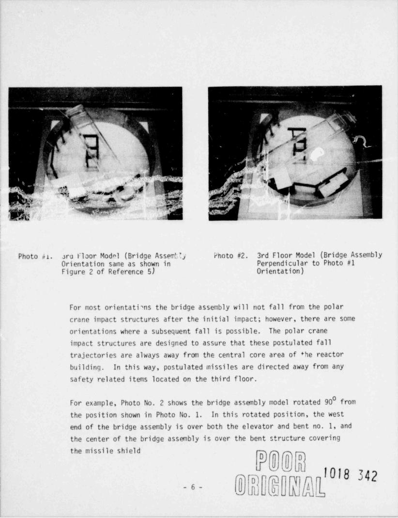
If derailment / dislocation is postulated, one end of the polar crane bridgecould lose support and drop until it impacts one of the polar crane impactstructures, the 3rd floor elevator structure, or both. Because of thevarious configurations in which dislocation could be postulated, a scalemodel of the third floor area was constructed to carefully examine thereaction of the polar crane bridge assembly. Photo No. 1 shows the model
as depicted in Figure 2 of Reference 5. The four structural bents (whichcomprise the polar crane impact structures), the elevator structure, thebridge crane and trolley are shown.
-5-
1018 341
+_
' '"i 1 ' ?4
.p L,
& ' /y',
c
b, 4 -1 '
. ,b , ' . i p'
m
h;i .%. . . ,,
* FJ
h~^ 6 # V [$:
. k},;h?<.,
' - f =m ',.
. L 4' [ y! ( '_. 'p igh4, . .: , ,
7| ~ ?&P!:,$ ;E ' ' r; "~'| '%Wj'l ]
f ^| .%qqp~ ^tQ .i.-
,
. - .
.- .-.~, a,-
..i .2 u.t '--
Photo h. ara Floor Model (Bridge AsseCy Photo #2. 3rd Floor Model (Bridge AssemblyOrientation same as shown in Perpendicular to Photo #1Figure 2 of Reference 5) Orientation)
For most orientati?ns the bridge assembly will not fall from the polarcrane impact structures after the initial impact; however, there are someorientations where a subsequent fall is possible. The polar craneimpact structures are designed to assure that these postulated falltrajectories are always away from the central core area of +he reactorbuilding. In this way, postulated missiles are directed away from anysafety related items located on the third floor.
0For example, Photo No. 2 shows the bridge assembly model rotated 90 fromthe position shown in Photo No. 1. In this rotated position, the west
end of the bridge assembly is over both the elevator and bent no. 1, andthe center of the bridge assembly is over the bent structure coveringthe missile shield pp
oaJ1018 342* o' ~T
A- 6-a - _1 a

If the end of the bridge assembly over the elevator and. bent no. 1 ispostulated to derail and move radially outward, the opposite end of thebridge assembly could lose peripheral support causing at least one ofthe bridge girders to impact the missile shield bent. If the other bridge
girder did not make contact, the bridge assembly would then rotate cwayfrom the central core area as shown in Photo No. 3. The loads imposed onthe missile shield bent because of the fecegoing postulated derailmentcase are of less consequence than the case selected for analysis initeference 5. For the derailment case discussed above, only half of thepolar crane bridge assembly impacts the bents, which produces significantlylower impact loading than the case considered in reference 5. Due to thestructural configuration of the missile shield bent, the loading associatedwith the case postulated above would cau*e lower stresses as compared tothe case analyzed in reference 5. Similarly, if an impact on the southbent is postulated, the resulting loadings and impact configurationswould be less critical than those considered in reisrence 5.
; , - 7"", T. M,z*-y . . ,
,,'^^y^ 3 . ,,.
'- ' 3 ';, .
3 ':1
%j- ;
,
,
' A;_
i--
51_
. m xxa
Photo #3. Resulting Bridge Position
D**Doo
D '9~I i010, 77,1Of
.k i l^ ~ '
a

Alternatively, if the end of the bridge assembly over the elevator ispostulated to derail and move radially inward, the end of the bridge cranewill impact bent i and the elevator structure as shown in Photo No. 4.Again, this bent loading is of less consequence than the case consideredin reference 5. The effect on the elevator structure is analyzed inAppendix 1 of reference 5 and it is shwn therein that the postulatedimpact of the polar crane assembly can be taken by the elevator structurewithout excessive deformation.
m7 maq p mpy3a| ~ }";|e:
C _' g;'
|Y~
; p,."
'
_'1,(y ,||n:_ .;y.u
.
j--g 54
$ l!
i'p4. * 4
,'b.~ K>' ~ ,y,
%,[ g3 '7
ie
Photo #4. Postulated Dislocation of theBridge Over the Elevator & Bent 1
0k@0@M
S '@Ry$n0
W- J s]u l e in -b ,.,,.
-8-

Request No. 6
It appears that the polar crane can be in such a position that only oneof the bridge girders will impact the polar crane impact structure. Showthat the polar crane will not topple off the impact structure and thestructure will support the crane with only one bridge girder resting onthe supporting structure.
Response to Request'No. 6
The scale mocel of the GETR third floor area and polar crane bridgeassembly (discussed in the Response to Request No. 5) was constructed toinsure that loss of crane support in any orientation was fully examined.There are some orientations in which postulated dislocation and derailmentwould result in the impact of only one girder of the bridge assembly onthe bent system. In all cases of single girder impact, the third floor
model clearly demonstrates that all fall trajectories would be away fromthe central core area of the reactor building. Since all safety relateditems (Fuel Flooding System, Fuel Storage System, etc.) are located inthe central core area, a fall of the bridge crane would not impact ordamage safety related equipment.
-.
_g_
1018 749
Request No. 7
The elastic half space theory used to determine soil springs assumes thatthe foundation slab is rigidly welded to the elastic half space. Provideyour bases for using a fraction of the contact area for computing the soilsprings. In addition, discuss how the failure of portions of the embeddedstructure ( e.g., foundation walls) affects the elastic half space soilsprings developed to account for the embedment effects. Provide a justi-
fication for including the effects of total embedment, and discuss theaffects on the resulting structural responses if embedment effects werenot considered.
Response to Request No. 7
The elastic half-space theory used to determine soil springs employed forthe linear elastic analyses described in Ref. 1 assumes that the foundationslab is rigidly connected to the elastic half space. On the basis ofpreliminary calculations, it was found that when subjected to a high magnitudeearthquake, the reactor building could undergo small rocking oscillationswith computed soil pressures falling to zero or near zero on portions ofthe foundation slab, resulting in an effectively reduced area of contactbetween the foundation slab and the underlying soil. This area of contactcould vary with time as the amplitude of earthquake motion varied.
For the linear elastic analyses described in Ref. 1, it was assumed thatthe average " effective" area of contact between the foundation slab andthe underlying soil would be 75 percent of the total area. This impliedthat at all times the area of contact between the foundation slab and theunderlying soil was 75 percent of the total area of contact, and this reducedarea was considered to be rigidly connected to the soil foundation.Detailed nonlinear analyses were performed using nonlinear models A' and B
(described in Ref. 1) to determine the influence on the structuralresponse of a potential reduction in the contact area between thefoundation slab and the underlying soil, and to validate the use of theassumed contact area (i.e., 75 percent). These nonlinear analyses showedthat the linear elastic analyses were conservative.
s
10 --
1018 T
.
The effects of embedment were included in the linear elastic analyses.The influence of the exclusion of embedment effects on the response ofthe reactor building structure was, however, investigated as part ofthe parametric studies. It was found, as discussed on page 2-9 ofReference 1, that with the complete exclusion of the embedment effects,the forces in the strenture could increase by approximately 10 to 12percent. However, it is unrealistic to assume that there would be noembedment effects at all. At the very least, partial embedment resistancewill always be present. The influence of the inclusion of such partialembedment effects (as compared to the total embedment effects) on theresponse of the reactor building structure would be less than about5 percent and would therefore be negligible.
.
- 11 -
1018 347

. .
Request No. 8
Recent tests conducted by PCA (" Tests to Evaluate Coefficient of StaticFriction Between Steel and Concrete, February 1979") indicate that thecoefficient of friction between steel and concrete is lower then thevalue used in your analyses, and that the measured coefficient of frictionfor wet and dry concrete were different. Verify that the reactor buildii.3is stable and will not slide considering these reported friction values,and discuss the appropriateness of using the wet or dry values.
Response to Request No. 8
The recent tests conducted by Portland Cement Association (PCA), aspresented in Ref. 3, indicate that the coefficient of friction betweensteel and concrete varies between 0.57 to 0.7 for different levels ofnormal stress, as well as for wet and dry concrete. In the analysespresented in Table 2-9 of Ref. 1, a value of 0.7 was used for the
coefficient of friction between concrete and steel. If the lower valuesof the coefficient of friction obtained by PCA are used instead of avalue of 0.7, the conclusions do not change. With the use of lower PCAvalues of the coefficient of friction, "the sliding force available"
would still be smaller than the " sliding force required", and there wouldbe no sliding at the interior concrete-foundation slab interface. These
conclusions are valid for both wet and dry values of the coefficient offriction.
1018 348- 12

.
REFERENCES
1. Engineering Decision Analysis Company, Inc., " Seismic Analysis ofReactor Building. General Electric Test Reactor - Dh3% 9
EUAL-11/-21/.ud", prep & red for 6enerai u ectric Company, 1 June 19/8.~
2. United States Nuclear Regulatory Commission, Standard Review Plan3.7.2, June 1975.
3. Rabbat, B. G., and H. G. Russell, " Tests to Evaluate Coefficient ofStatic Friction Between Steel and Concrete," prepared by ConstructionTechnology Laboratories, Portland Cement Association, Skokie, Illinois,February 1979.
4. " Updated Response to NRC Order to Show Cause Dated 10-24-77", submittedby General Electric Company to the NRC on July 20, 1978.
5. " Structural Analysis of Third Floor Missile Impact System, GeneralElectric Test Reactor" - Structural Mechanics Associates, June 1978,by Dr. H. Durlofsky.
6. United States Nuclear Regulatory Commission, Regulatory Guide 1.122,September 1976.
7. General Electric Response to NRC Roauest for Additional Informationon the Phase II Report, dated 26 u_.y 1978.
8. General Electric Response to NRC Request for Additional Information,dated 5 September 1979.
1018 349.