DivofCapitalCityToolInc. · divofcapitalcitytoolinc. submittaldata transfer/supplypump duplexunits...
20
219 Hahn Drive Frankfort, KY 40601 Tele: 800.766.1233 Fax: 502.223.4629 www.websterfuelpumps.com Div of Capital City Tool Inc. SUBMITTAL DATA TRANSFER / SUPPLY PUMP DUPLEX UNITS SIMPLEX UNITS SPM-SPMB-SPMV PROJECT DATE ARCHITECT ENGINEER CONTRACTOR WEBSTER REPRESENTATIVE EQUIPMENT CONTENTS L002715:Layout 1 10/24/07 1:02 PM Page 1
Transcript of DivofCapitalCityToolInc. · divofcapitalcitytoolinc. submittaldata transfer/supplypump duplexunits...

219 Hahn DriveFrankfort, KY 40601Tele: 800.766.1233 Fax: 502.223.4629 www.websterfuelpumps.com
Div of Capital City Tool Inc.
SUBMITTAL DATATRANSFER / SUPPLY PUMP
DUPLEX UNITSSIMPLEX UNITS
SPM-SPMB-SPMV
PROJECT
DATE
ARCHITECT
ENGINEER
CONTRACTOR
WEBSTERREPRESENTATIVE
EQUIPMENT
CONTENTS
L002715:Layout 1 10/24/07 1:02 PM Page 1

TRANSFER / SUPPLY PUMP / SIMPLEX / DUPLEX UNITS SUBMITTAL DATA
DATAJOB NAME MODEL #
LOCATION SIMPLEX
CITY DUPLEX MANUAL
STATE ZIP DUPLEX AUTO.
PUMPTOTAL FIRING RATE GPH MAXIMUM HEAD _________________FEET
SUCTION: LIFT IN FEET FLOW GPH
VALVE ADJUST: PRESSURE RANGE MINIMUM ______ PSIMAXIMUM _______ PSI
MOTORHORSE POWER RPM WATTS
VOLTS PHASE HZ ENCLOSURE
ACCESSORIESCHECK VALVE VACUUM BREAKER
COMPOUND GAUGE OIL SAFETY VALVE
ELECTRIC ALTERNATOR MECHANICALALTERNATOR
COMMON DISCHARGE MANIFOLD WITH CHECK VALVE
OTHER
2
L002715:Layout 1 10/24/07 1:02 PM Page 2

DUPLEX SUPPLY UNITS
The SPM DUPLEX models consist of two pump/motor assemblies with a pre-piped, common discharge manifold.One pump/motor unit operates continuously, with the second providing backup service if the main pump fails.Either automatic (SPM-DA models) or manual (SPM-DM models) controls are available.
The duplex automatic series are designed specifically for buildings where a constant supply of oil must be assured:hospitals, apartment buildings, schools and other commercial/industrial buildings. The SPM-DAmodels consist oftwo identical supply pump and motor sets mounted on a rigid channel iron base. Central to the base is a pedestalwhich supports the control panel. On the side of the control panel is a selector switch that identifies either Pump #1or Pump #2 to serve as the lead pump set. The other pump set then automatically becomes to lag pump set.Should the lead pump lose pressure, for any reason, it will automatically be turned off and the lag pump turned on.Simultaneously, an audible alarm will be activated to notify as service person that a pressure failure has occurredand attention must be given to the SPM-DA unit. The control panel is equipped with a lead-lag switch to permitmanual alternation of the pumps to provide even wear on each pump.
The duplex manual series is designed for commercial and industrial structures where an oil supply is required onlyduring occupancy, and a qualified person is always present to perform the manual switching. It is not recommendedfor structures with water sprinkler systems that are unoccupied for long periods of time. The SPM-DM consists oftwo identical supply pump and motor sets mounted on a rigid channel iron base. Central to the base is a pedestalupon which is mounted a selector switch only. If the active pump set fails, it must manually be turned off and theinactive unit turned on.
Motors on standard pump sets are 1725 RPM, single phase 60 hertz units and must be specified for operation at115 or 230 AC volts. Single phase 50 hertz motors are available on special request. Special pump sets are alsoavailable with 1725 RPM, three phase 50 or 60 hertz motors. Contact the factory for information. Both frequencyof operation and AC voltage must be specified (230 or 460 AC volts).
Many other features are available such as oil spill pans under pump sets, indicator lights, pressure regulatingvalves, etc. Contact the factory at (502) 695-4400 for information on these features and others that may not belisted.
DUPLEX AUTOMATIC OPERATIONThe basic premise for the control of an automatic duplex system is that a faulty supply pump will not developadequate pressure to supply fuel oil. By continuously monitoring pressure and issuing an indication when adecrease in pressure occurs, it is able to switch from the lead pump, which has developed a fault, to the lag pump.
Pressure monitoring is accomplished by using a Honeywell® Pressuretrol model L404F having a variable pressurerange (10-150 psi) and a variable differential range (10-22 psi).
A three position “SELECTOR” switch mounted on the right side of the control panel is used to select “PUMP 1” or“PUMP 2” as the lead pump. Center position on the selector switch turns the control unit “OFF”. Just below theselector is a “TEST” push button. While the automatic duplex system is operating, pushing the test button will turnoff the lead pump and turn on the lag pump. At the same time an audible alarm signal is sounded. Switching theselector switch to the “OFF” position and then back to the original setting will restore the control back to its originaloperating condition.
3
L002715:Layout 1 10/24/07 1:02 PM Page 3

INITIAL SETUPBefore connecting the unit to main power, make sure the “SELECTOR” switch is in the “OFF” position. Set thePressuretrol “MAIN” scale (scale on the right hand side) to slightly less (about 5%) than expected designed pressureof the system, and the differential setting marked “DIFF” (scale on the left hand side) to the pressure difference youwould like the system to switch from lead pump to lag pump. An an example: the system has been designed to op-erate at 85 psi, set the main pressure at 80 psi. If the pressure should drop to 70 psi you wish the lead pump toswitch in the lag pump. Thus the differential pressure should be set at 10 psi (80 psi - 70 psi) = 10 psi.
Briefly turn on the system to check pump rotation (clockwise looking into the shaft), and set pump pressures atsystem designed levels.
Once the system has been set up, power connected and pump rotating verified, the system can be checked as fol-lows:
1. Turn on the system and allow the lead pump to run for several minutes. If in about 20 or 30 secondsafter turning the system on, the lead pump drops out, check pump pressure settings and Pressuretrol“MAIN” pressure setting. The Pressuretrol setting must be about 5% less than pump set pressure. Ifall pressures check, and the lead pump still drops out, lower the Pressuretrol setting another 5% andtry again. If condition still continues, contact the factory at (502) 695-4400.
2. After the system lead pump has run for several minutes push the “TEST” button. The lead pump shoulddrop out, lag pump turn on, and the audible alarm sound.
3. Reset the system by turning the selector switch to “OFF” and back to its previous setting. The samelead pump should be engaged. Allow to run for several minutes. Re-adjust pump pressure setting to20% below designed pressure. The lead pump should drop out, lag pump turn on and the audio alarmsound.
4. Turn off the system, set the proper pressures and turn the system back on. Your system should beproperly set.
ELECTRICAL POWER CONNECTIONSAbide by all local electrical wiring codes in wiring the duplex systems.
Within the SPM-DA control box, at the bottom, just right of the Pressuretrol, is a terminal strip with ten terminals.The left most terminal is terminal one (1) and the right most terminal is terminal ten (10). For 115 AC volts, singlephase systems, power is applied to terminal one (1) and terminal two (2). For 220 AC volt, single phase systems,line 1 is applied to terminal one (1). The neutral line is applied to terminal two (2), and line 2 is applied to terminalten (10).
4
L002715:Layout 1 10/24/07 1:02 PM Page 4

SPM Single Supply Units
5
L002715:Layout 1 10/24/07 1:02 PM Page 5

SPM Duplex Automatic Models
SPECIFICATIONS
SPM Duplex Automatic units consist of two SPMSeries Pump/Motor assemblies and an electricalcontrol panel. They are designed for use in maintainedpressure supply systems only. If system pressure fallsbelow a preset level, the control automatically switchesfrom the primary pump/motor unit to the secondaryunit. If the backup pump/motor unit also fails to reachor maintain preset system pressure, the control alsoshuts off the backup unit.
A pump selector switch allows the two pump/motorunits to be manually alternated for even wear on eachpump. Pump pressures can be set at a range from 20PSI to 85 PSI. See Correct Supply Line Size charts formaximum discharge head.
TANK TO PUMP CONNECTIONS
Units should be set for two pipe operation. Preferredinstallation calls for a separate suction line from tank topump for each pump/motor unit. If system failure
occurs because of a gross leak in the suction line ofthe primary unit, the second unit can still providebackup service.
The correct suction line size can be determined byreferring to the line sizing charts. Generally, the returnline should be sized the same as the suction line. Lowpressure drop, swing type check valves can beinstalled in the suction lines, assuring that pumps arefull of oil, ready for service. Check valves in returnlines allow removal of inactive pump for servicing. Useof shutoff valves in return lines is not recommended.Be certain all plugs and connections are secureand leak-tight.
6
L002715:Layout 1 10/24/07 1:02 PM Page 6

SPECIFICATIONS SPM-15 / SPM-30 / SPM-65 / SPM-135CAPACITIES: 15, 30, 65, and 135 GPH.
PRESSURE: Maximum operating pressure to 80 PSI or 200’ of head.
MOTORS: All motors are 60 HERTZ, 1725 RPM, continuous duty.1/6, 1/4, 1/3 HP: SPLIT PHASE, 115 OR 230 VOLT operation1/2 HP: Capacitor start / induction run, TEFC, DUAL 115/230 VOLTMotors are clockwise as viewed from motor shaft end.50 HERTZ and/or 3 PHASE motors are available upon request.
PUMPS: SPM 15, 35, AND 65 USES WEBSTER “2R” SERIES PUMP UNITSSPM 135 USES WEBSTER “2V” SERIES PUMP UNITSWEBSTER 2R AND 2V ARE UL LISTED
PORTING: SPM15, 30, 65: 1/4” NPTF - 2 INLETS,OUTLETPORTANDTOPANDBOTTOMRETURNSSPM 135: 1/4” NPTF - OUTLET PORT
3/8” NPTF - RETURN PORT, 2 OPTIONAL INLETS1/2” NPTF - INLET
SEAL: All models - Double lip type. BUNA N. VITON available upon request.
MOUNTING: All models - Four bolt foot mount.
FILTER: Rotary self cleaning type, except in SPM 135. Use of external line filter recommended.For additional filter requirements, contact the factory.
VALVES: Pressure regulating assembly in pump maintains set pressure.Check valve maintains oil in feeder lines for instant starts.External regulators are required for flow rates higher than 135 GPH. Contact the factoryfor information.
GAUGE: 2 1/2” DIA., Calibrated from 30” of HG vacuum to 100 PSI.For other requirements, contact the factory.
INLET VACUUM: All units - 15” HG maximum.
NATIONAL FIRE PROTECTION ASSOCIATION COMPLIANCE REQUIRESFUEL INLET PRESSURE NOT TO EXCEED 3 PSIG.
CONTROLS: Duplex automatic with lead-lag switch, alarm, and push button test switch.Duplex manual with selector switch only.Additional controls are available. Contact the factory.
7
L002715:Layout 1 10/24/07 1:02 PM Page 7

SPM DUPLEX UNITS
SELECTION TABLE - SPM SERIES SIMPLEX / DUPLEX UNITS
WATTS SUCTION MAX OUTPUT TOTALMODELS MOTOR CONTROLS MOTOR @ PUMP CAPACITY FLOW @ FIRING BTU
VOLTAGE HP 85 PSI MODEL # GPH PSI, GPH1 RATE, GPH (MILLIONS)
SPM-15-1 120V SIMPLEXSPM-15-2 240V SIMPLEXSPM-15-X 3 PHASE SIMPLEXSPM-15-1-DA 115 AUTOMATICSPM-15-1-DM 115 MANUAL 1/6 65 2R181C-5BQ4 35 25 15 1.5SPM-15-2-DA 230 AUTOMATICSPM-15-2-DM 230 MANUALSPM-15-X-DA AUTOMATIC
3 PHASESPM-15-X-DM MANUAL
SPM-30-1 120V SIMPLEXSPM-30-2 240V SIMPLEXSPM-30-X 3 PHASE SIMPLEXSPM-30-1-DA 115 AUTOMATICSPM-30-1-DM 115 MANUAL 1/4 85 2R283C-5BQ4 70 45 30 3.0SPM-30-2-DA 230 AUTOMATICSPM-30-2-DM 230 MANUALSPM-30-X-DA AUTOMATIC
3 PHASESPM-30-X-DM MANUAL
SPM-65-1 120V SIMPLEXSPM-65-2 240V SIMPLEXSPM-65-X 3 PHASE SIMPLEXSPM-65-1-DA 115 AUTOMATICSPM-65-1-DM 115 MANUAL 1/3 175 2R686C-5BQ4125 90 65 6.5SPM-65-2-DA 230 AUTOMATICSPM-65-2-DM 230 MANUALSPM-65-X-DA AUTOMATIC
3 PHASESPM-65-X-DM MANUAL
SPM-135 SIMPLEXDUAL VOLTAGE
SPM-135-X 3 PHASESPM-135-DA 115 AUTOMATICSPM-135-DM 115 MANUAL 1/2 300 2V086C-5D020 250 167 135 13.5SPM-135-X-DA AUTOMATIC
3 PHASESPM-135-X-DM MANUAL
1FIRING RATE IN GPH @ 1725 RPM Pumping #2 fuel oil @75o F. Total firing rate is equal to the sum of burner firingrates, when burners are set for one-pipe operation as recommended. total must not exceed maximum rating shown.
For any additional requirements, contact the factory.
8
L002715:Layout 1 10/24/07 1:02 PM Page 8

SPM DUPLEXDIMENSIONS
SPM DUPLEX MANUAL SUPPLY UNIT
SPM DUPLEX AUTOMATIC UNIT
MODELS “A” PIPE THD SIZE
SPM-15-( )-DM 14.94 1/4
SPM-30-( )-DM 16.53 1/4
SPM-65-( )-DM 16.90 1/4
SPM-135-DM 21.37 3/8
MODELS “A” PIPE THD SIZE
SPM-15-( )-DA 14.94 1/4
SPM-30-( )-DA 16.53 1/4
SPM-65-( )-DA 16.90 1/4
SPM-135-DA 21.37 3/8
9
L002715:Layout 1 10/24/07 1:02 PM Page 9
SPMB Series Single and Duplex Supply Units
B series transfer pumps are designed to provide efficientpumping of #1 to #6 fuel oils, in capacities from 80 to 290gallons per hour, at pressures up to 500 PSI (except #1 oil).With high-density gray iron body construction, heat-treatedalloy steel gears and shafts, and special antifriction bearings.B series transfer pumps offer superior durability and high
mechanical efficiency. Double lip Viton seals, are standard.These pumps are also available in pump and motor pack-ages. Available in 115/230 volt single phase or 230/460 voltthree phase, simplex, duplex automatic and duplex manualconfigurations. All B series pumps are UL approved.
10
L002715:Layout 1 10/24/07 1:02 PM Page 10
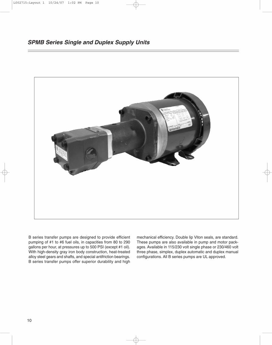
SPECIFICATIONS SPMB 18B-R / 37B-R / 47B-R / 59B-RCAPACITIES: 82, 159, 220, and 292 GPH.
PRESSURE: Maximum operating pressure to 80 PSI or 200’ of head.
MOTORS: All motors are 60 HERTZ, 1725 RPM, continuous duty.SPLIT PHASE, 115 OR 230 VOLT operation1/2 HP: Capacitor start / induction run, TEFC, DUAL 115/230 VOLTMotors are clockwise as viewed from motor shaft end.50 HERTZ and/or 3 PHASE motors are available upon request.
PUMPS: 18B-R, 37B-R, 47B-R, 59B-R
PORTING: 18B, 37B, 47B 1/2” NPTF side inlet and outlet59B 3/4” NPTF side inlet and outlet
SEAL: All models - Double lip type. VITON
MOUNTING: All models - Four bolt foot mount.
FILTER: Use of external line filter recommended.
VALVES: External pressure regulating or relief valve recommended.
GAUGE: 2 1/2” DIA., Calibrated from 30” of HG vacuum to 100 PSI.
INLET VACUUM: All units - 15” HG maximum.
NATIONAL FIRE PROTECTION ASSOCIATION COMPLIANCE REQUIRESFUEL INLET PRESSURE NOT TO EXCEED 3 PSIG.
CONTROLS: Duplex automatic with lead-lag switch, alarm, and push button test switch.Duplex manual with selector switch only.Additional controls are available. Contact the factory.
11
L002715:Layout 1 10/24/07 1:02 PM Page 11

MOTOR HORSEPOWER (1725 RPM STANDARD)
No. Description
25 .25 HP33 .33 HP50 .50 HP75 .75 HP100 1.0 HP150 1.5 HP200 2.0 HP300 3.0 HP
= only available in 115V or 230V single phase
MOTOR HORSEPOWER (1725 RPM STANDARD)Under pressure, read
horsepower required at 1750 RPMMaximum
Pump gph 25 100 200 300Model Nominal psi psi psi psiI
18BR 82 .25 .25 .25 .33
37BR 159 .25 .25 .50 .75
47BR 220 .25 .50 .75 1.00
59BR 292 .25 .50 .75 1.50
SPMB Duplex Ordering CodeWhen ordering SPMB Duplex models add suffix:
“DM,” for manual control models, or “DA,” forautomatic control models.
Example: SPMB-50AT/18BR-DA
Code Duplex Units
DM Duplex with manual controls
DA Duplex with automatic controls
MOTOR PHASE
Code Description
A Single Phase / 60 cycle / 115/208/230 VAC
B Three Phase / 60 cycle / 208 / 230 / 460 VAC
X Consult factory for other types
MOTOR ENCLOSURE
Code Description
T TEFC Std/ thru 2 HP
O OPDP Std. over 2 HP
SPMB Ordering Code
SPMB 50 A T 18BR DM1
1
2
3
4
5
2 3 4 5
When sizing SPMB units, remember that the pressures indi-cated are at the pump outlet.
All pumps relying on atmospheric pressure to push the fuel oilinto them are subject to cavitation. As fuel viscosity (thick-ness) increases, the tendency for cavitation becomes greater.Therefore, iti is best to mount the pump at the base of thetank and to use the largest diameter, shortest length, andstraightest inlet possible.
A large diameter inlet pipe or hose necked-down at the pumpis preferable to a longer lentth of similar diameter pipe be-cause the fuel tends to adhere to the inside of the pipe.
When initially starting a unit, it is desireable and sometimesnecessary to have a vent valve or plug on the pressure sideof the pump to facilitate its priming.
**
*
12
L002715:Layout 1 10/24/07 1:02 PM Page 12

SPMB Series Single and Duplex Supply Units
DC 4.5
D
A
B
DIMENSIONSMotor
NEMA
HP Fame Type A B C
Size (Standard)
.50 56C TEFC 9.00 8.25 9.20
.75 56C TEFC 9.00 8.25 9.20
1.00 56C TEFC 9.00 8.25 10.20
1.50 56C TEFC 9.00 8.25 11.20
2.00 56C TEFC 9.00 8.25 11.20
3.00 182TC OPDP 9.63 11.05 11.00
5.00 184TC OPDP 9.63 11.05 12.40
7.50 213TC OPDP 11.63 13.00 13.90
SPMBSINGLE SUPPLY UNIT
SPMBDUPLEX SUPPLY UNIT(Dimensions are for3 Phase DuplexAutomaticConsult Factoryfor Single PhaseDimensions)
Pump
Model E D
18BR 3.36 (.50HP) 17.06
37BR 3.71 (.75HP) 17.41
47BR 4.05 (.75HP) 17.75
59BR 4.40 (.75HP) 18.10
4.95”
13
L002715:Layout 1 10/24/07 1:02 PM Page 13
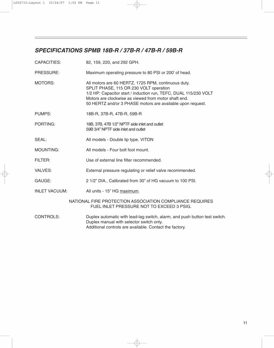
SPMV Series Single and Duplex Supply Units
Webster SPMV singe and duplex supply units aredesigned for high capacity applications where 430 to1790 GPH are required. Quite running, gear typepumps are aviailable in four sizes and incorporatedhardened integral shafts, journals and gears, specialanti-friction bearings. Buna-N seals, and cast irongear plates. Standard motors ranging from 1/2 hp to7.5 hp )373 w to 11.2 kw) are 1725 RPM NEMA “C”face, 115 volt single-phase or 230 volt three-phase,60 cycle type with TEFC enclosures through 2 hp(1490w) and OPDP enclosures over 2 hp (1490w).
Webster SPMV motor/pump high capacity fuel oilsupply units are designed to be used with fuels oilsincluding JP4. Fluid viscosities should not exceed6000 SUS. Suction should exceed 10” Hg. Inletpressures are rated at 34 PSI continously and 50 PSIfor short periods. The unit is designed to operatein -290 F to +2000 F conditions, depending on viscos-ity of oil. The motor is precision aligned and coupledto pump with machined adapter and flexible coupling.
SPECIFICATIONS
Capacity:430 to 1790 GPH with fluid viscosity to 10,000 SSU.
14
L002715:Layout 1 10/24/07 1:02 PM Page 14

SPECIFICATIONS SPMV 086K / 194K / 237K / 388KCAPACITIES: 439, 902, 1114, and 1730 GPH.
PRESSURE: Maximum operating pressure to 80 PSI or 200’ of head.
MOTORS: Standard 60 CY. 1725 RPM NEMA “C” face 1/2 through 15 HP available.Single Phase 115/208/230 VAC or Three Phase 208/230/460 VAC. TEFCare available.
PUMPS: 086K, 194K, 237K, 388K
PORTING: 086K-194K 1”NPTside inlet and outlet 237K-388K 1 1/2” x 1 1/4” NPT
SEAL: All models - Double lip type. VITON
MOUNTING: All models - Four bolt foot mount.
FILTER: Use of external line filter recommended.
VALVES: External pressure regulating or relief recommended.
GAUGE: 2 1/2” DIA., Calibrated from 30” of HG vacuum to 100 PSI.For other requirements, contact the factory.
INLET VACUUM: All units - 15” HG maximum.
NATIONAL FIRE PROTECTION ASSOCIATION COMPLIANCE REQUIRESFUEL INLET PRESSURE NOT TO EXCEED 3 PSIG.
CONTROLS: Duplex automatic with lead-lag switch, alarm, and push button test switch.Duplex manual with selector switch only.Additional controls are available. Contact the factory.
15
L002715:Layout 1 10/24/07 1:02 PM Page 15

SPMV Ordering Code
MOTOR HORSEPOWER (1725 RPM STANDARD)
No. Description
50 .50 HP75 .75 HP100 1.0 HP150 1.5 HP200 2.0 HP300 3.0 HP500 5.0 HP750 7.5 HP
= only available in 115V or 230V single phase
MOTOR HORSEPOWER (1725 RPM STANDARD)Under pressure, read
horsepower required at 1750 RPMMaximum
Pump gph 25 100 200 300Model Nominal psi psi psi psiI
086K 439 .50 .75 1.00 1.50
194K 902 1.00 1.75 2.50 3.00
237K 1114 1.00 2.00 3.00 4.00
388K 1791 2.00 3.50 4.50 6.00
SPMB Duplex Ordering CodeWhen ordering SPMV Duplex models add suffix:
“DM,” for manual control models, or “DA,” forautomatic control models.
Example: SPMV-50AT/086K-DA
Code Duplex Units
DM Duplex with manual controls
DA Duplex with automatic controls
MOTOR PHASE
Code Description
A Single Phase / 60 cycle / 115/208/230 VAC
B Three Phase / 60 cycle / 208 / 230 / 460 VAC
X Consult factory for other types
MOTOR ENCLOSURE
Code Description
T TEFC Std. thru 2 HP
O OPDP Std. over 2 HP
SPMV 50 A T 086K DM1
1
2
3
4
5
2 3 4 5
When sizing SPMV units, remember that the pressures indi-cated are at the pump outlet.
All pumps relying on atmospheric pressure to push the fuel oilinto them are subject to cavitation. As fuel viscosity (thick-ness) increases, the tendency for cavitation becomes greater.Therefore, it is best to mount the pump at the base of the tankand to use the largest diameter, shortest length, and straight-est inlet possible.
A large diameter inlet pipe or hose necked-down at the pumpis preferable to a longer lentth of similar diameter pipe be-cause the fuel tends to adhere to the inside of the pipe.
When initially starting a unit, it is desireable and sometimesnecessary to have a vent valve or plug on the pressure sideof the pump to facilitate its priming.
*
16
L002715:Layout 1 10/24/07 1:02 PM Page 16

DIMENSIONSMotor
NEMA
HP Fame Type A B C D
Size (Standard)
.50 56C TEFC 6.30 9.00 8.25 9.20
.75 56C TEFC 6.30 9.00 8.25 9.20
1.00 56C TEFC 6.30 9.00 8.25 10.20
1.50 56C TEFC 6.30 9.00 8.25 11.20
2.00 56C TEFC 6.30 9.00 8.25 11.20
3.00 182TC OPDP 7.30 9.63 11.05 11.00
5.00 184TC OPDP 7.30 9.63 11.05 12.40
7.50 213TC OPDP 8.00 11.63 13.00 13.90
F
Pump
Model E Minimum Maximum
086K 4.90 19.05 (.50HP) 20.85 (3.00HP)
194K 5.65 19.90 (.75HP) 23.10 (5.00HP)
237K 8.80 23.15 (.75HP) 27.85 (7.50HP)
388K 9.80 23.95 (.75HP) 28.65 (7.50HP)
SPMV Series Single and Duplex Supply Units
4.95”
17
L002715:Layout 1 10/24/07 1:02 PM Page 17
NOTES
18
L002715:Layout 1 10/24/07 1:02 PM Page 18

NOTES
19
L002715:Layout 1 10/24/07 1:02 PM Page 19

219 Hahn DriveFrankfort, KY 40601Tele: 800.766.1233 Fax: 502.223.4629 www.websterfuelpumps.com
Div of Capital City Tool Inc.
L002715:Layout 1 10/24/07 1:02 PM Page 20


![A reduced-precision streaming SpMV architecture for ... · A reduced-precision streaming SpMV architecture for Personalized PageRank on FPGA ... [11, 23] as real-world graphs present](https://static.fdocuments.us/doc/165x107/6049fa038fd34e46526c8245/a-reduced-precision-streaming-spmv-architecture-for-a-reduced-precision-streaming.jpg)