Directivity or Directive Gain -...
25
1 Directivity or Directive Gain Directivity or Directive Gain .
Transcript of Directivity or Directive Gain -...

1
Directivity or Directive GainDirectivity or Directive Gain
.
DirectivityDirectivity
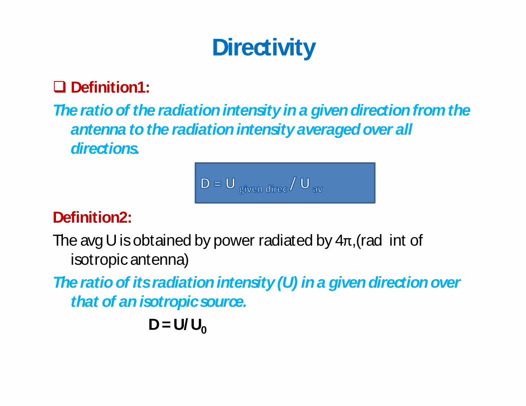
Definition1:
The ratio of the radiation intensity in a given direction from the antenna to the radiation intensity averaged over all directions.
Definition2:
The avg U is obtained by power radiated by 4π,(rad int of isotropic antenna)
The ratio of its radiation intensity (U) in a given direction over that of an isotropic source.
D = U/U0

Antenna DirectivityAntenna Directivity
• NOTE: D Has no units
4radavg PU
UUD
4 intensity radiation Average
sin),( radiatedpower Total
avg
0
2
0
rad
rad
PU
ddUP
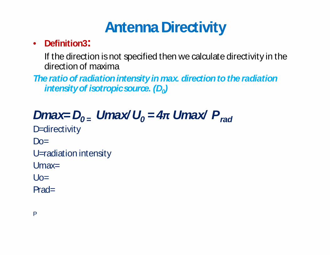
Antenna DirectivityAntenna Directivity• Definition3:
If the direction is not specified then we calculate directivity in the direction of maxima
The ratio of radiation intensity in max. direction to the radiation intensity of isotropic source. (D0)
Dmax= D0 = Umax/U0 = 4π Umax/ P radD=directivityDo=U=radiation intensityUmax=Uo=Prad=
P
Properties of D• D=1 for isotropic source
• D>1 for non isotropic
(max. directivity is greater than 1, Umax>Uo)
• D= 4π / ΩA
smaller the beam area………..
Antenna Radiation Efficiency
radcd
rad
in
radcd RR
RPPeK
/
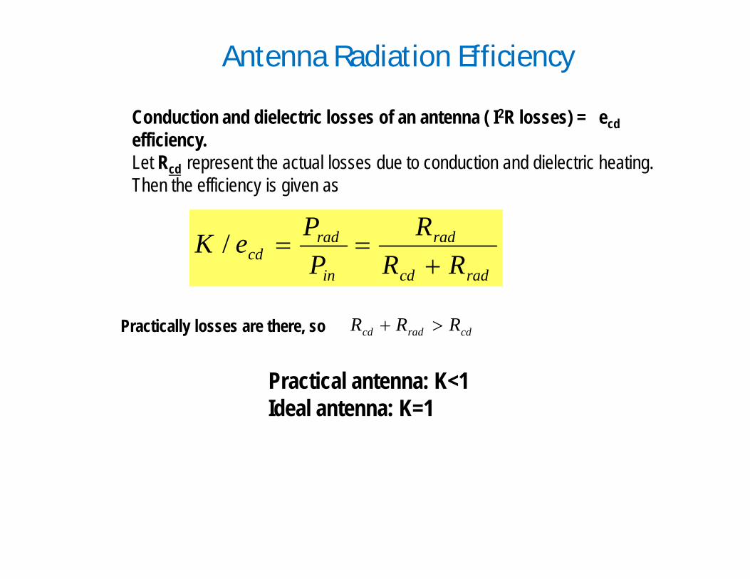
Conduction and dielectric losses of an antenna ( I2R losses) = ecdefficiency. Let Rcd represent the actual losses due to conduction and dielectric heating. Then the efficiency is given as
Practically losses are there, so cdradcd RRR
Practical antenna: K<1Ideal antenna: K=1
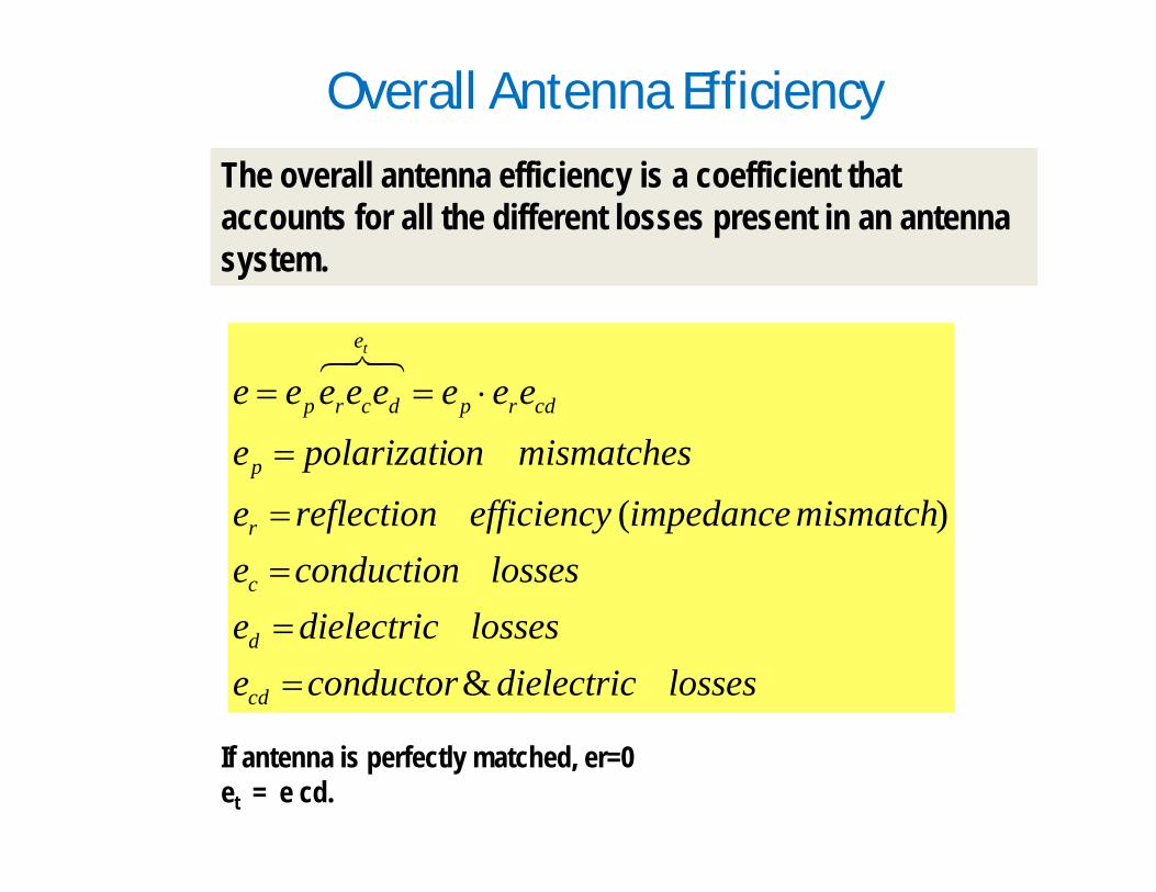
Overall Antenna Efficiency
The overall antenna efficiency is a coefficient that accounts for all the different losses present in an antenna system.
lossesdielectricconductorelossesdielectrice
lossesconductionemismatchimpedanceefficiencyreflectione
mismatchesonpolarizatieeeeeeeee
cd
d
c
r
p
cdrp
e
dcrp
t
&
)(
If antenna is perfectly matched, er=0et = e cd.
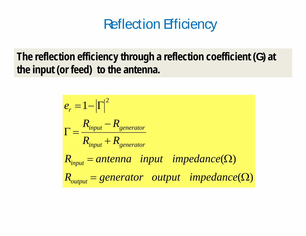
Reflection Efficiency
The reflection efficiency through a reflection coefficient (G) at the input (or feed) to the antenna.
)(
)(
1 2
impedanceoutputgeneratorRimpedanceinputantennaR
RRRR
e
output
input
generatorinput
generatorinput
r
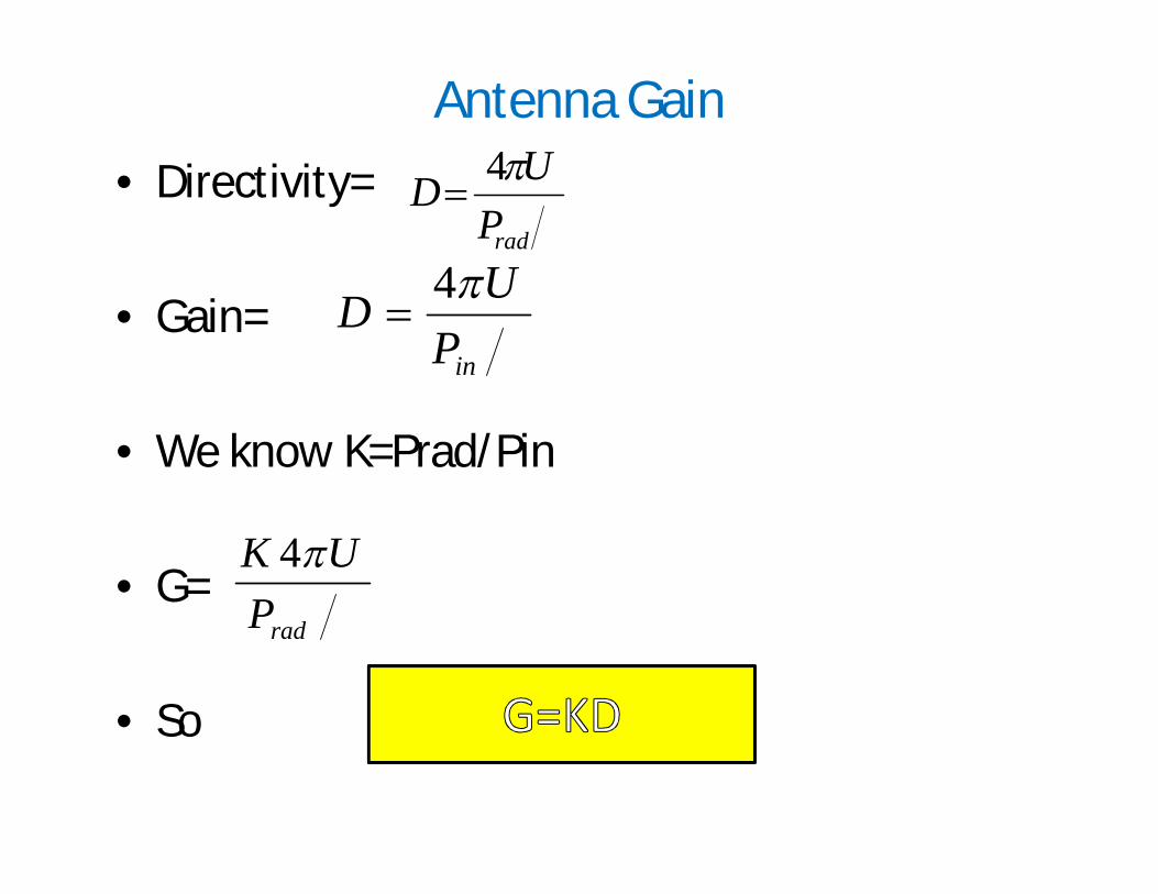
Antenna Gain
• Directivity=
• Gain=
• We know K=Prad/Pin
• G=
• So
radPUD 4
inPUD 4
radPUK 4
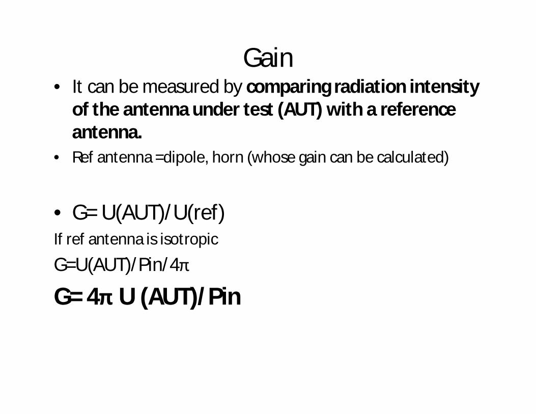
Gain• It can be measured by comparing radiation intensity
of the antenna under test (AUT) with a reference antenna.
• Ref antenna =dipole, horn (whose gain can be calculated)
• G= U(AUT)/U(ref)If ref antenna is isotropic
G=U(AUT)/Pin/4π
G= 4π U (AUT)/Pin

11
Antenna Gain
• The directivity and gain are measures of the ability of an antenna to concentrate power in a particular direction.
• Directivity – power radiated by antenna (P0 )
• Gain – power delivered to antenna (PT)
• K: radiation efficiency (50% - 75%)
• G has no units – Usually relates to the
peak directivity of the main radiation lobe
– Often expressed in dB– Known as “Absolute Gain”
or “Isotropic Gain”
in
rad
PPK
KDG
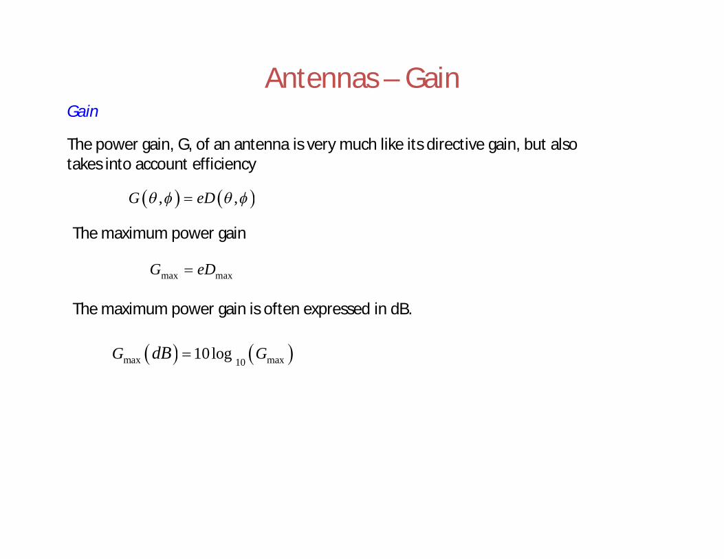
Antennas – GainGain
, ,G eD
The power gain, G, of an antenna is very much like its directive gain, but also takes into account efficiency
The maximum power gain
max maxG eD
The maximum power gain is often expressed in dB.
max max1010logG GdB
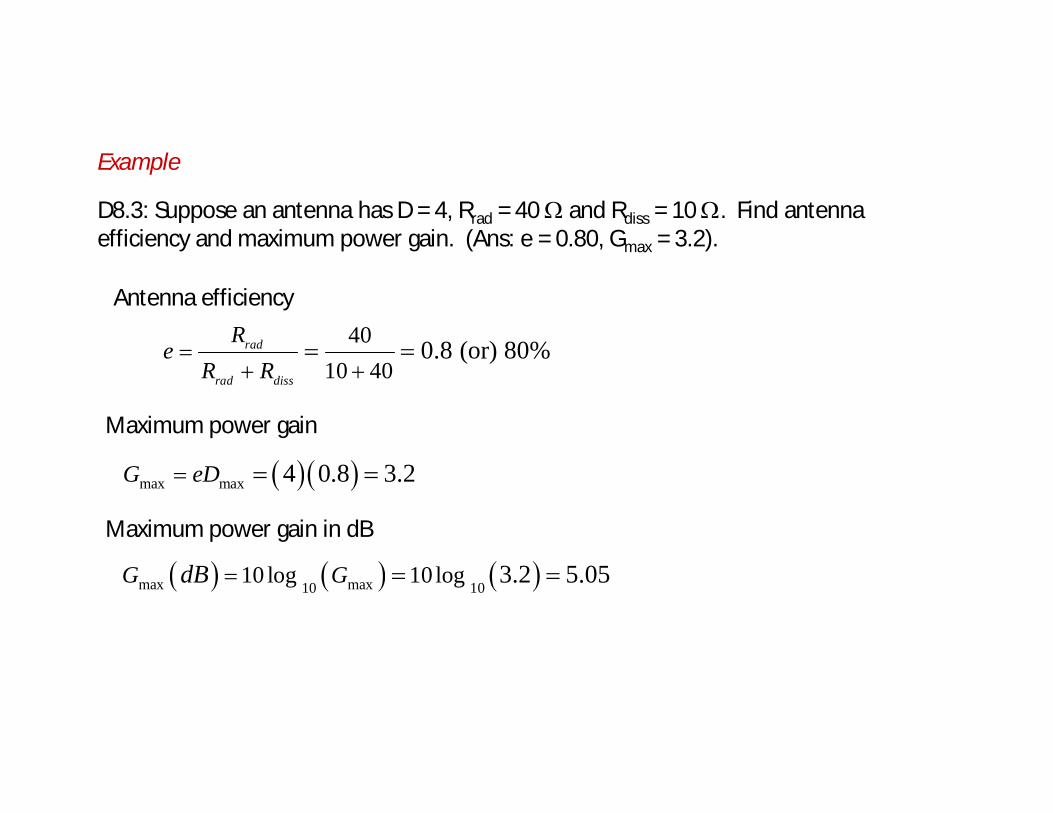
Example
D8.3: Suppose an antenna has D = 4, Rrad = 40 and Rdiss = 10 . Find antenna efficiency and maximum power gain. (Ans: e = 0.80, Gmax = 3.2).
4010 40
0.8 (or) 80%rad
rad diss
Re
R R
Antenna efficiency
Maximum power gain
max max 4 0.8 3.2G eD
max max10 1010 log 10log 3.2 5.05G GdB
Maximum power gain in dB
14
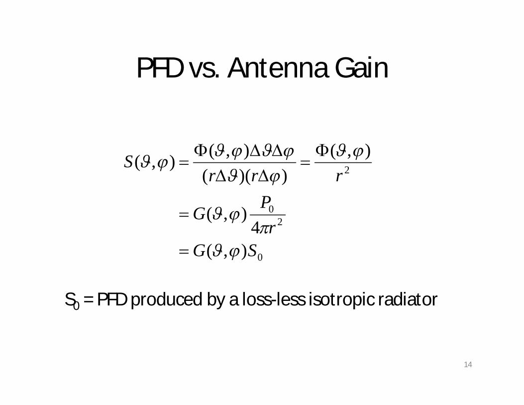
PFD vs. Antenna Gain
S0 = PFD produced by a loss-less isotropic radiator
0
20
2
),(4
),(
),())((
),(),(
SGr
PG
rrrS

15
Other Definitions of Gain
• For practical purposes, the antenna gain is defined as the ratio (usually in dB), of the power required at the input of a loss-free reference antenna to the power supplied to the input of the given antenna to produce, in a given direction, the same field strength or the same power flux-density at the same distance.
• When not specified otherwise, the gain refers to the direction of maximum radiation.
• The gain may be considered for a specified polarization. [RR 154]
16
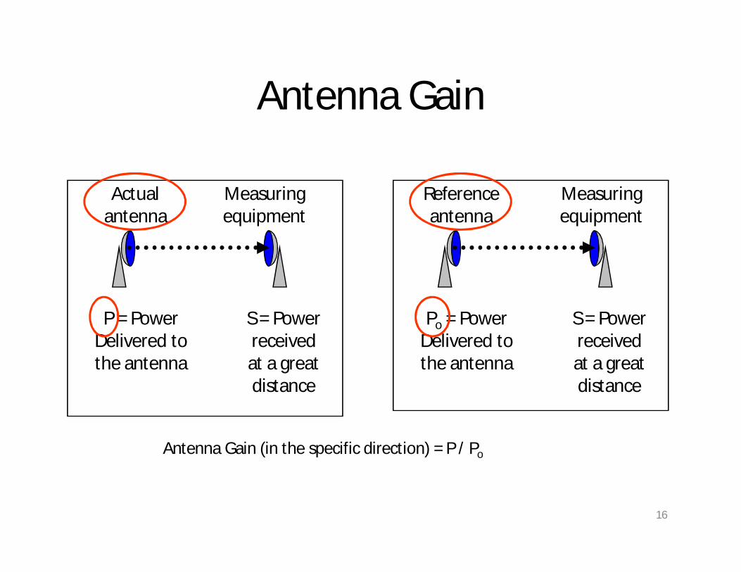
Antenna Gain
Actual antenna
P = Power Delivered to the antenna
S = Power receivedat a great distance
Measuring equipment
Reference antenna
Po = Power Delivered to the antenna
S = Power receivedat a great distance
Measuring equipment
Antenna Gain (in the specific direction) = P / Po
17
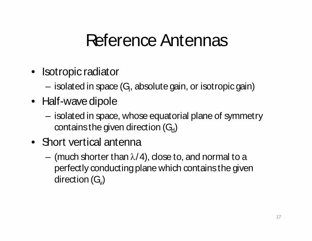
Reference Antennas
• Isotropic radiator – isolated in space (Gi, absolute gain, or isotropic gain)
• Half-wave dipole – isolated in space, whose equatorial plane of symmetry
contains the given direction (Gd)
• Short vertical antenna – (much shorter than /4), close to, and normal to a
perfectly conducting plane which contains the given direction (Gv)
18
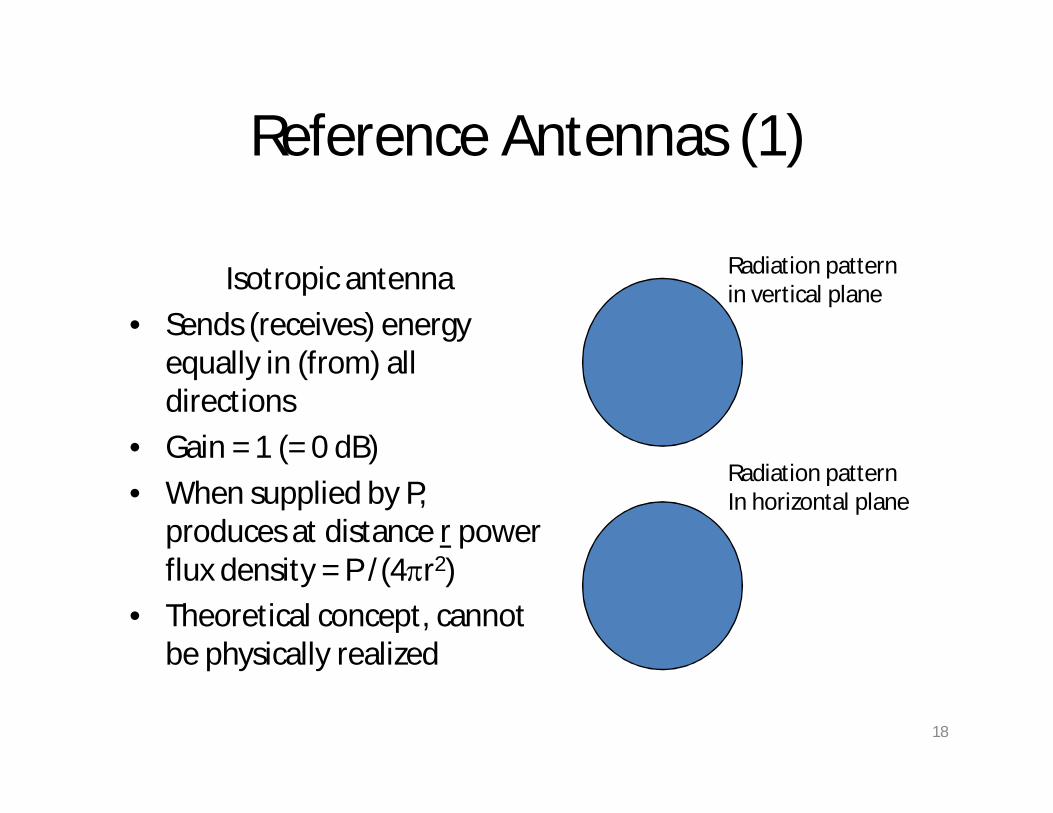
Reference Antennas (1)
Isotropic antenna
• Sends (receives) energy equally in (from) all directions
• Gain = 1 (= 0 dB)
• When supplied by P, produces at distance r power flux density = P /(4r2)
• Theoretical concept, cannot be physically realized
Radiation patternin vertical plane
Radiation patternIn horizontal plane

19
Reference Antennas (2)
Half-Wave Dipole
• Linear antenna, realizable
• Gain = 1.64 (= 2,15 dB) in the direction of maximum radiation
• Figure-eight-shaped radiation pattern in the dipole plane, omnidirectional (circular) in the orthogonal plan
Radiation patternin vertical plane
Radiation patternIn horizontal plane
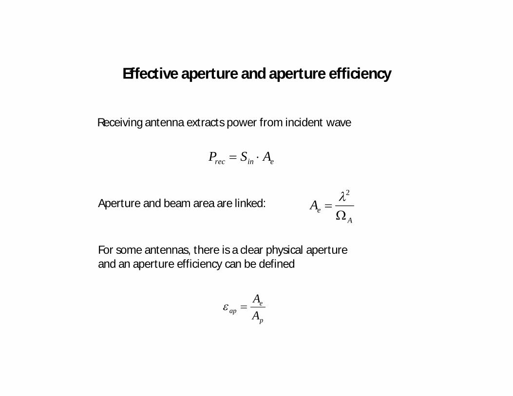
Effective aperture and aperture efficiency
Receiving antenna extracts power from incident wave
einrec ASP
For some antennas, there is a clear physical aperture and an aperture efficiency can be defined
p
eap A
A
AeA
2Aperture and beam area are linked:

Reciprocity
• Transmission and reception antennas can be used interchangeably
• Medium must be linear, passive and isotropic
• Caveat: Antennas are usually optimised for reception or transmission not both !
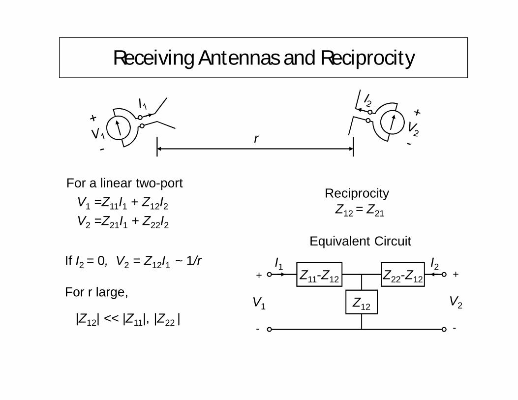
Receiving Antennas and Reciprocity
For a linear two-portV1 =Z11I1 + Z12I2V2 =Z21I1 + Z22I2
ReciprocityZ12 = Z21
If I2 = 0, V2 = Z12I1 ~ 1/r
For r large,
|Z12| << |Z11|, |Z22 |
r
Equivalent Circuit
Z11-Z12 Z22-Z12
Z12
+
V1
-
I1+
V2
-
I2
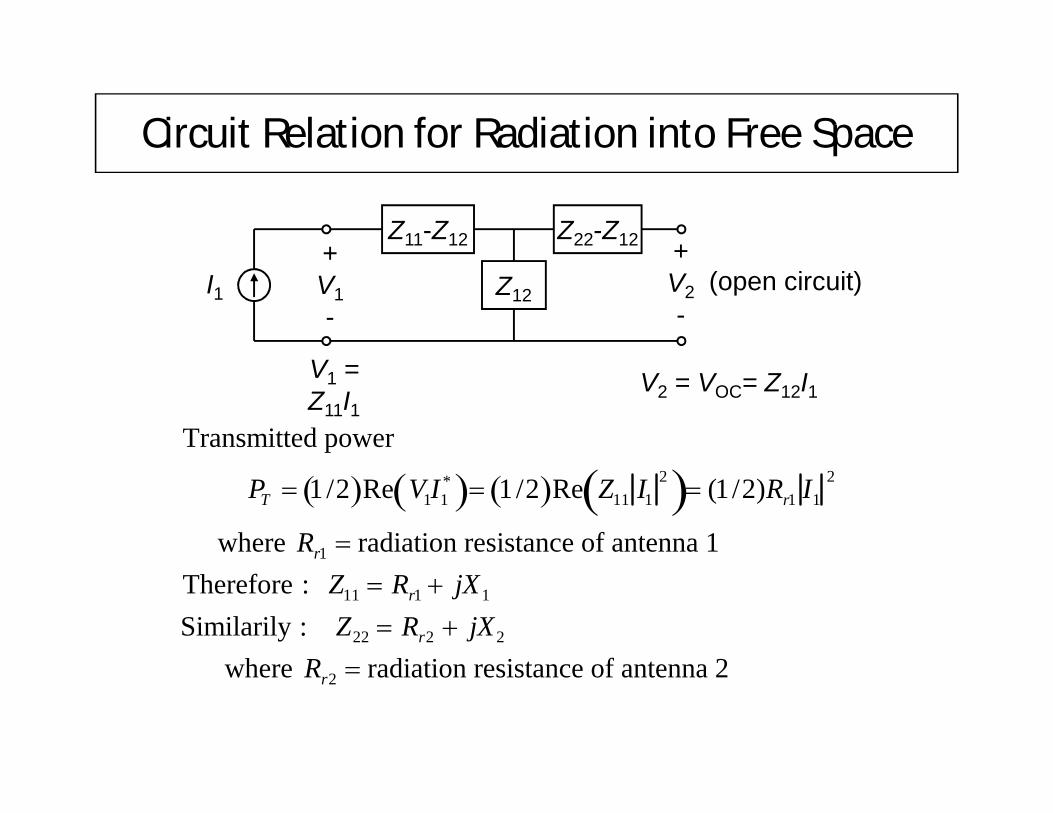
Circuit Relation for Radiation into Free Space
Z11-Z12 Z22-Z12
Z12
+V1-
I1+V2-
(open circuit)
V1 = Z11I1
V2 = VOC= Z12I1
Transmitted power
PT 1/2 Re V1I1* 1/2 Re Z11 I1
2 (1 /2)Rr1 I12
where Rr1 radiation resistance of antenna 1Therefore : Z11 Rr1 jX1
Similarily : Z22 Rr2 jX2
where Rr2 radiation resistance of antenna 2

Received Power and Path Loss RatioI2
Z11-Z12 Z22-Z12
Z22*+V1-
I1+V2-
Z12
+
-
Matched LoadRr2 - jX2
V
Current I1 divides between branches: I2 = -I1
Z12
Z12 Z 22Z 12Z22 -I1
Z12
2Rr 2
Received Power for Matched Load PR 12 I2
2Rr 2
12
I1Z12
2Rr 2
2
I12 Z12
2
8Rr 2
Path Gain PG PRPT
I1
2 Z122 8Rr 2
I12 Rr1 2
Z 12
2
4Rr1Rr 2
Final expression for PG is the same if antenna 2 radiates and antenna 1 receives.
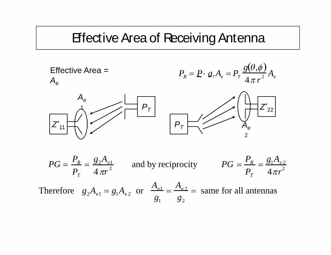
Effective Area of Receiving Antenna
Effective Area = Ae
PR P ar Ae PTg , 4 r 2 Ae
PT
Z*11
Ae1 Z*
22
PT Ae2
PG PR
PT
g2Ae1
4r 2 and by reciprocity PG PR
PT
g1Ae 2
4r2
Therefore g2Ae1 g1Ae 2 or Ae1
g1
Ae 2
g2
same for all antennas