Lecture 2 Error Detection & Correction -...
48
Lecture 2 Error Detection & Correction • Types of Errors • Detection • Correction
Transcript of Lecture 2 Error Detection & Correction -...
Lecture 2
Error Detection & Correction
• Types of Errors
• Detection
• Correction

Basic concepts
Networks must be able to transfer data from
one device to another with complete accuracy.
Data can be corrupted during transmission.
For reliable communication, errors must be
detected and corrected.
Error detection and correction
are implemented either at the data link layer or the transport layer of the OSI model.

Sources of errors
– a)Electromagnetic distortion of signal:
“noise” on the line.
– b)Error in sampling pulse relative to
neighbor pulse: “inter-symbol
interference”
– c)Energy coupling due to nearby links:
“cross-talk”.
– d)The storage of information on the
magnetic devices is prone to errors due to
uneven magnetic surface, dust etc.

Types of Errors

Single-bit error

Single bit errors are the least likely type of errors in serial data transmission because the noise must have a very short duration which is very rare. However this kind of errors can happen in parallel transmission.
Example:
If data is sent at 1Mbps then each bit lasts only 1/1,000,000 sec. or 1 μs.
For a single-bit error to occur, the noise must have a duration of only 1 μs, which is very rare.

Burst error


The term burst error means that two or
more bits in the data unit have changed
from 1 to 0 or from 0 to 1.
Burst errors does not necessarily mean that
the errors occur in consecutive bits, the
length of the burst is measured from the first
corrupted bit to the last corrupted bit. Some
bits in between may not have been
corrupted.

Burst error is most likely to happen in serial
transmission since the duration of noise is
normally longer than the duration of a bit.
The number of bits affected depends on the data
rate and duration of noise.
Example:
If data is sent at rate = 1Kbps then a noise of 1/100 sec
can affect 10 bits.(1/100*1000)
If same data is sent at rate = 1Mbps then a noise of
1/100 sec can affect 10,000 bits.(1/100*106)

ERROR DETECTING & ERROR CORRECTING CODES
To detect as well as correct these errors, various codes are present and these codes are:
(1) ERROR DETECTING CODES.
(2) ERROR CORRECTING CODES
The first type of code enables the device to detect errors which occur in the code of the bits and second type of code correct the errors automatically.
The various types of error detection and error correction techniques are closely related with the HAMMING DISTANCE between any two codes in the set of codes.

Error detection
Error detection means to decide whether the
received data is correct or not without having a
copy of the original message. In error detection
technique, it can only determine whether error has
occurred or not but it cannot correct it.
Error detection uses the concept of redundancy,
which means adding extra bits for detecting
errors at the destination.

Redundancy

Four types of redundancy checks are used
in data communications

ERROR-DETECTING CODES
PARITY PARITY is the no. of ones present in the data whereas PARITY BIT is an extra bit (that may be 0 or 1) which may be added in the data for making the parity to be even or odd. The two different methods are used & they are: •EVEN PARITY METHOD. In this method, the value of parity bit is taken as 0 or 1 depending upon the total no. of 1's INCLUDING THE PARITY BIT to be even.
•ODD PARITY METHOD.
This method is similar to the even parity technique such that total no. of 1's INCLUDING THE PARITY BIT would be odd.
For detection of error an extra bit known as parity bit is attached to each code word to make the no. of ones in the code even(even parity) or odd(odd parity).

ERROR-DETECTING
CODES BCD code with even & odd parities are shown in the table below BCD code with the parity bit
BCD code BCD code with even parity BCD code with odd parity
D C B A P D C B A P D C B A 0 0 0 0 0 0 0 0 0 1 0 0 0 0 0 0 0 1 1 0 0 0 1 0 0 0 0 1 0 0 1 0 1 0 0 1 0 0 0 0 1 0 0 0 1 1 0 0 0 1 1 1 0 0 1 1 0 1 0 0 1 0 1 0 0 0 0 1 0 0 0 1 0 1 0 0 1 0 1 1 0 1 0 1 0 1 1 0 0 0 1 1 0 1 0 1 1 0 0 1 1 1 1 0 1 1 1 0 0 1 1 1 0 0 0 0 1 1 0 0 0 0 1 0 0 0 0 0 1 0 0 1 0 0 1 1 1 0 0 1

Error detection: Parity

Vertical Redundancy Check
VRC

Performance
It can detect single bit error
It can detect burst errors only if the total
number of errors is odd.

Longitudinal Redundancy Check
LRC

Performance
LRC increases the likelihood of detecting
burst errors.
If two bits in one data units are damaged
and two bits in exactly the same positions in
another data unit are also damaged, the LRC
checker will not detect an error.

VRC and LRC

Cyclic Redundancy Check
CRC

Cyclic Redundancy Check
• Given a k-bit frame or message, the transmitter generates an n-bit sequence, known as a frame check sequence (FCS), so that the resulting frame, consisting of (k+n) bits, is exactly divisible by some predetermined number.
• The receiver then divides the incoming frame by the same number and, if there is no remainder, assumes that there was no error.

Binary Division

Polynomial

Polynomial and Divisor

Standard Polynomials

CHECKSUM METHOD The PARITY METHOD will not work when even no. of changes occur because the even error will not change the oddness & evenness of the total no. of 1's in the code. Thus, to avoid this CHECKSUM METHOD is used as each data to be transmitted is added to the previous one & sum is retained at the sending end. At the end of transmission, the total sum known as checksum is sent and is checked at the receiving point.

Checksum

At the sender
The unit is divided into k sections, each of n
bits.
All sections are added together using one’s
complement to get the sum.
The sum is complemented and becomes the
checksum.
The checksum is sent with the data

At the receiver
The unit is divided into k sections, each of n
bits.
All sections are added together using one’s
complement to get the sum.
The sum is complemented.
If the result is zero, the data are accepted:
otherwise, they are rejected.

Performance
The checksum detects all errors involving an
odd number of bits.
It detects most errors involving an even number
of bits.
If one or more bits of a segment are damaged
and the corresponding bit or bits of opposite
value in a second segment are also damaged, the
sums of those columns will not change and the
receiver will not detect a problem.

Error Correction
It can be handled in two ways:
1) receiver can have the sender retransmit the
entire data unit.
2) The receiver can use an error-correcting
code, which automatically corrects certain
errors.

Single-bit error correction To correct an error, the receiver reverses the value
of the altered bit. To do so, it must know which bit
is in error.
Number of redundancy bits needed
• Let data bits = m
• Redundancy bits = r
Total message sent = m+r
The value of r must satisfy the following relation:
2r ≥ m+r+1

Error Correction

Hamming Codes
HAMMING CODE : is constructed by adding a no. of parity bits to each group of n-bit information, or message in such a way so as to be able to locate the bit position in which error occurs. Values (0 or 1) are assigned to the parity bits so as to make the hamming code have either even parity or odd parity & when an error occurs, the position no. will take on the value assigned to the location of the erroneous bit.

Hamming Code

Hamming Codes
Hamming Codes Construction for 1-bit error-correcting codes Minimal number of check bits required Construction number bits from 1 upward powers of 2 are check bits all others are data bits Check bit j is XOR of all bits k such that (j AND k) = j
Example: 4 bits of data, 3 check bits
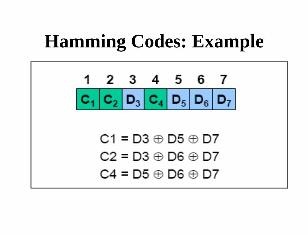
Hamming Codes: Example

Hamming Codes: Example

Hamming Codes: Example For example
A hamming code 0110001 is being received. Find the correct code which is being transmitted.
SOLUTION: 001 010 011 100 101 110 111
1 2 3 4 5 6 7
P1 P2 D1 P3 D2 D3 D4
0 1 1 0 0 0 1
P1 = 1 , 3 , 5, 7
P2 = 2 , 3 ,6 , 7
P3 = 4 , 5 , 6 ,7
Checksum Bits:
C1 = 0
C2 = 1
C3 = 1
In reverse order, 110.
Therefore, error has occurred at position 6.
Hence, the exact code transmitted is: 0110011.

ERROR DETECTING & ERROR CORRECTING
CODES
(Conclusion) 1.These codes help us to trace out the errors in the digital data and to correct that
error.
2.There are many types of codes for error detection and correction e.g. parity bit
is a kind of error detection code that can find only one bit error
in the data.
3. Hamming code is an error detection and correction code.
4. These codes are used in detecting and correcting error in the transmitted
digital data and it helps in the error free transmission of the data.

Hamming Code

Hamming Code

Example of Hamming Code

Single-bit error

Error
Detection