Dimension Ing Standards
48
Dimensioning Dimensioning Standards Standards
-
Upload
gontobbohin-asad -
Category
Documents
-
view
227 -
download
0
Transcript of Dimension Ing Standards
8/2/2019 Dimension Ing Standards
http://slidepdf.com/reader/full/dimension-ing-standards 1/48
Dimensioning Dimensioning
StandardsStandards
8/2/2019 Dimension Ing Standards
http://slidepdf.com/reader/full/dimension-ing-standards 2/48
Rules and Practices
Accurate dimensioning is one of the most
demanding undertakings when designing parts.
U se the checklist to insure you have followed the
basic dimensioning rules.
Keep in mind there may be a case where theneed to break a standard could occur to give
clarity to the part and manufacturer.
8/2/2019 Dimension Ing Standards
http://slidepdf.com/reader/full/dimension-ing-standards 3/48
Standards In order for the drawings to be dimensioned
so that all people can understand them, we
need to follow standards that every companyin the world must follow. Standards are
created by these organizations:
-ANSI -MIL
-ISO -DOD
-DIN -CEN
-JIS

8/2/2019 Dimension Ing Standards
http://slidepdf.com/reader/full/dimension-ing-standards 4/48
Standards Institutions
ANSI - American National Standards Institute
- This institute creates the engineering
standards for North America.
ISO - International Organization for
Standardization - This is a world wide
organization that creates engineeringstandards with approximately 100
participating countries.
8/2/2019 Dimension Ing Standards
http://slidepdf.com/reader/full/dimension-ing-standards 5/48
Standards Institutions
DIN - Deutsches Institut für Normung - The
German Standards Institute created many
standards used world wide such as the
standards for camera film.
JIS - Japanese Industrial Standard - Created
after WWII for Japanese standards.
CEN - European Standards Organization
8/2/2019 Dimension Ing Standards
http://slidepdf.com/reader/full/dimension-ing-standards 6/48
Standards Institutions
The United States military has two organizations
that develop standards.
DOD - Department Of Defense
MIL - Military Standard
8/2/2019 Dimension Ing Standards
http://slidepdf.com/reader/full/dimension-ing-standards 7/48
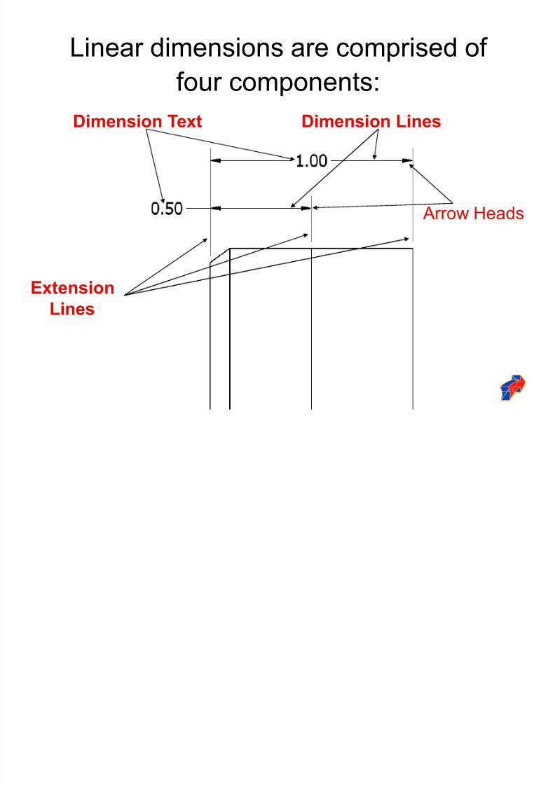
Linear dimensions are comprised of
four components:
ExtensionLines
Dimension Text Dimension Lines
Arrow Heads
8/2/2019 Dimension Ing Standards
http://slidepdf.com/reader/full/dimension-ing-standards 8/48
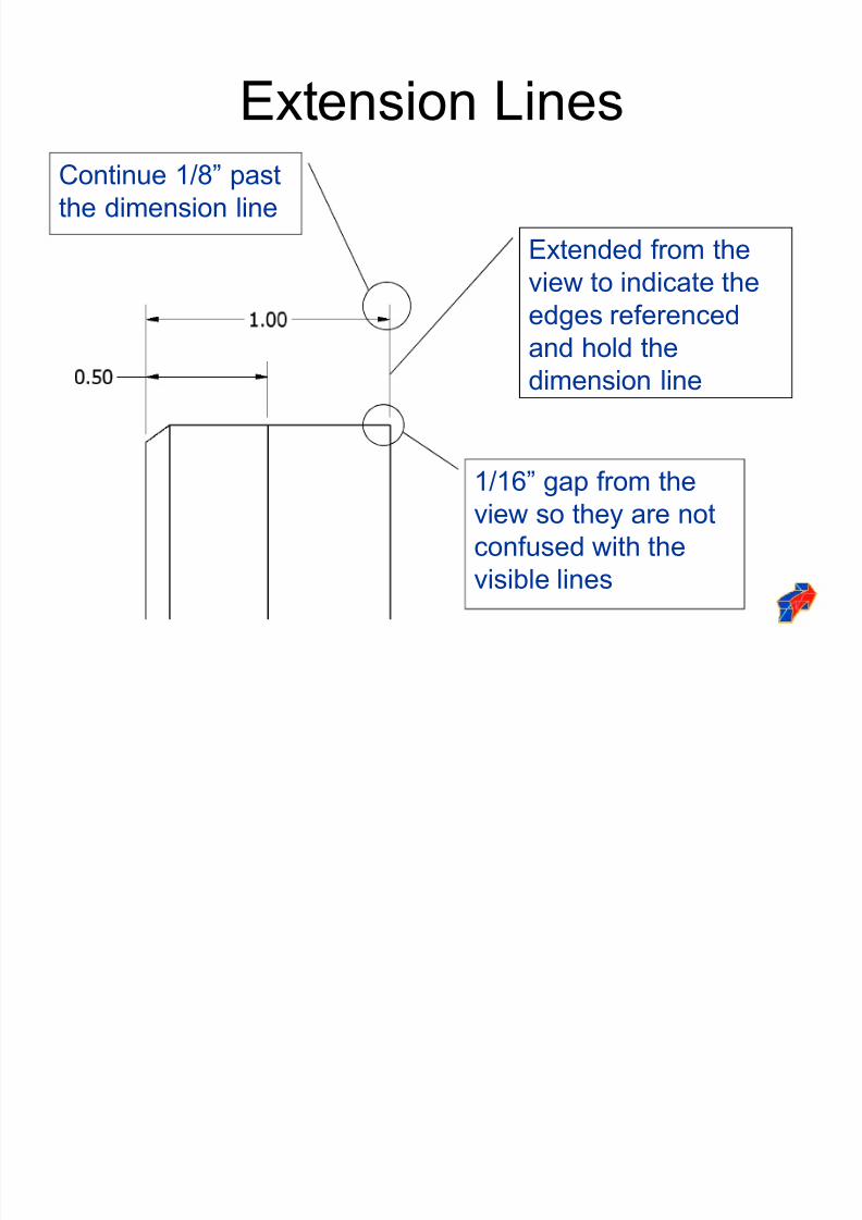
Extension Lines
Extended from the
view to indicate the
edges referenced
and hold the
dimension line
1/16´ gap from the
view so they are not
confused with the
visible lines
Continue 1/8´ past
the dimension line
8/2/2019 Dimension Ing Standards
http://slidepdf.com/reader/full/dimension-ing-standards 9/48
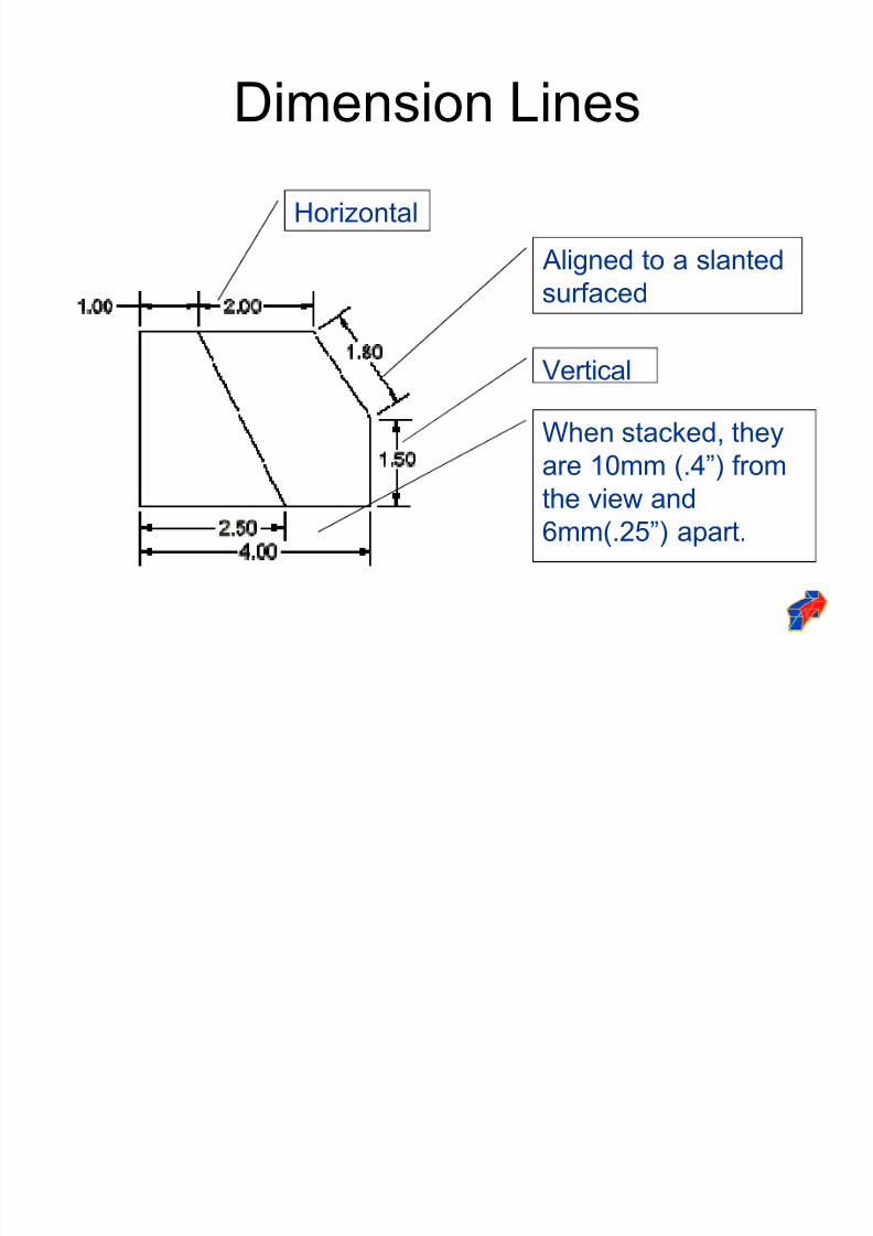
Dimension Lines
Horizontal
Aligned to a slanted
surfaced
Vertical
When stacked, they
are 10mm (.4´) fromthe view and
6mm(.25´) apart.
8/2/2019 Dimension Ing Standards
http://slidepdf.com/reader/full/dimension-ing-standards 10/48
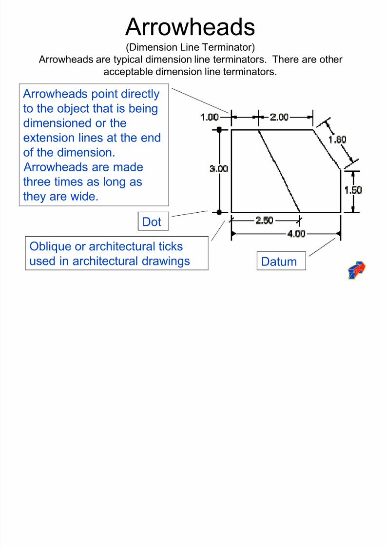
Arrowheads(Dimension Line Terminator)
Arrowheads are typical dimension line terminators. There are other
acceptable dimension line terminators.
Arrowheads point directly
to the object that is being
dimensioned or the
extension lines at the endof the dimension.
Arrowheads are made
three times as long as
they are wide.
Dot
Oblique or architectural ticks
used in architectural drawings Datum
8/2/2019 Dimension Ing Standards
http://slidepdf.com/reader/full/dimension-ing-standards 11/48
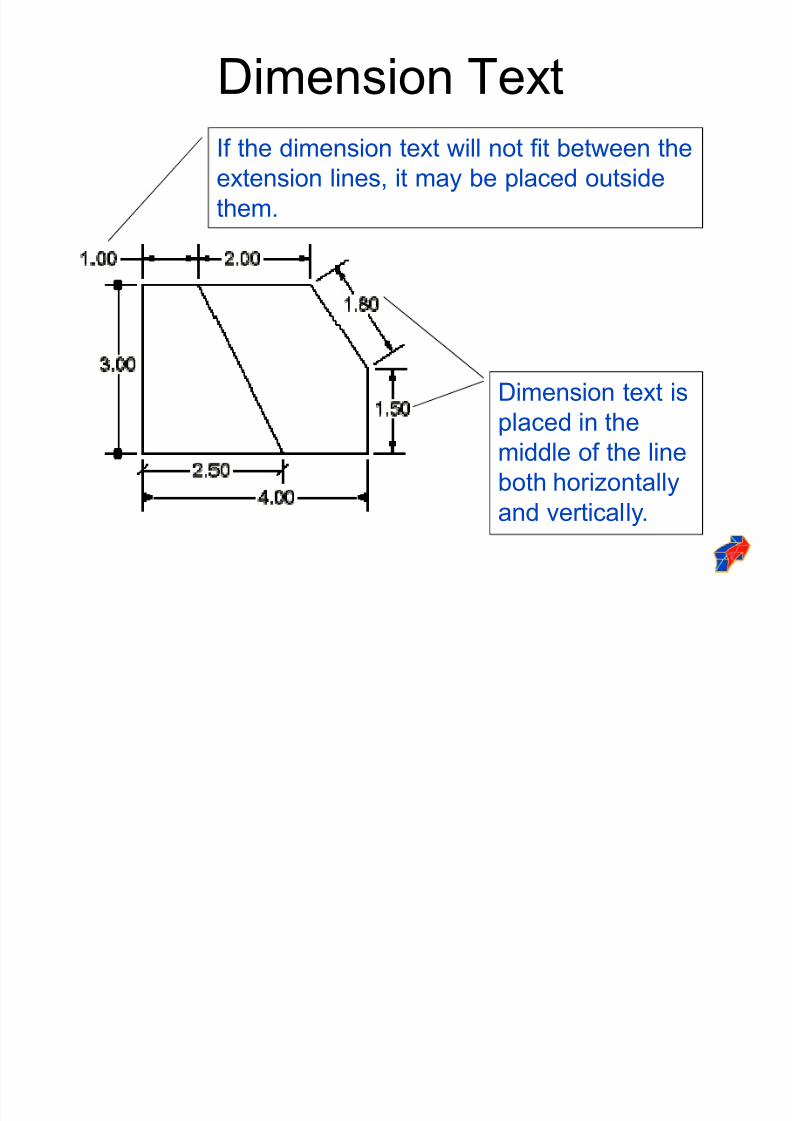
Dimension Text
Dimension text is
placed in themiddle of the line
both horizontally
and vertically.
If the dimension text will not fit between theextension lines, it may be placed outside
them.
8/2/2019 Dimension Ing Standards
http://slidepdf.com/reader/full/dimension-ing-standards 12/48
Dimensioning Methods
Dimensions are represented on a drawing using
one of two systems, unidirectional or aligned.
The unidirectional method means all dimensions
are read in the same direction.
The aligned method means the dimensions are
read in alignment with the dimension lines or
side of the part, some read horizontally andothers read vertically.
8/2/2019 Dimension Ing Standards
http://slidepdf.com/reader/full/dimension-ing-standards 13/48
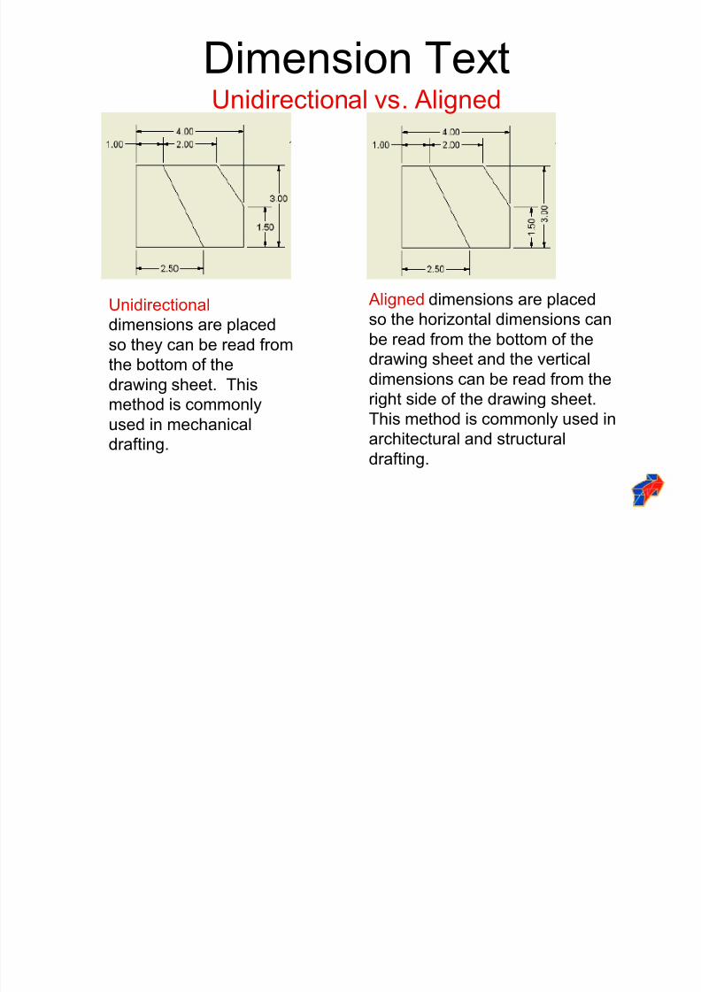
Dimension TextUnidirectional vs. Aligned
Unidirectional
dimensions are placed
so they can be read from
the bottom of thedrawing sheet. This
method is commonly
used in mechanical
drafting.
Aligned dimensions are placed
so the horizontal dimensions can
be read from the bottom of the
drawing sheet and the verticaldimensions can be read from the
right side of the drawing sheet.
This method is commonly used in
architectural and structural
drafting.
8/2/2019 Dimension Ing Standards
http://slidepdf.com/reader/full/dimension-ing-standards 14/48
Types of Dimensions
There are two classifications of dimensions: sizeand location.
Size dimensions are placed in directrelationship to a feature to identify the specificsize.
Location dimensions are used to identify the
relationship of a feature to another feature withinan object.
8/2/2019 Dimension Ing Standards
http://slidepdf.com/reader/full/dimension-ing-standards 15/48
Dimensioning Checklist Each dimension should be written clearly
with only one way to be interpreted.
A feature should be dimensioned only once.
Dimension and extension lines should not
cross.
Each feature should be dimensioned.
Dimension features or surfaces should be
done to a logical reference point.

8/2/2019 Dimension Ing Standards
http://slidepdf.com/reader/full/dimension-ing-standards 16/48
Dimension Checklist
Dimension circles should havediameters and arcs with a radius.
A center line should be extended andused as an extension line.
Dimension features on a view should
clearly show its true shape. Enough space should be provided to
avoid crowding and misinterpretation.
8/2/2019 Dimension Ing Standards
http://slidepdf.com/reader/full/dimension-ing-standards 17/48
Dimension Checklist
Extension lines and object lines
should not overlap.
Dimensions should be placed outsidethe part.
Center lines or marks should be used
on all circles and holes.
8/2/2019 Dimension Ing Standards
http://slidepdf.com/reader/full/dimension-ing-standards 18/48
Linear Dimensioning
Dimensioning from feature to featureis known as C hain Dimensioning.. Itis commonly used and easy to layout. It does have possibleconsequences in the manufacturingof a part. Tolerances can
accumulate, making the end productlarger or smaller than expected.
8/2/2019 Dimension Ing Standards
http://slidepdf.com/reader/full/dimension-ing-standards 19/48
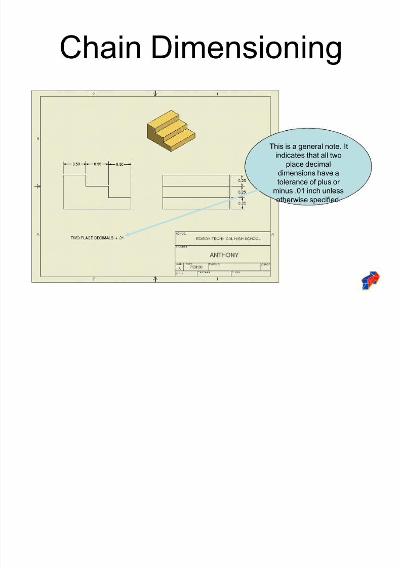
Chain Dimensioning
This is a general note. It
indicates that all two
place decimal
dimensions have a
tolerance of plus or
minus .01 inch unless
otherwise specified.
8/2/2019 Dimension Ing Standards
http://slidepdf.com/reader/full/dimension-ing-standards 20/48
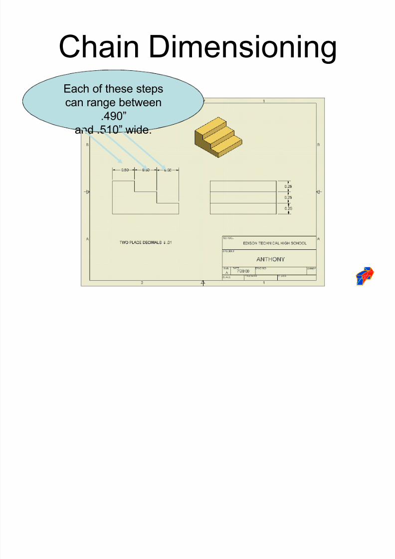
Chain DimensioningEach of these steps
can range between
.490´
and .510´ wide.
8/2/2019 Dimension Ing Standards
http://slidepdf.com/reader/full/dimension-ing-standards 21/48
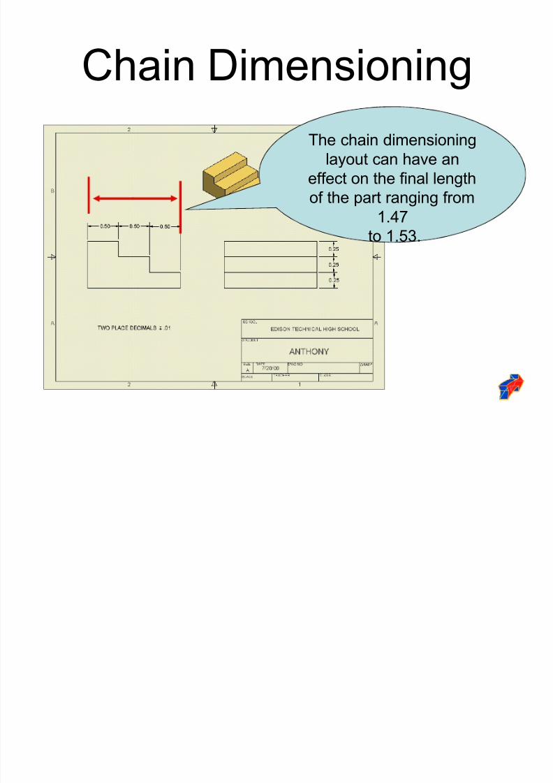
Chain Dimensioning
The chain dimensioning
layout can have an
effect on the final length
of the part ranging from1.47
to 1.53.
8/2/2019 Dimension Ing Standards
http://slidepdf.com/reader/full/dimension-ing-standards 22/48
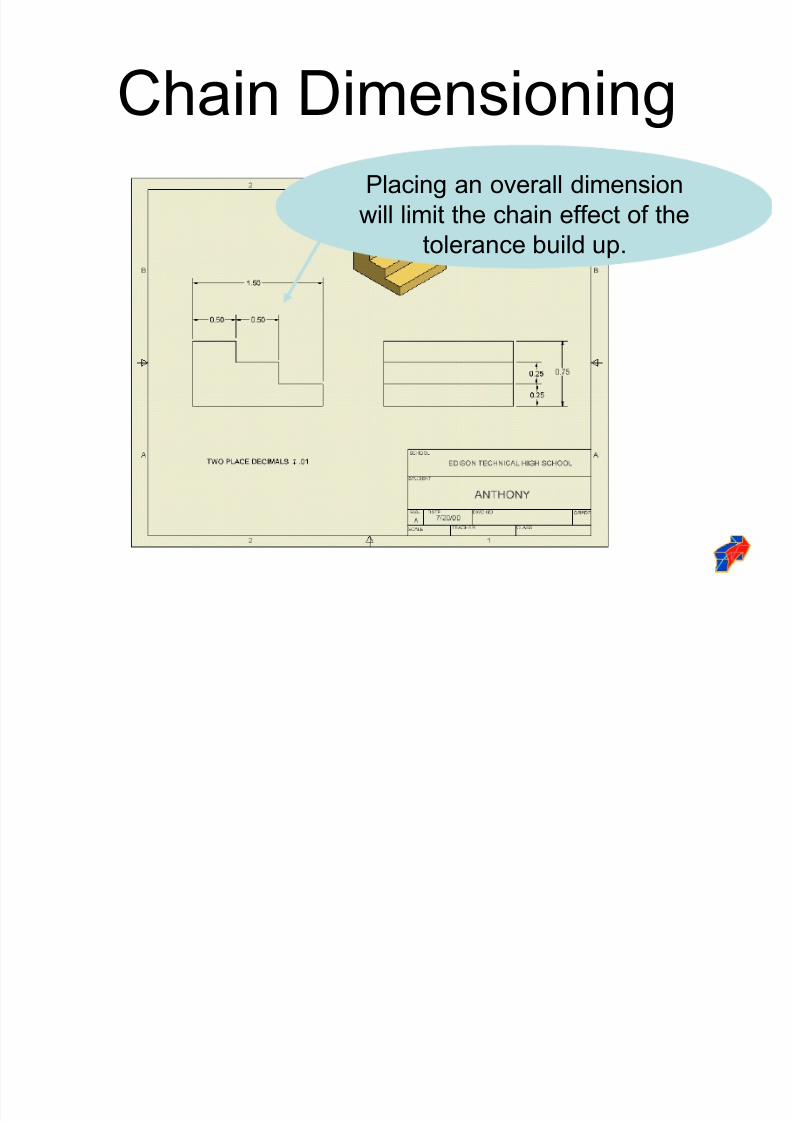
Chain Dimensioning
Placing an overall dimension
will limit the chain effect of the
tolerance build up.
8/2/2019 Dimension Ing Standards
http://slidepdf.com/reader/full/dimension-ing-standards 23/48
Linear Dimensioning
The accuracy of the final product is
determined by the dimensions on the
drawing. If all the dimensions originate
from a common corner of the part, the
object will be more accurate. This is
referred to as Datum Dimensioning.
Datums insure the tolerance or errors inmanufacturing do not accumulate.
8/2/2019 Dimension Ing Standards
http://slidepdf.com/reader/full/dimension-ing-standards 24/48
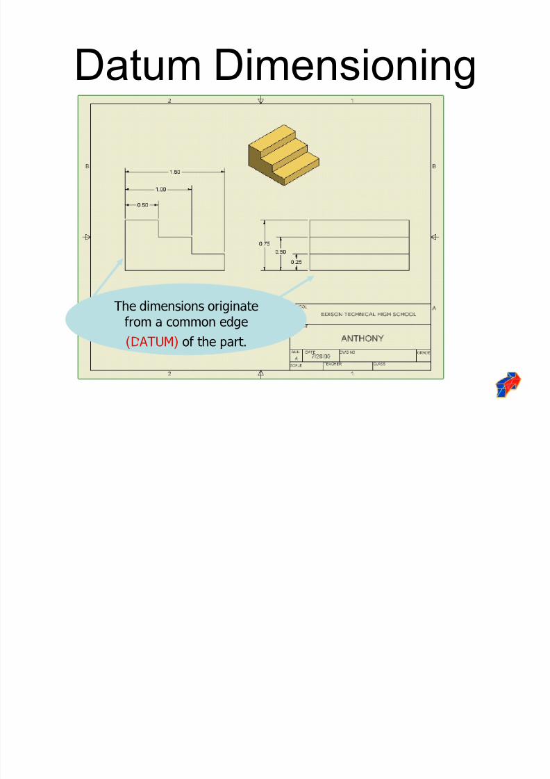
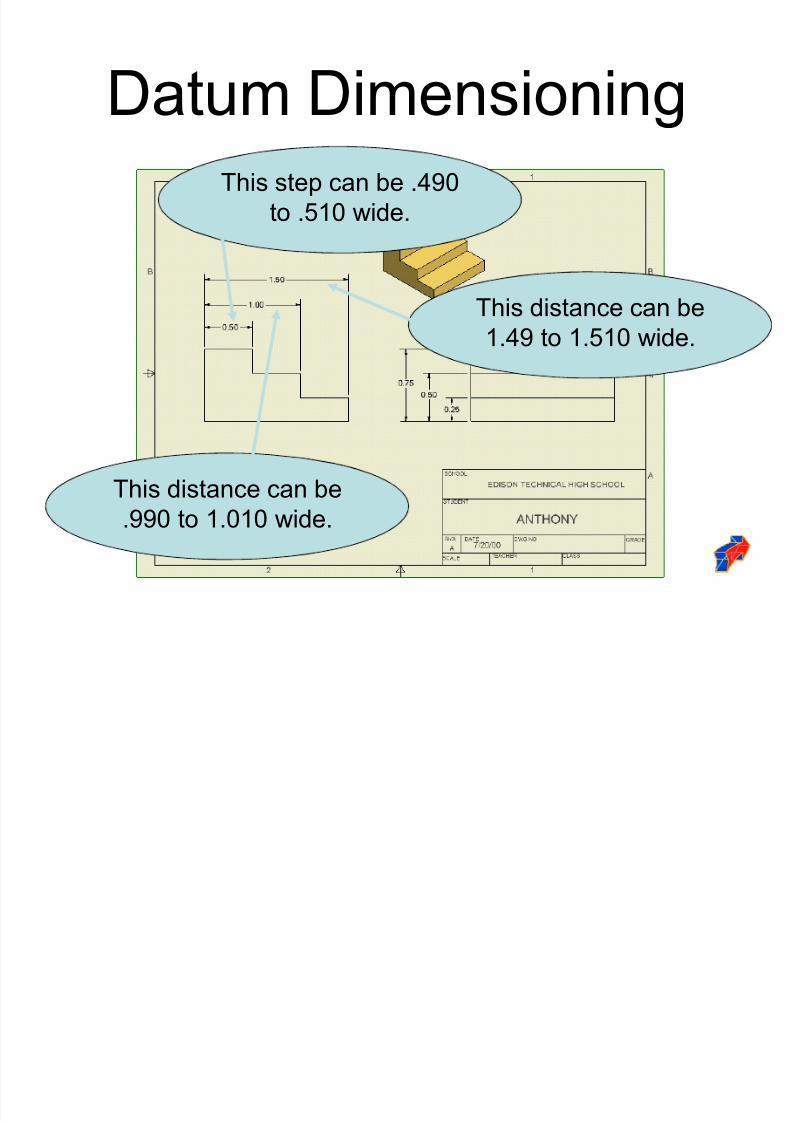
Datum Dimensioning
The dimensions originatefrom a common edge
(DATUM) of the part.
8/2/2019 Dimension Ing Standards
http://slidepdf.com/reader/full/dimension-ing-standards 25/48
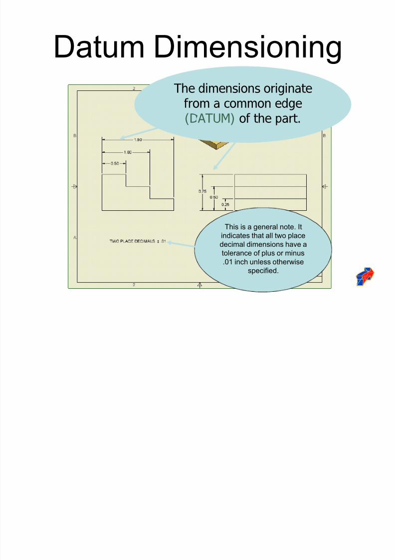
Datum DimensioningThe dimensions originate
from a common edge(DATUM) of the part.
This is a general note. It
indicates that all two place
decimal dimensions have a
tolerance of plus or minus
.01 inch unless otherwise
specified.
8/2/2019 Dimension Ing Standards
http://slidepdf.com/reader/full/dimension-ing-standards 26/48
Datum Dimensioning
This step can be .490
to .510 wide.
This distance can be
.990 to 1.010 wide.
This distance can be
1.49 to 1.510 wide.
8/2/2019 Dimension Ing Standards
http://slidepdf.com/reader/full/dimension-ing-standards 27/48
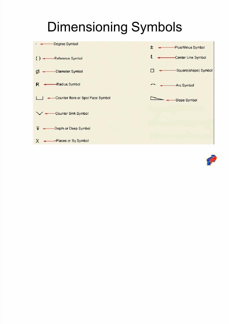
Dimensioning Symbols
8/2/2019 Dimension Ing Standards
http://slidepdf.com/reader/full/dimension-ing-standards 28/48
Dimensioning Angles
Angled surface may be dimensioned
using coordinate method to specify
the two location distances of theangle.
Angled surfaces may also be
dimensioned using the angular method by specifying one location
distance and the angle.
8/2/2019 Dimension Ing Standards
http://slidepdf.com/reader/full/dimension-ing-standards 29/48
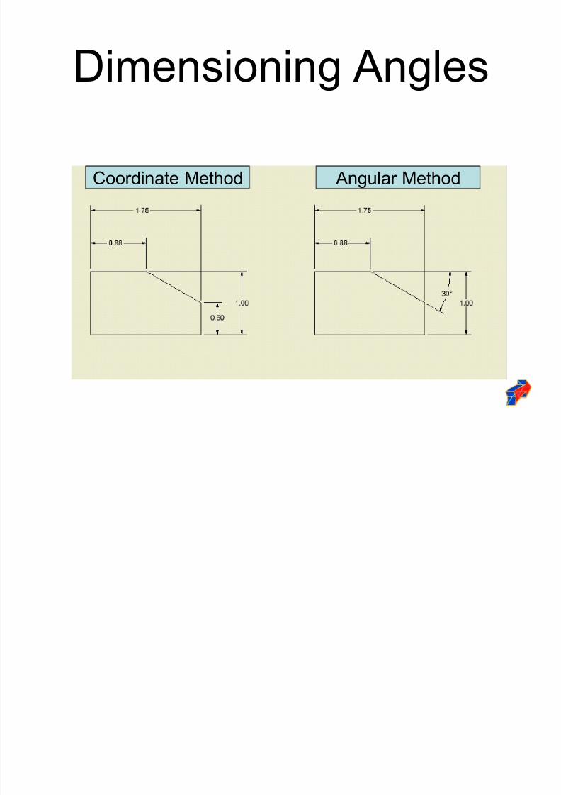
Dimensioning Angles
Coordinate Method Angular Method
8/2/2019 Dimension Ing Standards
http://slidepdf.com/reader/full/dimension-ing-standards 30/48
Dimensioning Arcs and
Circles Arcs and circles are dimensioned in views
that show the arc or circle.
Arcs are dimensioned with a leader toidentify the radius; in some cases, a center mark is included.
Circles should have a center mark and aredimensioned with a leader to identify thediameter.
8/2/2019 Dimension Ing Standards
http://slidepdf.com/reader/full/dimension-ing-standards 31/48
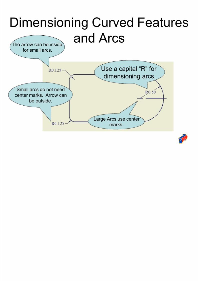
Dimensioning Curved Features
and Arcs
Use a capital ³R´ for dimensioning arcs.
Large Arcs use center
marks.
Small arcs do not need
center marks. Arrow can
be outside.
The arrow can be inside
for small arcs.
8/2/2019 Dimension Ing Standards
http://slidepdf.com/reader/full/dimension-ing-standards 32/48
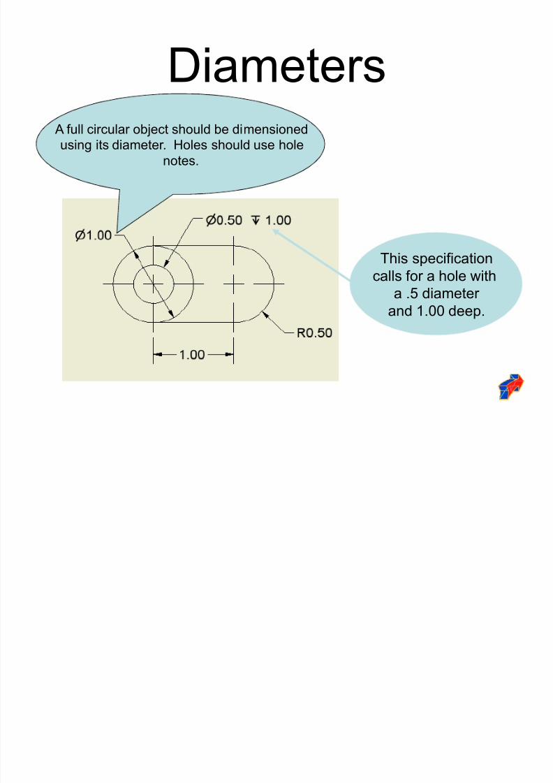
Diameters A full circular object should be dimensioned
using its diameter. Holes should use hole
notes.
This specification
calls for a hole with
a .5 diameter and 1.00 deep.
8/2/2019 Dimension Ing Standards
http://slidepdf.com/reader/full/dimension-ing-standards 33/48
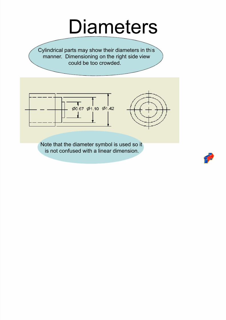
DiametersCylindrical parts may show their diameters in this
manner. Dimensioning on the right side view
could be too crowded.
Note that the diameter symbol is used so it
is not confused with a linear dimension.
8/2/2019 Dimension Ing Standards
http://slidepdf.com/reader/full/dimension-ing-standards 34/48
Chords
Chords may be dimensioned in one of
the following ways.
8/2/2019 Dimension Ing Standards
http://slidepdf.com/reader/full/dimension-ing-standards 35/48
Dimensioning Curved Features
Datum
Points are placed along the contour
and are dimensioned from the datum.
8/2/2019 Dimension Ing Standards
http://slidepdf.com/reader/full/dimension-ing-standards 36/48
Reference DimensionsDesignates more than one of the same feature.
In this case, it is identifying there are
two identical holes.
8/2/2019 Dimension Ing Standards
http://slidepdf.com/reader/full/dimension-ing-standards 37/48
ChamfersExternal chamfer for 45 degree
chamfers only.
There are two options.
External chamfer for angles other than
45 degrees.
Internal chamfers.
8/2/2019 Dimension Ing Standards
http://slidepdf.com/reader/full/dimension-ing-standards 38/48
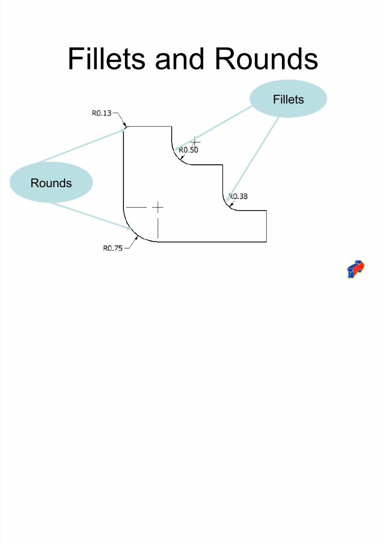
Fillets and Rounds
Rounds
Fillets
8/2/2019 Dimension Ing Standards
http://slidepdf.com/reader/full/dimension-ing-standards 39/48
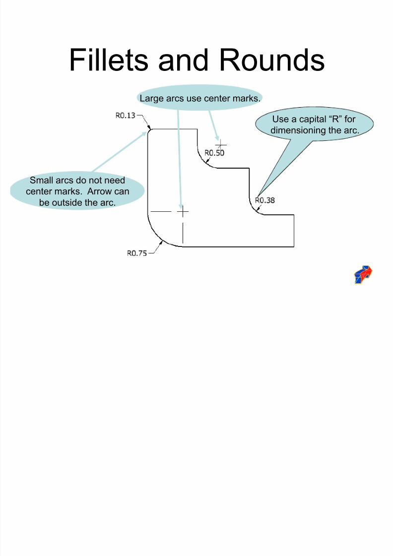
Fillets and RoundsUse a capital ³R´ for
dimensioning the arc.
Large arcs use center marks.
Small arcs do not need
center marks. Arrow can
be outside the arc.
8/2/2019 Dimension Ing Standards
http://slidepdf.com/reader/full/dimension-ing-standards 40/48
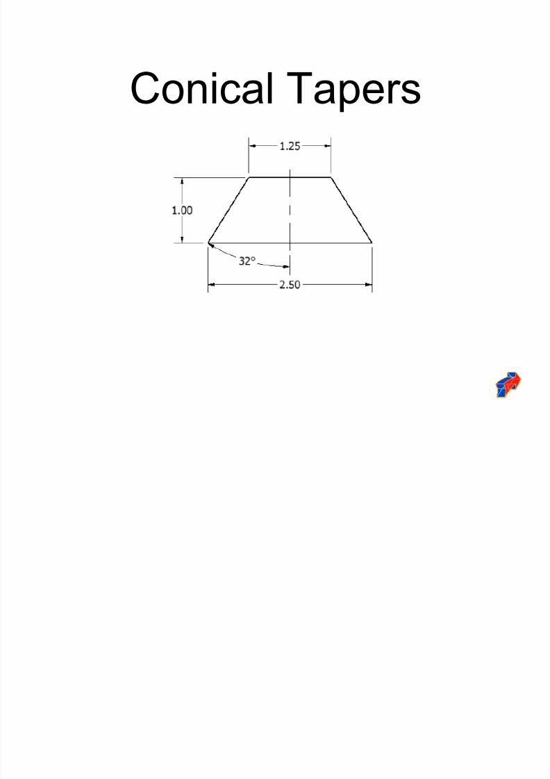
Conical Tapers
8/2/2019 Dimension Ing Standards
http://slidepdf.com/reader/full/dimension-ing-standards 41/48
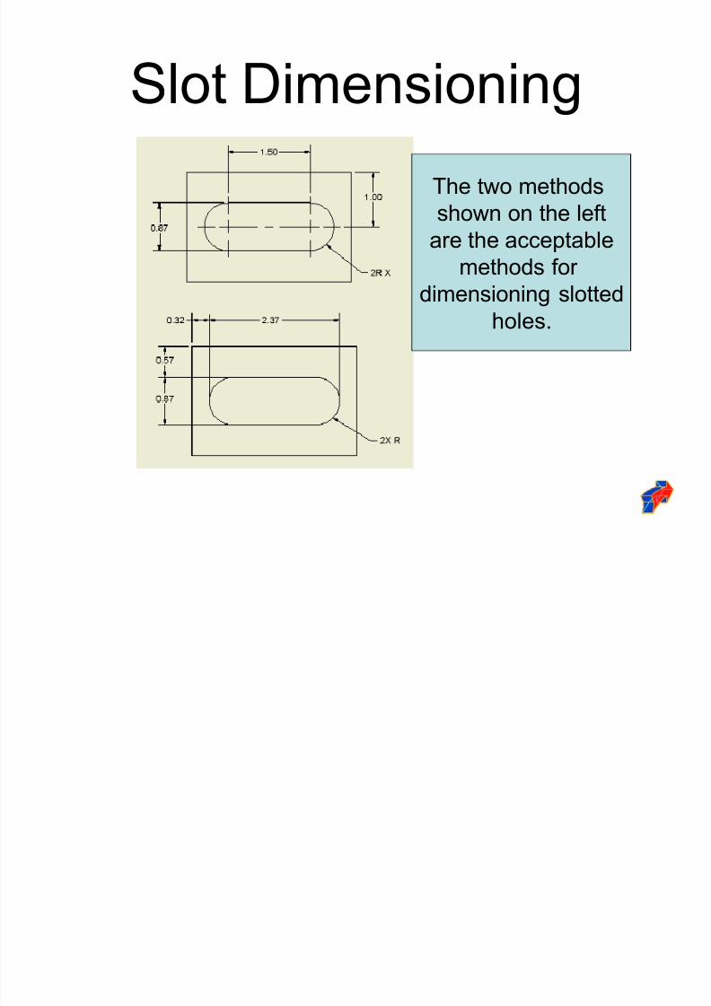
Slot Dimensioning
The two methods
shown on the left
are the acceptable
methods for
dimensioning slotted
holes.
8/2/2019 Dimension Ing Standards
http://slidepdf.com/reader/full/dimension-ing-standards 42/48
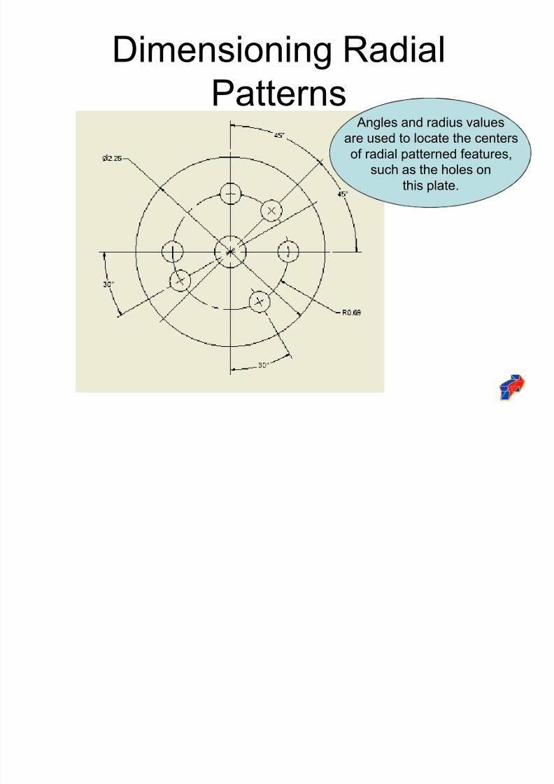
Dimensioning Radial
Patterns Angles and radius values
are used to locate the centers
of radial patterned features,
such as the holes on
this plate.
8/2/2019 Dimension Ing Standards
http://slidepdf.com/reader/full/dimension-ing-standards 43/48
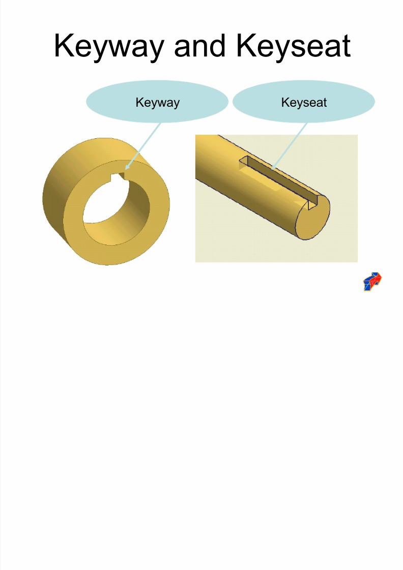
Keyway and Keyseat
Keyway Keyseat
8/2/2019 Dimension Ing Standards
http://slidepdf.com/reader/full/dimension-ing-standards 44/48
Shaft
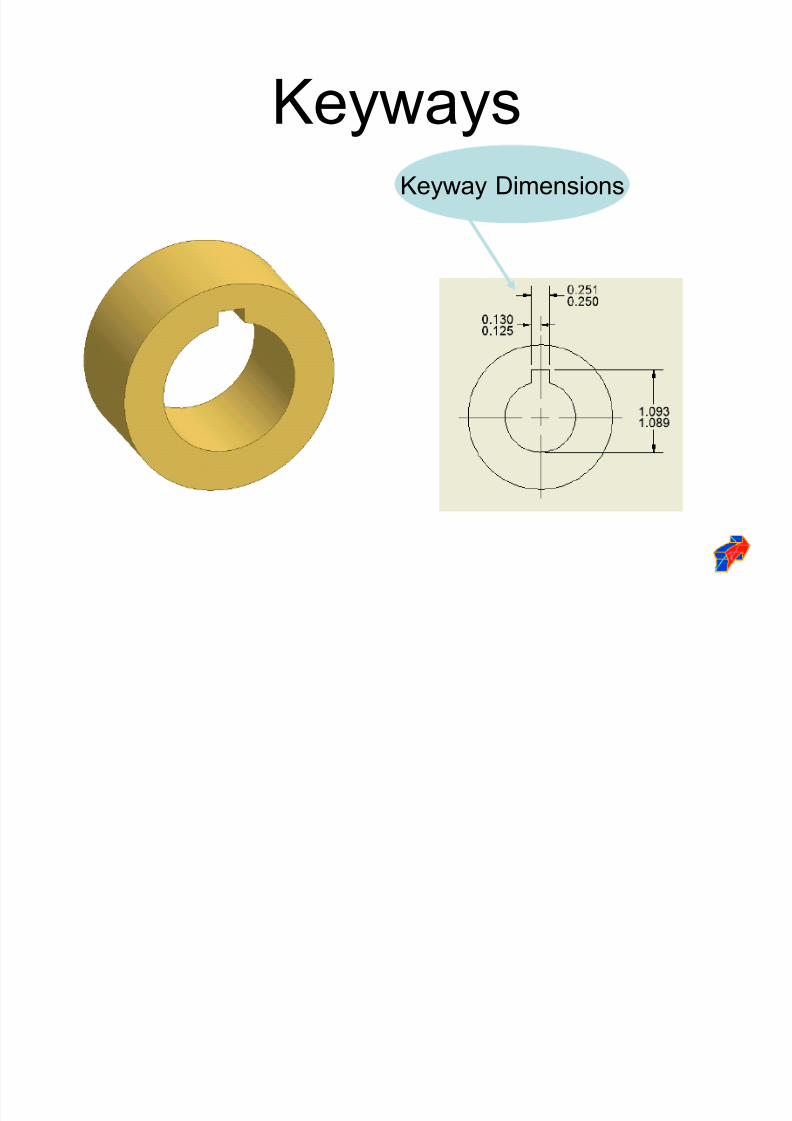
KeywaysKeyway Dimensions
8/2/2019 Dimension Ing Standards
http://slidepdf.com/reader/full/dimension-ing-standards 45/48
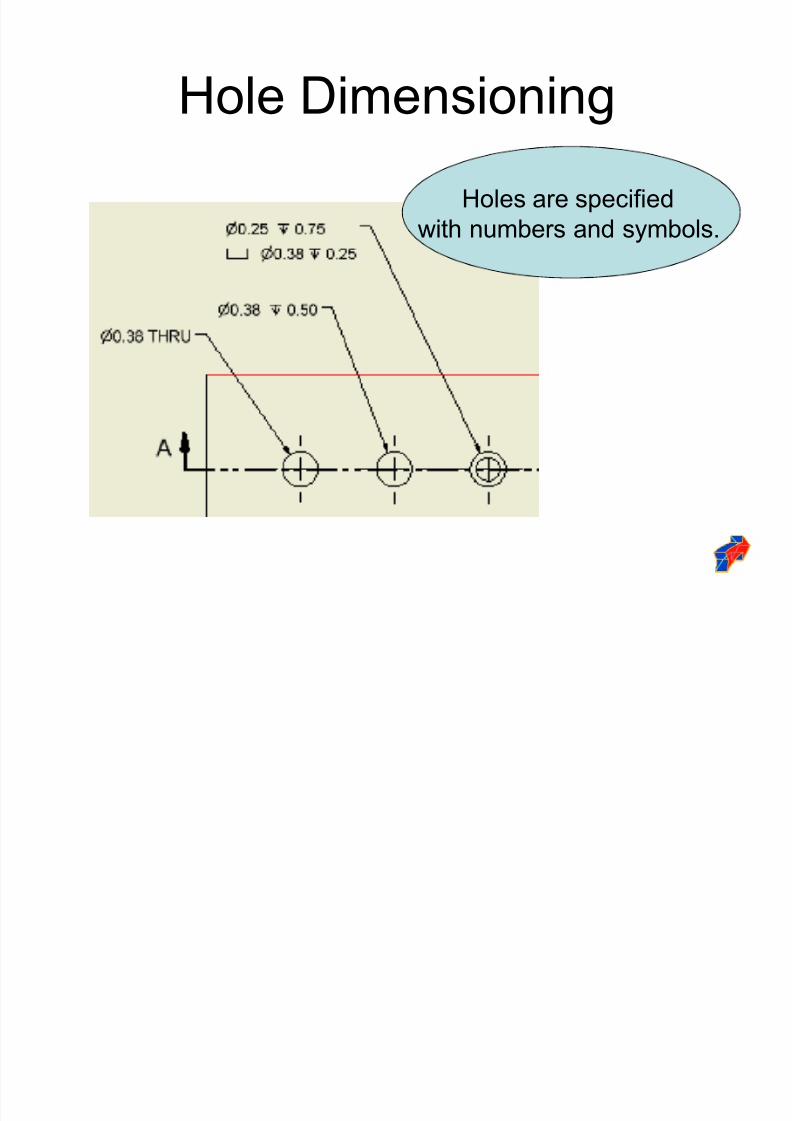
Hole Dimensioning
Holes are specified
with numbers and symbols.
8/2/2019 Dimension Ing Standards
http://slidepdf.com/reader/full/dimension-ing-standards 46/48
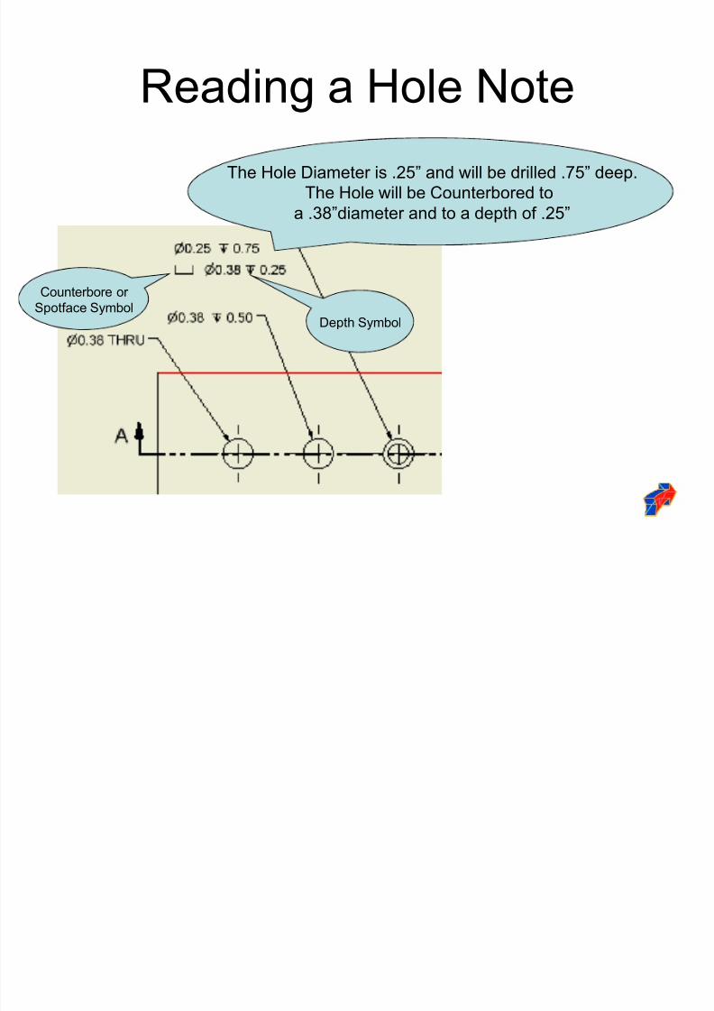
Reading a Hole Note
The Hole Diameter is .25´ and will be drilled .75´ deep.
The Hole will be Counterbored to
a .38´diameter and to a depth of .25´
Depth Symbol
Counterbore or
Spotface Symbol
8/2/2019 Dimension Ing Standards
http://slidepdf.com/reader/full/dimension-ing-standards 47/48
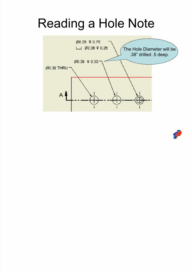
Reading a Hole Note
The Hole Diameter will be
.38´ drilled .5 deep.
8/2/2019 Dimension Ing Standards
http://slidepdf.com/reader/full/dimension-ing-standards 48/48
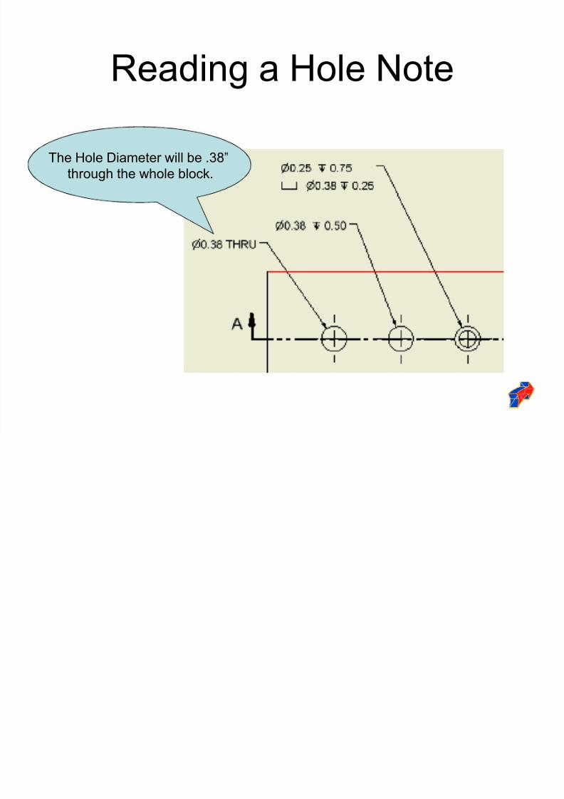
Reading a Hole Note
The Hole Diameter will be .38´
through the whole block.