Digital SD-HD AV Mixer - ID# 15350 - Converters.tv fileDigital SD-HD AV Mixer - ID# 15350 ......
19
Digital SD-HD AV Mixer - ID# 15350 Operation Manual
Transcript of Digital SD-HD AV Mixer - ID# 15350 - Converters.tv fileDigital SD-HD AV Mixer - ID# 15350 ......
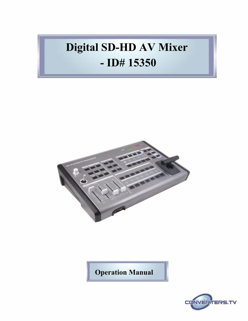
Digital SD-HD AV Mixer
- ID# 15350
Operation Manual
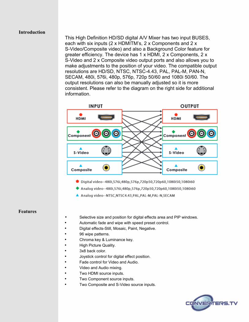
IntroductionThis High Definition HD/SD digital A/V Mixer has two input BUSES, each with six inputs (2 x HDMITM’s, 2 x Components and 2 x S-Video/Composite video) and also a Background Color feature for greater efficiency. The device has 1 x HDMI, 2 x Components, 2 x S-Video and 2 x Composite video output ports and also allows you to make adjustments to the position of your video. The compatible output resolutions are HD/SD, NTSC, NTSC-4.43, PAL, PAL-M, PAN-N, SECAM, 480i, 576i, 480p, 576p, 720p 50/60 and 1080i 50/60. The output resolutions can also be manually adjusted so it is more consistent. Please refer to the diagram on the right side for additional information.
Features• Selective size and position for digital effects area and PIP windows.
• Automatic fade and wipe with speed preset control.
• Digital effects-Still, Mosaic, Paint, Negative.
• 96 wipe patterns.
• Chroma key & Luminance key.
• High Picture Quality.
• 3x8 back color.
• Joystick control for digital effect position.
• Fade control for Video and Audio.
• Video and Audio mixing.
• Two HDMI source inputs.
• Two Component source inputs.
• Two Composite and S-Video source inputs.
• One HDMI recording output.
• Two Component recording outputs
• One Composite and S-Video recording outputs.
• One Composite and S-Video preview outputs (OSD).
• Auxiliary audio input.
• Microphone input and headphone output.
• Picture and Picture control. (3 window sizes)
• Each A/B BUS can adjust the Contrast/ Brightness/ Color/ HUE/ Detail & Aspect Ratio.
• Supports Lip-Sync delay up to 170ms.
• Composite supports 3D comb filter and YC separation.
• Motion and Edge Adaptive De-interlacing.Note:When receiving content that has HDCP encryption there will be no video output, the image will show with Blue screen.
Operation Controlsand Functions
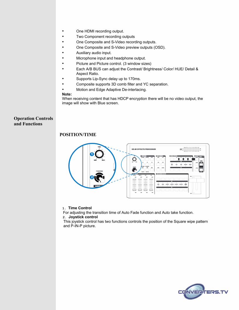
POSITION/TIME
1. Time ControlFor adjusting the transition time of Auto Fade function and Auto take function.2. Joystick controlThis joystick control has two functions controls the position of the Square wipe pattern and P-IN-P picture.
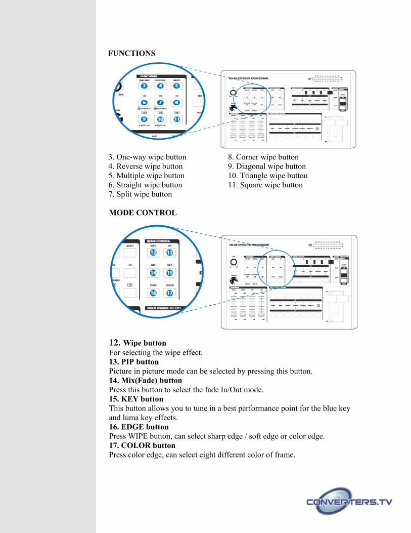
FUNCTIONS
3. One-way wipe button 8. Corner wipe button4. Reverse wipe button 9. Diagonal wipe button5. Multiple wipe button 10. Triangle wipe button6. Straight wipe button 11. Square wipe button7. Split wipe button
MODE CONTROL
12. Wipe buttonFor selecting the wipe effect.13. PIP buttonPicture in picture mode can be selected by pressing this button.14. Mix(Fade) buttonPress this button to select the fade In/Out mode.15. KEY buttonThis button allows you to tune in a best performance point for the blue keyand luma key effects.16. EDGE buttonPress WIPE button, can select sharp edge / soft edge or color edge.17. COLOR buttonPress color edge, can select eight different color of frame.
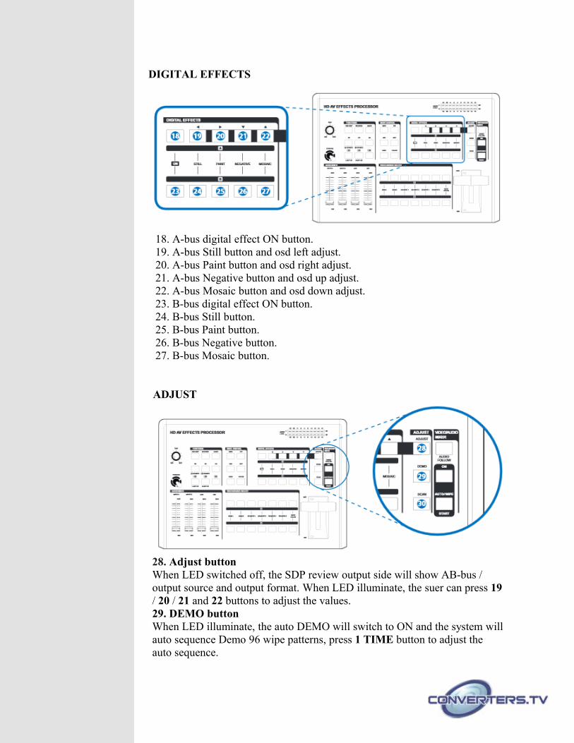
DIGITAL EFFECTS
18. A-bus digital effect ON button.19. A-bus Still button and osd left adjust.20. A-bus Paint button and osd right adjust.21. A-bus Negative button and osd up adjust.22. A-bus Mosaic button and osd down adjust.23. B-bus digital effect ON button.24. B-bus Still button.25. B-bus Paint button.26. B-bus Negative button.27. B-bus Mosaic button.
ADJUST
28. Adjust buttonWhen LED switched off, the SDP review output side will show AB-bus / output source and output format. When LED illuminate, the suer can press 19/ 20 / 21 and 22 buttons to adjust the values.29. DEMO buttonWhen LED illuminate, the auto DEMO will switch to ON and the system willauto sequence Demo 96 wipe patterns, press 1 TIME button to adjust the auto sequence.
30. SCAN buttonPress SCAN button for 3 seconds, the system will enter into SCAN function and will SCAN the input ports from 1 to 6 and record each port's format to the system.
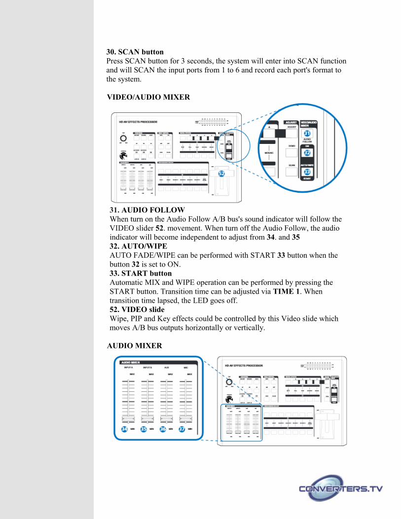
VIDEO/AUDIO MIXER
31. AUDIO FOLLOWWhen turn on the Audio Follow A/B bus's sound indicator will follow the VIDEO slider 52. movement. When turn off the Audio Follow, the audio indicator will become independent to adjust from 34. and 3532. AUTO/WIPEAUTO FADE/WIPE can be performed with START 33 button when the button 32 is set to ON.33. START buttonAutomatic MIX and WIPE operation can be performed by pressing the START button. Transition time can be adjusted via TIME 1. When transition time lapsed, the LED goes off.52. VIDEO slideWipe, PIP and Key effects could be controlled by this Video slide which moves A/B bus outputs horizontally or vertically.
AUDIO MIXER
34. INPUT A: Controls the audio level of the input A.35. INPUT B: Controls the audio level of the input B.36. AUX: Controls the audio level of the Auxiliary input.37. MIC: Controls the audio level of the Microphone input.
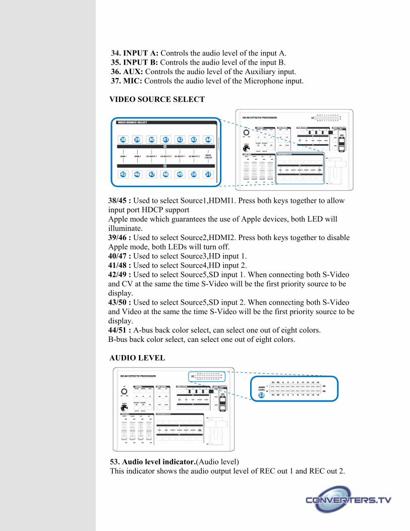
VIDEO SOURCE SELECT
38/45 : Used to select Source1,HDMI1. Press both keys together to allow input port HDCP support Apple mode which guarantees the use of Apple devices, both LED will illuminate.39/46 : Used to select Source2,HDMI2. Press both keys together to disable Apple mode, both LEDs will turn off.40/47 : Used to select Source3,HD input 1.41/48 : Used to select Source4,HD input 2.42/49 : Used to select Source5,SD input 1. When connecting both S-Video and CV at the same the time S-Video will be the first priority source to be display.43/50 : Used to select Source5,SD input 2. When connecting both S-Video and Video at the same the time S-Video will be the first priority source to be display.44/51 : A-bus back color select, can select one out of eight colors.B-bus back color select, can select one out of eight colors.
AUDIO LEVEL
53. Audio level indicator.(Audio level)This indicator shows the audio output level of REC out 1 and REC out 2.
Hardware Description
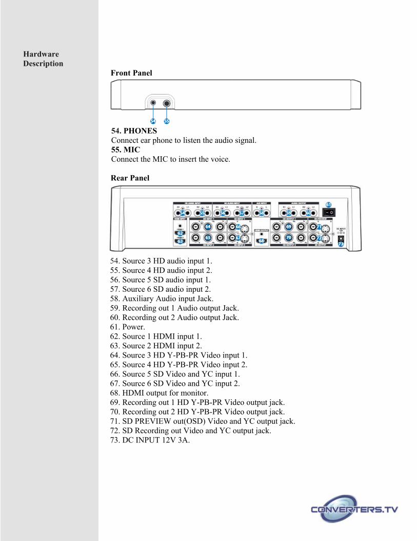
Front Panel
54. PHONESConnect ear phone to listen the audio signal.55. MICConnect the MIC to insert the voice.
Rear Panel
54. Source 3 HD audio input 1.55. Source 4 HD audio input 2.56. Source 5 SD audio input 1.57. Source 6 SD audio input 2.58. Auxiliary Audio input Jack.59. Recording out 1 Audio output Jack.60. Recording out 2 Audio output Jack.61. Power.62. Source 1 HDMI input 1.63. Source 2 HDMI input 2.64. Source 3 HD Y-PB-PR Video input 1.65. Source 4 HD Y-PB-PR Video input 2.66. Source 5 SD Video and YC input 1.67. Source 6 SD Video and YC input 2.68. HDMI output for monitor.69. Recording out 1 HD Y-PB-PR Video output jack.70. Recording out 2 HD Y-PB-PR Video output jack.71. SD PREVIEW out(OSD) Video and YC output jack.72. SD Recording out Video and YC output jack.73. DC INPUT 12V 3A.
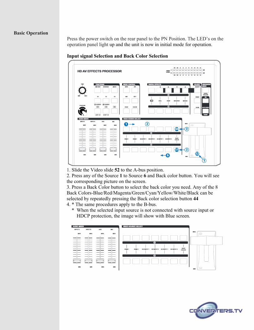
Basic OperationPress the power switch on the rear panel to the PN Position. The LED’s on theoperation panel light up and the unit is now in initial mode for operation.
Input signal Selection and Back Color Selection
1. Slide the Video slide 52 to the A-bus position.2. Press any of the Source 1 to Source 6 and Back color button. You will see the corresponding picture on the screen.3. Press a Back Color button to select the back color you need. Any of the 8 Back Colors-Blue/Red/Magenta/Green/Cyan/Yellow/White/Black can be selected by repeatedly pressing the Back color selection button 444. * The same procedures apply to the B-bus. * When the selected input source is not connected with source input or HDCP protection, the image will show with Blue screen.
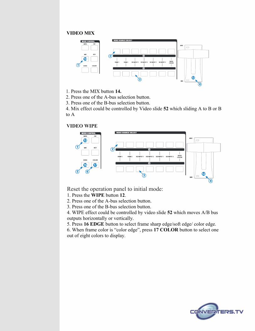
VIDEO MIX
1. Press the MIX button 14.2. Press one of the A-bus selection button. 3. Press one of the B-bus selection button. 4. Mix effect could be controlled by Video slide 52 which sliding A to B or B to A
VIDEO WIPE
Reset the operation panel to initial mode:1. Press the WIPE button 12.2. Press one of the A-bus selection button.3. Press one of the B-bus selection button.4. WIPE effect could be controlled by video slide 52 which moves A/B bus outputs horizontally or vertically.5. Press 16 EDGE button to select frame sharp edge/soft edge/ color edge.6. When frame color is “color edge”, press 17 COLOR button to select one out of eight colors to display.
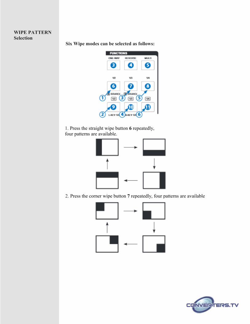
WIPE PATTERN Selection
Six Wipe modes can be selected as follows:
1. Press the straight wipe button 6 repeatedly, four patterns are available.
2. Press the corner wipe button 7 repeatedly, four patterns are available
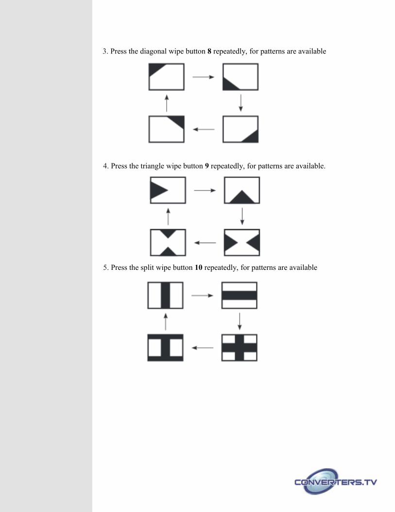
3. Press the diagonal wipe button 8 repeatedly, for patterns are available
4. Press the triangle wipe button 9 repeatedly, for patterns are available.
5. Press the split wipe button 10 repeatedly, for patterns are available
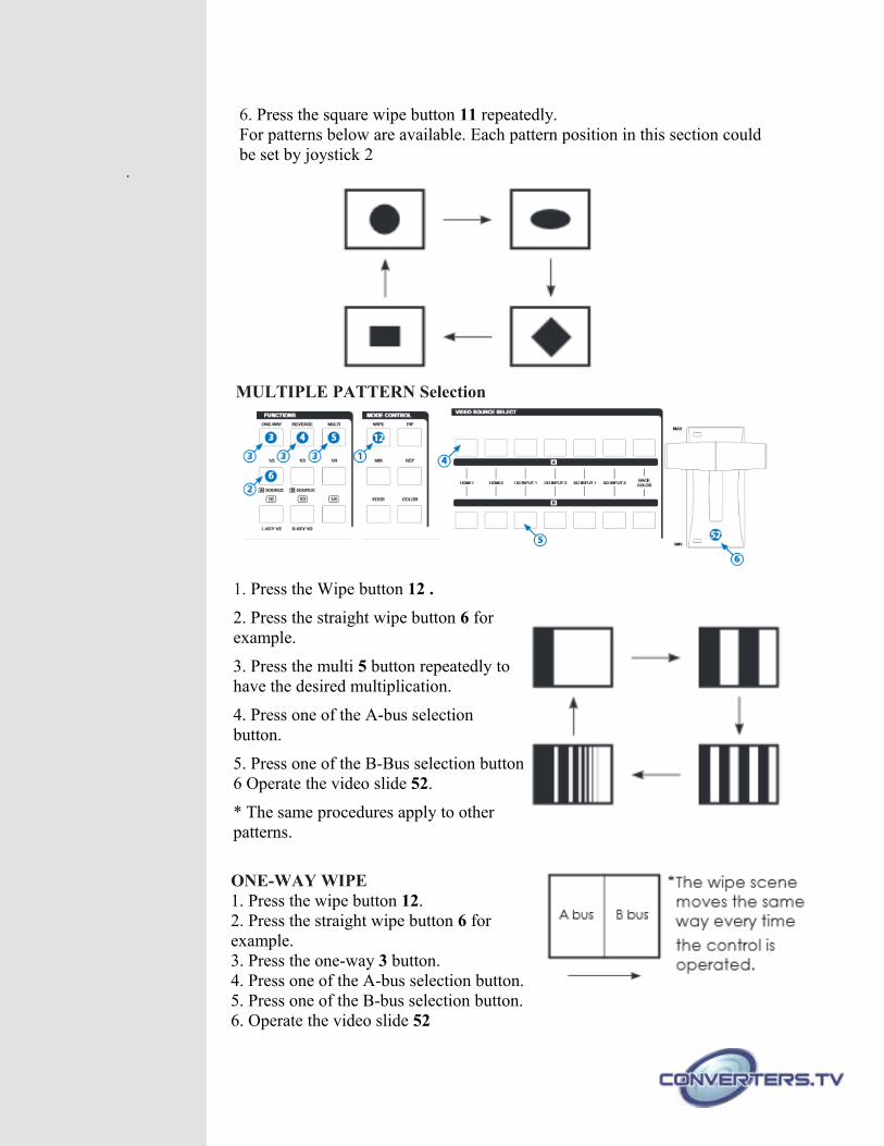
6. Press the square wipe button 11 repeatedly. For patterns below are available. Each pattern position in this section could be set by joystick 2
.
MULTIPLE PATTERN Selection
1. Press the Wipe button 12 .
2. Press the straight wipe button 6 forexample.
3. Press the multi 5 button repeatedly tohave the desired multiplication.
4. Press one of the A-bus selectionbutton.
5. Press one of the B-Bus selection button6 Operate the video slide 52.
* The same procedures apply to otherpatterns.
ONE-WAY WIPE1. Press the wipe button 12.2. Press the straight wipe button 6 forexample.3. Press the one-way 3 button.4. Press one of the A-bus selection button.5. Press one of the B-bus selection button.6. Operate the video slide 52
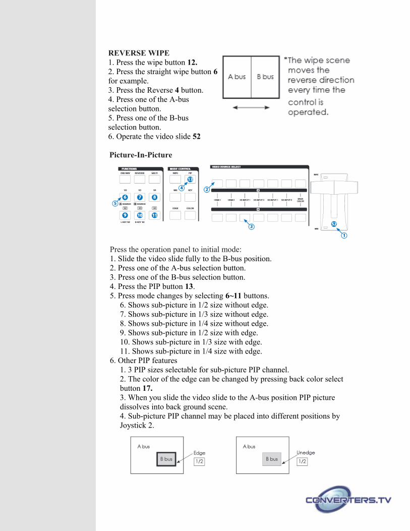
REVERSE WIPE1. Press the wipe button 12.2. Press the straight wipe button 6for example.3. Press the Reverse 4 button.4. Press one of the A-busselection button.5. Press one of the B-busselection button.6. Operate the video slide 52
Picture-In-Picture
Press the operation panel to initial mode:1. Slide the video slide fully to the B-bus position.2. Press one of the A-bus selection button.3. Press one of the B-bus selection button.4. Press the PIP button 13.5. Press mode changes by selecting 6~11 buttons.
6. Shows sub-picture in 1/2 size without edge.7. Shows sub-picture in 1/3 size without edge.8. Shows sub-picture in 1/4 size without edge.9. Shows sub-picture in 1/2 size with edge.10. Shows sub-picture in 1/3 size with edge.11. Shows sub-picture in 1/4 size with edge.
6. Other PIP features1. 3 PIP sizes selectable for sub-picture PIP channel.2. The color of the edge can be changed by pressing back color select button 17.3. When you slide the video slide to the A-bus position PIP picture dissolves into back ground scene.4. Sub-picture PIP channel may be placed into different positions by Joystick 2.
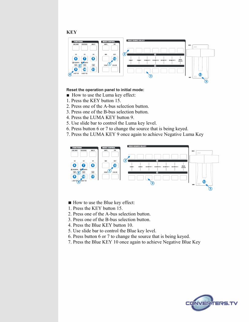
KEY
Reset the operation panel to initial mode:■ How to use the Luma key effect:1. Press the KEY button 15.2. Press one of the A-bus selection button.3. Press one of the B-bus selection button.4. Press the LUMA KEY button 9.5. Use slide bar to control the Luma key level.6. Press button 6 or 7 to change the source that is being keyed.7. Press the LUMA KEY 9 once again to achieve Negative Luma Key
■ How to use the Blue key effect:1. Press the KEY button 15.2. Press one of the A-bus selection button.3. Press one of the B-bus selection button.4. Press the Blue KEY button 10.5. Use slide bar to control the Blue key level.6. Press button 6 or 7 to change the source that is being keyed.7. Press the Blue KEY 10 once again to achieve Negative Blue Key
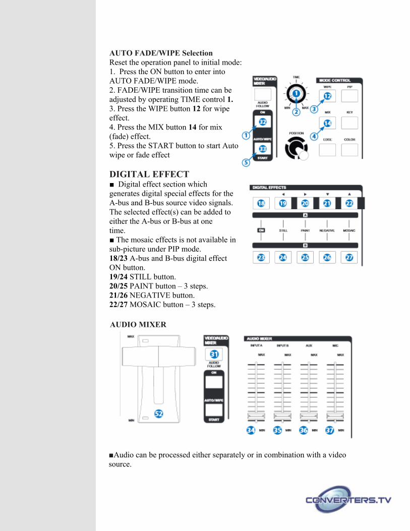
AUTO FADE/WIPE SelectionReset the operation panel to initial mode:1. Press the ON button to enter intoAUTO FADE/WIPE mode.2. FADE/WIPE transition time can beadjusted by operating TIME control 1.3. Press the WIPE button 12 for wipeeffect.4. Press the MIX button 14 for mix(fade) effect.5. Press the START button to start Autowipe or fade effect
DIGITAL EFFECT■ Digital effect section whichgenerates digital special effects for theA-bus and B-bus source video signals.The selected effect(s) can be added toeither the A-bus or B-bus at one time.■ The mosaic effects is not available insub-picture under PIP mode.18/23 A-bus and B-bus digital effectON button.19/24 STILL button.20/25 PAINT button – 3 steps.21/26 NEGATIVE button.22/27 MOSAIC button – 3 steps.
AUDIO MIXER
■Audio can be processed either separately or in combination with a video source.
31. When the AUDIO FOLLOW’s LED illuminate the Audio may be adjust by Video slider 52 along with the video. When the LED is off the Audio will be adjusted by 34, 35. 34. Adjust A-bus’s audio level.35. Adjust B-bus’s audio level.36. AUX: Controls the audio level of the auxiliary input.37. MIC: Controls the audio level of the microphone input
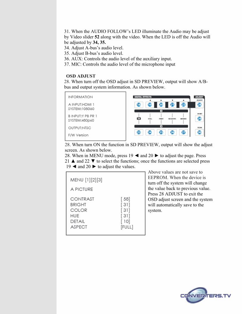
OSD ADJUST 28. When turn off the OSD adjust in SD PREVIEW, output will show A/B-bus and output system information. As shown below.
28. When turn ON the function in SD PREVIEW, output will show the adjustscreen. As shown below.28. When in MENU mode, press 19 ◄ and 20 ► to adjust the page. Press 21 ▲ and 22 ▼ to select the functions; once the functions are selected press 19 ◄ and 20 ► to adjust the values.
Above values are not save to EEPROM. When the device is turn off the system will change the value back to previous value. Press 28 ADJUST to exit the OSD adjust screen and the systemwill automatically save to the system.
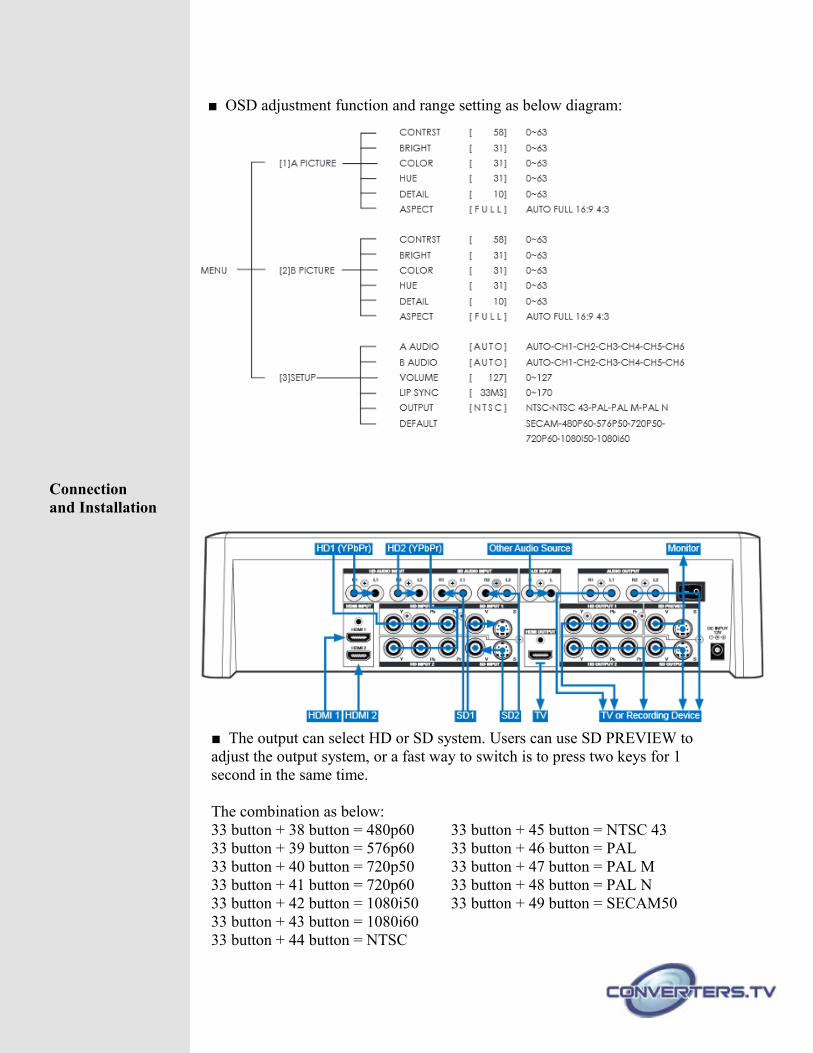
■ OSD adjustment function and range setting as below diagram:
Connectionand Installation
■ The output can select HD or SD system. Users can use SD PREVIEW to adjust the output system, or a fast way to switch is to press two keys for 1 second in the same time.
The combination as below:33 button + 38 button = 480p60 33 button + 45 button = NTSC 4333 button + 39 button = 576p60 33 button + 46 button = PAL33 button + 40 button = 720p50 33 button + 47 button = PAL M33 button + 41 button = 720p60 33 button + 48 button = PAL N33 button + 42 button = 1080i50 33 button + 49 button = SECAM5033 button + 43 button = 1080i6033 button + 44 button = NTSC
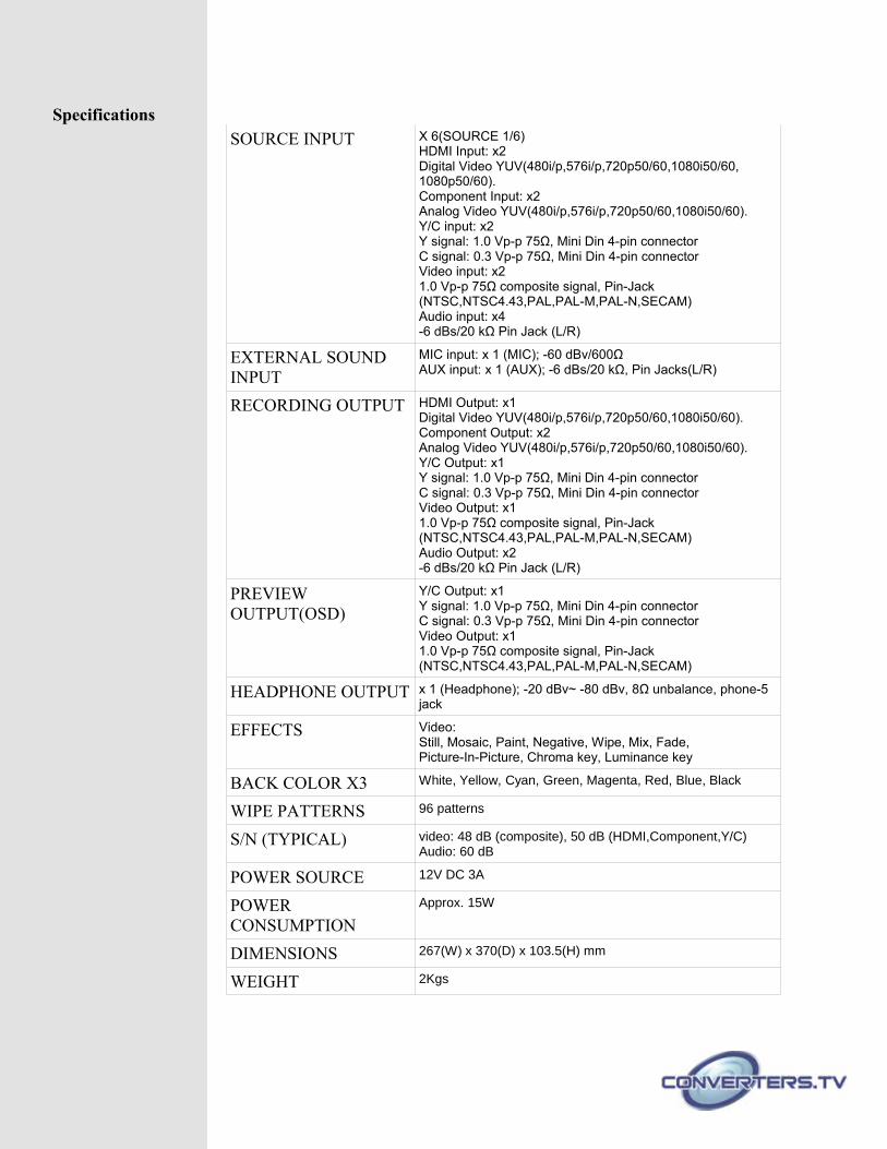
SpecificationsSOURCE INPUT X 6(SOURCE 1/6)
HDMI Input: x2Digital Video YUV(480i/p,576i/p,720p50/60,1080i50/60, 1080p50/60).Component Input: x2Analog Video YUV(480i/p,576i/p,720p50/60,1080i50/60).Y/C input: x2Y signal: 1.0 Vp-p 75Ω, Mini Din 4-pin connectorC signal: 0.3 Vp-p 75Ω, Mini Din 4-pin connectorVideo input: x21.0 Vp-p 75Ω composite signal, Pin-Jack(NTSC,NTSC4.43,PAL,PAL-M,PAL-N,SECAM)Audio input: x4-6 dBs/20 kΩ Pin Jack (L/R)
EXTERNAL SOUND INPUT
MIC input: x 1 (MIC); -60 dBv/600ΩAUX input: x 1 (AUX); -6 dBs/20 kΩ, Pin Jacks(L/R)
RECORDING OUTPUT HDMI Output: x1Digital Video YUV(480i/p,576i/p,720p50/60,1080i50/60).Component Output: x2Analog Video YUV(480i/p,576i/p,720p50/60,1080i50/60).Y/C Output: x1Y signal: 1.0 Vp-p 75Ω, Mini Din 4-pin connectorC signal: 0.3 Vp-p 75Ω, Mini Din 4-pin connectorVideo Output: x11.0 Vp-p 75Ω composite signal, Pin-Jack(NTSC,NTSC4.43,PAL,PAL-M,PAL-N,SECAM)Audio Output: x2-6 dBs/20 kΩ Pin Jack (L/R)
PREVIEW OUTPUT(OSD)
Y/C Output: x1Y signal: 1.0 Vp-p 75Ω, Mini Din 4-pin connectorC signal: 0.3 Vp-p 75Ω, Mini Din 4-pin connectorVideo Output: x11.0 Vp-p 75Ω composite signal, Pin-Jack(NTSC,NTSC4.43,PAL,PAL-M,PAL-N,SECAM)
HEADPHONE OUTPUT x 1 (Headphone); -20 dBv~ -80 dBv, 8Ω unbalance, phone-5 jack
EFFECTS Video:Still, Mosaic, Paint, Negative, Wipe, Mix, Fade,Picture-In-Picture, Chroma key, Luminance key
BACK COLOR X3 White, Yellow, Cyan, Green, Magenta, Red, Blue, Black
WIPE PATTERNS 96 patterns
S/N (TYPICAL) video: 48 dB (composite), 50 dB (HDMI,Component,Y/C) Audio: 60 dB
POWER SOURCE 12V DC 3A
POWER CONSUMPTION
Approx. 15W
DIMENSIONS 267(W) x 370(D) x 103.5(H) mm
WEIGHT 2Kgs