Digital Scanning | Guidelines
12
1 Cascade Dafo, Inc. 1360 Sunset Ave Ferndale, WA 98248 ph: 800.848.7332 fax: 855.543.0092 intl: +1 360 543 9306 www.cascadedafo.com Digital Scanning Guidelines 20210729 v.02 Digital Scanning | Guidelines Table of Contents Tips for Scanning Methods • Outside Fiberglass Cast • Plaster Positive Mold • Direct Patient Foot/Leg • Bio-foam Impression Scanning and Software • Suggested Scanning Setup ◦ Shopping List • Common Scanners ◦ Advantages ◦ Disadvantages • Common Software Accuracy Review Scan Evaluation Examples
Transcript of Digital Scanning | Guidelines

1Cascade Dafo, Inc. 1360 Sunset Ave
Ferndale, WA 98248ph: 800.848.7332fax: 855.543.0092
intl: +1 360 543 9306www.cascadedafo.com
Digital Scanning Guidelines 20210729 v.02
Digital Scanning | Guidelines
Table of Contents
Tips for Scanning Methods • Outside Fiberglass Cast • Plaster Positive Mold • Direct Patient Foot/Leg • Bio-foam Impression
Scanning and Software • Suggested Scanning Setup
◦ Shopping List • Common Scanners
◦ Advantages ◦ Disadvantages
• Common Software
Accuracy Review
Scan Evaluation Examples

2
OverviewFor more than a decade, Cascade Dafo has been utilizing a digital manufacturing process that results in an exceptionally accurate brace fit. This approach streamlines the ordering process, allowing practitioners to send digital scans rather than shipping casts to Cascade Dafo. We will continue to update our digital scanning guidelines and recommendations as scanning becomes a more common practice in the O&P industry and as the technology advances.
Benefits of Digital Scanning
Scanning Resources
Potential Physical Models
Scanning Equipment
Accepted File Format
How to send us your files
Support
Enter the order details directly into our e-Orders system and upload your digital scan files to:orders.cascadedafo.com
You can add photos or videos too!
If you have any questions contact:
Customer [email protected] | fax: 877.856.2160intl: +1 360 543 9306
Please convert your file to one of these file types before sending:
• The scanner you are using should have a tolerance level of +/-2mm, usually found in scanners using white light or laser technology.
• Follow the manufacturer’s recommendations for setup, use, care and maintenance including regular calibration.
• The best resource for information about scanning equipment is directly from the manufacturer for this rapidly evolving technology.
• Please note: The infrared iPad scanners currently on the market do not meet our criteria for an incoming scan tolerance of +/-2mm when used at the distance required for scanning AFOs.
For detailed techniques, take our free ABC-approved online course — Casting and Scanning for DAFOs — on the Cascade Dafo Institute.
For more info, including how-to videos, visit: cascadedafo.com/digital-scanning
File sizes between 1-25 MB.
Save the scan file in millimeters to ensure it imports to proper scale.
Click to see tips: Outside of fiberglass cast Plaster positive mold Patient foot/leg Bio-foam impression
Eliminates transportation time to Cascade Dafo
No cost for shipping casts to Cascade Dafo
Same excellent Cascade quality and Full (90-Day) Warranty
Available order status from your e-Order Dashboard
.stl .obj .ply*
*
* Recommended

3
Tips for ScanningSecure the fiberglass cast or plaster positive to a fixed location (if scanning a patient, ensure they can hold still). Position the physical model to capture all planes with the toes pointed up to expose the dorsum of the foot. We recommend scanning the outside of the cast to accurately capture the desired position of function while minimizing the prep work necessary to send an order to Cascade Dafo.
Tips for Scanning Each Model Type
Outside of fiberglass cast: • 2" or 3" white fiberglass wrap • Wrap 2-3 layers of wrap - less than 4mm thick • Close cut seam • Trim loose wrap • Use calipers to measure
cast thickness. See "How to measure cast thickness" video
• Click to see Suggested Scanning Setup
Direct scan of patient: • Patient needs to be able to sit still • Foot and ankle maintain intended position
of function without manipulation • Plexiglass surface recommended to simulate
weight bearing and capture intended brace angles
• Evaluate scan while patient is still present to rescan if needed
Plaster positive mold: • Secure physical model to strong anchor
point • Remove fiberglass remnants
Bio-foam impression: • For DAFO 7 only • Depth of impression must capture:
◦ Entire medial arch ◦ Heel cup ◦ Forefoot width ◦ Medial/lateral borders
• Directly scan Bio-foam impression
* Recommended

4
Scanning and SoftwareWe have tested a number of scanner and software combinations and found that the volume of the scan can vary from the physical model. In general, we have noticed that the higher end scanners have a greater accuracy. Factors to consider before selecting a scanner and software combination include number of patients, practitioners, technicians, workspace, etc.
Examples of Scanning Setups
Phone: • Recommend iPhone 11 or newer • Comb Scanning App • Using a rig to scan
Rig for scanning outside of fiberglass cast: • Calipers: to measure cast thickness
◦ iGaging 6” Digital Electronic Outside External OD Caliper • Gooseneck phone holder: allows adjustable angle for scanning casts.
◦ Cell Phone Clip on Stand Holder - with Grip Flexible Long Arm Gooseneck Bracket Mount Clamp • Turntable: allows ease of cast rotation to capture all planes.
◦ Lipper International Acacia Wood 18” Lazy Susan Kitchen Turntable • Clamp: to secure cast to gooseneck to avoid unwanted movement.
◦ Cheaplights - Heavy Duty Muslin Clamps 4 1/2 inch
Handheld: • White light scanner • Using a rig to scan
Advantages: • Freedom of
movement - no wires from device to computer
• Provides on-line live training
• Scans unaffected by: ◦ Lighting ◦ Cast Color ◦ Tape ◦ Staples
Advantages: • White light scanner
has years of use in the industry
• Supplied with CAS software included
Disadvantages: • No built in CAD
software • Requires use of web
portal to access scans
Disadvantages: • Limited mobility -
wired connection to computer
• High initial price point
• Typically additional cost per scan
• Can affect scan: ◦ Over-lighting ◦ Dark color cast ◦ Dark color tape
* Recommended
Gooseneck
Clamp
TurntableCast clamped on rig
Calipers
*

5
Common Scanners Used in O & P
Suggested Software
• Comb App ◦ Phone ◦ https://www.combscan.com/the-comb-app
• WillowWood Omega 3D ◦ Handheld ◦ https://www.willowwood.com/products-services/omega/hardware/omega-scanner-3d/
• Vorum Spectra 3D ◦ Handheld ◦ https://vorum.com/spectra-3d-scanner/
• Techmed 3D BodyScan ◦ Handheld ◦ https://techmed3d.com/products/bodyscan-scanner/
• Next Engine 3D Scanner Ultra HD ◦ Turntable ◦ http://www.nextengine.com/products
• Meshmixer ◦ Open source allows you to crop, fuse, and evaluate scan of your physical model ◦ https://www.meshmixer.com/
• Blender ◦ Open source with steep learning curve ◦ https://www.blender.org/
• Canfit ◦ License required ◦ https://vorum.com/canfit-op-cad-software/#
*
Scanning and Software continued
* Recommended

6* Recommended
Accuracy ReviewA difference in measurements between scan and physical model affects the volume and the intended fit of the DAFO. All scanners have the potential to create a scan that can pass a visual identification check, yet have a dimensional difference greater than +/- 2mm. The only way to identify this issue is to measure scan dimensions against the physical model. We recommend measuring at three points or at minimum the m/l metheads.
Tips to resolve: • Could be an isolated issue that can be resolved with a rescan. • Follow scanner manufacturer guidelines for troubleshooting and calibration process.
Physical Modelm/l met. heads
0.5mm difference
m/l malleoli
0.6mm difference
a/p calf
0.1mm difference
Scan*
67.3
52.6
71.5
66.8
53.2
71.6

7
Scan EvaluationWe have identified anomalies which can occur during the scanning process that may not affect our ability to fabricate a well-fitting DAFO. There are times when the anomaly is too great and requires a rescan of the physical model. The following are examples of what we are able to correct, not able to correct, and tips to resolve.
Holes: Pockets of missing data in the scan from the physical model.
Able to correct: • Minimal missing data • Limited guesswork of physical model • All anatomical features are fully represented
Tips to resolve: • Adjust angle of rig to allow scanner to fully capture all planes of physical model and then rescan • Utilize "Watertight", "Make Solid", "Solidify" or similar feature within scanning/CAD software
Unable to correct: • Large area(s) of missing data • Not able to recognize anatomical features

8
Scan Evaluation continuedUntrimmed: Scan has extra data not related to the physical model.
Able to correct: • When extra data can be trimmed without losing
or altering the intended physical model
The physical model and scanning rig are separable
Physical model and hand fused together
Physical model and table fused together
Unable to correct: • When an object and the physical model are
scanned together and inseparable without creating a large unusable hole
Tips to resolve: • Remove unneeded remnants of loose fiberglass from cast or plaster positive mold and rescan • Clear scanning area of everything except the scanning rig and physical model • Prior to finalizing, identify unneeded scan data and trim:
◦ Aspects of scanning rig (if scanning cast/plaster positive) ◦ Frame of plexiglass plate (if scanning patient directly) ◦ Loose Bio-foam (if scanning Bio-foam impression)

9
Scan Evaluation continuedScale Issue: The exported dimensions are saved as an increment other than millimeters (mm) which results in the scan being sized differently than the physical model.
Unfused: The independent shapes are not combined into a single digital object.
Able to correct: • A scan exported in identifiable units, inches (in) or
centimeters (cm)
Able to correct: • When the software is able to stitch separate data
points into a single digital object
Unable to correct: • A scan exported in units greater than inches, as
this creates guesswork for the amount needed to enlarge the scan and could result in low resolution scan issues
Unable to correct: • Algorithm fails to stitch separate data points
together
Measurements scaled in centimeters (left) or millimeters (right)
Tips to resolve: • Adjust scanning/CAD software settings to
mm
Tips to resolve: • Utilize "Watertight," "Make Solid," "Solidify,"
or similar feature within scanning/CAD software
10
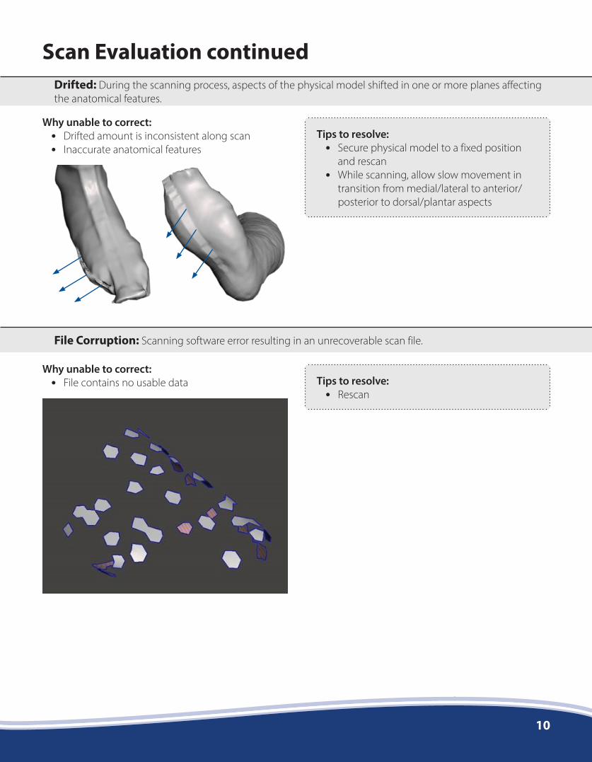
Scan Evaluation continuedDrifted: During the scanning process, aspects of the physical model shifted in one or more planes affecting the anatomical features.
File Corruption: Scanning software error resulting in an unrecoverable scan file.
Why unable to correct: • Drifted amount is inconsistent along scan • Inaccurate anatomical features
Why unable to correct: • File contains no usable data
Tips to resolve: • Secure physical model to a fixed position
and rescan • While scanning, allow slow movement in
transition from medial/lateral to anterior/posterior to dorsal/plantar aspects
Tips to resolve: • Rescan

11
Scan Evaluation continued
Low Resolution: Scan shape with large polygons distorting the details of the physical model.
Unclosed Seam: Physical model was scanned with the cut seam open.
Why unable to correct: • Not able to recognize anatomical features • Volume of scan does not match volume of
physical model
Why unable to correct: • Unknown volume added to open portion of scan
Tips to resolve: • Set resolution in scanning/CAD software to
a higher resolution • Adjust export settings to allow for 1 - 25 MB
file size
Tips to resolve: • Align cast wrap, close seam with staples or
tape, and then rescan

12
Scan Evaluation continued
Over-Smoothed: The loss of anatomical features during a smoothing process.
Why unable to correct: • Unable to estimate original features of physical
model • Entire volume of scan changed due to reducing
high points and increasing low points
Tips to resolve: • Turn off automated smoothing process
within the scanning/CAD software and rescan
• Do not apply smoothing tool/feature to scan
Smoothed
Flattens concave arches and bony prominences such as malleoli, heels, and metheads
Original