Digital Resistance Meter
139
IM 755601-01E 4th Edition Digital Resistance Meter
Transcript of Digital Resistance Meter

IM 755601-01E4th Edition
Digital Resistance Meter

Product RegistrationThank you for purchasing YOKOGAWA products.
YOKOGAWA provides registered users with a variety of information and services.Please allow us to serve you best by completing the product registration form accessible from our website.
http://tmi.yokogawa.com/
PIM 103-04E
iIM 755601-01E
4th Edition: October 2017 (YMI)All Rights Reserved, Copyright © 1999 Yokogawa Electric CorporationAll Rights Reserved, Copyright © 2013 Yokogawa Test & Measurement Corporation
Thank you for purchasing the YOKOGAWA Digital Resistance Meter 755601/755611.This User’s Manual contains useful information about the functions, operatingprocedures, and handling precautions of the instrument. To ensure correct use, pleaseread this manual thoroughly before operation.Keep this manual in a safe place for quick reference in the event a question arises.
Notes• The contents of this manual are subject to change without prior notice as a result of
continuing improvements to the instrument’s performance and functions. The figuresgiven in this manual may differ from the actual screen.
• Every effort has been made in the preparation of this manual to ensure the accuracyof its contents. However, should you have any questions or find any errors, pleasecontact your nearest YOKOGAWA dealer.
• Copying or reproducing all or any part of the contents of this manual withoutYOKOGAWA’s permission is strictly prohibited.
Trademarks• MS-DOS is a registered trademark of Microsoft Corporation.• PostScript is a registered trademark of Adobe Systems Incorporated.• Other company and product names are trademarks or registered trademarks of their
respective holders.
Revisions1st edition: July 19992nd edition: September 20133rd edition: May 20144th edition: October 2017

ii IM 755601-01E
Checking the Contents of the Package
Unpack the box and check the contents before operating the instrument. If some of thecontents are not correct or missing or if there is physical damage, contact the dealerfrom which you purchased them.
7556 Main UnitCheck that the model name and suffix code given on the name plate on the side panelmatch those on the order. When contacting the dealer from which you purchased theinstrument, please quote the instrument No.
Made in Japan
SUFFIX
MODEL
NO.Made in Japan
SUFFIX
MODEL
NO.
MODEL and SUFFIX codes
Model Name Suffix Code Specifications755601 0.01% resolution755611 0.001% resolutionPower supply -1 100 VAC
-4 120 VAC-6 220 VAC-8 240 VAC
Power cord1 -D UL/CSA Standards Power Cord (Part No.: A1006WD)[Maximum Rated Voltage: 125 V, Maximum Rated Current: 7 A]
-F VDE Standard Power Cord (Part No.: A1009WD)[Maximum Rated Voltage: 250 V, Maximum Rated Current: 10 A]
-Q BS Standard Power Cord (Part No.: A1054WD)[Maximum Rated Voltage: 250 V, Maximum Rated Current: 10 A]
-R SAA Standard Power Cord (Part No.: A1024WD)[Maximum Rated Voltage: 240 V, Maximum Rated Current: 10 A]
-H GB Standard Power Cord (complies with the CCC)(Part No.: A1064WD)[Maximum Rated Voltage: 250 V, Maximum Rated Current: 10 A]
Options /C1 GP-IB interface/C2 Centronics interface/C3 GP-IB & Centronics interface
1 Make sure that the attached power cord meets the designated standards of the country andarea that you are using it in.
NO. (Instrument No.)When contacting the dealer from which you purchased the instrument, please quote theinstrument No.

iiiIM 755601-01E
Standard AccessoriesThe following standard accessories are supplied with the instrument. Check that allitems are present and that they are undamaged.
Rubber feet(4 pieces)A9088ZM 2 sets
User's Manual (this manual) 1 pieceSpare power fusefor suffix code -1 & -4: A1345EF (1 piece)for suffix code -6 & -8: A1342EF (1 piece)
UL/CSA standardA1006WD
VDE standardA1009WD
BS standardA1054WD
SAA standardA1024WD
D F Q R
1. Power cord (one of the following power cordsis supplied according to the instrument's suffix codes)1
1 Make sure that the attached power cord meets the designated standards of the country and area that you are using it in.
H
GB StandardA1064WD
Note• We recommend you keep the packing box. The box is useful when you need to transport the
instrument.• For information regarding the fuse ratings, see section 11.5, “Replacing the Power Fuse.”
Checking the Contents of the Package
iv IM 755601-01E
Safety Precautions
This product is designed to be used by a person with specialized knowledge.This instrument is designed for indoor use only.The following general safety precautions must be observed during all phases ofoperation. If the instrument is used in a manner not specified in this manual, theprotection provided by the instrument may be impaired.This manual is an essential part of the product; keep it in a safe place for futurereference. YOKOGAWA assumes no liability for the customer’s failure to comply withthese requirements.
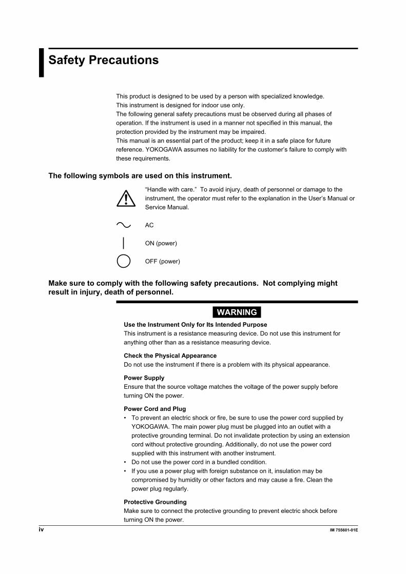
The following symbols are used on this instrument.
“Handle with care.” To avoid injury, death of personnel or damage to theinstrument, the operator must refer to the explanation in the User’s Manual orService Manual.
AC
ON (power)
OFF (power)
Make sure to comply with the following safety precautions. Not complying mightresult in injury, death of personnel.
WARNINGUse the Instrument Only for Its Intended PurposeThis instrument is a resistance measuring device. Do not use this instrument foranything other than as a resistance measuring device.
Check the Physical AppearanceDo not use the instrument if there is a problem with its physical appearance.
Power SupplyEnsure that the source voltage matches the voltage of the power supply beforeturning ON the power.
Power Cord and Plug• To prevent an electric shock or fire, be sure to use the power cord supplied by
YOKOGAWA. The main power plug must be plugged into an outlet with aprotective grounding terminal. Do not invalidate protection by using an extensioncord without protective grounding. Additionally, do not use the power cordsupplied with this instrument with another instrument.
• Do not use the power cord in a bundled condition.• If you use a power plug with foreign substance on it, insulation may be
compromised by humidity or other factors and may cause a fire. Clean thepower plug regularly.
Protective GroundingMake sure to connect the protective grounding to prevent electric shock beforeturning ON the power.
vIM 755601-01E
Safety Precautions
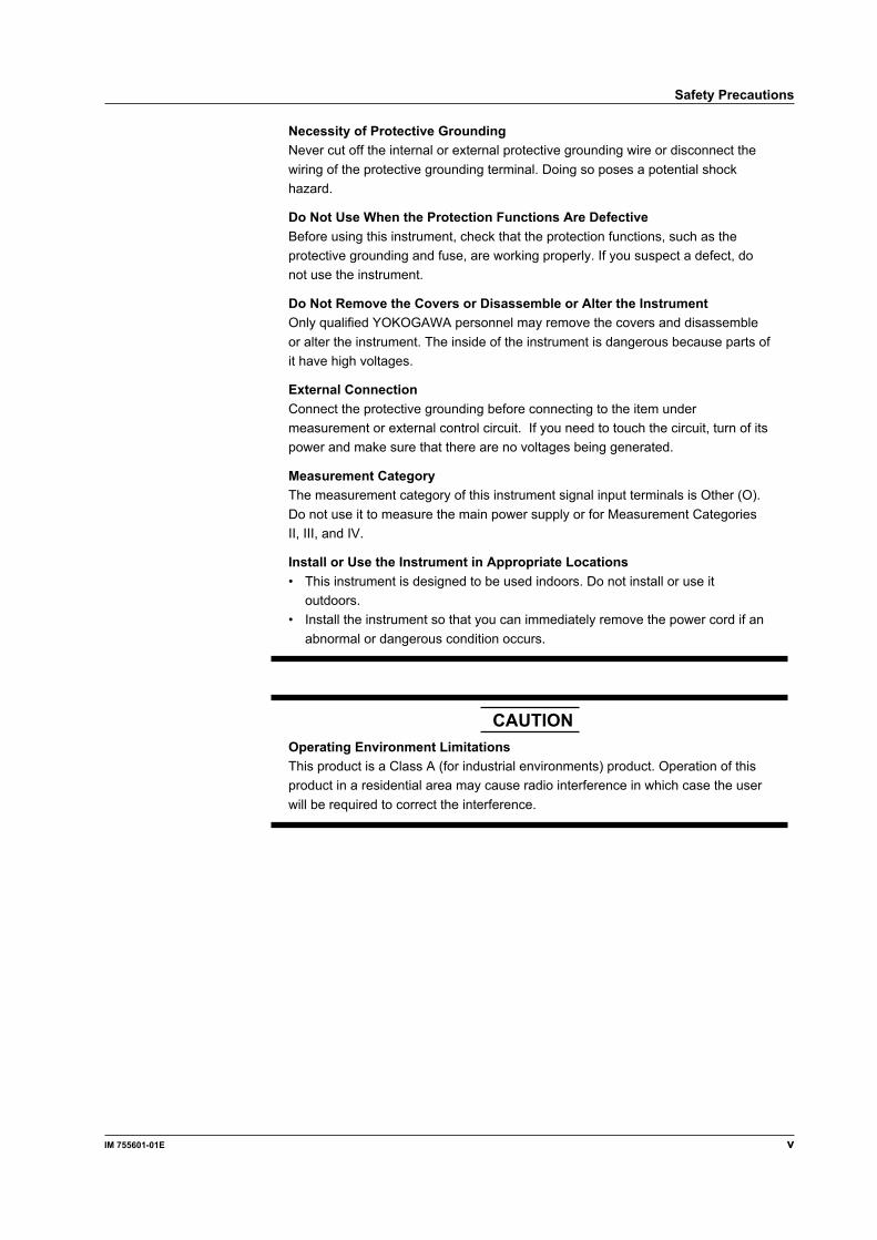
Necessity of Protective GroundingNever cut off the internal or external protective grounding wire or disconnect thewiring of the protective grounding terminal. Doing so poses a potential shockhazard.
Do Not Use When the Protection Functions Are DefectiveBefore using this instrument, check that the protection functions, such as theprotective grounding and fuse, are working properly. If you suspect a defect, donot use the instrument.
Do Not Remove the Covers or Disassemble or Alter the InstrumentOnly qualified YOKOGAWA personnel may remove the covers and disassembleor alter the instrument. The inside of the instrument is dangerous because parts ofit have high voltages.
External ConnectionConnect the protective grounding before connecting to the item undermeasurement or external control circuit. If you need to touch the circuit, turn of itspower and make sure that there are no voltages being generated.
Measurement CategoryThe measurement category of this instrument signal input terminals is Other (O).Do not use it to measure the main power supply or for Measurement CategoriesII, III, and IV.
Install or Use the Instrument in Appropriate Locations• This instrument is designed to be used indoors. Do not install or use it
outdoors.• Install the instrument so that you can immediately remove the power cord if an
abnormal or dangerous condition occurs.
CAUTIONOperating Environment LimitationsThis product is a Class A (for industrial environments) product. Operation of thisproduct in a residential area may cause radio interference in which case the userwill be required to correct the interference.
vi IM 755601-01E
Waste Electrical and Electronic Equipment
Waste Electrical and Electronic Equipment (WEEE), Directive(This directive is valid only in the EU.)This product complies with the WEEE directive marking requirement. This markingindicates that you must not discard this electrical/electronic product in domestichousehold waste.
Product CategoryWith reference to the equipment types in the WEEE directive, this product is classified asa “Monitoring and control instruments” product.
When disposing of products in the EU, contact your local Yokogawa Europe B.V. office.Do not dispose in domestic household waste.
EU Battery Directive
EU Battery Directive(This directive is valid only in the EU.)Batteries are included in this product. This marking indicates they shall be sorted out andcollected as ordained in the EU battery directive.
Battery type: Lithium battery
You cannot replace batteries by yourself. When you need to replace batteries, contactyour local Yokogawa Europe B.V. office.

viiIM 755601-01E
How to Use this Manual
Structure of the ManualThis User’s Manual consists of the following 12 chapters, and an index.
Chapter Title Description1 Functions Describes the measurement principles and
functions of the instrument. Operating proceduresare not given in this chapter. However, readingthis chapter will help you understand the operatingprocedures given in the chapters that follow.
2 Names and Uses of Parts Describes the names and uses of each part of theinstrument. For keys, references are given topages in the manual where operating proceduresare explained.
3 Before Starting Measurements Describes precautions on use, how to install theinstrument, how to connect the power supply, turnON/OFF the power switch, and other operations.
4 Setting the Measurement Conditions Describes how to set the measurement conditionssuch as measurement range and limits.
5 Making Measurements Describes how to make measurements.
6 Other Functions Describes how to save and recall measured dataand how to print out the data.
7 Using the Handler Interface Describes the handler interface specifications, howto setup the handler interface, and the timing chart.
8 Using the Serial (RS-232) Interface Describes how to control this instrument from acontroller (such as a PC) and how to retrievemeasured data from the instrument via the serial(RS-232) interface.
9 Using the GP-IB Interface Describes how to control this instrument from acontroller (such as a PC) and how to retrievemeasured data from the instrument via the GP-IBinterface.
10 Using Communication Commands Describes communication commands and sampleprograms.
11 Error Messages and Maintenance, Describes the possible causes of problems andand Inspection their appropriate corrective measures. Describes
the messages that are displayed on the screen.Describes how to perform self-tests.
12 Specifications The specifications of the instrument are given ontables.
Index Gives an Index.
viii IM 755601-01E
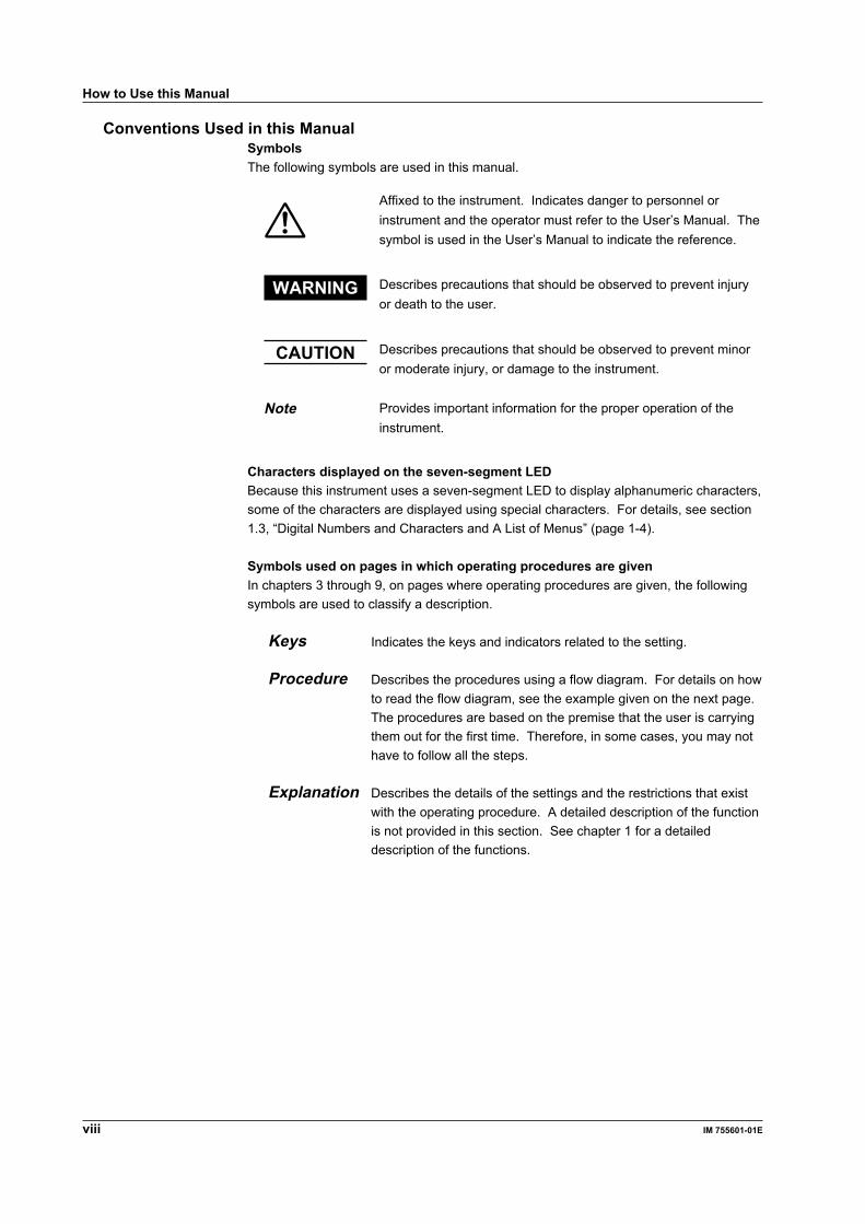
Conventions Used in this ManualSymbolsThe following symbols are used in this manual.
Affixed to the instrument. Indicates danger to personnel orinstrument and the operator must refer to the User’s Manual. Thesymbol is used in the User’s Manual to indicate the reference.
WARNING Describes precautions that should be observed to prevent injuryor death to the user.
CAUTION Describes precautions that should be observed to prevent minoror moderate injury, or damage to the instrument.
Note Provides important information for the proper operation of theinstrument.
Characters displayed on the seven-segment LEDBecause this instrument uses a seven-segment LED to display alphanumeric characters,some of the characters are displayed using special characters. For details, see section1.3, “Digital Numbers and Characters and A List of Menus” (page 1-4).
Symbols used on pages in which operating procedures are givenIn chapters 3 through 9, on pages where operating procedures are given, the followingsymbols are used to classify a description.
Keys Indicates the keys and indicators related to the setting.
Procedure Describes the procedures using a flow diagram. For details on howto read the flow diagram, see the example given on the next page.The procedures are based on the premise that the user is carryingthem out for the first time. Therefore, in some cases, you may nothave to follow all the steps.
Explanation Describes the details of the settings and the restrictions that existwith the operating procedure. A detailed description of the functionis not provided in this section. See chapter 1 for a detaileddescription of the functions.
How to Use this Manual

ixIM 755601-01E
A Procedure Example1. Pressing the SHIFT key then the MΩ key displays the contact check selection
menu.2. Press the REF
< or LIMIT
> key until the desired item appears on the screen.
3. Press the ENTER key to confirm the selection.4. If you selected bEF or AFt, enter the contact check level using the numerical keys.
Then, press the ENTER key to confirm.
1.
2.
3. 4.
REF LIMIT
ENTER
Ω,%
ENTER
Ω,%ENTER
Ω,%CHECKSHIFT
M Ω
(Contact check level)
Symbols Used in the SyntaxThe following table indicates symbols that are used in the syntax mainly in Chapter 10.These symbols are referred to as BNF (Backus-Naur Form) symbols. For details, seepages 10-5 and 10-6.
Symbol Meaning Example User Input Example<> Defined value :PANel:RECall<NRf><NRf>=0 to 9 →:PANEL:RECALL 3 Select a value from :MTIMeNORMal|FAST|HSPeed →:MTIME FAST| Exclusive OR[] Can be omitted :CHECK[:MODE]BEFore →:CHECK:BEFORE
How to Use this Manual

x IM 755601-01E
Contents
Checking the Contents of the Package ......................................................................................... iiSafety Precautions ....................................................................................................................... ivWaste Electrical and Electronic Equipment .................................................................................viEU Battery Directive .....................................................................................................................viHow to Use this Manual .............................................................................................................. vii
Chapter 1 Functions1.1 Block Diagram ........................................................................................................................... 1-11.2 Functions .................................................................................................................................. 1-21.3 Digital Numbers and Characters and A List of Menus .............................................................. 1-41.4 A List of Initial Values ................................................................................................................ 1-7
Chapter 2 Names and Uses of Parts2.1 Names of Parts ......................................................................................................................... 2-12.2 Keys and Error Displays ........................................................................................................... 2-2
Chapter 3 Before Starting Measurements3.1 Precautions on the Use of the instrument ................................................................................. 3-13.2 Installing the Instrument ............................................................................................................ 3-23.3 Connecting the Power Cord ...................................................................................................... 3-33.4 Wiring ........................................................................................................................................ 3-5
Chapter 4 Setting the Measurement Conditions4.1 Switching the Limit Mode .......................................................................................................... 4-14.2 Changing the Range (Reference) ............................................................................................. 4-24.3 Using the Comparator Function ................................................................................................ 4-44.4 Using the Contact Check Function ........................................................................................... 4-74.5 Setting the Measurement Time ................................................................................................. 4-84.6 Using the Trigger Function ........................................................................................................ 4-9
Chapter 5 Making Measurements5.1 Setting the Measurement Mode ................................................................................................ 5-15.2 Switching between Deviation (%) and Absolute (R) Displays ................................................... 5-3
Chapter 6 Other Functions6.1 Store/Recall Measured Data ..................................................................................................... 6-16.2 Printing Data ............................................................................................................................. 6-36.3 Initializing the Setup Information ............................................................................................... 6-7
Chapter 7 Using the Handler Interface7.1 Handler Interface Functions and Specifications ........................................................................ 7-17.2 Setting the Pulse Width of the EOM Signal .............................................................................. 7-47.3 Timing Chart .............................................................................................................................. 7-5
xiIM 755601-01E
Contents
Chapter 8 Using the Serial (RS-232) Interface8.1 Serial (RS-232) Interface Functions and Specifications ........................................................... 8-18.2 Connecting the Serial (RS-232) Interface Cable ....................................................................... 8-28.3 Handshaking ............................................................................................................................. 8-48.4 Data Format .............................................................................................................................. 8-68.5 Serial Communication Settings ................................................................................................. 8-7
Chapter 9 Using the GP-IB Interface9.1 GP-IB Interface Functions and Specifications .......................................................................... 9-19.2 Connecting the Interface Cable ................................................................................................ 9-39.3 Responses to Interface Messages ............................................................................................ 9-49.4 Switching to the Addressable Mode .......................................................................................... 9-69.5 Switching to the Talk-only Mode ................................................................................................ 9-8
Chapter 10 Communication Commands10.1 Before Programming ............................................................................................................... 10-1
10.1.1 Messages ...................................................................................................................................... 10-1
10.1.2 Commands .................................................................................................................................... 10-3
10.1.3 Responses .................................................................................................................................... 10-4
10.1.4 Data .............................................................................................................................................. 10-5
10.1.5 Synchronization with the Controller .............................................................................................. 10-7
10.1.6 Programming of Various Functions ............................................................................................... 10-9
10.2 Commands ............................................................................................................................ 10-1310.2.1 A List of Commands .................................................................................................................... 10-13
10.2.2 CHECk(contact CHECk) Group .................................................................................................. 10-15
10.2.3 COMMunicate Group .................................................................................................................. 10-16
10.2.5 HANDler Group ........................................................................................................................... 10-18
10.2.4 DISPlay Group ............................................................................................................................ 10-18
10.2.6 HEADer Group ............................................................................................................................ 10-19
10.2.7 LIMit Group ................................................................................................................................. 10-20
10.2.8 MEASure Group .......................................................................................................................... 10-22
10.2.9 MTIMe(Meas TIMe) Group .......................................................................................................... 10-23
10.2.10 PANel Group ............................................................................................................................... 10-23
10.2.11 PRINt Group (Option) ................................................................................................................. 10-24
10.2.12 READ Group ............................................................................................................................... 10-25
10.2.13 RECall Group .............................................................................................................................. 10-26
10.2.14 SELFtest Group .......................................................................................................................... 10-28
10.2.15 STATus Group ............................................................................................................................. 10-29
10.2.16 STORe Group ............................................................................................................................. 10-30
10.2.17 TRIGger Group ........................................................................................................................... 10-32
10.2.18 Common Command Group ......................................................................................................... 10-33
10.3 Status Report ........................................................................................................................ 10-3610.3.1 About the Status Report .............................................................................................................. 10-36
10.3.2 Status Byte .................................................................................................................................. 10-37
10.3.3 Standard event register ............................................................................................................... 10-38
10.3.4 Extended Event Register ............................................................................................................ 10-39
10.3.5 Output Queue and Error Queue .................................................................................................. 10-40
10.4 ASCII Character Codes ........................................................................................................ 10-4110.5 About the IEEE.488.2-1992 Standard ................................................................................... 10-42
1
2
3
4
5
6
7
8
9
10
11
12
Index

xii IM 755601-01E
Chapter 11 Error Messages, Maintenance, and Inspection11.1 Troubleshooting ...................................................................................................................... 11-111.2 Messages and Corrective Actions ........................................................................................... 11-211.3 Self Test .................................................................................................................................. 11-511.4 Adjustments ............................................................................................................................ 11-711.5 Replacing the Power Fuse .................................................................................................... 11-12
Chapter 12 Specifications12.1 Input Specifications ................................................................................................................. 12-112.2 Trigger Specifications .............................................................................................................. 12-312.3 Measurement Time Specifications .......................................................................................... 12-312.4 Contact Check Specifications ................................................................................................. 12-412.5 Comparator Specifications ...................................................................................................... 12-412.6 Other Specifications ................................................................................................................ 12-512.7 Handler Interface Specifications ............................................................................................. 12-512.8 Communication Specifications ................................................................................................ 12-612.9 General Specifications ............................................................................................................ 12-612.10 External Dimensions ............................................................................................................... 12-8
Index
Contents

Functions
1-1IM 755601-01E
11.1 Block Diagram
Block Diagram
HCUR
CPU
HPOT
LPOT
LCUR
+-
Constant current sourcefor measurement
A/Dconverter
D/Aconverter
Pre-amp
Comparator
Constant current sourcefor contact check
Diff. amp.
Analog section Digital section
A/Dinterface
Displayinterface
Printerinterface
Handlerinterface
Communicationinterface
Memory
Measurement PrincipleA constant current is fed through the resistor under measurement from the HCUR terminalto the LCUR terminal, and the voltage difference between the HPOT and LPOT terminals ismeasured. Because the electric potential at the HPOT terminal is controlled so that it isequal to the circuit’s common electric potential, the resistance can be determined bydividing the voltage at the LPOT terminal by the current.In the contact check that is performed before or after the measurement, a constantcurrent is fed from the HCUR terminal to the HPOT terminal and from the LPOT terminal tothe LCUR terminal. The voltage that appears across these terminals is compared with thereference voltage that was set by the D/A converter to check the connection to theresistor under measurement.Since the analog section is insulated from the digital section (electric potential of thecase), the circuit is robust against noise, resulting in a stable measurement. In addition,the handler interface is also insulated from the case in order to minimize noise influence.
Chapter 1 Functions
LOCAL keyGP-IB connector

1-2 IM 755601-01E
1.2 Functions
Comparator FunctionDetermines whether or not the measured result is within the comparison range setarbitrarily by the user. HI, IN, or LO mark is turned ON to indicate the comparator result.The result is also output via the handler interface.
Contact Check FunctionDetermines whether or not the item under measurement is properly connected to themeasurement input terminal, and the result is output via the handler interface. If an erroris detected, “ (no contact)” is displayed.
Trigger FunctionTrigger ModeThe instrument has the following three types of trigger modes:• External trigger: Makes a measurement when the instrument detects a rising or
falling edge of a signal that is applied to the external trigger inputterminal or the number 8 pin (EXT TRIG) of the handler interface.
• Manual trigger: Makes a measurement when the TRIG key on the front panel ispressed or whenever a trigger is activated via the communicationinterface.
• Internal trigger: Makes measurements at intervals which depend on the specifiedmeasurement time (auto sampling).
Trigger DelayThe measurement can then be started the specified time after the trigger occurrence. Atrigger delay is enabled when the trigger mode is set to external trigger or manual trigger.
Communication FunctionHandler and serial (RS-232) interfaces come standard with the instrument. A GP-IBinterface is also available as an option.
Printout FunctionBy using the optional Centronics interface, data stored in the memory, statistics collectedfrom those data, and other information can be printed to an external printer.
Functions
1-3IM 755601-01E
11.2 Functions
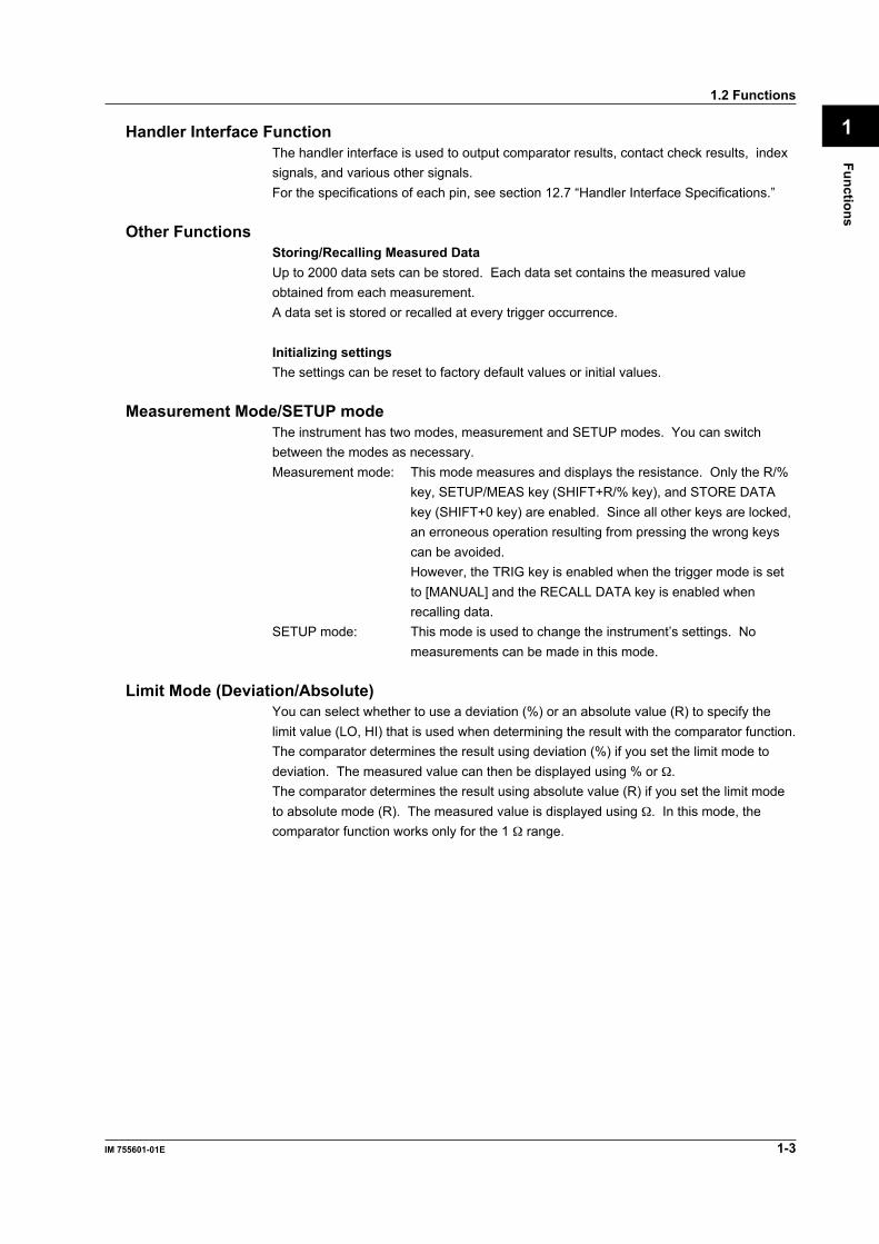
Handler Interface FunctionThe handler interface is used to output comparator results, contact check results, indexsignals, and various other signals.For the specifications of each pin, see section 12.7 “Handler Interface Specifications.”
Other FunctionsStoring/Recalling Measured DataUp to 2000 data sets can be stored. Each data set contains the measured valueobtained from each measurement.A data set is stored or recalled at every trigger occurrence.
Initializing settingsThe settings can be reset to factory default values or initial values.
Measurement Mode/SETUP modeThe instrument has two modes, measurement and SETUP modes. You can switchbetween the modes as necessary.Measurement mode: This mode measures and displays the resistance. Only the R/%
key, SETUP/MEAS key (SHIFT+R/% key), and STORE DATAkey (SHIFT+0 key) are enabled. Since all other keys are locked,an erroneous operation resulting from pressing the wrong keyscan be avoided.However, the TRIG key is enabled when the trigger mode is setto [MANUAL] and the RECALL DATA key is enabled whenrecalling data.
SETUP mode: This mode is used to change the instrument’s settings. Nomeasurements can be made in this mode.
Limit Mode (Deviation/Absolute)You can select whether to use a deviation (%) or an absolute value (R) to specify thelimit value (LO, HI) that is used when determining the result with the comparator function.The comparator determines the result using deviation (%) if you set the limit mode todeviation. The measured value can then be displayed using % or Ω.The comparator determines the result using absolute value (R) if you set the limit modeto absolute mode (R). The measured value is displayed using Ω. In this mode, thecomparator function works only for the 1 Ω range.
1-4 IM 755601-01E
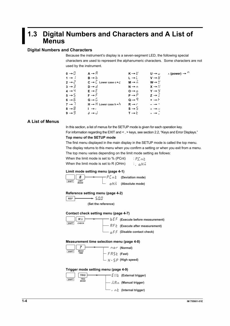
1.3 Digital Numbers and Characters and A List ofMenus
Digital Numbers and CharactersBecause the instrument’s display is a seven-segment LED, the following specialcharacters are used to represent the alphanumeric characters. Some characters are notused by the instrument.
0123456789
ABCDEFGHIJ
KLMNOPQRST
UVWXYZ+–×
÷
∧ (power)
Lower case c
Lower case h
A List of MenusIn this section, a list of menus for the SETUP mode is given for each operation key.For information regarding the EXIT and < , > keys, see section 2.2, “Keys and Error Displays.”Top menu of the SETUP modeThe first menu displayed in the main display in the SETUP mode is called the top menu.The display returns to this menu when you confirm a setting or when you exit from a menu.The top menu varies depending on the limit mode setting as follows:When the limit mode is set to % (PCnt) : When the limit mode is set to R (OHm) :
Limit mode setting menu (page 4-1)
LIMITMODE
SHIFT
8 (Deviation mode)
(Absolute mode)
Reference setting menu (page 4-2)REF
(Set the reference)
Contact check setting menu (page 4-7)
CHECKSHIFT
M Ω
(Disable contact check)
(Execute before measurement)
(Execute after measurement)
Measurement time selection menu (page 4-8)
MEASTIME
SHIFT
7 (Normal)
(Fast)
(High speed)
Trigger mode setting menu (page 4-9)
TRIGMODE
SHIFT
TRIG
(Internal trigger)
(External trigger)
(Manual trigger)

Functions
1-5IM 755601-01E
11.3 Digital Numbers and Characters and A List of Menus
Measured data store menu (page 6-1)
STOREDATA
SHIFT
0(Number of stored data sets)
Measured data recall menu (page 6-1)
RECALLDATA
SHIFT
.
Communication interface setting menu (page 8-7 and 9-6)
*
I/FSHIFT
3
* Displayed only on instruments that have the optional GP-IB interface.
1-6 IM 755601-01E
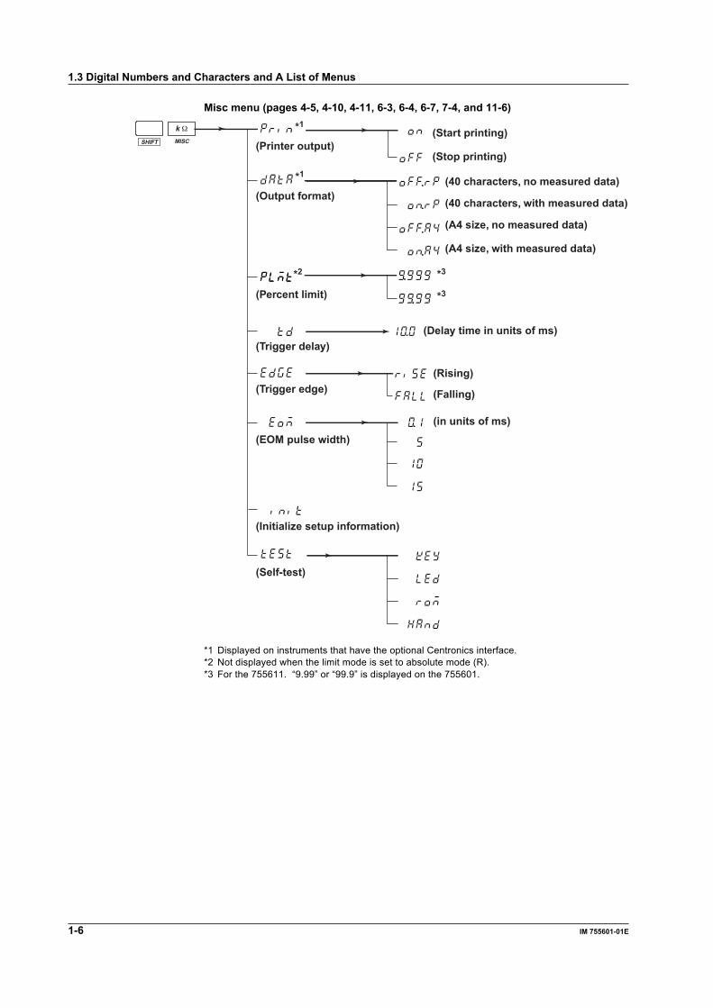
Misc menu (pages 4-5, 4-10, 4-11, 6-3, 6-4, 6-7, 7-4, and 11-6)
*1
*2
*1
MISCSHIFT
k Ω
*3
*3
(Printer output)(Start printing)
(Stop printing)
(Output format)(40 characters, no measured data)
(40 characters, with measured data)
(A4 size, no measured data)
(A4 size, with measured data)
(Percent limit)
(Trigger delay)(Delay time in units of ms)
(Trigger edge)(Rising)
(Falling)
(EOM pulse width)(in units of ms)
(Initialize setup information)
(Self-test)
*1 Displayed on instruments that have the optional Centronics interface.*2 Not displayed when the limit mode is set to absolute mode (R).*3 For the 755611. “9.99” or “99.9” is displayed on the 755601.
1.3 Digital Numbers and Characters and A List of Menus
Functions
1-7IM 755601-01E
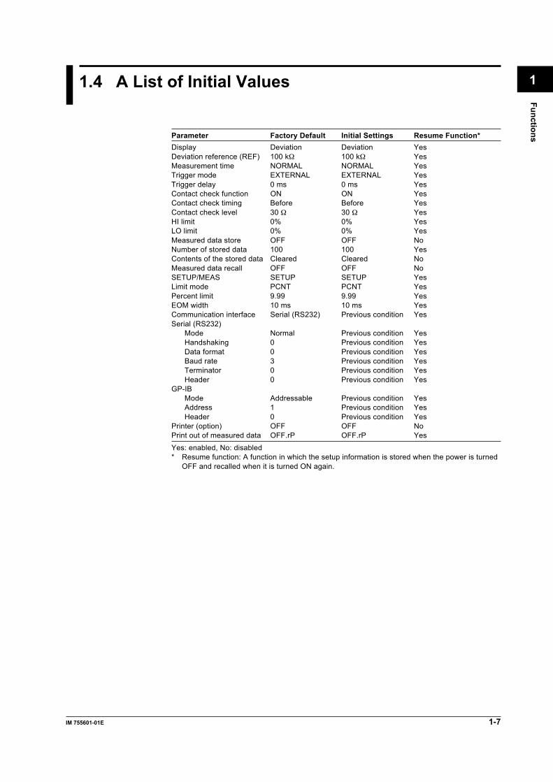
11.4 A List of Initial Values
Parameter Factory Default Initial Settings Resume Function*Display Deviation Deviation YesDeviation reference (REF) 100 kΩ 100 kΩ YesMeasurement time NORMAL NORMAL YesTrigger mode EXTERNAL EXTERNAL YesTrigger delay 0 ms 0 ms YesContact check function ON ON YesContact check timing Before Before YesContact check level 30 Ω 30 Ω YesHI limit 0% 0% YesLO limit 0% 0% YesMeasured data store OFF OFF NoNumber of stored data 100 100 YesContents of the stored data Cleared Cleared NoMeasured data recall OFF OFF NoSETUP/MEAS SETUP SETUP YesLimit mode PCNT PCNT YesPercent limit 9.99 9.99 YesEOM width 10 ms 10 ms YesCommunication interface Serial (RS232) Previous condition YesSerial (RS232)
Mode Normal Previous condition YesHandshaking 0 Previous condition YesData format 0 Previous condition YesBaud rate 3 Previous condition YesTerminator 0 Previous condition YesHeader 0 Previous condition Yes
GP-IBMode Addressable Previous condition YesAddress 1 Previous condition YesHeader 0 Previous condition Yes
Printer (option) OFF OFF NoPrint out of measured data OFF.rP OFF.rP Yes
Yes: enabled, No: disabled* Resume function: A function in which the setup information is stored when the power is turned
OFF and recalled when it is turned ON again.

Nam
es and Uses of Parts
2-1IM 755601-01E
2
Chapter 2 Names and Uses of Parts
LOCAL keyGP-IB connector
2.1 Names of Parts
Front Panel
DIGITAL RESISTANCE METER
NORMALMEAS&LOCK
SAMPLE
EXTERNAL
REFERENCE
UNKNOWN
MANUAL
L CUR L POT H POT H CUR
Do not connect a current/voltagesource to the UNKNOWN terminals.It will damage the instrument.
FAST
HI
HI LIMITEXIT
SETUP/MEAS
CHECK
MISCI/F
MEASTIME
STOREDATA
RECALLDATA
LOCAL ENTER
LIMITMODE
TRIGMODE
SHIFT
R/% REF LIMIT
TRIG7
1
0 .
2 3
54 6
8 9
LO LIMIT
IN
LOMΩ M Ω
k Ω
Ω,%
kΩ Ω
Ω
% %
HIGHSPEED
STOREDATA
RECALLDATA CHECK REMOTE
HI LIMIT display (4 digits on the 755601)
LO LIMIT display (4 digits on the 755601)Reference display
Numerical key/setting key (page 2-2)
Measurement input terminal (page 3-5)
Setting value/setting display (Main display, 5 digits on the 755601)
ALL TERMINALS 42 V PEAK TO
755601 Display ScreenNORMAL
MEAS&LOCK
SAMPLE
EXTERNAL
REFERENCE
MANUAL
FAST
HI
HI LIMIT
LO LIMIT
IN
LOMΩ
kΩ Ω
Ω
% %
HIGHSPEED
STOREDATA
RECALLDATA CHECK REMOTE
Rear Panel (for both 755601, 755611)
Power switch (page 3-4)
Handler interface connector (page 7-3)Serial (RS-232) interface connector (chapter 8)
External trigger inputterminal (page 4-11) Centronics interface connector (page 6-4)
GP-IB interface connector (chapter 9)
Fuse (page 11-12)Power connector (page 3-3)
HANDLER
ON
POWERFUSE
250V T 315mA
GP-IB(IEEE488)
100V AC25VA MAX
50/60Hz
OFF
SERIAL(RS-232)
TRIGGER IN
PRINTER

2-2 IM 755601-01E
2.2 Keys and Error Displays
Display
NORMALMEAS&LOCK
SAMPLE
EXTERNAL
REFERENCE
MANUAL
FAST
HI
HI LIMITEXIT
SETUP/MEAS
CHECK
MISCI/F
MEASTIME
STOREDATA
RECALLDATA
LOCAL ENTER
LIMITMODE
TRIGMODE
SHIFT
R/% REF LIMIT
TRIG7
1
0 .
2 3
54 6
8 9
LO LIMIT
IN
LOMΩ M Ω
k Ω
Ω,%
kΩ Ω
Ω
% %
HIGHSPEED
STOREDATA
RECALLDATA CHECK REMOTE
Lights every data sampleLights when the trigger mode is set to EXTERNAL
Lights when the trigger mode is set to MANUAL
Lights during contact check
Lights while recalling measured data
Lights while operating under remote control
Lights during measurement mode
The selected measurement time lights
Indicates the comparator result
Lights while storing measured data
Switching between measurement mode and SETUP modeSETUP/MEAS (SHIFT+R/%) keyThis key is used to switch between measurement mode and SETUP mode. Theinstrument is in the measurement mode when the “MEAS & LOCK” indicator is lit.
Keys used during the measurement modeR/% keyThis key is used to switch the unit between absolute (R) and deviation (%) in which themeasured value is displayed. When the limit mode is set to absolute (R), pressing thiskey will have no effect.
Nam
es and Uses of Parts
2-3IM 755601-01E
2
2.2 Keys and Error Displays
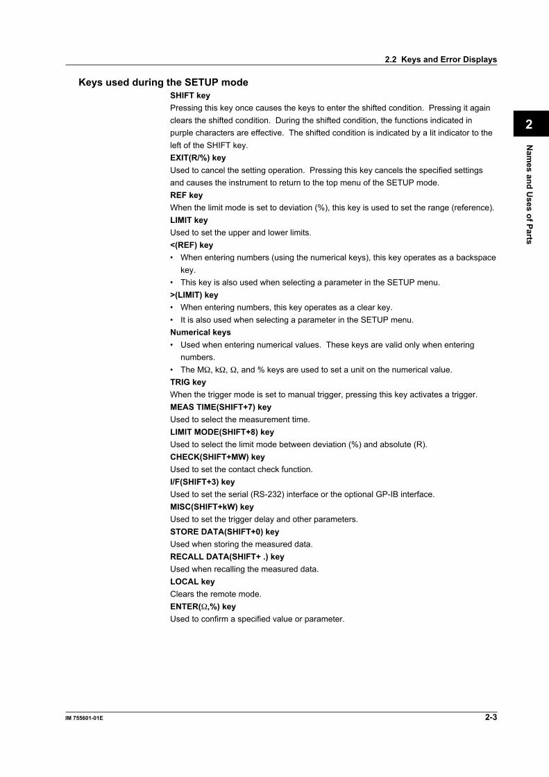
Keys used during the SETUP modeSHIFT keyPressing this key once causes the keys to enter the shifted condition. Pressing it againclears the shifted condition. During the shifted condition, the functions indicated inpurple characters are effective. The shifted condition is indicated by a lit indicator to theleft of the SHIFT key.EXIT(R/%) keyUsed to cancel the setting operation. Pressing this key cancels the specified settingsand causes the instrument to return to the top menu of the SETUP mode.REF keyWhen the limit mode is set to deviation (%), this key is used to set the range (reference).LIMIT keyUsed to set the upper and lower limits.<(REF) key• When entering numbers (using the numerical keys), this key operates as a backspace
key.• This key is also used when selecting a parameter in the SETUP menu.>(LIMIT) key• When entering numbers, this key operates as a clear key.• It is also used when selecting a parameter in the SETUP menu.Numerical keys• Used when entering numerical values. These keys are valid only when entering
numbers.• The MΩ, kΩ, Ω, and % keys are used to set a unit on the numerical value.TRIG keyWhen the trigger mode is set to manual trigger, pressing this key activates a trigger.MEAS TIME(SHIFT+7) keyUsed to select the measurement time.LIMIT MODE(SHIFT+8) keyUsed to select the limit mode between deviation (%) and absolute (R).CHECK(SHIFT+MW) keyUsed to set the contact check function.I/F(SHIFT+3) keyUsed to set the serial (RS-232) interface or the optional GP-IB interface.MISC(SHIFT+kW) keyUsed to set the trigger delay and other parameters.STORE DATA(SHIFT+0) keyUsed when storing the measured data.RECALL DATA(SHIFT+ .) keyUsed when recalling the measured data.LOCAL keyClears the remote mode.ENTER(Ω,%) keyUsed to confirm a specified value or parameter.

2-4 IM 755601-01E
Error DisplayOverrange displayWhen the measured value exceeds the display range or the maximum display value forthe corresponding measurement range, an overrange results. The display shows thefollowing when the measured value is over the range.“ ”
Display when an abnormality is detected in the test currentThe display when an abnormality is detected in the test current shows the following:“ ”
Contact check error displayWhen using the contact check function to make measurements, the display shows thefollowing when a contact check error occurs.“ ”
Other error displaysWhen an error that is described in section 11.2 “Messages and Corrective Actions”occurs, the corresponding error code is displayed as follows:“ ” or “ ”
Bar DisplayWhen the mode is switched from the SETUP mode to the measurement mode, thedisplay shows the following until the first measured value is displayed.“ ”
2.2 Keys and Error Displays
Before Starting M
easurements
3-1IM 755601-01E
3
Chapter 3 Before Starting Measurements
3.1 Precautions on the Use of the instrument
Safety PrecautionsIf you are using this instrument for the first time, make sure to thoroughly read the“Safety Precautions” given on page iii.
• Do not remove the cover from the instrument. Some sections inside the instrumenthave high voltages that are extremely dangerous. For internal inspection oradjustment, contact your nearest YOKOGAWA dealer as listed on the back cover ofthis manual.
• Never continue to use the instrument if there are any symptoms of trouble such asstrange smells or smoke coming from the instrument. In such cases, immediately turnOFF the power and unplug the power cord. Then, contact your nearest YOKOGAWAdealer as listed on the back cover of this manual.
• Nothing should be placed on top of the power cord. The power cord should also bekept away from any heat sources. When unplugging the power cord from the outlet,never pull the cord itself. Always hold the plug and pull it. If the power cord isdamaged, contact your dealer for replacement. Refer to page ii for the part numberwhen placing an order.
General Handling Precautions• Never place any objects containing water on top of the instrument. This may cause problems.• Do not apply shock to the input section. Applying shock to the input terminal or the
probe can cause electrical noise to enter the instrument.• When the instrument is not being used for an extended period of time, unplug the
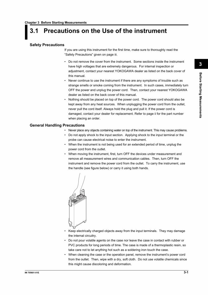
power cord from the outlet.• When moving the instrument, first, turn OFF the devices under measurement and
remove all measurement wires and communication cables. Then, turn OFF theinstrument and remove the power cord from the outlet. To carry the instrument, usethe handle (see figure below) or carry it using both hands.
• Keep electrically charged objects away from the input terminals. They may damagethe internal circuitry.
• Do not pour volatile agents on the case nor leave the case in contact with rubber orPVC products for long periods of time. The case is made of a thermoplastic resin, sotake care not to let anything hot such as a soldering iron touch the case.
• When cleaning the case or the operation panel, remove the instrument’s power cordfrom the outlet. Then, wipe with a dry, soft cloth. Do not use volatile chemicals sincethis might cause discoloring and deformation.
3-2 IM 755601-01E
3.2 Installing the Instrument
Installation conditionInstall the instrument in a place that meets the following conditions.Flat, even surfaceInstall the instrument on a stable horizontal surface. Otherwise, precise measurementsmay be impeded.Ambient temperature and humidityAmbient temperature: 5 to 40°CAmbient humidity: 20 to 80%RH (no condensation)Do not install the instrument in the following places:• Outdoor.• In direct sunlight or near heat sources.• Where an excessive amount of soot, steam, dust, or corrosive gases are present.• Where the instrument is exposed to water or other liquids.• Near strong magnetic field sources.• Near high voltage equipment or power lines.• Where the level of mechanical vibration is high.• In an unstable place.• In a place where the power switch cannot be accessed easily.
Note• For the most accurate measurements, use the instrument in the following environment.
Ambient temperature: 23±3°C, ambient humidity: 30 to 75%RH (no condensation)When using the instrument in a place where the ambient temperature is 5 to 18°C or 28 to40°C, add the temperature coefficient to the accuracy of the module as specified in chapter12, “Specifications.”
• When installing the instrument in a place where the ambient humidity is 30% or below, takemeasures to prevent static electricity such as using an anti-static mat.
• Internal condensation may occur if the instrument is moved to another place where both theambient temperature and humidity are higher, or if the temperature changes rapidly. In thiscase, let the instrument adjust to the new environment for at least one hour before using theinstrument. Check to see that there is no condensation.
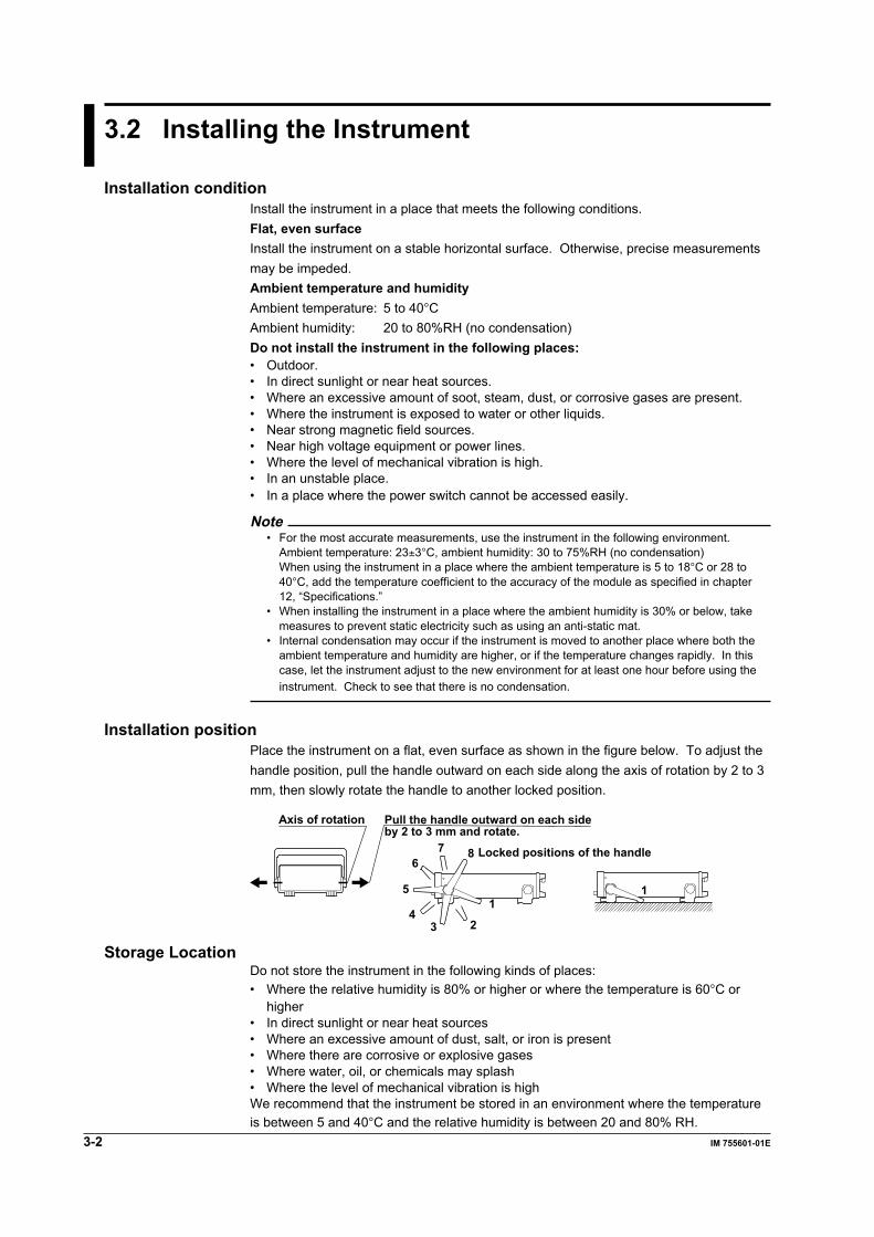
Installation positionPlace the instrument on a flat, even surface as shown in the figure below. To adjust thehandle position, pull the handle outward on each side along the axis of rotation by 2 to 3mm, then slowly rotate the handle to another locked position.
1
234
5
67 8
1
Axis of rotation Pull the handle outward on each sideby 2 to 3 mm and rotate.
Locked positions of the handle
Storage LocationDo not store the instrument in the following kinds of places:• Where the relative humidity is 80% or higher or where the temperature is 60°C or
higher• In direct sunlight or near heat sources• Where an excessive amount of dust, salt, or iron is present• Where there are corrosive or explosive gases• Where water, oil, or chemicals may splash• Where the level of mechanical vibration is highWe recommend that the instrument be stored in an environment where the temperatureis between 5 and 40°C and the relative humidity is between 20 and 80% RH.

Before Starting M
easurements
3-3IM 755601-01E
3
3.3 Connecting the Power Cord
Before connecting the powerFollow the warnings below to avoid electric shock and damage to the instrument.
WARNING• Connect the power cord only after confirming that the voltage of the
power supply matches the rated electric power voltage for theinstrument.
• Connect the power cord after checking that the power switch of theinstrument is turned OFF.
• To prevent electric shock or fire, always use the power cord supplied byYOKOGAWA.
• Always use protective grounding to prevent electric shock. Connect thepower cord of the instrument to a three-pole power outlet that has aprotective grounding terminal.
• Never use an extension cord that does not have protective grounding,otherwise the protection function will be compromised.
Connecting Procedure1. Check that the power switch on the rear panel is OFF.2. Connect the plug of the power cord that is included in the package to the power
connector on the rear panel of the instrument.3. Plug the other end of the power cord into a power outlet that satisfies the conditions
below. The AC outlet must be a three-pole type that has a protective groundingterminal.
Item Suffix Code -1 Suffix Code -4 Suffix Code -6 Suffix Code -8Rated supply voltage 100 VAC 120 VAC 220 VAC 240 VACPermitted supply voltage range 90 to 110 VAC 108 to 132 VAC 198 to 242 VAC 216 to 264 VACRated supply voltage frequency 50/60 Hz 50/60 Hz 50/60 Hz 50/60 HzPermitted supply voltage frequency range 47 to 66 Hz 47 to 66 Hz 47 to 66 Hz 47 to 66 HzMaximum power consumption 25 VA 25 VA 25 VA 25 VA
Three-pole outlet
Power cord(Standard accessory)

3-4 IM 755601-01E
3.3 Connecting the Power Cord
Turning the Power Switch ON/OFFPoints to Check before Turning ON the Power• Is the instrument properly installed? See section 3.2, “Installing the Instrument.” (page 3-2)• Is the power cord properly connected? See section 3.3, “Connecting the Power
Cord.” (page 3-3)
Turning ON/OFF the Power SwitchTurn ON the power by depressing the power switch on the rear panel to the “ON (|)” sideand OFF by depressing it to the “OFF (O) side.”
Power Up OperationWhen the power switch is turned ON, the instrument automatically starts a self-test. Theself-test takes approximately 30 seconds. Upon successful completion, the top menu ofthe SETUP mode ( or ) appears or the instrument enters themeasurement mode (the instrument recalls the condition that existed when the powerwas turned OFF).To make a measurement, press the SETUP/MEAS key (SHIFT+R/% key) to switch tothe measurement mode.If the Instrument Does Not Start Normary When the Power Is Turned OnIf the instrument fails to power up as described or the top menu does not appear, turnOFF the power switch and check the following points.• Is the power cord securely connected?• Is the correct voltage coming to the power outlet? See page 3-3.• If the power switch is turned ON while pressing the SHIFT key, the setup parameters
are initialized to their factory default values. For details regarding initialization, seesection 6.3, “Initializing Setup Parameters” on page 6-7.
If the instrument still fails to power up after checking these points, contact your nearestYOKOGAWA dealer for repairs.
For Making Accurate MeasurementsAllow the instrument to warm up for at least 30 minutes after turning ON the power switch.
Shut Down OperationThe setup parameters that exist immediately before the power switch is turned OFF arestored in memory. The same is true when the power cord gets disconnected from theoutlet. The next time the power switch is turned ON, the instrument powers up using theprevious settings that existed immediately before the power was turned OFF.
NoteA lithium battery is used to retain the setup parameters. The battery has a limited lifetime. Whenthe lithium battery voltage falls below a certain level, a “901” error code is displayed on the screenwhen the power switch is turned ON. When this error code appears, the battery must bereplaced quickly. The user cannot replace the battery. For battery replacement, contact yournearest YOKOGAWA dealer.

Before Starting M
easurements
3-5IM 755601-01E
3
3.4 Wiring
CAUTION
Do not apply any voltage or current across the measurement inputterminals and across the measurement input terminal and the guard(the outside of the BNC connector). The maximum common-modevoltage across the case and input terminals is ±42 Vpeak. Not meetingthese conditions can damage the instrument.
Wiring MethodConnect BNC cables to each terminal as shown in the figure below.
L CUR CURPOTPOTL H H
UNKNOWN
Do not connect a current/voltagesource to the UNKNOWN terminals.It will damage the instrument.
Resistor under measurement
ALL TERMINALS 42 V PEAK TO
Wiring PrecautionsThe accuracy specifications can only be met if the following conditions, given in thewiring example below, are provided.Wiring Example
HCURr1
Rx
r2
Isr2
+
-r1
HPOT
LPOT
LCUR Pre-amp
Circuit used todetect disconnection
Circuit used todetect disconnection
Circuit used todetect disconnection
Circuit used todetect disconnection
Constant current sourcefor measurement
Is: Test currentRx: Resistor under measurementr1, r2: Resistance of the lead wires (includes contact resistance)
Is × r1 ≤ 1.5 V: For checking the normal operation of the constant currentsource
r2 ≤ 15 Ω (for 1 Ω range): Because the circuit used to detect disconnection feeds ar2 ≤ 30 Ω (for other ranges) minimal amount of current so that it can detect disconnection
during measurement.

3-6 IM 755601-01E
Note• When measuring a resistor that contains capacitive components in parallel, the response
becomes slow and correct measurements may not be obtained. In this case, turn OFF thecontact check function, and perform the measurement after the response is adequately stable.
• Since this instrument applies a pulse current to make measurements, when measuring aresistor that has inductive components in series (wire wound resistor, for example), theresponse becomes slow and correct measurements may not be obtained. In addition, if theinductance exceeds 10 µH, it can cause resonance.
• To minimize the influence from noise, make the lead wires as short as possible, and useshielded cables. In addition, placing the resistor under measurement inside a shielded caseand connecting the guard (outside of the BNC connector) and the shielded case with shieldedcables are effective means of preventing noise.
• Keep the capacitance of the shielded cable between the measurement input terminal andguard (outside of the BNC connector) under 300 pF. Resonance can result if this value isexceeded.
• Do not connect the input terminals and the guard. Measurements cannot be made, under thiscondition.
• For absolute value display (R), drifting occurs near the zero point when the input is shorted,possibly resulting in the display of a negative value.For deviation display (%), the display corresponding to -100% (when the input is shorted, forexample) is represented by -99.9%, -99.99%, or -99.999%.
3.3 Connecting the Power Cord

Setting the Measurem
ent Conditions
4-1IM 755601-01E
4
Chapter 4 Setting the Measurement Conditions
LOCAL keyGP-IB connector
4.1 Switching the Limit Mode
Keys
NORMALMEAS&LOCK
SAMPLE
EXTERNAL
REFERENCE
MANUAL
FAST
HI
HI LIMITEXIT
SETUP/MEAS
CHECK
MISCI/F
MEASTIME
STOREDATA
RECALLDATA
LOCAL ENTER
LIMITMODE
TRIGMODE
SHIFT
R/% REF LIMIT
TRIG7
1
0 .
2 3
54 6
8 9
LO LIMIT
IN
LOMΩ M Ω
k Ω
Ω,%
kΩ Ω
Ω
% %
HIGHSPEED
STOREDATA
RECALLDATA CHECK REMOTE
Indicator is off during SETUP mode
ProcedureThe items that are specified or selected are confirmed when the ENTER (Ω,%) key ispressed. To exit from a menu in the middle of the operation, press the EXIT (R/%) key.
Switching to the SETUP mode1. Press the
SHIFT
SETUP/MEAS
R/% key to switch to the SETUP mode. If the “MEAS & LOCK”indicator is off, this operation is not necessary.
Switching the limit mode2. 4.
3. (Deviation mode)
(Absolute mode)
ENTERLIMITMODE
SHIFTREF LIMIT
8 Ω,%
[Main display]
ExplanationThere are two limit modes.You can select whether to use a deviation (%) or an absolute value (R) for thecomparator function.• Deviation (%) mode: The measured value is handled as a deviation from the
specified reference value. The comparator function is alsocarried out in terms of the deviation.
• Absolute (R) mode: The measured value is handled as an absolute value. Thecomparator function is also carried out in terms of the absolutevalue.
Precautions to be taken when switching the limit modeThe following parameters are initialized when the limit mode is switched.HI level, LO level, and REF (reference, when the limit mode is set to %)
4-2 IM 755601-01E
4.2 Changing the Range (Reference)
When the limit mode is set to deviation (%)Keys
NORMALMEAS&LOCK
SAMPLE
EXTERNAL
REFERENCE
MANUAL
FAST
HI
HI LIMITEXIT
SETUP/MEAS
CHECK
MISCI/F
MEASTIME
STOREDATA
RECALLDATA
LOCAL ENTER
LIMITMODE
TRIGMODE
SHIFT
R/% REF LIMIT
TRIG7
1
0 .
2 3
54 6
8 9
LO LIMIT
IN
LOMΩ M Ω
k Ω
Ω,%
kΩ Ω
Ω
% %
HIGHSPEED
STOREDATA
RECALLDATA CHECK REMOTE
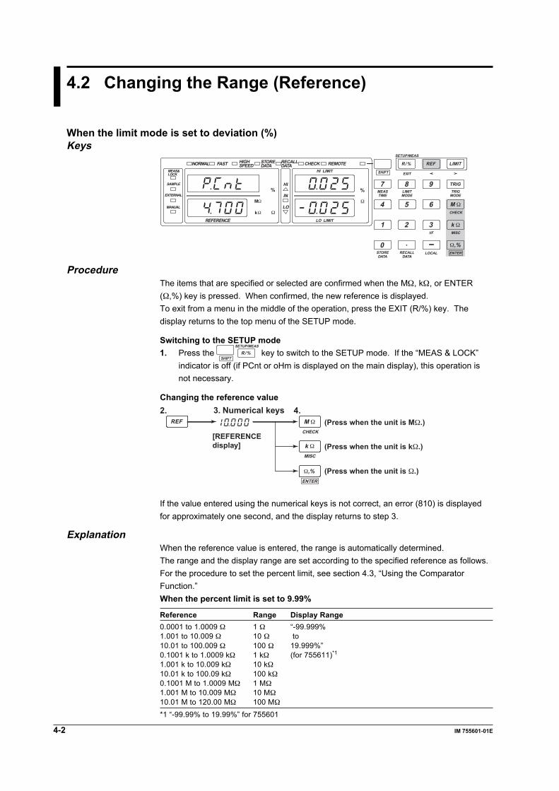
ProcedureThe items that are specified or selected are confirmed when the MΩ, kΩ, or ENTER(Ω,%) key is pressed. When confirmed, the new reference is displayed.To exit from a menu in the middle of the operation, press the EXIT (R/%) key. Thedisplay returns to the top menu of the SETUP mode.
Switching to the SETUP mode1. Press the
SHIFT
SETUP/MEAS
R/% key to switch to the SETUP mode. If the “MEAS & LOCK”indicator is off (if PCnt or oHm is displayed on the main display), this operation isnot necessary.
Changing the reference value2. 4.3. Numerical keys
(Press when the unit is MΩ.)
[REFERENCEdisplay] (Press when the unit is kΩ.)
(Press when the unit is Ω.)
CHECK
MISC
ENTER
REF M Ω
k Ω
Ω,%
If the value entered using the numerical keys is not correct, an error (810) is displayedfor approximately one second, and the display returns to step 3.
ExplanationWhen the reference value is entered, the range is automatically determined.The range and the display range are set according to the specified reference as follows.For the procedure to set the percent limit, see section 4.3, “Using the ComparatorFunction.”When the percent limit is set to 9.99%
Reference Range Display Range0.0001 to 1.0009 Ω 1 Ω “-99.999%1.001 to 10.009 Ω 10 Ω to10.01 to 100.009 Ω 100 Ω 19.999%”0.1001 k to 1.0009 kΩ 1 kΩ (for 755611)*1
1.001 k to 10.009 kΩ 10 kΩ10.01 k to 100.09 kΩ 100 kΩ0.1001 M to 1.0009 MΩ 1 MΩ1.001 M to 10.009 MΩ 10 MΩ10.01 M to 120.00 MΩ 100 MΩ
*1 “-99.99% to 19.99%” for 755601

Setting the Measurem
ent Conditions
4-3IM 755601-01E
4
When the percent limit is set to 99.9%
Reference Range Display Range0.001 to 1.009 Ω 10 Ω “-99.99%1.01 to 10.09 Ω 100 Ω to10.1 to 100.09 Ω 1 kΩ 199.99%”0.101 k to 1.009 kΩ 10 kΩ (for 755611)*2
1.01 k to 10.09 kΩ 100 kΩ10.1 k to 100.9 kΩ 1 MΩ0.101 M to 1.009 MΩ 10 MΩ1.01 M to 10.09 MΩ 100 MΩ10.1 M to 120.0 MΩ 100 MΩ
*2 “-99.9% to 199.9%” for 755601
When the limit mode is set to absolute (R)When the limit mode is set to absolute (R), the range is fixed to 1 Ω. You cannot changethis value.Maximum displayed value: 1.20000 (755611)
1.2000 (755601)Measurement resolution: 10 µ Ω (755611)
100 µ Ω (755601)
4.2 Changing the Range (Reference)

4-4 IM 755601-01E
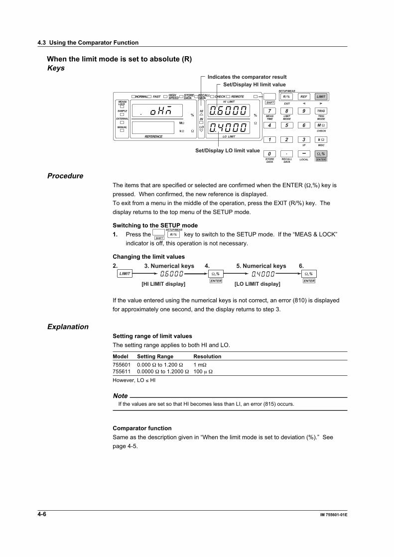
4.3 Using the Comparator Function
When the limit mode is set to deviation (%)Keys
NORMALMEAS&LOCK
SAMPLE
EXTERNAL
REFERENCE
MANUAL
FAST
HI
HI LIMITEXIT
SETUP/MEAS
CHECK
MISCI/F
MEASTIME
STOREDATA
RECALLDATA
LOCAL ENTER
LIMITMODE
TRIGMODE
SHIFT
R/% REF LIMIT
TRIG7
1
0 .
2 3
54 6
8 9
LO LIMIT
IN
LOMΩ M Ω
k Ω
Ω,%
kΩ Ω
Ω
% %
HIGHSPEED
STOREDATA
RECALLDATA CHECK REMOTE
Set/Display HI limit value
Set/Display LO limit value
Indicates the comparator result
ProcedureThe items that are specified or selected are confirmed when the ENTER (Ω,%) key ispressed. When confirmed, the new limit is displayed.To exit from a menu in the middle of the operation, press the EXIT (R/%) key. Thedisplay returns to the top menu of the SETUP mode.
Switching to the SETUP mode1. Press the
SHIFT
SETUP/MEAS
R/% key to switch to the SETUP mode. If the “MEAS & LOCK”indicator is off, this operation is not necessary.
Changing the limit value (HI and LO values)2. 4.3. Numerical keys
ENTER
Ω,%LIMIT
[HI LIMIT display]
6.5. Numerical keys
ENTER
Ω,%
[LO LIMIT display]
If the value entered using the numerical keys is not correct, an error (810) is displayedfor approximately one second, and the display returns to step 3.
Selecting the percent limit2.
4.
3.
(Plimit)
6.
5.
MISCSHIFTREF LIMIT
k Ω
REF LIMITENTER
Ω,%ENTER
Ω,%
[Main display]
[Main display]
*
*
* For 755611. For 755601, select either “9.99” or “99.9.”
Setting the Measurem
ent Conditions
4-5IM 755601-01E
4
4.3 Using the Comparator Function
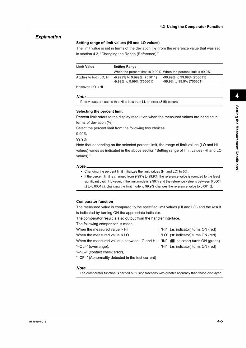
ExplanationSetting range of limit values (HI and LO values)The limit value is set in terms of the deviation (%) from the reference value that was setin section 4.3, “Changing the Range (Reference).”
Limit Value Setting RangeWhen the percent limit is 9.99% When the percent limit is 99.9%
Applies to both LO, HI -9.999% to 9.999% (755611) -99.99% to 99.99% (755611)-9.99% to 9.99% (755601) -99.9% to 99.9% (755601)
However, LO ≤ HI
NoteIf the values are set so that HI is less than LI, an error (815) occurs.
Selecting the percent limitPercent limit refers to the display resolution when the measured values are handled interms of deviation (%).Select the percent limit from the following two choices.9.99%99.9%Note that depending on the selected percent limit, the range of limit values (LO and HIvalues) varies as indicated in the above section “Setting range of limit values (HI and LOvalues).”
Note• Changing the percent limit initializes the limit values (HI and LO) to 0%.• If the percent limit is changed from 9.99% to 99.9%, the reference value is rounded to the least
significant digit. However, if the limit mode is 9.99% and the reference value is between 0.0001Ω to 0.0004 Ω, changing the limit mode to 99.9% changes the reference value to 0.001 Ω.
Comparator functionThe measured value is compared to the specified limit values (HI and LO) and the resultis indicated by turning ON the appropriate indicator.The comparator result is also output from the handler interface.The following comparison is made.When the measured value > HI : “HI” ( indicator) turns ON (red)When the measured value < LO : “LO” ( indicator) turns ON (red)When the measured value is between LO and HI : “IN” ( indicator) turns ON (green)“–OL–” (overrange), : “HI” ( indicator) turns ON (red)“–nC–” (contact check error),“–CF–” (Abnormality detected in the test current)
NoteThe comparator function is carried out using fractions with greater accuracy than those displayed.
4-6 IM 755601-01E
When the limit mode is set to absolute (R)Keys
NORMALMEAS&LOCK
SAMPLE
EXTERNAL
REFERENCE
MANUAL
FAST
HI
HI LIMITEXIT
SETUP/MEAS
CHECK
MISCI/F
MEASTIME
STOREDATA
RECALLDATA
LOCAL ENTER
LIMITMODE
TRIGMODE
SHIFT
R/% REF LIMIT
TRIG7
1
0 .
2 3
54 6
8 9
LO LIMIT
IN
LOMΩ M Ω
k Ω
Ω,%
kΩ Ω
Ω
% %
HIGHSPEED
STOREDATA
RECALLDATA CHECK REMOTE
Set/Display HI limit value
Set/Display LO limit value
Indicates the comparator result
ProcedureThe items that are specified or selected are confirmed when the ENTER (Ω,%) key ispressed. When confirmed, the new reference is displayed.To exit from a menu in the middle of the operation, press the EXIT (R/%) key. Thedisplay returns to the top menu of the SETUP mode.
Switching to the SETUP mode1. Press the
SHIFT
SETUP/MEAS
R/% key to switch to the SETUP mode. If the “MEAS & LOCK”indicator is off, this operation is not necessary.
Changing the limit values4.2. 3. Numerical keys 5. Numerical keys 6.
LIMITENTER
Ω,%ENTER
Ω,%
[HI LIMIT display] [LO LIMIT display]
If the value entered using the numerical keys is not correct, an error (810) is displayedfor approximately one second, and the display returns to step 3.
ExplanationSetting range of limit valuesThe setting range applies to both HI and LO.
Model Setting Range Resolution755601 0.000 Ω to 1.200 Ω 1 mΩ755611 0.0000 Ω to 1.2000 Ω 100 µ Ω
However, LO ≤ HI
NoteIf the values are set so that HI becomes less than LI, an error (815) occurs.
Comparator functionSame as the description given in “When the limit mode is set to deviation (%).” Seepage 4-5.
4.3 Using the Comparator Function

Setting the Measurem
ent Conditions
4-7IM 755601-01E
4
4.4 Using the Contact Check Function
Keys
NORMALMEAS&LOCK
SAMPLE
EXTERNAL
REFERENCE
MANUAL
FAST
HI
HI LIMITEXIT
SETUP/MEAS
CHECK
MISCI/F
MEASTIME
STOREDATA
RECALLDATA
LOCAL ENTER
LIMITMODE
TRIGMODE
SHIFT
R/% REF LIMIT
TRIG7
1
0 .
2 3
54 6
8 9
LO LIMIT
IN
LOMΩ M Ω
k Ω
Ω,%
kΩ Ω
Ω
% %
HIGHSPEED
STOREDATA
RECALLDATA CHECK REMOTE
Indicator is ON while contact checkis in progress
ProcedureThe items that are specified or selected are confirmed when the ENTER (Ω,%) key ispressed. When confirmed, the display returns to the top menu of the SETUP mode.To exit from a menu in the middle of the operation, press the EXIT (R/%) key. Thedisplay returns to the top menu of the SETUP mode.
Switching to the SETUP mode1. Press the
SHIFT
SETUP/MEAS
R/% key to switch to the SETUP mode. If the “MEAS & LOCK”indicator is off, this operation is not necessary.
Using the contact check2. 4.
3.
6.5. Numerical keys
(Contact check level)CHECK ENTERSHIFT
REF LIMIT
M Ω Ω,%
ENTER
Ω,%
ENTER
Ω,%
[Main display]
If the value entered using the numerical keys is not correct, an error (810) is displayedfor approximately one second, and the display returns to step 5.
ExplanationContact check functionIf the result of the contact check is larger than the specified check level, an error isgenerated. The time duration of the check is 2 ms, and the check current is 50 mA.The timing to perform the contact check can be selected from the following choices.OFF: Contact check is not performed.bEF: Contact check is performed before the measurement. If an error is detected, “–nC–” is
displayed and the “HI” indicator ( ) turns ON. “HI” “NO CONTACT” signal is outputfrom the handler interface.
AFt: Contact check is performed after the measurement. If an error is detected, “–nC–”is displayed and the “HI” indicator ( ) turns ON. “HI” “NO CONTACT” signal isoutput from the handler interface.
Setting range of the check level1 to 30 Ω (1 Ω resolution).

4-8 IM 755601-01E
4.5 Setting the Measurement Time
Keys
NORMALMEAS&LOCK
SAMPLE
EXTERNAL
REFERENCE
MANUAL
FAST
HI
HI LIMITEXIT
SETUP/MEAS
CHECK
MISCI/F
MEASTIME
STOREDATA
RECALLDATA
LOCAL ENTER
LIMITMODE
TRIGMODE
SHIFT
R/% REF LIMIT
TRIG7
1
0 .
2 3
54 6
8 9
LO LIMIT
IN
LOMΩ M Ω
k Ω
Ω,%
kΩ Ω
Ω
% %
HIGHSPEED
STOREDATA
RECALLDATA CHECK REMOTE
The appropriate indicator turns ON
ProcedureThe items that are specified or selected are confirmed when the ENTER (Ω,%) key ispressed. When confirmed, the display returns to the top menu of the SETUP mode.To exit from a menu in the middle of the operation, press the EXIT (R/%) key. Thedisplay returns to the top menu of the SETUP mode.
Switching to the SETUP mode1. Press the
SHIFT
SETUP/MEAS
R/% key to switch to the SETUP mode. If the “MEAS & LOCK”indicator is off, this operation is not necessary.
Selecting the measurement time2.
3.SHIFT
REF LIMITENTER
Ω,%
[Main display]
MEASTIME
7
ExplanationMeasurement timeSelect from the following choices.
Type Measurement Time* (when the measurement range is 1 Ω to 1 MΩ)nor (NORMAL) 19.9 ms (for 60 Hz)
23.2 ms (for 50 Hz)FASt (FAST) 5.7 msH-SP (HIGH SPEED) 2.8 ms
* Measurement time: When the trigger mode is set to EXTERNAL, the time from the triggerinput to the falling edge of the EOM signal of the handler interface iscalled the measurement time.When the trigger mode is set to Manual or Internal, the EOM signal is notoutput.When the contact check function is ON (before the measurement), add 2 ms.When the contact check function is ON (after the measurement), add 1 ms.When a trigger delay is specified, add the delay time.When the measurement range is 10 MΩ, add 4 ms.When the measurement range is 100 MΩ, add 50 ms.

Setting the Measurem
ent Conditions
4-9IM 755601-01E
4
4.6 Using the Trigger Function
KeysNORMAL
MEAS&LOCK
SAMPLE
EXTERNAL
REFERENCE
MANUAL
FAST
HI
HI LIMITEXIT
SETUP/MEAS
CHECK
MISCI/F
MEASTIME
STOREDATA
RECALLDATA
LOCAL ENTER
LIMITMODE
TRIGMODE
SHIFT
R/% REF LIMIT
TRIG7
1
0 .
2 3
54 6
8 9
LO LIMIT
IN
LOMΩ M Ω
k Ω
Ω,%
kΩ Ω
Ω
% %
HIGHSPEED
STOREDATA
RECALLDATA CHECK REMOTE
Turns ON during manual triggerTurns ON during external trigger
ProcedureThe items that are specified or selected are confirmed when the ENTER (Ω,%) key ispressed. When confirmed, the display returns to the top menu of the SETUP mode.To exit from a menu in the middle of the operation, press the EXIT (R/%) key. Thedisplay returns to the top menu of the SETUP mode.
Switching to the SETUP mode1. Press the
SHIFT
SETUP/MEAS
R/% key to switch to the SETUP mode. If the “MEAS & LOCK”indicator is off, this operation is not necessary.
Selecting the trigger mode2. 4.
3. (EXTERNAL)
(MANUAL)
(INTERNAL)
SHIFT
REF LIMITENTER
Ω,%
[Main display]
TRIGMODE
TRIG
Setting the trigger delay2.
3.MISCSHIFTREF LIMIT
k Ω
4. 6.5. Numerical keys
ENTER
Ω,%ENTER
Ω,%
[Main display]
[Main display]
If the value entered using the numerical keys is not correct, an error (810) is displayedfor approximately one second, and the display returns to step 5.
4-10 IM 755601-01E
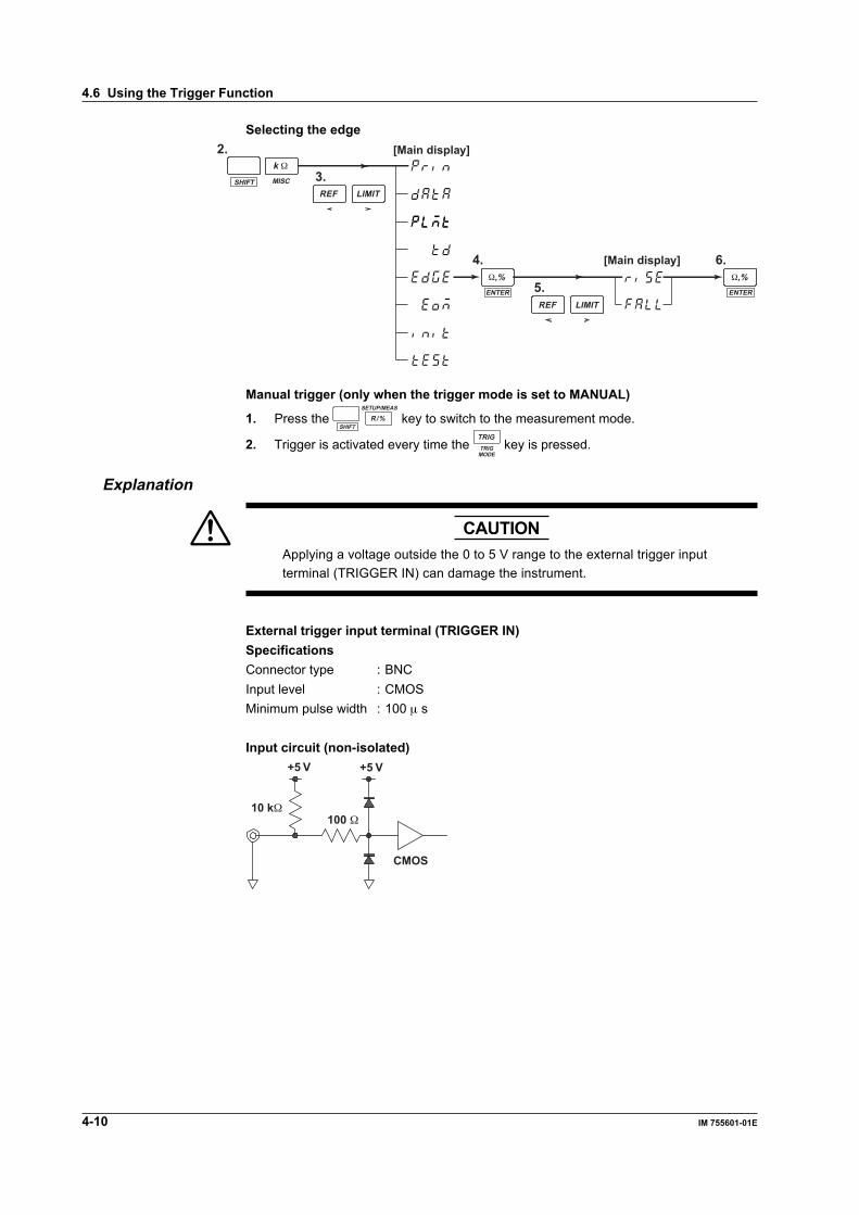
Selecting the edge
6.
5.
4.
2.
3.MISCSHIFTREF LIMIT
k Ω
REF LIMITENTER
Ω,%ENTER
Ω,%
[Main display]
[Main display]
Manual trigger (only when the trigger mode is set to MANUAL)
1. Press the SHIFT
SETUP/MEAS
R/% key to switch to the measurement mode.
2. Trigger is activated every time the TRIGMODE
TRIG key is pressed.
Explanation
CAUTIONApplying a voltage outside the 0 to 5 V range to the external trigger inputterminal (TRIGGER IN) can damage the instrument.
External trigger input terminal (TRIGGER IN)SpecificationsConnector type : BNCInput level : CMOSMinimum pulse width : 100 µ s
Input circuit (non-isolated)
10 kΩ
+5 V +5 V
100 Ω
CMOS
4.6 Using the Trigger Function
Setting the Measurem
ent Conditions
4-11IM 755601-01E
4
Selecting the trigger modeSelect from the following list of choices.EXTERNAL: Trigger is activated using the input signal at the external trigger input
terminal or the number 8 pin of the handler interface, and themeasurement is made.
MANUAL: Measurement is made when the TRIG key is pressed or when a trigger isactivated using a communication command.
INTERNAL: Measurement is made at intervals according to the specifiedmeasurement time.
Setting the trigger delayThe trigger delay setting takes effect when the trigger mode is set to EXTERNAL orMANUAL.The range and resolution are as follows:Range: 0 to 1000 msResolution: 0.1 ms
Selecting the trigger edgeThe selected edge takes effect only when the trigger mode is set to EXTERNAL.Rise (rising edge): Trigger occurs at the rising edge of the signal.Fall (falling edge): Trigger occurs at the falling edge of the signal.
Measurement interval for INTERNAL (internal trigger)When the trigger mode is set to INTERNAL, the measurement interval is set to thefollowing values depending on the specified measurement time.
Measurement Time Measurement IntervalNORMAL 50 msFAST 20 msHIGH SPEED 10 msHowever, the measurement interval is adjusted by adding the appropriate values for the followingcases: 5/10/15 ms when the pulse width of the EOM signal of the handler interface is set to 5/10/15 ms, respectively, 5 ms when the contact check function is ON, 5 ms when the range is 10 MΩ,and 50 ms when the range is 100 MΩ.
4.6 Using the Trigger Function

Making M
easurements
5-1IM 755601-01E
5
Chapter 5 Making Measurements
LOCAL keyGP-IB connector
5.1 Setting the Measurement Mode
Keys
NORMALMEAS&LOCK
SAMPLE
EXTERNAL
REFERENCE
MANUAL
FAST
HI
HI LIMITEXIT
SETUP/MEAS
CHECK
MISCI/F
MEASTIME
STOREDATA
RECALLDATA
LOCAL ENTER
LIMITMODE
TRIGMODE
SHIFT
R/% REF LIMIT
TRIG7
1
0 .
2 3
54 6
8 9
LO LIMIT
IN
LOMΩ M Ω
k Ω
Ω,%
kΩ Ω
Ω
% %
HIGHSPEED
STOREDATA
RECALLDATA CHECK REMOTE
Displays the measured valueIndicator is ON during the measurement mode
Blinks every data sample
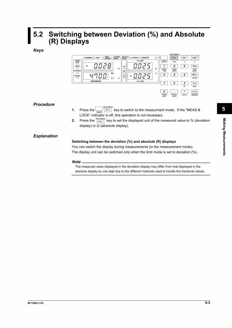
ProcedurePress the
SHIFT
SETUP/MEAS
R/% key to switch to the measurement mode. If the “MEAS & LOCK”indicator is off, this operation is not necessary.
ExplanationIn the measurement mode, measurements are made according to the various specifiedsettings such as the trigger mode, measurement time, and range. The measured valueis displayed using seven-segment digital characters.You can not change the settings in the measurement mode.The following keys can be used in the measurement mode.• SETUP/MEAS (SHIFT+R/%) key: Used to switch between the measurement and
SETUP modes.• TRIG key: Pressing this key when the trigger mode is set to
MANUAL activates a trigger.• R/% key: Used to switch the display when the limit mode is
set to deviation (%).• STORE DATA (SHIFT+0) key: Pressing this key while making measurements
causes the “STORE DATA” indicator to turn ONand the instrument to enter a state in which datacan be stored. Pressing this key while theinstrument is storing data terminates the storeoperation.
• RECALL DATA (SHIFT+ .) key: Pressing this key while the instrument is recallingdata (“RECALL DATA” indicator is ON)terminates the recall operation.
The error displays for measured values are as follows:• When the value is over the range:• When a contact check error occurs:• When abnormalities are detected in the test current:For details regarding the error displays, see page 2-4.
5-2 IM 755601-01E
5.1 Setting the Measurement Mode
Precautions to be taken during measurementPrecautions on the “HOLD” signal of the handler interfaceWhen the HOLD signal of the handler interface is set to “L,” the instrument switches tothe measurement mode regardless of the mode it is currently in (the trigger mode is setto EXTERNAL), and makes measurements. Since the SETUP/MEAS key is locked, youwill not be able to switch modes using the key. If you wish to do so, first, set the HOLDsignal to “H,” then change the mode using the key or a communication command.Simply changing the HOLD signal from “L” to “H” does not change the mode. Themeasurement continues in this case.
NoteUse the SETUP mode to change the reference value and limit values.
Precautions to be taken when using the trigger input signalWhen activating the trigger with the input signal applied to the external trigger inputterminal on the rear panel or the number 8 pin of the handler interface (EXT TRIG), theunused terminal or pin must be set to open or HI level. Otherwise, the trigger will notfunction.
Making M
easurements
5-3IM 755601-01E
5
5.2 Switching between Deviation (%) and Absolute(R) Displays
KeysNORMAL
MEAS&LOCK
SAMPLE
EXTERNAL
REFERENCE
MANUAL
FAST
HI
HI LIMITEXIT
SETUP/MEAS
CHECK
MISCI/F
MEASTIME
STOREDATA
RECALLDATA
LOCAL ENTER
LIMITMODE
TRIGMODE
SHIFT
R/% REF LIMIT
TRIG7
1
0 .
2 3
54 6
8 9
LO LIMIT
IN
LOMΩ M Ω
k Ω
Ω,%
kΩ Ω
Ω
% %
HIGHSPEED
STOREDATA
RECALLDATA CHECK REMOTE
Procedure1. Press the
SHIFT
SETUP/MEAS
R/% key to switch to the measurment mode. If the “MEAS &LOCK” indicator is off, this operation is not necessary.
2. Press the SETUP/MEAS
R/% key to set the displayed unit of the measured value to % (deviationdisplay) or Ω (absolute display).
ExplanationSwitching between the deviation (%) and absolute (R) displaysYou can switch the display during measurements (in the measurement mode).The display unit can be switched only when the limit mode is set to deviation (%).
NoteThe measured value displayed in the deviation display may differ from that displayed in theabsolute display by one digit due to the different methods used to handle the fractional values.
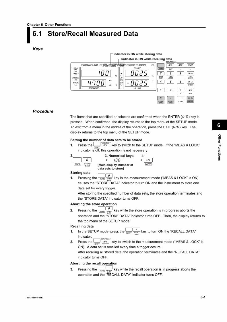
Other Functions
6-1IM 755601-01E
6
Chapter 6 Other Functions
LOCAL keyGP-IB connector
6.1 Store/Recall Measured Data
Keys
NORMALMEAS&LOCK
SAMPLE
EXTERNAL
REFERENCE
MANUAL
FAST
HI
HI LIMITEXIT
SETUP/MEAS
CHECK
MISCI/F
MEASTIME
STOREDATA
RECALLDATA
LOCAL ENTER
LIMITMODE
TRIGMODE
SHIFT
R/% REF LIMIT
TRIG7
1
0 .
2 3
54 6
8 9
LO LIMIT
IN
LOMΩ M Ω
k Ω
Ω,%
kΩ Ω
Ω
% %
HIGHSPEED
STOREDATA
RECALLDATA CHECK REMOTE
Indicator is ON while storing dataIndicator is ON while recalling data
ProcedureThe items that are specified or selected are confirmed when the ENTER (Ω,%) key ispressed. When confirmed, the display returns to the top menu of the SETUP mode.To exit from a menu in the middle of the operation, press the EXIT (R/%) key. Thedisplay returns to the top menu of the SETUP mode.
Setting the number of data sets to be stored1. Press the
SHIFT
SETUP/MEAS
R/% key to switch to the SETUP mode. If the “MEAS & LOCK”indicator is off, this operation is not necessary.
[Main display, number ofdata sets to store]
4.3. Numerical keys2.
SHIFT ENTER
Ω,%STOREDATA
0
Storing data1. Pressing the SHIFT STORE
DATA
0 key in the measurement mode (“MEAS & LOCK” is ON)
causes the “STORE DATA” indicator to turn ON and the instrument to store onedata set for every trigger.After storing the specified number of data sets, the store operation terminates andthe “STORE DATA” indicator turns OFF.
Aborting the store operation
2. Pressing the SHIFT STOREDATA
0 key while the store operation is in progress aborts theoperation and the “STORE DATA” indicator turns OFF. Then, the display returns tothe top menu of the SETUP mode.
Recalling data1. In the SETUP mode, press the SHIFT RECALL
DATA
. key to turn ON the “RECALL DATA”
indicator.2. Press the
SHIFT
SETUP/MEAS
R/% key to switch to the measurement mode (“MEAS & LOCK” isON). A data set is recalled every time a trigger occurs.After recalling all stored data, the operation terminates and the “RECALL DATA”indicator turns OFF.
Aborting the recall operation3. Pressing the SHIFT RECALL
DATA
. key while the recall operation is in progress aborts the
operation and the “RECALL DATA” indicator turns OFF.

6-2 IM 755601-01E
6.1 Store/Recall Measured Data
Note• Pressing the STORE DATA (SHIFT+0) key in the measurement mode while the store
operation is in progress (“STORE DATA” indicator is ON) aborts the operation and continuesthe measurement.
• Pressing the RECALL DATA (SHIFT+ .) key while the recall operation is in progress(“RECALL DATA” indicator is ON) aborts the operation and continues the measurement.
ExplanationStoring measured dataUp to 2000 measured data sets can be stored in the internal memory. The data arecleared when the power is turned OFF or the settings are initialized. By using theoptional Centronics interface, statistics on the stored data can be computed and printedto an external printer. For the procedures related to printing, see section 6.2.
Timing used to store or recall dataWhen the “STORE DATA” or “RECALL DATA” indicator is ON in the measurementmode, measured data are stored or recalled every time a trigger occurs.The timing used to store or recall data varies depending on the trigger mode as follows:EXTERNAL: Data are stored or recalled when a trigger is activated using the input
signal at the external trigger input terminal or the number 8 pin of thehandler interface.
MANUAL: Data are stored or recalled when the TRIG key is pressed or when atrigger is activated using a communication command.
INTERNAL: Data are stored or recalled at measurement intervals according to thespecified measurement time. For details regarding the measurementinterval, see page 4-11.
Precautions to be taken when storing data• The STORE DATA (SHIFT+0) key can be used even in the measurement mode
(when the measurement is in progress).• Executing a store operation, clears the previously stored data.• Data cannot be stored when the “RECALL DATA” indicator is ON. An error (831) is
displayed in this case.• When the store operation is aborted, data stored up to that point can be recalled.
Precautions to be taken when recalling data• Data are recalled in order from the first data in the memory. After recalling all of the
data, the instrument continues the measurement.• Data cannot be recalled when the “STORE DATA” indicator is ON. An error (832) is
displayed in this case.• If there are no stored data in the memory, an error (830) is displayed for
approximately one second, and the display returns to the top menu of the SETUPmode.
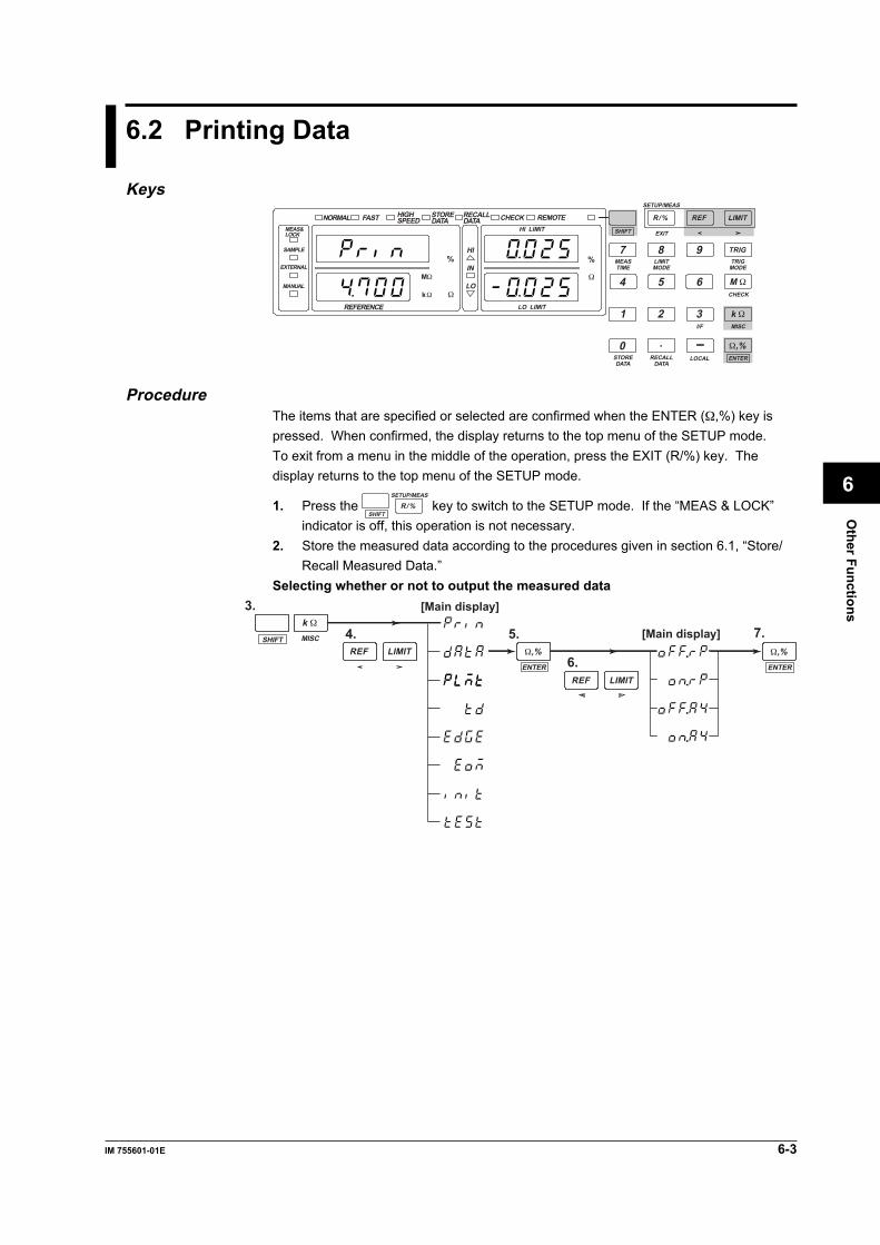
Other Functions
6-3IM 755601-01E
6
6.2 Printing Data
KeysNORMAL
MEAS&LOCK
SAMPLE
EXTERNAL
REFERENCE
MANUAL
FAST
HI
HI LIMITEXIT
SETUP/MEAS
CHECK
MISCI/F
MEASTIME
STOREDATA
RECALLDATA
LOCAL ENTER
LIMITMODE
TRIGMODE
SHIFT
R/% REF LIMIT
TRIG7
1
0 .
2 3
54 6
8 9
LO LIMIT
IN
LOMΩ M Ω
k Ω
Ω,%
kΩ Ω
Ω
% %
HIGHSPEED
STOREDATA
RECALLDATA CHECK REMOTE
ProcedureThe items that are specified or selected are confirmed when the ENTER (Ω,%) key ispressed. When confirmed, the display returns to the top menu of the SETUP mode.To exit from a menu in the middle of the operation, press the EXIT (R/%) key. Thedisplay returns to the top menu of the SETUP mode.
1. Press the SHIFT
SETUP/MEAS
R/% key to switch to the SETUP mode. If the “MEAS & LOCK”indicator is off, this operation is not necessary.
2. Store the measured data according to the procedures given in section 6.1, “Store/Recall Measured Data.”
Selecting whether or not to output the measured data
6.
5. 7.
3.
4.MISCSHIFTREF LIMIT
k Ω
REF LIMITENTER
Ω,%ENTER
Ω,%
[Main display]
[Main display]

6-4 IM 755601-01E
Start/Stop printing5. 7.
6.
3.
4.MISCSHIFTREF LIMIT
k Ω
REF LIMITENTER
Ω,%
ENTER
Ω,%
ENTER
Ω,%
(Indicates that dataare being transferredto the printer)
(Abort printing)
[Main display] [Main display]
ExplanationBy using the optional Centronics interface, statistics on the stored data can be computedand printed to an external printer.
CAUTIONUse a Centronics printer cable to connect an external printer to theinstrument. A bad connection can damage the instrument and/or otherdevices that are connected to it.
Pin arrangement of the Centronics interface connectorPin No.12
9101112131415161718
SignalSTROBE (Strobe)DATA0 (Print data bit 0)
DATA7 (Print data bit 7)ACK (Acknowledge)BUSY (Busy)PE (Paper end)SLCT (Select)NC (No connection)NC (No connection)GND (Ground)GND (Ground)NC (No connection)
Pin No.19
30313233343536
SignalGND (Ground)
GND (Ground)INIT (Initialize printer)ERROR (Error)GND (Ground)NC (No connection)NC (No connection)NC (No connection)
1
19
18
36
Pin No.
For details, contact your nearestYOKOGAWA dealer.
6.2 Printing Data
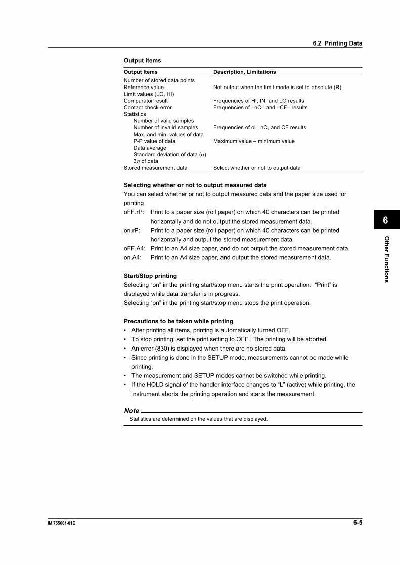
Other Functions
6-5IM 755601-01E
6
Output items
Output Items Description, LimitationsNumber of stored data pointsReference value Not output when the limit mode is set to absolute (R).Limit values (LO, HI)Comparator result Frequencies of HI, IN, and LO resultsContact check error Frequencies of –nC– and –CF– resultsStatistics
Number of valid samplesNumber of invalid samples Frequencies of oL, nC, and CF resultsMax. and min. values of dataP-P value of data Maximum value – minimum valueData averageStandard deviation of data (σ)3σ of data
Stored measurement data Select whether or not to output data
Selecting whether or not to output measured dataYou can select whether or not to output measured data and the paper size used forprintingoFF.rP: Print to a paper size (roll paper) on which 40 characters can be printed
horizontally and do not output the stored measurement data.on.rP: Print to a paper size (roll paper) on which 40 characters can be printed
horizontally and output the stored measurement data.oFF.A4: Print to an A4 size paper, and do not output the stored measurement data.on.A4: Print to an A4 size paper, and output the stored measurement data.
Start/Stop printingSelecting “on” in the printing start/stop menu starts the print operation. “Print” isdisplayed while data transfer is in progress.Selecting “on” in the printing start/stop menu stops the print operation.
Precautions to be taken while printing• After printing all items, printing is automatically turned OFF.• To stop printing, set the print setting to OFF. The printing will be aborted.• An error (830) is displayed when there are no stored data.• Since printing is done in the SETUP mode, measurements cannot be made while
printing.• The measurement and SETUP modes cannot be switched while printing.• If the HOLD signal of the handler interface changes to “L” (active) while printing, the
instrument aborts the printing operation and starts the measurement.
NoteStatistics are determined on the values that are displayed.
6.2 Printing Data

6-6 IM 755601-01E
Print example
6.2 Printing Data

Other Functions
6-7IM 755601-01E
6
6.3 Initializing the Setup Information
KeysNORMAL
MEAS&LOCK
SAMPLE
EXTERNAL
REFERENCE
MANUAL
FAST
HI
HI LIMITEXIT
SETUP/MEAS
CHECK
MISCI/F
MEASTIME
STOREDATA
RECALLDATA
LOCAL ENTER
LIMITMODE
TRIGMODE
SHIFT
R/% REF LIMIT
TRIG7
1
0 .
2 3
54 6
8 9
LO LIMIT
IN
LOMΩ M Ω
k Ω
Ω,%
kΩ Ω
Ω
% %
HIGHSPEED
STOREDATA
RECALLDATA CHECK REMOTE
ProcedureInitializing the settingsThe items that are specified or selected are confirmed when the ENTER (Ω,%) key ispressed. When confirmed, the display returns to the top menu of the SETUP mode.To exit from a menu in the middle of the operation, press the EXIT (R/%) key. Thedisplay returns to the top menu of the SETUP mode.
1. Press the SHIFT
SETUP/MEAS
R/% key to switch to the SETUP mode. If the “MEAS & LOCK”indicator is off, this operation is not necessary.
2.
3.
4.
MISCSHIFTREF LIMIT
k Ω
ENTER
Ω,%
[Main display]
Resetting the instrument to the factory default settingsTurn ON the power switch on the rear panel while pressing the
SHIFT key. Keep pressing
the SHIFT key until the top menu appears on the screen.
ExplanationThe setup information can be set to “initial settings” or “factory default settings.” This actis called initializing.Initializing the setup information does not initialize settings related to communications.For details related to the initializing of the setup information, see section 1.4, “A List ofInitial Values.”
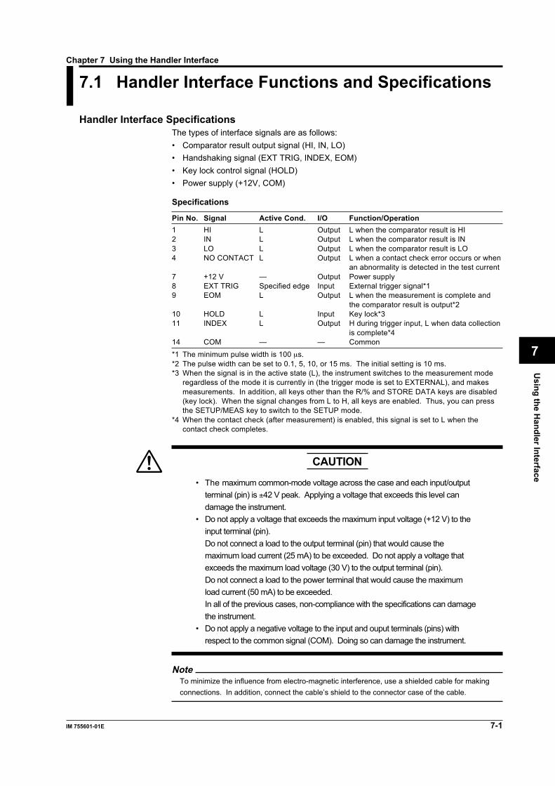
Using the H
andler Interface
7-1IM 755601-01E
7
Chapter 7 Using the Handler Interface
LOCAL keyGP-IB connector
7.1 Handler Interface Functions and Specifications
Handler Interface SpecificationsThe types of interface signals are as follows:• Comparator result output signal (HI, IN, LO)• Handshaking signal (EXT TRIG, INDEX, EOM)• Key lock control signal (HOLD)• Power supply (+12V, COM)
Specifications
Pin No. Signal Active Cond. I/O Function/Operation1 HI L Output L when the comparator result is HI2 IN L Output L when the comparator result is IN3 LO L Output L when the comparator result is LO4 NO CONTACT L Output L when a contact check error occurs or when
an abnormality is detected in the test current7 +12 V — Output Power supply8 EXT TRIG Specified edge Input External trigger signal*19 EOM L Output L when the measurement is complete and
the comparator result is output*210 HOLD L Input Key lock*311 INDEX L Output H during trigger input, L when data collection
is complete*414 COM — — Common*1 The minimum pulse width is 100 µs.*2 The pulse width can be set to 0.1, 5, 10, or 15 ms. The initial setting is 10 ms.*3 When the signal is in the active state (L), the instrument switches to the measurement mode
regardless of the mode it is currently in (the trigger mode is set to EXTERNAL), and makesmeasurements. In addition, all keys other than the R/% and STORE DATA keys are disabled(key lock). When the signal changes from L to H, all keys are enabled. Thus, you can pressthe SETUP/MEAS key to switch to the SETUP mode.
*4 When the contact check (after measurement) is enabled, this signal is set to L when thecontact check completes.
CAUTION
• The maximum common-mode voltage across the case and each input/outputterminal (pin) is ±42 V peak. Applying a voltage that exceeds this level candamage the instrument.
• Do not apply a voltage that exceeds the maximum input voltage (+12 V) to theinput terminal (pin).Do not connect a load to the output terminal (pin) that would cause themaximum load current (25 mA) to be exceeded. Do not apply a voltage thatexceeds the maximum load voltage (30 V) to the output terminal (pin).Do not connect a load to the power terminal that would cause the maximumload current (50 mA) to be exceeded.In all of the previous cases, non-compliance with the specifications can damagethe instrument.
• Do not apply a negative voltage to the input and ouput terminals (pins) withrespect to the common signal (COM). Doing so can damage the instrument.
NoteTo minimize the influence from electro-magnetic interference, use a shielded cable for makingconnections. In addition, connect the cable’s shield to the connector case of the cable.

7-2 IM 755601-01E
7.1 Handler Interface Functions and Specifications
Output Signal BehaviorThe behavior of the INDEX, EOM, NO CONTACT, HI, IN, and LO output signals variesdepending on the trigger mode as follows:When the trigger mode is set to EXTERNALINDEX: The signal is generated (set to L) when a trigger occurs, regardless of
the measurement result.EOM: The signal is generated (set to L) when the measurement completes
once, regardless of the measurement result.NO CONTACT: The signal is generated (set to L) when the measurement results in a
contact check error (nC) or when the test current is abnormal (CF).HI: The signal is generated (set to L) when the comparator result of the
measured value is HI.The signal is also generated (set to L) when the measurement resultsin over-range (oL), contact check error (nC), or when the test current isabnormal (CF).
IN: The signal is generated (set to L) when the comparator result of themeasured value is IN.
LO: The signal is generated (set to L) when the comparator result of themeasured value is LO.
When the trigger mode is set to MANUAL or INTERNALINDEX: The signal is not generated (stays at H).EOM: The signal is not generated (stays at H).NO CONTACT: The signal is generated (set to L) when the measurement results in a
contact check error (nC) or when the test current is abnormal (CF).HI: The signal is generated (set to L) when the comparator result of the
measured value is HI.The signal is also generated (set to L) when the measurement resultsin over-range (oL), contact check error (nC), or when the test current isabnormal (CF).
IN: The signal is generated (set to L) when the comparator result of themeasured value is IN.
LO: The signal is generated (set to L) when the comparator result of themeasured value is LO.
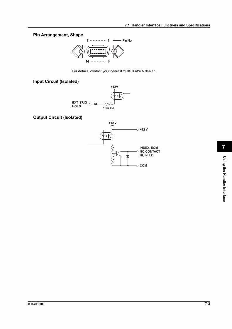
Using the H
andler Interface
7-3IM 755601-01E
7
Pin Arrangement, Shape1 Pin No.7
814
For details, contact your nearest YOKOGAWA dealer.
Input Circuit (Isolated)
1.65 kΩ
+12V
EXT TRIGHOLD
Output Circuit (Isolated)+12 V
+12 V
COM
INDEX, EOMNO CONTACTHI, IN, LO
7.1 Handler Interface Functions and Specifications
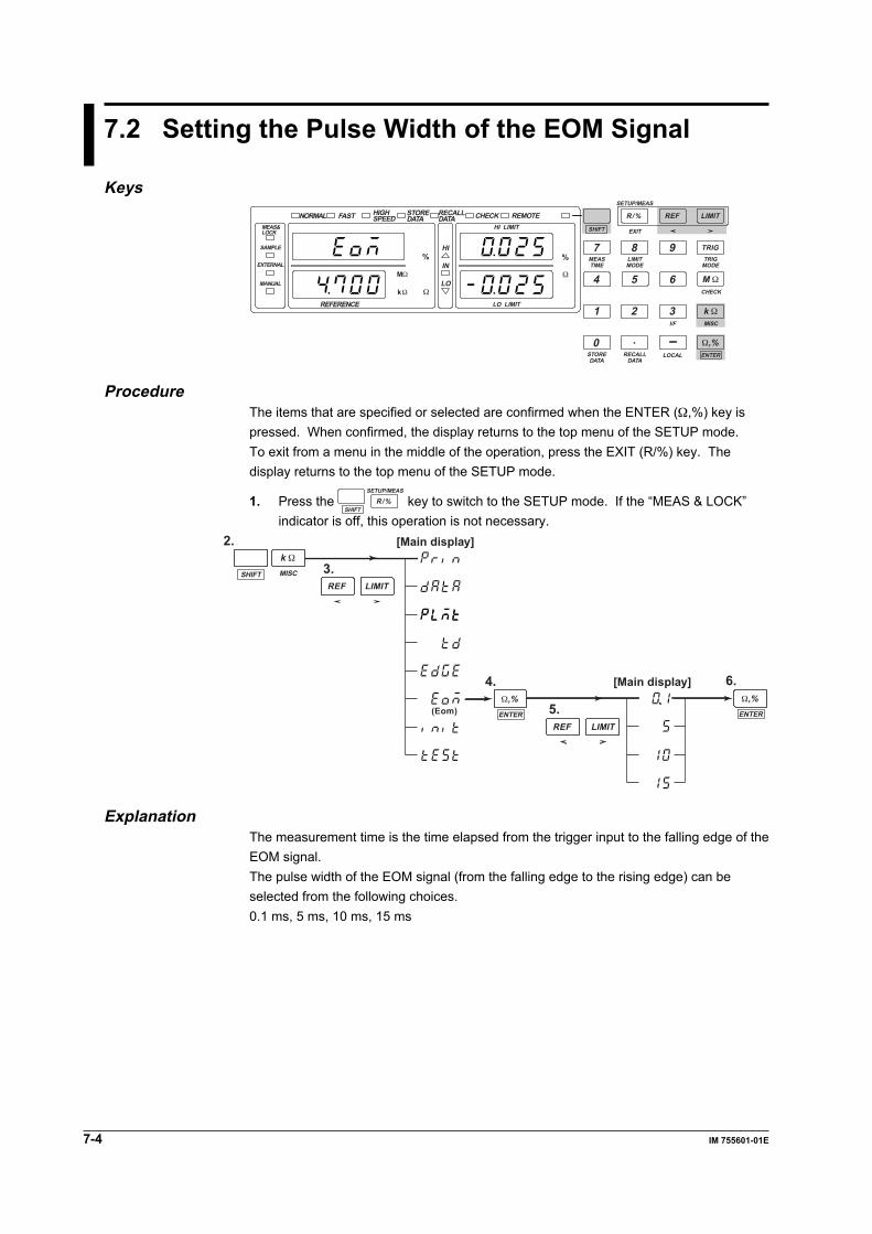
7-4 IM 755601-01E
7.2 Setting the Pulse Width of the EOM Signal
KeysNORMAL
MEAS&LOCK
SAMPLE
EXTERNAL
REFERENCE
MANUAL
FAST
HI
HI LIMITEXIT
SETUP/MEAS
CHECK
MISCI/F
MEASTIME
STOREDATA
RECALLDATA
LOCAL ENTER
LIMITMODE
TRIGMODE
SHIFT
R/% REF LIMIT
TRIG7
1
0 .
2 3
54 6
8 9
LO LIMIT
IN
LOMΩ M Ω
k Ω
Ω,%
kΩ Ω
Ω
% %
HIGHSPEED
STOREDATA
RECALLDATA CHECK REMOTE
ProcedureThe items that are specified or selected are confirmed when the ENTER (Ω,%) key ispressed. When confirmed, the display returns to the top menu of the SETUP mode.To exit from a menu in the middle of the operation, press the EXIT (R/%) key. Thedisplay returns to the top menu of the SETUP mode.
1. Press the SHIFT
SETUP/MEAS
R/% key to switch to the SETUP mode. If the “MEAS & LOCK”indicator is off, this operation is not necessary.
4.
5.
2.
3.
(Eom)
6.
MISCSHIFTREF LIMIT
k Ω
REF LIMITENTER
Ω,%ENTER
Ω,%
[Main display]
[Main display]
ExplanationThe measurement time is the time elapsed from the trigger input to the falling edge of theEOM signal.The pulse width of the EOM signal (from the falling edge to the rising edge) can beselected from the following choices.0.1 ms, 5 ms, 10 ms, 15 ms
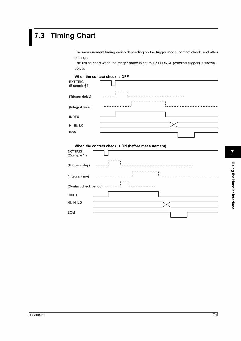
Using the H
andler Interface
7-5IM 755601-01E
7
7.3 Timing Chart
The measurement timing varies depending on the trigger mode, contact check, and othersettings.The timing chart when the trigger mode is set to EXTERNAL (external trigger) is shownbelow.
When the contact check is OFFEXT TRIG(Example )
INDEX
HI, IN, LO
EOM
(Trigger delay)
(Integral time)
When the contact check is ON (before measurement)
(Contact check period)
EXT TRIG(Example )
INDEX
HI, IN, LO
EOM
(Trigger delay)
(Integral time)

7-6 IM 755601-01E
7.3 Timing Chart
When the contact check is ON (after measurement)
(Contact check period)
EXT TRIG(Example )
INDEX
HI, IN, LO
EOM
(Trigger delay)
(Integral time)

Using the Serial (R
S-232) Interface
8-1IM 755601-01E
8
Chapter 8 Using the Serial (RS-232) Interface
LOCAL keyGP-IB connector
8.1 Serial (RS-232) Interface Functions andSpecifications
Receiving FunctionAll of the parameters that you set with the panel keys can be set through the serial interfaceexcept turning the power switch ON/OFF and setting the communication parameters.Output requests for measured/statistical data, setup information, and error codes can bealso be received through the serial interface.
Sending FunctionMeasured/statistical data can be output.Setup information and status byte can be output.Error codes that have occurred can be output.
RS-232 Interface SpecificationsElectrical, mechanical characteristics: Conforms to the EIA-574 standard (for the 9-pin
interface of the EIA-232 (RS-232) standard)Connection: Point-to-pointCommunication: Full-duplexSynchronization: Start-stop synchronizationBaud rate: 1200, 2400, 4800, 9600, 19200Start bit: 1 bit (fixed)Data length: 7 or 8 bitsParity: Even, odd, noneStop bit: 1 or 2 bitsConnector: For details contact your nearest YOKOGAWA dealer.Hardware handshaking: User can select whether to fix the CA and CB
signals to TRUE or use the signal for flow control.Software handshaking: User can select whether to use the X-ON and X-
OFF signals to control only the transmitted dataor both transmitted and received data.X-ON (ASCII 11H)X-OFF (ASCII 13H)Received buffer size: 256 bytes
Switching between Remote and Local ModesWhen switching from local to remote modeReceiving a “:COMMunicate:REMote ON” command from a PC when the instrument is inthe local mode causes the instrument to switch to the remote mode.• The “REMOTE” indicator turns ON.• All keys other than the LOCAL key are locked.• The settings that existed in the local mode are maintained even when the instrument
switches to the remote mode.When switching from remote to local modePressing the LOCAL key when the instrument is in the remote mode causes the instrumentto switch to the local mode. However, this act produces no result if the “:COMMunicate:LOCKout ON” command has been received from the PC (local lockout condition).When the “:COMMunicate:REMote OFF” is received from the PC, the instrument switchesto the local mode regardless of the local lockout condition.• “REMOTE” indicator turns OFF.• Key operations are enabled.• The settings that existed in the remote mode are maintained even when the
instrument switches to the local mode.

8-2 IM 755601-01E
8.2 Connecting the Serial (RS-232) Interface Cable
When connecting this instrument to a PC, make sure the handshaking methods, datatransmission rates, and data formats match those selected on the PC.For details, see the following pages. Also, make sure to use interface cables that matchthe specifications of the instrument.
Connector and Signal Names
For details contact your nearest YOKOGAWA dealer.
21 3 4 5
6 7 8 9
2 RD (Received Data): Data received from the PC.Signal direction: Input
3 SD (Send Data): Data transmitted to the PC.Signal direction: Output
5 SG (Signal Ground): Ground for signals.7 RS (Request to Send): Signal used for handshaking when receiving data from the PC.
Signal direction: Output8 CS (Clear to Send): Signal used for handshaking when transmitting data to the PC.
Signal direction: Input* Pins 1, 4, 6, and 9 are not used.
9-25 Pin Connector and Signal Names
58723(2) (3)(4) (5) (7)
The numbers in parentheses corresponds to the pin numbers on the 25-pin connector.
Signal DirectionThe figure below shows the directions of the signals used by the RS-232 interface of thisinstrument.
PC 755601/755611
RS [Request to send]
SD [Send data]RD [Receive data] 2
3 8 7
CS [Clear to send]
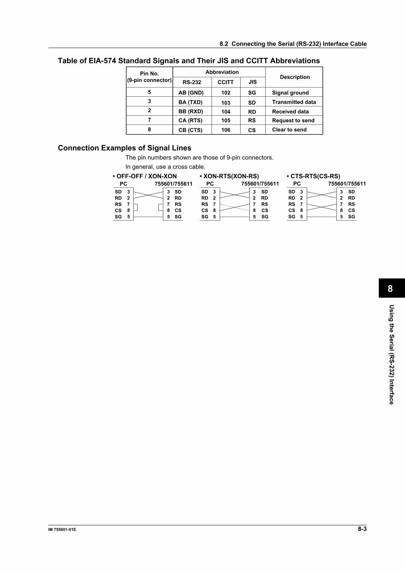
Using the Serial (R
S-232) Interface
8-3IM 755601-01E
8
8.2 Connecting the Serial (RS-232) Interface Cable
Table of EIA-574 Standard Signals and Their JIS and CCITT AbbreviationsPin No.
(9-pin connector)Abbreviation
RS-232Description
CCITT JIS
532
8
7
AB (GND)
BA (TXD)BB (RXD)
CB (CTS)
CA (RTS)
102 SG
103104
106
105
SDRD
CS
RS
Signal groundTransmitted data
Request to sendReceived data
Clear to send
Connection Examples of Signal LinesThe pin numbers shown are those of 9-pin connectors.In general, use a cross cable.
SDRDRSCSSG
SDRDRS
SG
• OFF-OFF / XON-XONPC 755601/755611
SDRDRSCSSG
SDRDRS
SG
• XON-RTS(XON-RS)PC 755601/755611
SDRDRSCSSG
SDRDRS
SG
• CTS-RTS(CS-RS)PC 755601/755611
CS CS CS
2 3
8 7
5
2 3
8 7
5
2 3
8 7
5
2 3
8 7
5
2 3
8 7
5
2 3
8 7
5
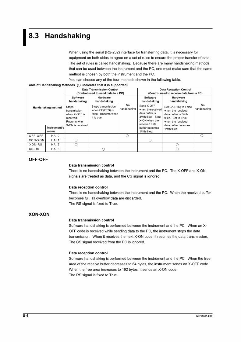
8-4 IM 755601-01E
8.3 Handshaking
When using the serial (RS-232) interface for transferring data, it is necessary forequipment on both sides to agree on a set of rules to ensure the proper transfer of data.The set of rules is called handshaking. Because there are many handshaking methodsthat can be used between the instrument and the PC, one must make sure that the samemethod is chosen by both the instrument and the PC.You can choose any of the four methods shown in the following table.
Data Transmission Control(Control used to send data to a PC)
Data Reception Control(Control used to receive data from a PC)
Softwarehandshaking
Softwarehandshaking
Table of Handshaking Methods ( indicates that it is supported)
HA. 0HA. 1HA. 2HA. 3
OFF-OFFXON-XONXON-RSCS-RS
Handshaking method Stopstransmissionwhen X-OFF isreceived. Resume whenX-ON is received.
Stops transmissionwhen CB(CTS) isfalse. Resume whenit is true.
Nohandshaking
Nohandshaking
Send X-OFFwhen thereceiveddata buffer is3/4th filled. SendX-ON when thereceived databuffer becomes1/4th filled.
Set CA(RTS) to Falsewhen the receiveddata buffer is 3/4thfilled. Set to Truewhen the receiveddata buffer becomes1/4th filled.
Hardwarehandshaking
Hardwarehandshaking
Instrument'smenu
OFF-OFFData transmission controlThere is no handshaking between the instrument and the PC. The X-OFF and X-ONsignals are treated as data, and the CS signal is ignored.
Data reception controlThere is no handshaking between the instrument and the PC. When the received bufferbecomes full, all overflow data are discarded.The RS signal is fixed to True.
XON-XONData transmission controlSoftware handshaking is performed between the instrument and the PC. When an X-OFF code is received while sending data to the PC, the instrument stops the datatransmission. When it receives the next X-ON code, it resumes the data transmission.The CS signal received from the PC is ignored.
Data reception controlSoftware handshaking is performed between the instrument and the PC. When the freearea of the receive buffer decreases to 64 bytes, the instrument sends an X-OFF code.When the free area increases to 192 bytes, it sends an X-ON code.The RS signal is fixed to True.
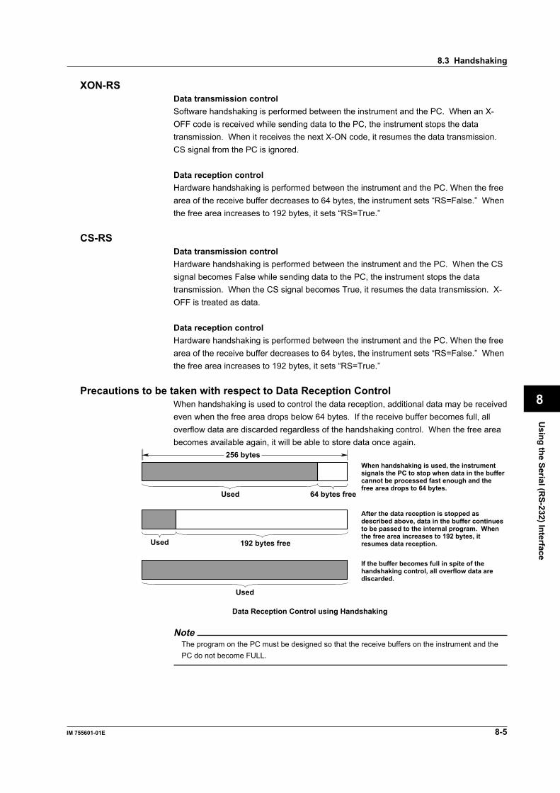
Using the Serial (R
S-232) Interface
8-5IM 755601-01E
8
XON-RSData transmission controlSoftware handshaking is performed between the instrument and the PC. When an X-OFF code is received while sending data to the PC, the instrument stops the datatransmission. When it receives the next X-ON code, it resumes the data transmission.CS signal from the PC is ignored.
Data reception controlHardware handshaking is performed between the instrument and the PC. When the freearea of the receive buffer decreases to 64 bytes, the instrument sets “RS=False.” Whenthe free area increases to 192 bytes, it sets “RS=True.”
CS-RSData transmission controlHardware handshaking is performed between the instrument and the PC. When the CSsignal becomes False while sending data to the PC, the instrument stops the datatransmission. When the CS signal becomes True, it resumes the data transmission. X-OFF is treated as data.
Data reception controlHardware handshaking is performed between the instrument and the PC. When the freearea of the receive buffer decreases to 64 bytes, the instrument sets “RS=False.” Whenthe free area increases to 192 bytes, it sets “RS=True.”
Precautions to be taken with respect to Data Reception ControlWhen handshaking is used to control the data reception, additional data may be receivedeven when the free area drops below 64 bytes. If the receive buffer becomes full, alloverflow data are discarded regardless of the handshaking control. When the free areabecomes available again, it will be able to store data once again.
256 bytes
Used 64 bytes free
When handshaking is used, the instrument signals the PC to stop when data in the buffer cannot be processed fast enough and the free area drops to 64 bytes.
Used 192 bytes free
After the data reception is stopped as described above, data in the buffer continues to be passed to the internal program. When the free area increases to 192 bytes, it resumes data reception.
Used
If the buffer becomes full in spite of the handshaking control, all overflow data are discarded.
Data Reception Control using Handshaking
NoteThe program on the PC must be designed so that the receive buffers on the instrument and thePC do not become FULL.
8.3 Handshaking
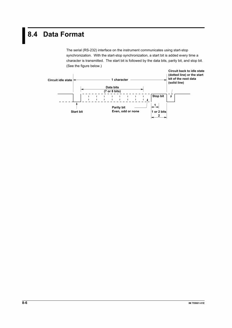
8-6 IM 755601-01E
8.4 Data Format
The serial (RS-232) interface on the instrument communicates using start-stopsynchronization. With the start-stop synchronization, a start bit is added every time acharacter is transmitted. The start bit is followed by the data bits, parity bit, and stop bit.(See the figure below.)
Data bits(7 or 8 bits)
1 character
Stop bit
1
1 or 2 bits2
Parity bitEven, odd or noneStart bit
Circuit idle state
Circuit back to idle state(dotted line) or the startbit of the next data(solid line)

Using the Serial (R
S-232) Interface
8-7IM 755601-01E
8
8.5 Serial Communication Settings
Keys
NORMALMEAS&LOCK
SAMPLE
EXTERNAL
REFERENCE
MANUAL
FAST
HI
HI LIMITEXIT
SETUP/MEAS
CHECK
MISCI/F
MEASTIME
STOREDATA
RECALLDATA
LOCAL ENTER
LIMITMODE
TRIGMODE
SHIFT
R/% REF LIMIT
TRIG7
1
0 .
2 3
54 6
8 9
LO LIMIT
IN
LOMΩ M Ω
k Ω
Ω,%
kΩ Ω
Ω
% %
HIGHSPEED
STOREDATA
RECALLDATA CHECK REMOTE
Indicator is ON during the remote mode
ProcedureThe items that are specified or selected are confirmed when the ENTER (Ω,%) key ispressed. When confirmed, the display returns to the top menu of the SETUP mode.To exit from a menu in the middle of the operation, press the EXIT (R/%) key. Thedisplay returns to the top menu of the SETUP mode.
1. Press the SHIFT
SETUP/MEAS
R/% key to switch to the SETUP mode. If the “MEAS & LOCK”indicator is off, this operation is not necessary.
2. 4.
3.
6.
5.
10.
9.
12.
11.
16.
15.
8.
7.
14.
13.
(Mode)
(Handshaking method)(Data format)
(Baud rate)
(Terminator)
(Add/not add the header)
SHIFT
REF LIMITREF LIMIT
REF LIMITREF LIMIT
REF LIMIT REF LIMIT REF LIMIT
ENTER
Ω,%ENTER
Ω,%
ENTER
Ω,%ENTER
Ω,%ENTER
Ω,%
ENTER
Ω,%ENTER
Ω,%
[Main display]
I/F
3
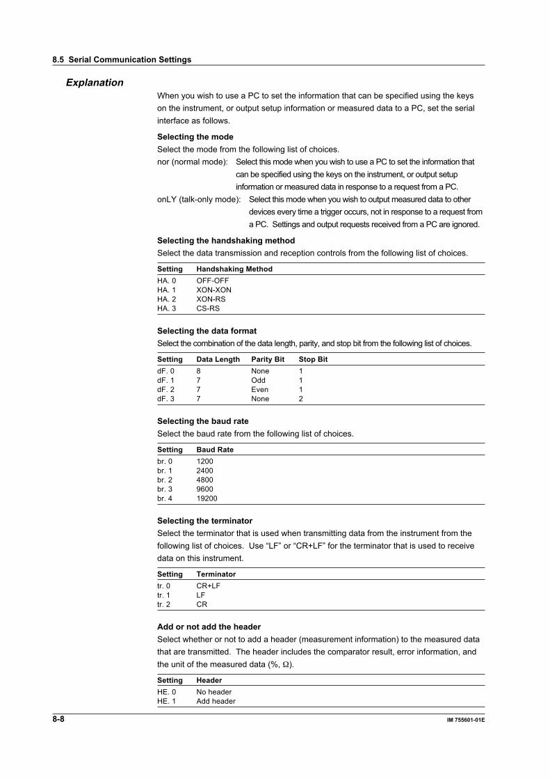
8-8 IM 755601-01E
ExplanationWhen you wish to use a PC to set the information that can be specified using the keyson the instrument, or output setup information or measured data to a PC, set the serialinterface as follows.
Selecting the modeSelect the mode from the following list of choices.nor (normal mode): Select this mode when you wish to use a PC to set the information that
can be specified using the keys on the instrument, or output setupinformation or measured data in response to a request from a PC.
onLY (talk-only mode): Select this mode when you wish to output measured data to otherdevices every time a trigger occurs, not in response to a request froma PC. Settings and output requests received from a PC are ignored.
Selecting the handshaking methodSelect the data transmission and reception controls from the following list of choices.
Setting Handshaking MethodHA. 0 OFF-OFFHA. 1 XON-XONHA. 2 XON-RSHA. 3 CS-RS
Selecting the data formatSelect the combination of the data length, parity, and stop bit from the following list of choices.
Setting Data Length Parity Bit Stop BitdF. 0 8 None 1dF. 1 7 Odd 1dF. 2 7 Even 1dF. 3 7 None 2
Selecting the baud rateSelect the baud rate from the following list of choices.
Setting Baud Ratebr. 0 1200br. 1 2400br. 2 4800br. 3 9600br. 4 19200
Selecting the terminatorSelect the terminator that is used when transmitting data from the instrument from thefollowing list of choices. Use “LF” or “CR+LF” for the terminator that is used to receivedata on this instrument.
Setting Terminatortr. 0 CR+LFtr. 1 LFtr. 2 CR
Add or not add the headerSelect whether or not to add a header (measurement information) to the measured datathat are transmitted. The header includes the comparator result, error information, andthe unit of the measured data (%, Ω).
Setting HeaderHE. 0 No headerHE. 1 Add header
8.5 Serial Communication Settings
Using the G
P-IB Interface
9-1IM 755601-01E
9
Chapter 9 Using the GP-IB Interface
LOCAL keyGP-IB connector
9.1 GP-IB Interface Functions and Specifications
GP-IB Interface FunctionsListener function• All of the information that you set with the panel keys can be set through the GP-IB
interface except turning the power switch ON/OFF and setting the communicationparameters.
• Receives commands from a controller requesting the output of setup information,measured/statistical data, and other information.
• Also receives status report commands.
Talker functionOutputs setup information, measured/statistical data, and other information.
Talk-only functionOutputs measured data without the need to use a controller. This function is usefulwhen you wish to output data to a printer or a listen-only device.
NoteListen-only and controller functions are not available on this instrument.
Switching between Remote and Local ModesWhen switching from local to remote modeReceiving a REN (Remote Enable) message from the controller when the instrument isin the local mode causes the instrument to switch to the remote mode.
• The “REMOTE” indicator turns ON.• All keys other than the LOCAL key are locked.• The settings that existed in the local mode are maintained even when the instrument
switches to the remote mode.
When switching from remote to local modePressing the LOCAL key when the instrument is in the remote mode causes theinstrument to switch to the local mode. However, this act is produces no result if theinstrument has been set to Local Lockout mode (see page 9-4) by the controller.
• “REMOTE” indicator turns OFF.• Key operations are enabled.• The settings that existed in the remote mode are maintained even when the
instrument switches to the local mode.
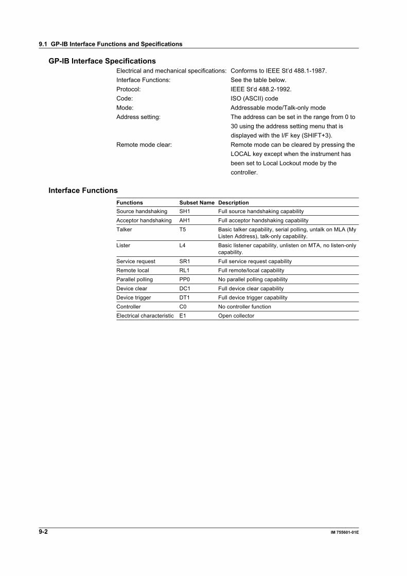
9-2 IM 755601-01E
9.1 GP-IB Interface Functions and Specifications
GP-IB Interface SpecificationsElectrical and mechanical specifications: Conforms to IEEE St’d 488.1-1987.Interface Functions: See the table below.Protocol: IEEE St’d 488.2-1992.Code: ISO (ASCII) codeMode: Addressable mode/Talk-only modeAddress setting: The address can be set in the range from 0 to
30 using the address setting menu that isdisplayed with the I/F key (SHIFT+3).
Remote mode clear: Remote mode can be cleared by pressing theLOCAL key except when the instrument hasbeen set to Local Lockout mode by thecontroller.
Interface FunctionsFunctions Subset Name DescriptionSource handshaking SH1 Full source handshaking capability
Acceptor handshaking AH1 Full acceptor handshaking capabilityTalker T5 Basic talker capability, serial polling, untalk on MLA (My
Listen Address), talk-only capability.
Lister L4 Basic listener capability, unlisten on MTA, no listen-onlycapability.
Service request SR1 Full service request capabilityRemote local RL1 Full remote/local capabilityParallel polling PP0 No parallel polling capability
Device clear DC1 Full device clear capabilityDevice trigger DT1 Full device trigger capability
Controller C0 No controller functionElectrical characteristic E1 Open collector

Using the G
P-IB Interface
9-3IM 755601-01E
9
9.2 Connecting the Interface Cable
GP-IB CableThe GP-IB connector used on this instrument is a 24-pin connector that conforms to theIEEE St’d 488.1-1987. Use a GP-IB cable that conforms to this standard.
Connection ProcedureConnect the cable as shown below.
Precautions to be taken when Connecting the Cable• Firmly tighten the screws on the GP-IB cable connector.• Multiple devices can be connected using multiple cables. However, no more than 15
devices (including the controller) can be connected to a single bus.• When connecting multiple devices, each device must have its own unique address.• Use a cable of length 2 m or less for connecting the devices.• Make sure the total cable length does not exceed 20 m.• When communicating, have at least two-thirds of the devices turned ON.• When connecting multiple devices, connect them in a star or linear configuration (see
the diagram below). Loop and parallel configurations are not allowed.
CAUTION
Make sure to turn OFF the PC and the instrument before connecting ordisconnecting cables. Otherwise, improper operation and/or damage tothe internal circuitry may result.
9-4 IM 755601-01E
9.3 Responses to Interface Messages
Responses to Interface MessagesResponses to a uni-line messageIFC(Interface Clear)Clears the talker and listener functions. Stops output if data are being output.
REN(Remote Enable)Switches between the remote and local modes.
IDY (Identify) is not supported.
Responses to a multi-line message (address command)GET(Group Execute Trigger)Generates a trigger when the trigger mode is set to MANUAL. The operation is thesame as the “*TRG” command.
GTL(Go To Local)Switches to the local mode.
SDC(Selected Device Clear)• Clears the program message (command) being received and the output queue (see
page 10-40).• The *OPC command and *OPC? query that are in execution are disabled.• *WAI and COMMunicate:WAIT commands are immediately terminated.
PPC (Parallel Poll Configure) and TCT(Take Control) are not supported.
Responses to a multi-line message (universal command)LLO(Local Lockout)Disables the Local key on the front panel to prohibit switching to the local mode.
DCL(Device Clear)Same operation as the SDC message.
SPE(Serial Poll Enable)Sets the talker function on all devices on the bus to serial polling mode. The controllerpolls the devices in order.
SPD(Serial Poll Disable)Clears the serial polling mode of the talker function on all devices on the bus.
PPU (Parallel Poll Unconfigure) is not supported.
What is an Interface MessageInterface messages are also referred to as interface commands or bus commands. Theyare commands that are issued by the controller. They are classified as follows.
Uni-line messagesA single control line is used to transmit uni-line messages. The following threemessages are available.IFC (Interface Clear)IDY (Identify)REN (Remote Enable)
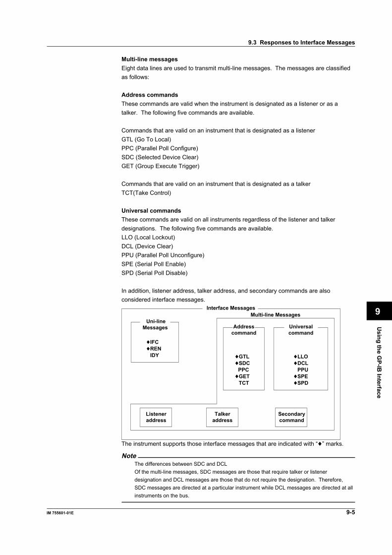
Using the G
P-IB Interface
9-5IM 755601-01E
9
9.3 Responses to Interface Messages
Multi-line messagesEight data lines are used to transmit multi-line messages. The messages are classifiedas follows:
Address commandsThese commands are valid when the instrument is designated as a listener or as atalker. The following five commands are available.
Commands that are valid on an instrument that is designated as a listenerGTL (Go To Local)PPC (Parallel Poll Configure)SDC (Selected Device Clear)GET (Group Execute Trigger)
Commands that are valid on an instrument that is designated as a talkerTCT(Take Control)
Universal commandsThese commands are valid on all instruments regardless of the listener and talkerdesignations. The following five commands are available.LLO (Local Lockout)DCL (Device Clear)PPU (Parallel Poll Unconfigure)SPE (Serial Poll Enable)SPD (Serial Poll Disable)
In addition, listener address, talker address, and secondary commands are alsoconsidered interface messages.
Interface Messages
Uni-lineMessages Address
commandUniversalcommand
♦IFC♦REN
IDY ♦GTL♦SDC
PPC♦GET
TCT
♦LLO♦DCL
PPU♦SPE♦SPD
Listeneraddress
Talkeraddress
Secondarycommand
Multi-line Messages
The instrument supports those interface messages that are indicated with “♦” marks.
NoteThe differences between SDC and DCLOf the multi-line messages, SDC messages are those that require talker or listenerdesignation and DCL messages are those that do not require the designation. Therefore,SDC messages are directed at a particular instrument while DCL messages are directed at allinstruments on the bus.
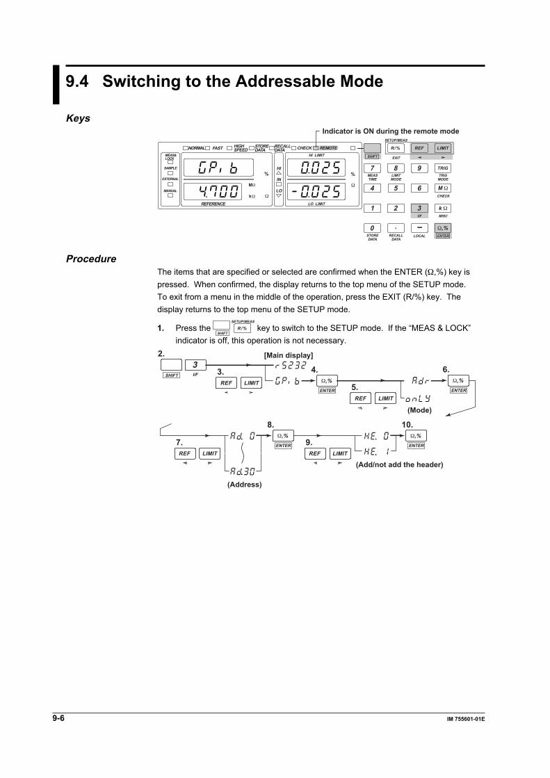
9-6 IM 755601-01E
9.4 Switching to the Addressable Mode
Keys
NORMALMEAS&LOCK
SAMPLE
EXTERNAL
REFERENCE
MANUAL
FAST
HI
HI LIMITEXIT
SETUP/MEAS
CHECK
MISCI/F
MEASTIME
STOREDATA
RECALLDATA
LOCAL ENTER
LIMITMODE
TRIGMODE
SHIFT
R/% REF LIMIT
TRIG7
1
0 .
2 3
54 6
8 9
LO LIMIT
IN
LOMΩ M Ω
k Ω
Ω,%
kΩ Ω
Ω
% %
HIGHSPEED
STOREDATA
RECALLDATA CHECK REMOTE
Indicator is ON during the remote mode
ProcedureThe items that are specified or selected are confirmed when the ENTER (Ω,%) key ispressed. When confirmed, the display returns to the top menu of the SETUP mode.To exit from a menu in the middle of the operation, press the EXIT (R/%) key. Thedisplay returns to the top menu of the SETUP mode.
1. Press the SHIFT
SETUP/MEAS
R/% key to switch to the SETUP mode. If the “MEAS & LOCK”indicator is off, this operation is not necessary.
4.3.
2.
6.
5.
9.
8. 10.
7.
(Mode)
(Address)
(Add/not add the header)
SHIFTREF LIMIT
REF LIMIT
REF LIMIT REF LIMIT
ENTER
Ω,%ENTER
Ω,%
ENTER
Ω,%ENTER
Ω,%
[Main display]
I/F
3
Using the G
P-IB Interface
9-7IM 755601-01E
9
ExplanationSwitching to the addressable modeSelect “Adr” in the mode selection menu.Switch to the addressable mode if you wish to use the controller to set the informationthat you would normally use the panel keys to set or when outputting setup informationor measured data to the controller.
Setting the addressSet the instrument’s address for the addressable mode in the following range:0 to 30Each device that is connected via GP-IB has its own unique address. This address isused for identification. Therefore, make sure to assign a unique address to theinstrument when connecting to a PC.
Add or not add the headerSelect whether or not to add a header (measurement information) to the measured datathat are transmitted.The header includes the comparator result, error information, and the unit of themeasured data (%, Ω).
Setting HeaderHE. 0 No headerHE. 1 Add header
NoteDo not change the address while the controller or other devices are using the GP-IB interface.
9.4 Switching to the Addressable Mode
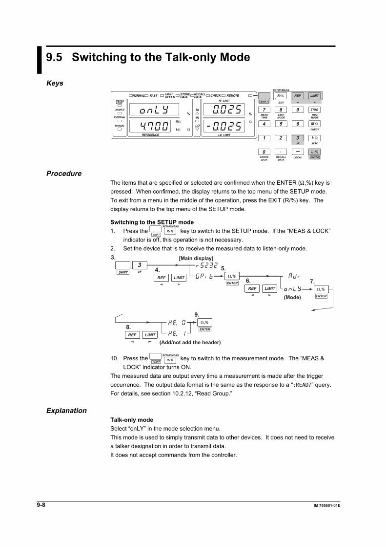
9-8 IM 755601-01E
9.5 Switching to the Talk-only Mode
KeysNORMAL
MEAS&LOCK
SAMPLE
EXTERNAL
REFERENCE
MANUAL
FAST
HI
HI LIMITEXIT
SETUP/MEAS
CHECK
MISCI/F
MEASTIME
STOREDATA
RECALLDATA
LOCAL ENTER
LIMITMODE
TRIGMODE
SHIFT
R/% REF LIMIT
TRIG7
1
0 .
2 3
54 6
8 9
LO LIMIT
IN
LOMΩ M Ω
k Ω
Ω,%
kΩ Ω
Ω
% %
HIGHSPEED
STOREDATA
RECALLDATA CHECK REMOTE
ProcedureThe items that are specified or selected are confirmed when the ENTER (Ω,%) key ispressed. When confirmed, the display returns to the top menu of the SETUP mode.To exit from a menu in the middle of the operation, press the EXIT (R/%) key. Thedisplay returns to the top menu of the SETUP mode.
Switching to the SETUP mode1. Press the
SHIFT
SETUP/MEAS
R/% key to switch to the SETUP mode. If the “MEAS & LOCK”indicator is off, this operation is not necessary.
2. Set the device that is to receive the measured data to listen-only mode.3.
5.4.
7.6.
9.
8.
(Mode)
(Add/not add the header)
SHIFTREF LIMIT
REF LIMIT
REF LIMITENTER
Ω,%
ENTER
Ω,%
ENTER
Ω,%
[Main display]
I/F
3
10. Press the SHIFT
SETUP/MEAS
R/% key to switch to the measurement mode. The “MEAS &LOCK” indicator turns ON.
The measured data are output every time a measurement is made after the triggeroccurrence. The output data format is the same as the response to a “:READ?” query.For details, see section 10.2.12, “Read Group.”
ExplanationTalk-only modeSelect “onLY” in the mode selection menu.This mode is used to simply transmit data to other devices. It does not need to receivea talker designation in order to transmit data.It does not accept commands from the controller.

Com
munication C
omm
ands
10-1IM 755601-01E
10
Chapter 10 Communication Commands
10.1 Before Programming
The communication commands used by this instrument are based on the IEEE488.2 Standard. However, SCPI(Standard Commands for Programmable Instruments) is not supported.
10.1.1 Messages
MessagesMessages are used to exchange information betweenthe controller and the instrument. Messages that aresent from the controller to the instrument are calledprogram messages and messages that are sent backfrom the instrument to the controller are calledresponse messages.If a program message contains a message unit thatrequests a response (a query), the instrument returnsa response message upon receiving the programmessage. One response message is always returnedfor one program message.
Program MessagesThe program message format is shown below.
<PMT>
;
<Program message unit>
<Program message unit>A program message consists of zero or more programmessage units; each unit corresponds to onecommand. The instrument executes the receivedcommands in order.Each program message unit is separated by asemicolon (;). For details regarding the format of theprogram message unit, see the next section.
Example
Unit Unit
:CHECk:MODE BEFore;LEVel 5<PMT>
<PMT>PMT is a program message terminator. The followingthree types of terminators are available.NL (New Line): Same as LF (Line Feed). ASCII
code “0AH”^END: The END message as defined in the
IEEE488.1.(The data byte that is sent with theEND message will be the last data ofthe program message.)
NL^END: NL with an END message attached.(NL is not included in the programmessage.)
Program message unit formatThe program message unit format is shown below.
,
<Program header> <Program data>Space
<Program header>The program header indicates the command type. Fordetails, see page 10-3.
<Program data>If certain conditions are required in executing acommand, program data are added. A space (ASCIIcode “20H”) separates the program data from theheader. If there are multiple sets of program data, theyare separated by commas (,). For details, see page10-5.
Header Data
:CHECk:MODE BEFore<PMT>
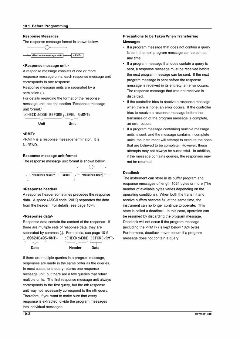
10-2 IM 755601-01E
Response MessagesThe response message format is shown below.
<RMT>
;
<Response message unit>
<Response message unit>A response message consists of one or moreresponse message units; each response message unitcorresponds to one response.Response message units are separated by asemicolon (;).For details regarding the format of the responsemessage unit, see the section “Response messageunit format.”
Unit Unit
:CHECK:MODE BEFORE;LEVEL 5<RMT>
<RMT><RMT> is a response message terminator. It isNL^END.
Response message unit formatThe response message unit format is shown below.
,
<Response header> <Response data>Space
<Response header>A response header sometimes precedes the responsedata. A space (ASCII code “20H”) separates the datafrom the header. For details, see page 10-4.
<Response data>Response data contain the content of the response. Ifthere are multiple sets of response data, they areseparated by commas (,). For details, see page 10-5.
HeaderData Data
1.00824E+05<RMT> :CHECK:MODE BEFORE<RMT>
If there are multiple queries in a program message,responses are made in the same order as the queries.In most cases, one query returns one responsemessage unit, but there are a few queries that returnmultiple units. The first response message unit alwayscorresponds to the first query, but the nth responseunit may not necessarily correspond to the nth query.Therefore, if you want to make sure that everyresponse is extracted, divide the program messagesinto individual messages.
Precautions to be Taken When TransferringMessages• If a program message that does not contain a query
is sent, the next program message can be sent atany time.
• If a program message that does contain a query issent, a response message must be received beforethe next program message can be sent. If the nextprogram message is sent before the responsemessage is received in its entirety, an error occurs.The response message that was not received isdiscarded.
• If the controller tries to receive a response messagewhen there is none, an error occurs. If the controllertries to receive a response message before thetransmission of the program message is complete,an error occurs.
• If a program message containing multiple messageunits is sent, and the message contains incompleteunits, the instrument will attempt to execute the onesthat are believed to be complete. However, theseattempts may not always be successful. In addition,if the message contains queries, the responses maynot be returned.
DeadlockThe instrument can store in its buffer program andresponse messages of length 1024 bytes or more (Thenumber of available bytes varies depending on theoperating conditions). When both the transmit andreceive buffers become full at the same time, theinstrument can no longer continue to operate. Thisstate is called a deadlock. In this case, operation canbe resumed by discarding the program message.Deadlock will not occur if the program message(including the <PMT>) is kept below 1024 bytes.Furthermore, deadlock never occurs if a programmessage does not contain a query.
10.1 Before Programming
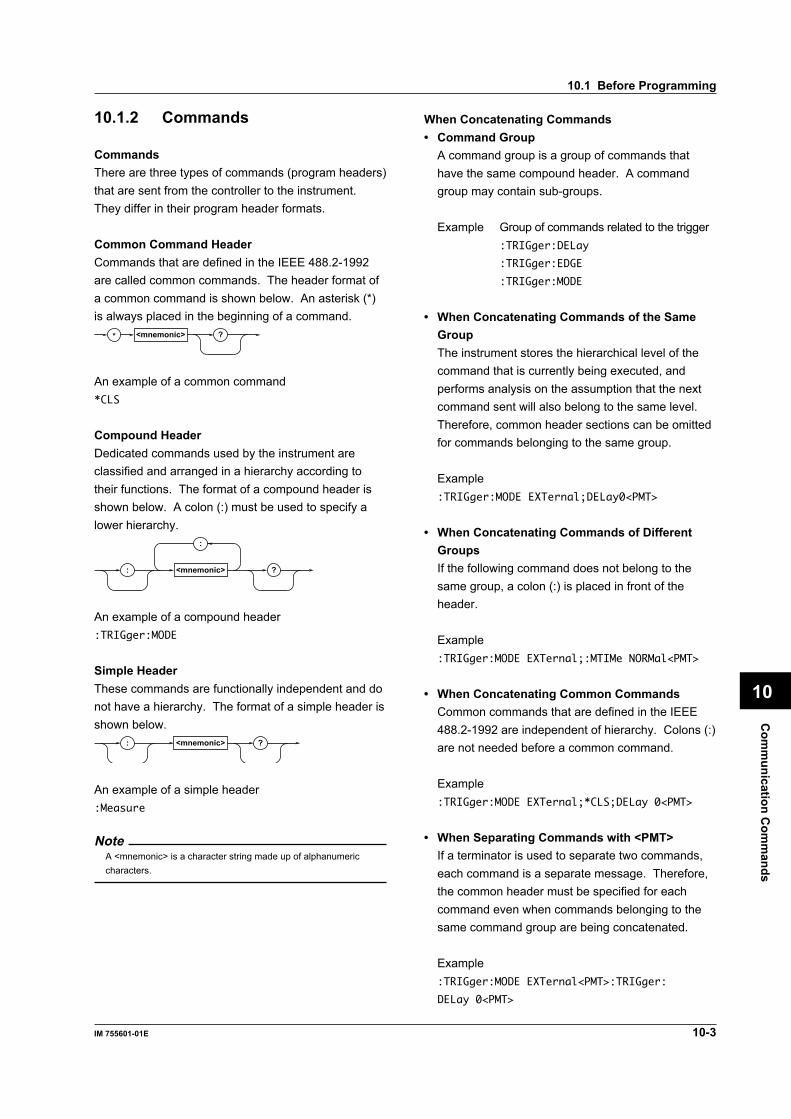
Com
munication C
omm
ands
10-3IM 755601-01E
10
10.1 Before Programming
10.1.2 Commands
CommandsThere are three types of commands (program headers)that are sent from the controller to the instrument.They differ in their program header formats.
Common Command HeaderCommands that are defined in the IEEE 488.2-1992are called common commands. The header format ofa common command is shown below. An asterisk (*)is always placed in the beginning of a command.
* <mnemonic> ?
An example of a common command*CLS
Compound HeaderDedicated commands used by the instrument areclassified and arranged in a hierarchy according totheir functions. The format of a compound header isshown below. A colon (:) must be used to specify alower hierarchy.
:
<mnemonic> ?:
An example of a compound header:TRIGger:MODE
Simple HeaderThese commands are functionally independent and donot have a hierarchy. The format of a simple header isshown below.
<mnemonic> ?:
An example of a simple header:Measure
NoteA <mnemonic> is a character string made up of alphanumericcharacters.
When Concatenating Commands• Command Group
A command group is a group of commands thathave the same compound header. A commandgroup may contain sub-groups.
Example Group of commands related to the trigger:TRIGger:DELay
:TRIGger:EDGE
:TRIGger:MODE
• When Concatenating Commands of the SameGroupThe instrument stores the hierarchical level of thecommand that is currently being executed, andperforms analysis on the assumption that the nextcommand sent will also belong to the same level.Therefore, common header sections can be omittedfor commands belonging to the same group.
Example:TRIGger:MODE EXTernal;DELay0<PMT>
• When Concatenating Commands of DifferentGroupsIf the following command does not belong to thesame group, a colon (:) is placed in front of theheader.
Example:TRIGger:MODE EXTernal;:MTIMe NORMal<PMT>
• When Concatenating Common CommandsCommon commands that are defined in the IEEE488.2-1992 are independent of hierarchy. Colons (:)are not needed before a common command.
Example:TRIGger:MODE EXTernal;*CLS;DELay 0<PMT>
• When Separating Commands with <PMT>If a terminator is used to separate two commands,each command is a separate message. Therefore,the common header must be specified for eachcommand even when commands belonging to thesame command group are being concatenated.
Example:TRIGger:MODE EXTernal<PMT>:TRIGger:
DELay 0<PMT>

10-4 IM 755601-01E
Upper-level QueryAn upper-level query is a query in which a questionmark (?) is appended to the highest level command ofa group. Execution of an upper-level query allows allsettings that can be specified in the group to bereceived at once. Some query groups which arecomprised of more than three hierarchical levels canoutput all the lower level settings.
Example :LIMit?<PMT>→:LIMIT:MODE PCNT;PCNT:
REFERENCE 1.0000E+05;PLIMIT 9.99;
DATA 5.00,—5.00
The response to an upper-level query can betransmitted as a program message back to theinstrument. In this way, the settings that existed whenthe upper-level query was made can be restored.However, some upper-level queries will not returnsetup information that is not currently in use. It isimportant to remember that not all the group’sinformation is necessarily returned as part of aresponse.
Header Interpretation RulesThe instrument interprets the header that is receivedaccording to the following rules.
• Upper-case and lower-case letters of a mnemonicare treated the same.Example ”HEADer” can also be written as “header”
or “Header.”• The lower-case section of the header can be omitted.
Example “HEADer” can also be writen as “HEADE” or“HEAD.”
• The question mark (?) at the end of a headerindicates that it is a query. The question mark (?)cannot be omitted.Example The shortest abbreviation for “HEADer?” is
“HEAD?.”• If the <x> (value) at the end of a mnemonic is
omitted, it is interpreted as a 1.Example If “FILTer<x>” is written as “FILT,” it
means “FILTer1.”• The section enclosed by braces ([]) can be omitted.
Example LIMit[:MODE] can be written as “LIM.”However, the last section enclosed bybraces ([])cannot be omitted in a upper-level query.
Example “LIMit?” and “LIMit:MODE?” are differentqueries.
10.1.3 ResponsesWhen the controller sends a message unit that has aquestion mark (?) in its program header (query), theinstrument returns a response message to the query.A response message is returned in one of the followingtwo forms.
• Response consisting of a header and dataIf the response can be used as a program messagewithout any change, it is returned with a commandheader attached.Example:CHECk:MODE?<PMT>→:CHECK:MODE BEFORE<RMT>
• Response consisting of data onlyIf the response cannot be used as a programmessage unless changes are made to it (query-onlycommand), only the data section is returned.However, there are query-only commands thatreturn responses with the header attached.Example:STATus ERRor?<PMT>→0,”NO ERROR”
When you wish to return a response without aheaderResponses that return both header and data can beset so that only the data section is returned. Use the“COMMunicate:HEADer” command for this task.
Abbreviated formThe response header is normally returned with thelower-case section removed. You can change this sothat the response header is in the full form. Use the“COMMunicate:VERBose” command for this task. Thesections enclosed by braces ([ ]) are also omitted inthe abbreviated form.
10.1 Before Programming
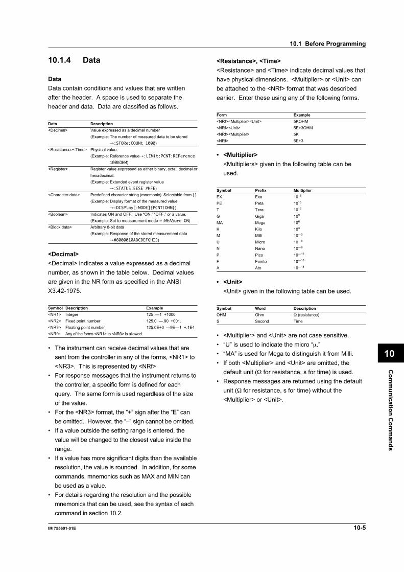
Com
munication C
omm
ands
10-5IM 755601-01E
10
10.1.4 Data
DataData contain conditions and values that are writtenafter the header. A space is used to separate theheader and data. Data are classified as follows.
Data Description<Decimal> Value expressed as a decimal number
(Example: The number of measured data to be stored→:STORe:COUNt 1000)
<Resistance><Time> Physical value(Example: Reference value→:LIMit:PCNT:REFerence
100KOHM)<Register> Register value expressed as either binary, octal, decimal or
hexadecimal.(Example: Extended event register value
→:STATUS:EESE #HFE)<Character data> Predefined character string (mnemonic). Selectable from
(Example: Display format of the measured value→:DISPlay[:MODE]PCNT|OHM)
<Boolean> Indicates ON and OFF. Use “ON,” “OFF,” or a value.(Example: Set to measurement mode→:MEASure ON)
<Block data> Arbitrary 8-bit data(Example: Response of the stored measurement data
→#6000010ABCDEFGHIJ)
<Decimal><Decimal> indicates a value expressed as a decimalnumber, as shown in the table below. Decimal valuesare given in the NR form as specified in the ANSIX3.42-1975.
Symbol Description Example<NR1> Integer 125 —1 +1000<NR2> Fixed point number 125.0 —.90 +001.<NR3> Floating point number 125.0E+0 —9E—1 +.1E4<NRf> Any of the forms <NR1> to <NR3> is allowed.
• The instrument can receive decimal values that aresent from the controller in any of the forms, <NR1> to<NR3>. This is represented by <NRf>
• For response messages that the instrument returns tothe controller, a specific form is defined for eachquery. The same form is used regardless of the sizeof the value.
• For the <NR3> format, the “+” sign after the “E” canbe omitted. However, the “–” sign cannot be omitted.
• If a value outside the setting range is entered, thevalue will be changed to the closest value inside therange.
• If a value has more significant digits than the availableresolution, the value is rounded. In addition, for somecommands, mnemonics such as MAX and MIN canbe used as a value.
• For details regarding the resolution and the possiblemnemonics that can be used, see the syntax of eachcommand in section 10.2.
<Resistance>, <Time><Resistance> and <Time> indicate decimal values thathave physical dimensions. <Multiplier> or <Unit> canbe attached to the <NRf> format that was describedearlier. Enter these using any of the following forms.
Form Example<NRf><Multiplier><Unit> 5KOHM<NRf><Unit> 5E+3OHM<NRf><Multiplier> 5K<NRf> 5E+3
• <Multiplier><Multipliers> given in the following table can beused.
Symbol Prefix MultiplierEX Exa 1018
PE Peta 1015
T Tera 1012
G Giga 109
MA Mega 106
K Kilo 103
M Milli 10—3
U Micro 10—6
N Nano 10—9
P Pico 10—12
F Femto 10—15
A Ato 10—18
• <Unit><Unit> given in the following table can be used.
Symbol Word DescriptionOHM Ohm Ω (resistance)S Second Time
• <Multiplier> and <Unit> are not case sensitive.• “U” is used to indicate the micro “µ.”• “MA” is used for Mega to distinguish it from Milli.• If both <Multiplier> and <Unit> are omitted, the
default unit (Ω for resistance, s for time) is used.• Response messages are returned using the default
unit (Ω for resistance, s for time) without the<Multiplier> or <Unit>.
10.1 Before Programming

10-6 IM 755601-01E
<Register><Register> indicates an integer that can be expressednot only in <Decimal> notation, but also<Hexadecimal>, <Octal>, or <Binary>. <Register> isused when each bit of the value has a particularmeaning. It is expressed in one of the following forms.
Form Example<NRf> 1
#H<Hexadecimal value made up of the digits 0 to 9 and A to F> #H0F
#Q<Octal value made up of the digits 0 to 7> #Q777
#B<Binary value made up of the digits 0 and 1> #B001100
• <Register> is not case sensitive.• Response messages are always returned in the
<NR1> form.
<Character Data><Character Data> are predefined character strings(mnemonic). They are mainly used to indicate options.One of the character strings given in brackets ischosen.The data interpretation is the same as the descriptiongiven in “Header Interpretation Rules” on page 10-4.
Form ExampleNORMal | FAST | HSPeed NORMal
• As with the header, the “COMMunicate:VERBose”command can be used to select whether to returnthe response in the full form or in the abbreviatedform.
• The “COMMunicate:HEADer” setting does not affectthe <character data>.
<Boolean><Boolean> are data that indicate ON or OFF. Theyare expressed in one of the following forms.
Form ExampleON | OFF | <NRf> ON OFF 1 0
When <Boolean> is expressed in the <NRf> form,“OFF” is selected if the rounded integer value is “0,”and ON for all other cases.A response message is always returned with a “1” ifthe value is ON and “0” if the value is OFF.
<Block data><Block data> are data containing arbitrary 8-bit values.<Block data> are only used for response messages onthe instrument. The form is as follows.
Form Example#N<N-digit decimal value><Data byte string> #6000010ABCDEFGHIJ
• #NIndicates that the data are <Block data>. “N” is anASCII character string number (digits) that indicatesthe number of bytes of data that follow.
• <N-digit decimal value>Indicates the number of bytes of data. (Example:000010=10 bytes)
• <Data byte string>Indicates the actual data. (Example: ABCDEFGHIJ)
• Data are comprised of 8-bit values (0 to 255).Therefore, the ASCII code “0AH” which indicates“NL” can also be included in the data. Hence, caremust be taken on the controller side in handling thedata.
10.1 Before Programming
Com
munication C
omm
ands
10-7IM 755601-01E
10
10.1.5 Synchronization with theController
Sequential and Overlap CommandsThere are two types of commands: sequential andoverlap commands.For sequential commands, the execution of thefollowing command does not start until the execution ofthe current command is completed. For overlapcommands, however, the execution of the followingcommand may start before the execution of the currentcommand is completed.Of the commands that are provided by the instrument,the following command is the only overlap command.All other commands are sequential commands.:PRINt:EXECute
Synchronization with Overlap Commands“:PRINt:EXECute” is a command that is used to printdata to an external printer via the Centronics interface.Since printing can take some time depending on theperformance of the external printer or the amount ofdata that is being printed, it is necessary that acommand that aborts the operation, “:PRINt:ABORt,”be executable during the print operation.For example, if the following program is executed, theinstrument will attempt to execute the “:MEAS ON”command before the output to the external printer iscompleted, and, therefore, an execution error occurs.
CMD$ = "PRIN:EXEC" ' Output to an external printerCALL IBWRT(M7556%, CMD$)CMD$ = "MEAS ON" ' Switch to the measurement
modeCALL IBWRT(M7556%, CMD$)
In order to keep the following command from executinguntil the execution of the previously sent overlapcommand is completed, the following commands areused.*WAI
:COMMunicate:OVERlap
*OPC
*OPC?
The use of each command is described in the nextsection.
Using the *WAI command:CMD$ = "COMM:OPSE #H2000" ' ............(1)CALL IBWRT(M7556%, CMD$)CMD$ = "PRIN:EXEC;*WAI" ' ............(2)CALL IBWRT(M7556%, CMD$)CMD$ = "MEAS ON" ' ............(3)CALL IBWRT(M7556%, CMD$):(1) Make the completion of the external printer
operation subject to the *WAI command.(2) Output to the external printer and wait for the
operation to complete.(3) Switch to the measurement mode.
Using the :COMMunicate:OVERlap command:CMD$ = "COMM:OVER 0" ' ............(1)CALL IBWRT(M7556%, CMD$)CMD$ = "PRIN:EXEC" ' ............(2)CALL IBWRT(M7556%, CMD$)CMD$ = "MEAS ON" ' ............(3)CALL IBWRT(M7556%, CMD$):(1) Prohibit the overlap operation of the external
printer operation.(2) Output to the external printer (sequential
operation)(3) Switch to the measurement mode.
Using the *OPC command:CMD$ = "COMM:OPSE #H2000" ' ............(1)CALL IBWRT(M7556%, CMD$)CMD$ = "*ESE 1;*ESR?" ' ............(2)CALL IBWRT(M7556%, CMD$)A$ = SPACE$(8) ' ............(3)CALL IBRD(M7556%, A$)CMD$ = "*SRE 32" ' ............(4)CALL IBWRT(M7556%, CMD$)CMD$ = "PRIN:EXEC;*OPC" ' ............(5)CALL IBWRT(M7556%, CMD$)'(Wait for a service request)CMD$ = "MEAS ON" ' ............(6)CALL IBWRT(M7556%, CMD$):(1) Make the completion of the external printer
operation subject to the *OPC command.(2) Reflect the OPC bit of the standard event
register to the status byte.(3) Read the response to the *ESR? query (clear
the standard event register).(4) Reflect the ESB bit of the status byte register to
the generation of the service request.(5) Output to the external printer and wait for the
OPC bit to be set.(6) Switch to the measurement mode.
10.1 Before Programming

10-8 IM 755601-01E
Using the *OPC? query:CMD$ = "COMM:OPSE #H2000" ' ............(1)CALL IBWRT(M7556%, CMD$)CMD$ = "PRIN:EXEC;*OPC?" ' ............(2)CALL IBWRT(M7556%, CMD$)A$ = SPACE$(8) ' ............(3)CALL IBRD(M7556%, A$)CMD$ = "MEAS ON" ' ............(4)CALL IBWRT(M7556%, CMD$):(1) Make the completion of the external printer
operation subject to the *OPC query.(2) Output to the external printer and wait for the
operation to complete.(3) Read the response to the *OPC? query.(4) Switch to the measurement mode.
Synchronization with Non-Overlap CommandsEven for sequential commands, synchronization issometimes required for non communication-relatedreasons such as a trigger occurrence.For example, if the *TRG command is used to generatea trigger from the controller and then store themeasured data, there is no need to synchronize withthe controller. However, if measured data are to bestored using the external trigger mode, the controllercannot determine when the data store operation iscompleted. Therefore, synchronization with thecontroller is required in order to wait for the storeoperation to complete.
To synchronize with the controller according to thecurrent internal condition of the instrument(“Measurement data store complete,” for example), thefollowing commands that support the extended eventregister are used.:STATus:CONDition?
:STATus:FILTer<x>
:STATus:EESE
:STATus:EESR?
:COMMunicate:WAIT
:COMMunicate:WAIT?
The use of each command is explained in the followingexample in which the measured data are stored orrecalled using the external trigger mode.
Using the external event register:CMD$ = "STOR:COUN 200" ' ............(1)CALL IBWRT(M7556%, CMD$)CMD$ = "STOR ON" ' ............(2)CALL IBWRT(M7556%, CMD$)'
CMD$ = "STAT:FILT10 FALL" ' ............(3)CALL IBWRT(M7556%, CMD$)CMD$ = "STAT:EESE 512" ' ............(4)CALL IBWRT(M7556%, CMD$)CMD$ = "STAT:EESR?" ' ............(5)CALL IBWRT(M7556%, CMD$)N$ = SPACE$(8)CALL IBRD(M7556%, N$)CMD$ = "*SRE 8" ' ............(6)CALL IBWRT(M7556%, CMD$)ON PEN GOSUB STEND ' ............(7)PEN ON ' ............(8)'
CMD$ = "TRIG:MODE EXT" ' ............(9)CALL IBWRT(M7556%, CMD$)CMD$ = "MEAS ON" ' ............(10)CALL IBWRT(M7556%, CMD$)LOOP1: ' ............(11)GOTO LOOP1'
STEND:CMD$ = "MEAS OFF" ' ............(12)CALL IBWRT(M7556%, CMD$)CMD$ = "REC:DATA?" ' ............(13)CALL IBWRT(M7556%, CMD$):(1) Store 200 sets measured data.(2) Enter the store start ready state.(3) Set the external event register on the falling
edge of bit 9 (STR) of the status register.(4) Reflect only bit 9 (STR) of the extended event
register to the status byte.(5) Read the extended event register in order to
clear the register.(6) Reflect the EES bit of the status byte register to
the generation of the service request.(7) Specify the destination to jump to when an
interrupt occurs.(8) Enable the SRQ interrupt.(9) Set the trigger mode to external trigger.(10) Switch to the measurement mode.(11) Wait for the data store operation to complete.(12) Exit from the measurement mode.(13) Query all the measured data that have been
stored.
10.1 Before Programming

Com
munication C
omm
ands
10-9IM 755601-01E
10
Using the :COMMunicate:WAIT command:CMD$ = "STOR:COUN 200" ' ............(1)CALL IBWRT(M7556%, CMD$)CMD$ = "STOR ON" ' ............(2)CALL IBWRT(M7556%, CMD$)'
CMD$ = "STAT:FILT10 FALL" ' ............(3)CALL IBWRT(M7556%, CMD$)CMD$ = "STAT:EESR?" ' ............(4)CALL IBWRT(M7556%, CMD$)N$ = SPACE$(8)CALL IBRD(M7556%, N$)'
CMD$ = "TRIG:MODE EXT" ' ............(5)CALL IBWRT(M7556%, CMD$)CMD$ = "MEAS ON" ' ............(6)CALL IBWRT(M7556%, CMD$)CMD$ = "COMM:WAIT #H0200" ' ............(7)CALL IBWRT(M7556%, CMD$)'
CMD$ = "MEAS OFF" ' ............(8)CALL IBWRT(M7556%, CMD$)CMD$ = "REC:DATA?" ' ............(9)CALL IBWRT(M7556%, CMD$):(1) Store 200 points of measured data.(2) Enter the store start ready state.(3) Set the external event register on the falling
edge of bit 9 (STR) of the status register.(4) Read the extended event register in order to
clear the register.(5) Set the trigger mode to external trigger.(6) Switch to the measurement mode.(7) Wait for bit 9 (STR) of the extended event
register to get set.(8) Exit from the measurement mode.(9) Query all the measured data that have been
stored.
10.1.6 Programming of VariousFunctions
This section describes the commands that are used foreach function and presents examples showing their use.Use this section as a reference when you are actuallyprogramming.The program examples are written in MicrosoftQuickBASIC with AT-GPIB/TNT IEEE488.2 board fromNational Instruments.
Resetting the InstrumentUse one of the following commands.:PANel:INITialize
*RST
Example CMD$ = "*RST"CALL IBWRT(M7556%, CMD$)
Switching between the SETUP and measurementmodesUse the following command.:MEASure
Example 1Switch to the SETUP mode to change theinstrument’s settings when making measurements inthe measurement mode.CMD$ = "MEAS OFF"CALL IBWRT(M7556%, CMD$)
Example 2Start measurements in the measurement mode afterthe settings have been changed.CMD$ = "MEAS ON"CALL IBWRT(M7556%, CMD$)
Selecting the limit mode of the comparatorfunctionUse the following command.:LIMit[:MODE]
Example 1Set the limit mode to deviation (%).CMD$ = "LIM PCNT"CALL IBWRT(M7556%, CMD$)
Example 2Set the limit mode to absolute (R).CMD$ = "LIM OHM"
CALL IBWRT(M7556%, CMD$)
Note• Changing the limit mode clears the preexisting reference value
and limit values.• Select the limit mode before setting the reference value and limit
values.
10.1 Before Programming

10-10 IM 755601-01E
Setting and checking the reference value and limitvaluesWhen the limit mode is set to deviation (%)Use the following command.:LIMit:PCNT:REFerence Set the reference value.:LIMit:PCNT:PLIMit Set the input range
(resolution) of the limit values.:LIMit:PCNT[:DATA] Set the limit values.:LIMit:PCNT? Checking the current
comparator settings.
Example 1Set the reference value to 1kΩ, HI limit value to 5%,and LO limit value to –5%.CMD$ = "LIM:PCNT:REF 1KOHM"
CALL IBWRT(M7556%, CMD$)CMD$ = "LIM:PCNT:PLIM 9.99"CALL IBWRT(M7556%, CMD$)CMD$ = "LIM:PCNT 5,-5"CALL IBWRT(M7556%, CMD$)
Example 2CMD$ = "LIM:PCNT?"CALL IBWRT(M7556%, CMD$)A$ = SPACE$(100)CALL IBRD(M7556%, A$)PRINT A$
NoteChanging the percent limit initializes the limit values. Set thepercent limit before setting the limit values as shown in Example1 above.
When the limit mode is set to absolute (R)Use the following command.:LIMit:OHM[:DATA] Set the limit values.:LIMit:OHM? Check the current comparator
settings.
Example 1Set the HI limit value to 1.05 Ω, LO limit value to0.95 Ω.CMD$ = "LIM:OHM 1.05,0.95"CALL IBWRT(M7556%, CMD$)
Example 2Check the current comparator settings.CMD$ = "LIM:OHM?"CALL IBWRT(M7556%, CMD$)A$ = SPACE$(50)CALL IBRD(M7556%, A$)PRINT A$
Setting the contact checkUse the following command.:CHECk[:MODE]
:CHECk:LEVel
ExampleSet the check level to 5 Ω and perform the contactcheck before the measurement.CMD$ = "CHEC:LEV 5"CALL IBWRT(M7556%, CMD$)CMD$ = "CHEC BEF"CALL IBWRT(M7556%, CMD$)
Switching the displayed unit of the measuredvaluesUse the following command.:DISPlay[:MODE]
ExampleSet the displayed unit of the measured values toabsolute notation (R).CMD$ = "DISP OHM"
CALL IBWRT(M7556%, CMD$)
Setting the measurement timeUse the following command.:MTIMe
ExampleSet the measurement time to Fast.CMD$ = "MTIM FAST"CALL IBWRT(M7556%, CMD$)
Setting the pulse width of the EOM signalUse the following command.:HANDler:EOM
ExampleSet the pulse width of the EOM signal to 10 ms.CMD$ = "HAND:EOM 1E-2"CALL IBWRT(M7556%, CMD$)
Setting the trigger delayUse the following command.:TRIGger:DELay
ExampleSet the trigger delay to 5 ms.CMD$ = "TRIG:DEL 5E-3"CALL IBWRT(M7556%, CMD$)
Setting the trigger edgeUse the following command to set the trigger edge.:TRIGger:EDGE
ExampleSet the trigger edge to the rising edge.CMD$ = "TRIG:EDGE RISE"CALL IBWRT(M7556%, CMD$)
10.1 Before Programming

Com
munication C
omm
ands
10-11IM 755601-01E
10
Setting the triggerTo trigger the measurement from the external controlleror by using the trigger function on the instrument, usethe following commands.:TRIGger:MODE
:MEASure
*TRG
Group Execution Trigger (GET):READ?
Example 1Set the trigger mode to external trigger and triggerthe measurement:CMD$ = "STAT:FILT1 RISE" ' ............(1)CALL IBWRT(M7556%, CMD$)CMD$ = "STAT:EESE 1" ' ............(2)CALL IBWRT(M7556%, CMD$)CMD$ = "STAT:EESR?" ' ............(3)CALL IBWRT(M7556%, CMD$)N$ = SPACE$(8)CALL IBRD(M7556%, N$)CMD$ = "*SRE 8" ' ............(4)CALL IBWRT(M7556%, CMD$)ON PEN GOSUB AVAIL ' ............(5)PEN ON ' ............(6)'CMD$ = "TRIG:MODE EXT" ' ............(7)CALL IBWRT(M7556%, CMD$)CMD$ = "MEAS ON" ' ............(8)CALL IBWRT(M7556%, CMD$)LOOP1: ' ............(9)GOTO LOOP1'AVAIL:CMD$ = "READ?" ' ............(10)CALL IBWRT(M7556%, CMD$)D$ = SPACE$(20)CALL IBRD(M7556%, D$)PRINT D$CALL IBRSP(M7556%, SPR%) ' ............(11)CMD$ = "STAT:EESR?" ' ............(12)CALL IBWRT(M7556%, CMD$)CALL IBRD(M7556%, N$)PEN ON ' ............(13)RETURN:(1) Set the extended event register on the rising
edge of bit 0 (DAV) of the status register.(2) Reflect only bit 0 (DAV) of the extended event
register to the status byte.(3) Read the extended event register in order to
clear the register.(4) Reflect the EES bit of the status byte register to
the generation of the service request.(5) Specify the destination to jump to when an
interrupt occurs.(6) Enable the SRQ interrupt.(7) Set the trigger mode to external trigger.(8) Switch to the measurement mode.(9) Wait for the external trigger signal.(10) Query the measured data.
(11) Clear the SRQ line.(12) Read the extended event register in order to
clear the register.(13) Enable the SRQ interrupt once again.
Example 2Set the trigger to manual trigger and trigger themeasurement:CMD$ = "STAT:FILT1 RISE" ' ............(1)CALL IBWRT(M7556%, CMD$)CMD$ = "STAT:EESE 1" ' ............(2)CALL IBWRT(M7556%, CMD$)CMD$ = "STAT:EESR?" ' ............(3)CALL IBWRT(M7556%, CMD$)N$ = SPACE$(8)CALL IBRD(M7556%, N$)CMD$ = "*SRE 8" ' ............(4)CALL IBWRT(M7556%, CMD$)ON PEN GOSUB AVAIL ' ............(5)PEN ON ' ............(6)'CMD$ = "TRIG:MODE MAN" ' ............(7)CALL IBWRT(M7556%, CMD$)CMD$ = "MEAS ON" ' ............(8)CALL IBWRT(M7556%, CMD$)LOOP1: ' ............(9)V% = 0CALL IBSRE(BD%, V%)GOTO LOOP1'AVAIL:CMD$ = "READ?" ' ............(10)CALL IBWRT(M7556%, CMD$)D$ = SPACE$(20)CALL IBRD(M7556%, D$)PRINT D$CALL IBRSP(M7556%, SPR%) ' ............(11)CMD$ = "STAT:EESR?" ' ............(12)CALL IBWRT(M7556%, CMD$)CALL IBRD(M7556%, N$)PEN ON ' ............(13)RETURN:(1) Set the extended event register on the rising
edge of bit 0 (DAV) of the status register.(2) Reflect only bit 0 (DAV) of the extended event
register to the status byte.(3) Read the extended event register in order to
clear the register.(4) Reflect the EES bit of the status byte register to
the generation of the service request.(5) Specify the destination to jump to when an
interrupt occurs.(6) Enable the SRQ interrupt.(7) Set the trigger mode to manual.(8) Switch to the measurement mode.(9) Wait for the [TRIG] key to be pressed.(10) Query the measured data.(11) Clear the SRQ line.(12) Read the extended event register in order to
clear the register.(13) Enable the SRQ interrupt once again.
10.1 Before Programming

10-12 IM 755601-01E
Example 3Set the trigger mode to internal trigger and triggerthe measurement:CMD$ = "TRIG:MODE INT" ' ............(1)CALL IBWRT(M7556%, CMD$)CMD$ = "MEAS ON" ' ............(2)CALL IBWRT(M7556%, CMD$)LOOP1:CMD$ = "READ?" ' ............(3)CALL IBWRT(M7556%, CMD$)D$ = SPACE$(20)CALL IBRD(M7556%, D$)PRINT D$GOTO LOOP1:(1) Set the trigger mode to internal trigger.(2) Switch to the measurement mode.(3) Query the measured data.
Example 4Use the common command *TRG:CMD$ = "TRIG:MODE MAN" ' ............(1)CALL IBWRT(M7556%, CMD$)CMD$ = "MEAS ON" ' ............(2)CALL IBWRT(M7556%, CMD$)LOOP1:CMD$ = "*TRG" ' ............(3)CALL IBWRT(M7556%, CMD$)CMD$ = "READ?" ' ............(4)CALL IBWRT(M7556%, CMD$)D$ = SPACE$(20)CALL IBRD(M7556%, D$)PRINT D$GOTO LOOP1:(1) Set the trigger mode to manual.(2) Switch to the measurement mode.(3) Generate the trigger.(4) Query the measured data.
NoteQuickBASIC may be interrupted when a GPIB SRQ signaloccurs, and possibly go to a user-specified service routine.To intercept SRQ signal interruptions and to make them availableto user programs, the NI-488.2 for MS-DOS drivers uses theQuickBASIC “ON PEN” statement.
Output Example1.00083E+021.00083E+021.00083E+021.00083E+021.00083E+021.00082E+021.00083E+021.00083E+021.00081E+021.00083E+021.00083E+021.00083E+021.00082E+021.00083E+021.00083E+021.00083E+021.00081E+021.00083E+02
•••
10.1 Before Programming
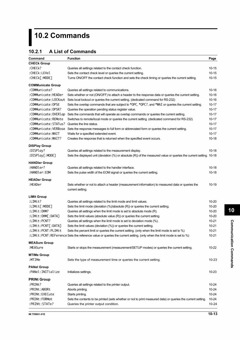
Com
munication C
omm
ands
10-13IM 755601-01E
10
10.2 Commands
10.2.1 A List of CommandsCommand Function PageCHECk Group:CHECk? Queries all settings related to the contact check function. 10-15:CHECk:LEVel Sets the contact check level or queries the current setting. 10-15:CHECk[:MODE] Turns ON/OFF the contact check function and sets the check timing or queries the current setting. 10-15
COMMunicate Group:COMMunicate? Queries all settings related to communications. 10-16:COMMunicate:HEADer Sets whether or not (ON/OFF) to attach a header to the response data or queries the current setting. 10-16:COMMunicate:LOCKout Sets local lockout or queries the current setting. (dedicated command for RS-232) 10-16:COMMunicate:OPSE Sets the overlap commands that are subject to *OPC, *OPC?, and *WAI or queries the current setting. 10-17:COMMunicate:OPSR? Queries the operation pending status register value. 10-17:COMMunicate:OVERlap Sets the commands that will operate as overlap commands or queries the current setting. 10-17:COMMunicate:REMote Switches to remote/local mode or queries the current setting. (dedicated command for RS-232) 10-17:COMMunicate:STATus? Queries the line status. 10-17:COMMunicate:VERBose Sets the response messages to full form or abbreviated form or queries the current setting. 10-17:COMMunicate:WAIT Waits for a specified extended event. 10-17:COMMunicate:WAIT? Creates the response that is returned when the specified event occurs. 10-18
DISPlay Group:DISPlay? Queries all settings related to the measurement display. 10-18:DISPlay[:MODE] Sets the displayed unit (deviation (%) or absolute (R)) of the measured value or queries the current setting. 10-18
HANDler Group:HANDler? Queries all settings related to the handler interface. 10-18:HANDler:EOM Sets the pulse width of the EOM signal or queries the current setting. 10-18
HEADer Group:HEADer Sets whether or not to attach a header (measurement information) to measured data or queries the 10-19
current setting.
LIMit Group:LIMit? Queries all settings related to the limit mode and limit values. 10-20:LIMit[:MODE] Sets the limit mode (deviation (%)/absolute (R)) or queries the current setting. 10-20:LIMit:OHM? Queries all settings when the limit mode is set to absolute mode (R). 10-20:LIMit:OHM[:DATA] Sets the limit values (absolute value (R)) or queries the current setting. 10-20:LIMit:PCNT? Queries all settings when the limit mode is set to deviation mode (%). 10-21:LIMit:PCNT[:DATA] Sets the limit values (deviation (%)) or queries the current setting. 10-21:LIMit:PCNT:PLIMit Sets the percent limit or queries the current setting. (only when the limit mode is set to %) 10-21:LIMit:PCNT:REFerenceSets the reference value or queries the current setting. (only when the limit mode is set to %) 10-21
MEASure Group:MEASure Starts or stops the measurement (measurement/SETUP modes) or queries the current setting. 10-22
MTIMe Group:MTIMe Sets the type of measurement time or queries the current setting. 10-23
PANel Group:PANel:INITialize Initializes settings. 10-23
PRINt Group:PRINt? Queries all settings related to the printer output. 10-24:PRINt:ABORt Aborts printing. 10-24:PRINt:EXECute Starts printing. 10-24:PRINt:FORMat Sets the contents to be printed (sets whether or not to print measured data) or queries the current setting. 10-24:PRINt:STATe? Queries the printer output condition. 10-24

10-14 IM 755601-01E
Command Function PageREAD Group:READ? Queries the measured data. 10-25
RECall Group:RECall? Queries all settings related to the recalling of the measure data. 10-26:RECall:DATA[:ASCii]?Queries the measured data that are stored (ASCII format). 10-26:RECall:DATA:BINary? Queries the measured data that are stored (binary format). 10-27:RECall:RESult? Queries the statistics related to the stored measured data. 10-27:RECall[:STATe] Sets the measured data recall state (ON/OFF) or queries the current setting. 10-28
SELFtest Group:SELFtest:KEY Executes the panel key test. 10-28:SELFtest:LED Executes the LED test. 10-28:SELFtest:HANDler Executes the handler interface output test. 10-28
STATus Group:STATus? Queries all settings related to the communication status. 10-29:STATus:CONDition? Queries the status register. 10-29:STATus:EESE Sets the extended event enable register or queries the current setting. 10-29:STATus:EESR? Queries the extended event register and clears the register. 10-29:STATus:ERRor? Queries the error code and message information (beginning of the error queue). 10-30:STATus:FILTer<x> Sets the transition filter or queries the current setting. 10-30:STATus:QENable Sets whether or not to store messages other than errors in the error queue or queries the current setting. 10-30:STATus:QMESsage Sets whether or not to attach message information to the response to the “:STATus:ERRor?” query or 10-30
queries the current setting.:STATus:SPOLl? Executes serial polling (dedicated command for RS-232). 10-30
STORe Group:STORe? Queries all settings related to the storing of the measured data. 10-30:STORe:COUNt Sets the number of data points to store or queries the current setting. 10-30:STORe:POINts? Queries the number of data points that are stored. 10-31:STORe[:STATe] Sets the measured data store state (ON/OFF) or queries the current setting. 10-31
TRIGger Group:TRIGger? Queries all settings related to the trigger. 10-32:TRIGger:DELay Sets the trigger delay or queries the current setting. 10-32:TRIGger:EDGE Sets the trigger edge or queries the current setting. 10-32:TRIGger:MODE Sets the trigger mode or queries the current setting. 10-32
Common Command Group*CLS Clears the standard event register, extended event register, and error queue. 10-33*ESE Sets the standard event enable register or queries the current setting. 10-33*ESR? Queries the standard event register and clears the register. 10-34*IDN? Queries the instrument model. 10-34*LRN? Queries current group settings. 10-34*OPC Sets an OPC event upon the completion of the specified overlap command. 10-34*OPC? Creates a response upon the completion of the specified overlap command. 10-34*OPT? Queries the installed options. 10-34*PSC Sets whether or not to clear the registers at power up or queries the current setting. 10-34*RST Initializes the settings. 10-34*SRE Sets the service request enable register or queries the current setting. 10-35*STB? Queries the status byte register. 10-35*TRG Executes a manual trigger. 10-35*TST? Performs a self-test and queries the result. 10-35*WAI Holds the subsequent command until the completion of the specified overlap operation. 10-35
10.2 Commands

10-15IM 755601-01E
Com
munication C
omm
ands
10
10.2.2 CHECk(contact CHECk) GroupThe commands in the CHECk(contact CHECk) Group deal with the contact check function.These commands can be used to make the same settings and inquiries as when the CHECK key on the front panel ispressed.
:CHECk : MODE <Space> OFF
BEFore
AFT
MIN
er
MAX
?
LEVel <Space> <Resistance>
?
?
;
:CHECk?Function Queries all settings related to the contact check
function.Syntax :CHECk?
Example When contact check is OFF
:CHECK?→:CHECK:MODE OFF
When contact check is ON (BEFore)
:CHECK?→:CHECK:MODE BEFORE;LEVEL 5
:CHECk:LEVelFunction Sets the contact check level or queries the
current setting.Syntax :CHECk:LEVel <Resistance>|MAX|MIN
:CHECk:LEVel?
<Resistance> = 1 to 30 Ω (Resolution 1 Ω)
MAX = 30 Ω
MIN = 1 Ω
Response <NR1> form
Example :CHECK:LEVEL 5OHM
:CHECK:LEVEL?→:CHECK:LEVEL 5
:CHECk[:MODE]Function Turns ON/OFF the contact check function and
sets the check timing or queries the currentsetting.
Syntax :CHECk[:MODE] OFF|BEFore|AFTer
:CHECk:MODE?
OFF = Contact check: OFF
BEFore = Contact check: ON, check before
measurement
AFTer = Contact check: ON, check after
measurement
Response OFF|BEFore|AFTer
Example :CHECK:MODE OFF
:CHECK:MODE?→:CHECK:MODE OFF
10.2 Commands
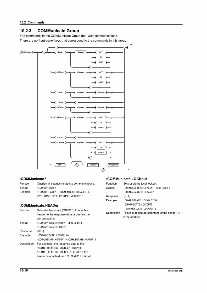
10-16 IM 755601-01E
10.2.3 COMMunicate GroupThe commands in the COMMunicate Group deal with communications.There are no front-panel keys that correspond to the commands in this group.
:COMMunicate : HEADer <Space> OFF
ON
<NRf>
?
LOCKout <Space> OFF
ON
<NRf>
?
OPSE <Space> <Register>
?
OPSR ?
OVERlap <Space> <Register>
?
REMote <Space> OFF
ON
<NRf>
?
STATus ?
VERBose <Space> OFF
ON
<NRf>
?
WAIT ? <Space> <Register>
?
;
:COMMunicate:LOCKoutFunction Sets or clears local lockout.Syntax :COMMunicate:LOCKout <Boolean>
:COMMunicate:LOCKout?
Response 0|1
Example :COMMUNICATE:LOCKOUT ON
:COMMUNICATE:LOCKOUT?
→:COMMUNICATE:LOCKOUT 1
Description This is a dedicated command of the serial (RS-232) interface.
:COMMunicate?Function Queries all settings related to communications.Syntax :COMMunicate?
Example :COMMUNICATE?→:COMMUNICATE:HEADER 1;
OPSE 8192;OVERLAP 8192;VERBOSE 1
:COMMunicate:HEADerFunction Sets whether or not (ON/OFF) to attach a
header to the response data or queries thecurrent setting.
Syntax :COMMunicate:HEADer <Boolean>
:COMMunicate:HEADer?
Response 0|1
Example :COMMUNICATE:HEADER ON
:COMMUNICATE:HEADER?→:COMMUNICATE:HEADER 1
Description For example, the response data to the“:LIMIT:PCNT:REFERENCE?” query is“:LIMIT:PCNT:REFERENCE 1.0E+05” if theheader is attached, and “1.0E+05” if it is not.
10.2 Commands

10-17IM 755601-01E
Com
munication C
omm
ands
10
:COMMunicate:OPSE(Operation Pending Status Enable register)Function Sets the overlap commands that are subject to
*OPC, *OPC?, and *WAI or queries the currentsetting.
Syntax :COMMunicate:OPSE <Register>
:COMMunicate:OPSE?
<Register> = 0 to 65535 (Operation
pending status enable register, see
the description of the :COMMunicate:
OVERlap command)
Response <NR1>
Example :COMMUNICATE:OPSE 65535
:COMMUNICATE:OPSE?→:COMMUNICATE:OPSE
8192
Description In the above example, all bits are set to “1” sothat all overlap commands are subject to *OPC,*OPC?, and *WAI. However, because the bitsthat are fixed to “0” cannot be changed, only bit13 shows a “1” when a query is made.
:COMMunicate:OPSR?(Operation Pending Status Register)Function Queries the operation pending status register
value.Syntax :COMMunicate:OPSR?
Response <NR1> (Operation pending status enable
register, see the description of the
:COMMunicate:OVERlap command)
Example :COMMUNICATE:OPSR?→0
:COMMunicate:OVERlapFunction Sets the commands that will operate as overlap
commands or queries the current setting.Syntax :COMMunicate:OVERlap <Register>
:COMMunicate:OVERlap?
<Register> = 0 to 65535 (Overlap enable
register, see the diagram below)
Response <NR1>
Example :COMMUNICATE:OVERLAP 65535
:COMMUNICATE:OVERLAP?
→:COMMUNICATE:OVERLAP 8192
Description • In the above example, all bits are set to “1”so that all overlap commands are enabled.However, because the bits that are fixed to“0” cannot be changed, only bit 13 shows a“1” when a query is made.
• For the procedures regarding the use of the“:COMMunicate:OVERlap” command forsynchronization, see page 10-7.
• Operation pending status (enable) register/overlap enable register
15 14 13 12 11 10 9 8 7 6 5 4 3 2 1 00 0 PRN 0 0 0 0 0 0 0 0 0 0 0 00
When bit 13 (PRN)=1: External printer outputoperation incomplete
:COMMunicate:REMoteFunction Switches to remote/local mode or queries the
current setting. When the setting is set to ON, itis set to the remote mode.
Syntax :COMMunicate:REMote <Boolean>
:COMMunicate:REMote?
Response 0|1
Example :COMMUNICATE:REMOTE ON
:COMMUNICATE:REMOTE?→:COMMUNICATE:REMOTE 1
Description This is a dedicated command of the serial (RS-232) interface.
:COMMunicate:STATus?Function Queries the line status.Syntax :COMMunicate:STATus?
Response <NR1>
Example :COMMUNICATE:STATUS?→0
Description • The descriptions of the status bits are asfollows.Bit RS-232 GP-IB0 Parity error Unrecoverable
transmission error1 Framing error Always 02 Break character Always 0
detectedOthers Always 0 Always 0
• When a causing event occurs, thecorresponding status bit is set. When thestatus is read, it is cleared.
:COMMunicate:VERBoseFunction Sets the response messages to full form or
abbreviated form or queries the current setting.Syntax :COMMunicate:VERBose <Boolean>
:COMMunicate:VERBose?
Response 0|1
Example :COMMUNICATE:VERBOSE ON
:COMMUNICATE:VERBOSE?
→:COMMUNICATE:VERBOSE 1
Description For example, the response data to the“:TRIGGER:MODE?” query is “:TRIGGER:MODEEXTERNAL” when it is returned in the full formand “:TRIG EXT” when it is returned in theabbreviated form.
:COMMunicate:WAITFunction Waits for a specified extended event.Syntax :COMMunicate:WAIT <Register>
<Register> = 0 to 65535 (Extended event
register, see page 10-39)
Example :COMMUNICATE:WAIT 65535
Description For the procedures regarding the use of the“:COMMunicate:WAIT” command forsynchronization, see page 10-9.
10.2 Commands

10-18 IM 755601-01E
:COMMunicate:WAIT?Function Creates the response that is returned when the
specified event occurs.Syntax :COMMunicate:WAIT? <Register>
<Register> = 0 to 65535 (Extended event
register, see page 10-39)
Response 1 (Fixed)
Example :COMMUNICATE:WAIT? 65535→1
:DISPlay[:MODE]Function Sets the displayed unit (deviation (%) or
absolute (R)) of the measured value or queriesthe current setting.
Syntax :DISPlay[:MODE] PCNT|OHM
:DISPlay:MODE?
PCNT = Deviation (%) display
OHM = Absolute (R) display
Response PCNT|OHM
Example :DISPLAY:MODE PCNT
:DISPLAY:MODE?→:DISPLAY:MODE PCNT
Description When the “:LIMit[:MODE]” is set to OHM, thiscommand cannot be used to specify PCNT.Doing so will result in an error (814).
10.2.4 DISPlay GroupThe commands in the DISPlay Group deal with the measurement display.These commands can be used to make thesame settings and inquiries as when the R/% key on the front panel is pressed.
:DISPlay : MODE <Space> PCNT
OHM
?
?
:DISPlay?Function Queries all settings related to the measurement
display.Syntax :DISPlay?
Example :DISPLAY?→:DISPLAY:MODE PCNT
10.2.5 HANDler GroupThe commands in the HANDler Group deal with the handler interface. These commands can be used to make thesame settings and inquiries as the “Eom” menu accessible through the MISC key on the front panel.
:HANDler : EOM <Space>
MAX
MIN
?
?
<Time>
:HANDler?Function Queries all settings related to the handler
interface output.Syntax :HANDler?
Example :HANDLER?→:HANDLER:EOM 0.0100
:HANDler:EOMFunction Sets the pulse width of the EOM signal or
queries the current setting.Syntax :HANDler:EOM <Time>|MAX|MIN
:HANDler:EOM?
<Time> = 0.1, 5, 10, 15(ms)
MAX = 15ms
MIN = 0.1ms
Response 0.0001|0.0050|0.0100|0.0150 (<NR2>
form)
Example :HANDLER:EOM 10MS
:HANDLER?Æ:HANDLER:EOM 0.0100
10.2 Commands
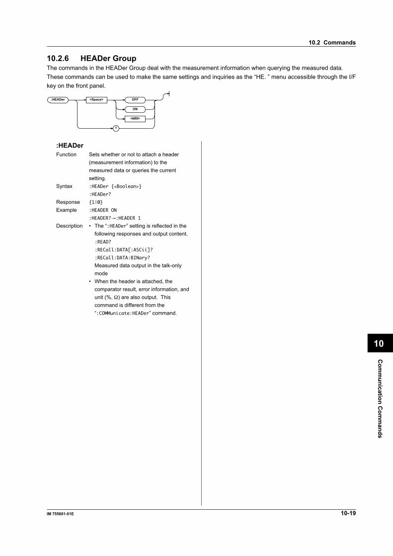
10-19IM 755601-01E
Com
munication C
omm
ands
10
10.2.6 HEADer GroupThe commands in the HEADer Group deal with the measurement information when querying the measured data.These commands can be used to make the same settings and inquiries as the “HE. ” menu accessible through the I/Fkey on the front panel.
:HEADer <Space> OFF
ON
<NRf>
?
:HEADerFunction Sets whether or not to attach a header
(measurement information) to themeasured data or queries the currentsetting.
Syntax :HEADer <Boolean>
:HEADer?
Response 1|0
Example :HEADER ON
:HEADER?→:HEADER 1
Description • The “:HEADer” setting is reflected in thefollowing responses and output content.:READ?
:RECall:DATA[:ASCii]?
:RECall:DATA:BINary?
Measured data output in the talk-onlymode
• When the header is attached, thecomparator result, error information, andunit (%, Ω) are also output. Thiscommand is different from the“:COMMunicate:HEADer” command.
10.2 Commands

10-20 IM 755601-01E
10.2.7 LIMit GroupThe commands in the LIMit Group deal with the limit mode and limit values. These commands can be used to make the samesettings and inquiries as the “PLmt” menu accessible through the LIMIT MODE, REF, LIMIT, and MISC key on the front panel.
:LIMit : MODE <Space> PCNT
OHM
?
PCNT : REFerence <Space>
?
PLIMit <Space> <NRf>
?
DATA <Space> <NRf> , <NRf>
?
?
OHM : DATA <Space> ,
?
?
?
<Resistance>
<Resistance> <Resistance>
;
;
:LIMit?Function Queries all settings related to the limit mode
and limit values.Syntax :LIMit?
Example • When the limit mode is set to deviation mode (%):LIMIT?→:LIMIT:MODE PCNT;PCNT:
REFERENCE 1.0000E+05;PLIMIT 9.99;DATA
5.00,—5.00
• When the limit mode is set to absolute mode (R):LIMIT?→:LIMIT:MODE OHM;OHM:DATA
1.0500E+00,0.9500E+00
:LIMit[:MODE]Function Sets the limit mode or queries the current setting.Syntax :LIMit[:MODE] PCNT|OHM
:LIMit:MODE?
PCNT = Deviation mode (%)
OHM = Absolute mode (R)
Response PCNT|OHM
Example :LIMIT:MODE PCNT
:LIMIT:MODE?→:LIMIT:MODE PCNT
Description When the “:LIMit[:MODE]” setting is changed,the following settings are also automaticallychanged as follows.When changed from OHM to PCNTDisplay unit “:DISPlay[:MODE]” Deviation (%)Limit values “:LIMit:PCNT[:DATA]” HI=0%,
LO=0%Ref. val “:LIMit:PCNT:REFerence” 100.00 kΩWhen changed from PCNT to OHMDisplay unit “:DISPlay[:MODE]” Absolute(R)Limit values “:LIMit:OHM[:DATA]” HI= 0 Ω,
LO= 0 Ω
:LIMit:OHM?Function Queries all settings when the limit mode is set
to absolute mode (R).Syntax :LIMit:OHM?
Example :LIMIT:OHM?→:LIMIT:OHM:DATA 1.0500E+00,
0.9500E+00
:LIMit:OHM[:DATA]Function Sets the limit values (absolute value (R)) or
queries the current setting.Syntax :LIMit:OHM[:DATA] <Resistance (HI)>,
<Resistance (LO)>
:LIMit:OHM:DATA?
<Resistance> = 0.000 Ω to 1.200 Ω
Response <NR3>, <NR3> (Output in the order HI and
LO)
Example :LIMIT:OHM:DATA 1.05OHM,0.95OHM
:LIMIT:OHM:DATA?→:LIMIT:OHM:DATA
1.0500E+00, 0.9500E+00
Description • The HI value must be greater than the LOvalue. Otherwise, an error (815) occurs.
• When the “:LIMit[:MODE]” is set to PCNT,the “:LIMit:OHM[:DATA]” setting cannot bechanged or queried. Doing so will result inan error (812).
10.2 Commands

10-21IM 755601-01E
Com
munication C
omm
ands
10
:LIMit:PCNT?Function Queries all settings when the limit mode is set
to deviation mode (%).Syntax :LIMit:PCNT?
Example :LIMIT:PCNT?→:LIMIT:PCNT:
REFERENCE 1.0000E+05;PLIMIT 9.99;DATA
5.00, —5.00
:LIMit:PCNT[:DATA]Function Sets the limit values (deviation (%)) or queries
the current setting.Syntax :LIMit:PCNT[:DATA] <NRf(HI)>[,<NRf(LO)>]
:LIMit:PCNT:DATA?
When the “:LIMit:PCNT:PLIMit” is set to9.99<NRf> = —9.99 to 9.99% (Resolution 0.01%)
When the “:LIMit:PCNT:PLIMit” is set to99.9<NRf> = —99.9 to 99.9% (Resolution 0.1%)
Response <NR2>, <NR2> (Outputs in the order HI
and LO.)
Example :LIMIT:PCNT:DATA —5,5
:LIMIT:PCNT:DATA?→:LIMIT:PCNT:DATA
5.00,—5.00
Description • The range and resolution of the limit values varydepending on the “:LIMit:PCNT:PLIMit” setting.
• If the LO parameter is omitted, the valueequal to (0 – HI) is set to LO.
• If HI is less than LO, an error (815) occurs.• When the “:LIMit[:MODE]” is set to OHM,
the “:LIMit:PCNT[:DATA]” setting cannot bechanged or queried. Doing so will result inan error (813).
:LIMit:PCNT:PLIMitFunction Sets the percent limit when the limit mode is set
to deviation (%) or queries the current setting.Syntax :LIMit:PCNT:PLIMit <NRf>
:LIMit:PCNT:PLIMit?
<NRf> = 9.99 or 99.9
Response 9.99|99.90(<NR2> form)
Example :LIMIT:PCNT:PLIMit 9.99
:LIMIT:PCNT:PLIMIT?→:LIMIT:PCNT:PLIMIT
9.99
Description • When the “:LIMit:PCNT:PLIMit” is changed,the following settings are also automaticallychanged.When the percent limit is changed from9.99 to 99.9Limit values HI = 0.0%, LO = 0.0%(:LIMit:PCNT[:DATA])When the percent limit is changed from99.9 to 9.99Limit values HI = 0.00%, LO = 0.00%(:LIMit:PCNT[:DATA])
• When the “:LIMit[:MODE]” is set to OHM,the “:LIMit:PCNT:PLIMit” setting cannot bechanged or queried. Doing so will result inan error (813).
:LIMit:PCNT:REFerenceFunction Sets the reference value when the limit mode is
set to deviation (%) or queries the currentsetting.
Syntax :LIMit:PCNT:REFerence <Resistance>
:LIMit:PCNT:REFerence?
<Resistance> = 0.0000 Ω to 120.00 MΩ
Response <NR3> form
Example :LIMIT:PCNT:REFERENCE 100KOHM
:LIMIT:PCNT:REFERENCE?→:LIMIT:PCNT:
REFERENCE 1.0000E+05
Description • The measurement range is determined bythe “:LIMit:PCNT:REFerence” setting.
• When the “:LIMit[:MODE]” is set to OHM,the “:LIMit:PCNT:REFerence” setting cannotbe changed or queried. Doing so will resultin an error (813).
10.2 Commands
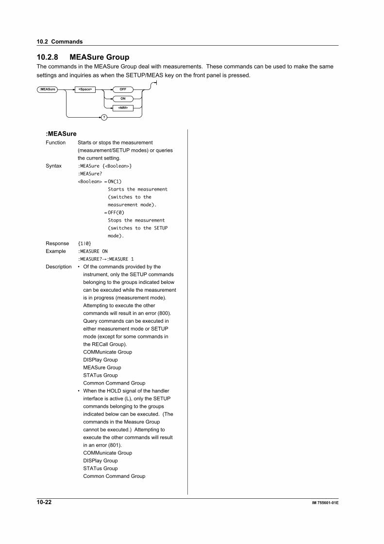
10-22 IM 755601-01E
10.2.8 MEASure GroupThe commands in the MEASure Group deal with measurements. These commands can be used to make the samesettings and inquiries as when the SETUP/MEAS key on the front panel is pressed.
:MEASure <Space> OFF
ON
<NRf>
?
:MEASureFunction Starts or stops the measurement
(measurement/SETUP modes) or queriesthe current setting.
Syntax :MEASure <Boolean>
:MEASure?
<Boolean> = ON(1)
Starts the measurement
(switches to the
measurement mode).
= OFF(0)
Stops the measurement
(switches to the SETUP
mode).
Response 1|0
Example :MEASURE ON
:MEASURE?→:MEASURE 1
Description • Of the commands provided by theinstrument, only the SETUP commandsbelonging to the groups indicated belowcan be executed while the measurementis in progress (measurement mode).Attempting to execute the othercommands will result in an error (800).Query commands can be executed ineither measurement mode or SETUPmode (except for some commands inthe RECall Group).COMMunicate GroupDISPlay GroupMEASure GroupSTATus GroupCommon Command Group
• When the HOLD signal of the handlerinterface is active (L), only the SETUPcommands belonging to the groupsindicated below can be executed. (Thecommands in the Measure Groupcannot be executed.) Attempting toexecute the other commands will resultin an error (801).COMMunicate GroupDISPlay GroupSTATus GroupCommon Command Group
10.2 Commands
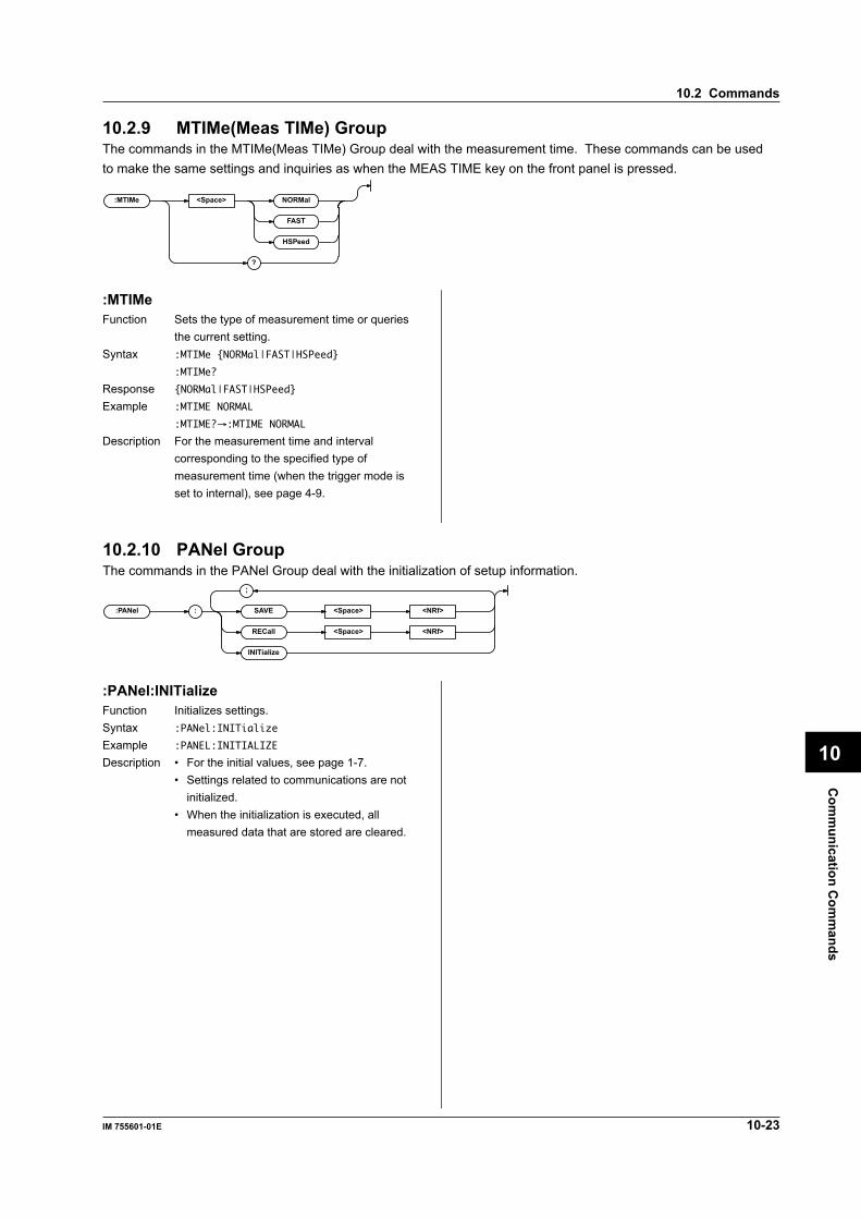
10-23IM 755601-01E
Com
munication C
omm
ands
10
10.2.9 MTIMe(Meas TIMe) GroupThe commands in the MTIMe(Meas TIMe) Group deal with the measurement time. These commands can be usedto make the same settings and inquiries as when the MEAS TIME key on the front panel is pressed.
:MTIMe <Space> NORMal
FAST
HSPeed
?
10.2.10 PANel GroupThe commands in the PANel Group deal with the initialization of setup information.
:PANel : SAVE <Space> <NRf>
RECall <Space> <NRf>
INITializ e
;
:MTIMeFunction Sets the type of measurement time or queries
the current setting.Syntax :MTIMe NORMal|FAST|HSPeed
:MTIMe?
Response NORMal|FAST|HSPeed
Example :MTIME NORMAL
:MTIME?→:MTIME NORMAL
Description For the measurement time and intervalcorresponding to the specified type ofmeasurement time (when the trigger mode isset to internal), see page 4-9.
:PANel:INITializeFunction Initializes settings.Syntax :PANel:INITialize
Example :PANEL:INITIALIZE
Description • For the initial values, see page 1-7.• Settings related to communications are not
initialized.• When the initialization is executed, all
measured data that are stored are cleared.
10.2 Commands

10-24 IM 755601-01E
10.2.11 PRINt Group (Option)The commands in the PRINt Group deal with the print functions available via the Centronics interface.These commands can be used to make the same settings and inquiries as the “Prin” or “dAtA” menu accessiblethrough the MISC key on the front panel.
:PRINt : STAT e ?
EXECute
ABORt
FORMat <Space> OFF_A4
ON_A4
OFF_RP
ON_RP
?
?
;
:PRINt:FORMatFunction Sets the contents to be printed (sets whether or
not to print measured data) or queries thecurrent setting.
Syntax :PRINt:FORMat OFF_A4|ON_A4|OFF_RP|ON_RP
:PRINt:FORMat?
OFF_RP = Prints the statistics to a paper
size (roll paper) on which 40
characters can be printed
horizontally. Measured data are
not printed.
ON_RP = Prints the statistics as well as
the measured data to a paper
size (roll paper) on which 40
characters can be printed
horizontally.
OFF_A4 = Prints the statistics to an A4
size paper. Measured data are
not printed.
ON_A4 = Prints the statistics as well as
the measured data to an A4 size
paper.
Response OFF_A4|ON_A4|OFF_RP|ON_RP
Example :PRINT:FORMAT OFF_A4
:PRINT:FORMAT?→:PRINT:FORMAT OFF_A4
:PRINt:STATe?Function Queries the printer output condition.Syntax :PRINt:STATe?
Response BUSY|IDLE
BUSY = Printer busy
IDLE = Printer ready
Example :PRINT:STATE?→IDLE
:PRINt?Function Queries all settings related to the printer output.Syntax :PRINt?
Example :PRINT?→:PRINT:FORMAT OFF_RP
:PRINt:ABORtFunction Aborts printing.Syntax :PRINt:ABORt
Example :PRINT:ABORT
:PRINt:EXECuteFunction Starts printing. This is an overlap commandSyntax :PRINt:EXECute
Example :PRINT:EXECUTE
Description • Outputs the measured data that are stored inthe internal memory and the statistics of thedata to an external printer.
• Printing fails with an error (830) if there areno measured data stored in the memory.
10.2 Commands

10-25IM 755601-01E
Com
munication C
omm
ands
10
10.2.12 READ GroupThe commands in the READ Group deal with the querying of the measured data. There are no front-panel keys thatcorrespond to the commands in this group.
:READ ?
:READ?Function Queries the measured data.Syntax :READ?
Response <Measurement information>, <Data>• <Measurement information> = <NR1> form,
register value in decimal notation (See thefigure below)(The values inside the parentheses () arethose which exist when the measurement isdisplayed in Ω.)0: No data3 (131): Normal data (Comparator result: IN)5 (133): Normal data (Comparator result: HI)9 (137): Normal data (Comparator result: LO)21: Overrange (Comparator result:
fixed to HI)37: Contact check error (Comparator
result: fixed to HI)69: Abnormalities detected in the test
current (Comparator result: fixed toHI)
• <Data> = <NR3> formWhen the measurement display is set to %[–]*.*****E+02 Mantissa: 5.5 digits maximum,Exponent:02 (fixed)When the measurement display is set to Ω[–]*.*****E+** Mantissa: 5.5 digits maximum,Exponent: depends on the measurement range.When there are no data (Display “----”)9.91E+37 (NAN:Not A Number)When overrange (Display “–oL–”)When contact check error (Display “–n.C–”)When abnormalities are detected in the testcurrent (Display “–c.F–”)9.9E+37 (INFinity:+∞)
Example This is an example in which the measurementinformation is ON (“:HEADer ON”). When themeasurement information is OFF,<Measurement information> and "," are notoutput.• During % display: READ?→3,0.00987E+02
(Comparator result:IN) (0.987%)• During % display: READ?→9,—0.05012E+02
(Comparator result:LO) (—5.012%)• During Ω display: READ?→133,1.06135E+07
(Comparator result:HI) (10.6135 MΩ)• When there are no data: READ?→0,9.91E+37
• When the value is over the range:READ?→21,9.9E+37
• When a contact check error occurs:READ?→37,9.9E+37
• When abnormalities are detected in the testcurrent : READ?→69,9.9E+37
Description • The instrument stores the measured resultsto the measurement data buffer every time ameasurement completes. “:READ?” is aquery used to inquire about the contents ofthe measurement data buffer. The buffer iscleared when a query is made.
• When the “:TRIGger:MODE” is set toEXTernal or MANual, there are cases inwhich the measurement data buffer is empty,because the next measurement is not yetcomplete. The response in this casecontains no data (<Measurementinformation> is “0,” <Data> is “9.91E+37”).
• When the measurement is stopped and theinstrument switches to the SETUP mode(“:MEASure OFF”), the measurement databuffer is cleared.
• You can determine whether or not themeasured result is stored in the measurementdata buffer by checking whether or not bit 0(DAV) of the status register is set to “1.”
• The <Data> condition and the comparatorresults are included in the <Measurementinformation>. The bit assignments of theinformation are as follows:
7 6 5 4 3 2 1 0OHM C.F OVR LO HI IN DAVN.C
bit0 (DAV): Set to “1” when the measured dataare stored in the output buffer.
bit1 (IN): Set to “1” when the comparatorresult is “IN.”
bit2 (HI): Set to “1” when the comparatorresult is “HI.”
bit3 (LO): Set to “1” when the comparatorresult is “LO.”
bit4 (OVR): Set to “1” when the measuredvalue is over the range. (Display“–oL–”)
bit5 (N.C): Set to “1” when a contact checkerror occurs. (Display “–n.C–”)
bit6 (C.F): Set to “1” when abnormalities aredetected in the test current.(Display “–C.F–”)
bit7 (OHM): Set to “1” when the measured dataare correct absolute (R) data.
10.2 Commands
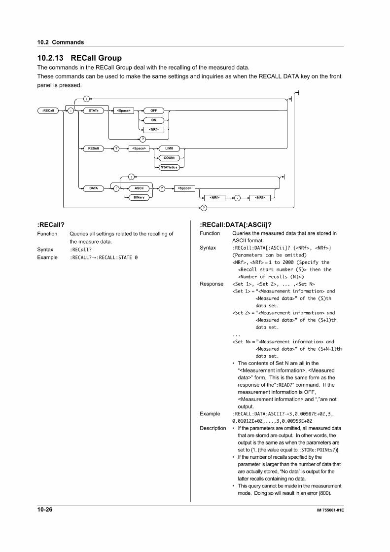
10-26 IM 755601-01E
10.2.13 RECall GroupThe commands in the RECall Group deal with the recalling of the measured data.These commands can be used to make the same settings and inquiries as when the RECALL DATA key on the frontpanel is pressed.
:RECall : STAT e <Space> OFF
ON
<NRf>
?
RESult ? <Space> LIMit
COUNt
STATistics
DATA : ASCii ? <Space>
<NRf> , <NRf>BINar y
?
;
;
:RECall?Function Queries all settings related to the recalling of
the measure data.Syntax :RECall?
Example :RECALL?→:RECALL:STATE 0
:RECall:DATA[:ASCii]?Function Queries the measured data that are stored in
ASCII format.Syntax :RECall:DATA[:ASCii]? <NRf>, <NRf>
(Parameters can be omitted)
<NRf>, <NRf> = 1 to 2000 (Specify the
<Recall start number (S)> then the
<Number of recalls (N)>)
Response <Set 1>, <Set 2>, ... ,<Set N>
<Set 1> = “<Measurement information> and
<Measured data>” of the (S)th
data set.
<Set 2> = “<Measurement information> and
<Measured data>” of the (S+1)th
data set.
...
<Set N> = ”<Measurement information> and
<Measured data>” of the (S+N—1)th
data set.
• The contents of Set N are all in the“<Measurement information>, <Measureddata>” form. This is the same form as theresponse of the“:READ?” command. If themeasurement information is OFF,<Measurement information> and “,”are notoutput.
Example :RECALL:DATA:ASCII?→3,0.00987E+02,3,
0.01012E+02,...,3,0.00953E+02
Description • If the parameters are omitted, all measured datathat are stored are output. In other words, theoutput is the same as when the parameters areset to 1, (the value equal to :STORe:POINts?).
• If the number of recalls specified by theparameter is larger than the number of data thatare actually stored, “No data” is output for thelatter recalls containing no data.
• This query cannot be made in the measurementmode. Doing so will result in an error (800).
10.2 Commands

10-27IM 755601-01E
Com
munication C
omm
ands
10
:RECall:DATA:BINary?Function Queries the measured data that are stored in
binary format.Syntax :RECall:DATA:BINary? <NRf>, <NRf>
(Parameters can be omitted)
<NRf>, <NRf> = 1 to 2000 (Specify the
<Recall start number (S)> then the
<Number of recalls (N)>)
Response #6<Number of bytes><Data>
# = Character indicating <Block data> (1
byte)
6 = Number of digits needed to express
the <Number of bytes> (1 byte)
<Number of bytes> = Six-digit decimal
indicating the length of <Measured
data> (6 bytes)
<Data> = <Set 1><Set 2>...<Set N>
<Set 1> = “<Measurement information>
<Measured data>” of the (S)th
data set.
<Set 2> = “<Measurement information>
<Measured data>” of the (S+1)th
data set.
...
<Set N> = “<Measurement information>
<Measured data>” of the (S+N—1)th
data set.
• The contents of Set N are all in the“<Measurement information><Measured data>” form. The contents of the<Measurement information> and <Measureddata> are the same as the response to the“:READ?” command, but the form is differentas indicated below.<Measurement information> = 1-byte
register value (Not output when the
measurement information is turned
OFF)
<Measured data> = 4-byte IEEE single-
precision floating point decimal
data
The real number RN that is expressed in theIEEE single-precision floating point decimalformat is provided by the following equation.SEEEEEEE EMMMMMMM MMMMMMMM MMMMMMMM
RN = (—1)^S * (2^(E—127)) * (1+M/(2^23))
S: Sign (0 or 1)
E: Exponential value (0 to 254)
M: Mantissa value (23-bit binary)
Example :RECALL:DATA:BINARY?→#6010000<Data>
Description • The parameter contents and the data setsequence are the same as the“:RECall:DATA[:ASCii]?” command.
• This query cannot be made in themeasurement mode. Doing so will result inan error (800).
:RECall:RESult?Function Queries the statistics related to the measured
data that are stored.Syntax :RECall:RESult? LIMit|COUNt|STATistics
(Parameters can be omitted)
LIMit = Outputs the limit values that
existed when data were stored.
COUNt = Outputs the result that has been
classified by the various
conditions of the stored data.
STATistics = Outputs the statistics of
the stored data.
Response • In the case “:RECall:RESult? LIMit”<Limit–Mode>, <REFerence>, <HI–Limit>,<LO–Limit><Limit–Mode> = PCNT|OHM: Limit mode<REFerence> = <NR3> form: Deviation (%)
reference, “9.91E+37” whenthe limit mode is OHM.
<High–Limit> = <NR3> form: Limit value (HI)<Low–Limit> = <NR3> form: Limit value (LO)
• In the case “:RECall:RESult? COUNt”<IN>, <HI>, <LO>, <NC><IN> = <NR1> form: Number of comparator
results that were IN, “0” when thecomparator is turned OFF.
<HI> = <NR1> form: Number of comparatorresults that were HI, “0” when thecomparator is turned OFF.
<LO> = <NR1> form: Number of comparatorresults that were LO, “0” when thecomparator is turned OFF.
<NC> = <NR1> form: Number of contactcheck errors or occurrences in whichabnormalities are detected in the testcurrent.
• In the case “:RECall:RESult? STATistics” or“:RECall:RESult?”<Valid>, <Invalid>, <Maximum>, <Minimum>,<Extent>, <Average>, <1–Sigma>, <3–Sigma><Valid> = <NR1> form: Number of valid samples<Invalid> = <NR1> form: Number of invalid
samples (Number of data pointsresulting in <NC> or overrage)
<Maximum> = <NR3> form: Maximum<Minimum> = <NR3> form: Minimum<Extent> = <NR3> form: Range (Maximum –
Minimum)<Average> = <NR3> form: Average<1–Sigma> = <NR3> form: Standard
deviation σ<3–Sigma> = <NR3> form: 3σ
10.2 Commands

10-28 IM 755601-01E
Example :RECALL:RESULT? LIMIT
→PCNT,1.0000E+05,5.00, —5.00
:RECALL:RESULT? COUNT→1971,14,8,7
:RECALL:RESULT? STATISTICS→1990,10,
0.06378E+02,—0.05249E+02,0.11627E+02,
0.010057E+02,0.0462821E+02,0.1388463E+02
Description • If the parameter is omitted, it is equivalent tospecifying STATistics.
• A query cannot be made if there are nomeasured data that are stored. Doing so willresult in an error (830).
• This query cannot be made in themeasurement mode. Doing so will result inan error (800).
• Statistical computation is performed on thecommunication output data (5.5 digits).
:RECall[:STATe]Function Sets the measured data recall state (ON/OFF)
or queries the current setting.Syntax :RECall[:STATe] <Boolean>
:RECall:STATe?
Response 1|0
Example :RECALL:STATE ON
:RECALL:STATE?→:RECALL:STATE 1
Description • Executing the “:RECall[:STATe] ON” commandsets the instrument in a recall start ready state.The actual recall operation is not executed at thispoint. Measured data are recalled from thememory every time a trigger occurs after theinstrument is switched to the measurementmode using the “:MEASure ON” command.
• When the last data point is recalled, the“:RECall[:STATe]” is automatically turned OFF.Executing the “:RECall[:STATe] OFF”command will forcibly terminate the recalloperation.
• When there are no measured data stored in thememory, “:RECall[:STATe]” cannot be turnedON. This will result in an error (830).
• If the “:STORe[:STATe]” is turned ON,“:RECall[:STATe]” cannot be turned ON.Attempting to do so will result in an error (832).
10.2.14 SELFtest GroupThe commands in the SELFtest Group deal with the self test function. These commands can be used to make thesame settings and inquiries as the “tESt” menu accessible through the MISC key on the front panel.
:SELFtest : KEY
LED
HANDler
;
10.2 Commands
:SELFtest:KEYFunction Executes the panel key test.Syntax :SELFtest:KEY
Example :SELFTEST:KEY
Description For the test description, see page 11-6.
:SELFtest:LEDFunction Executes the LED test.Syntax :SELFtest:LED
Example :SELFTEST:LED
Description For the test description, see page 11-6.
:SELFtest:HANDlerFunction Executes the handler interface output test.Syntax :SELFtest:HANDler
Example :SELFTEST:HANDLER
Description For the test description, see page 11-6.
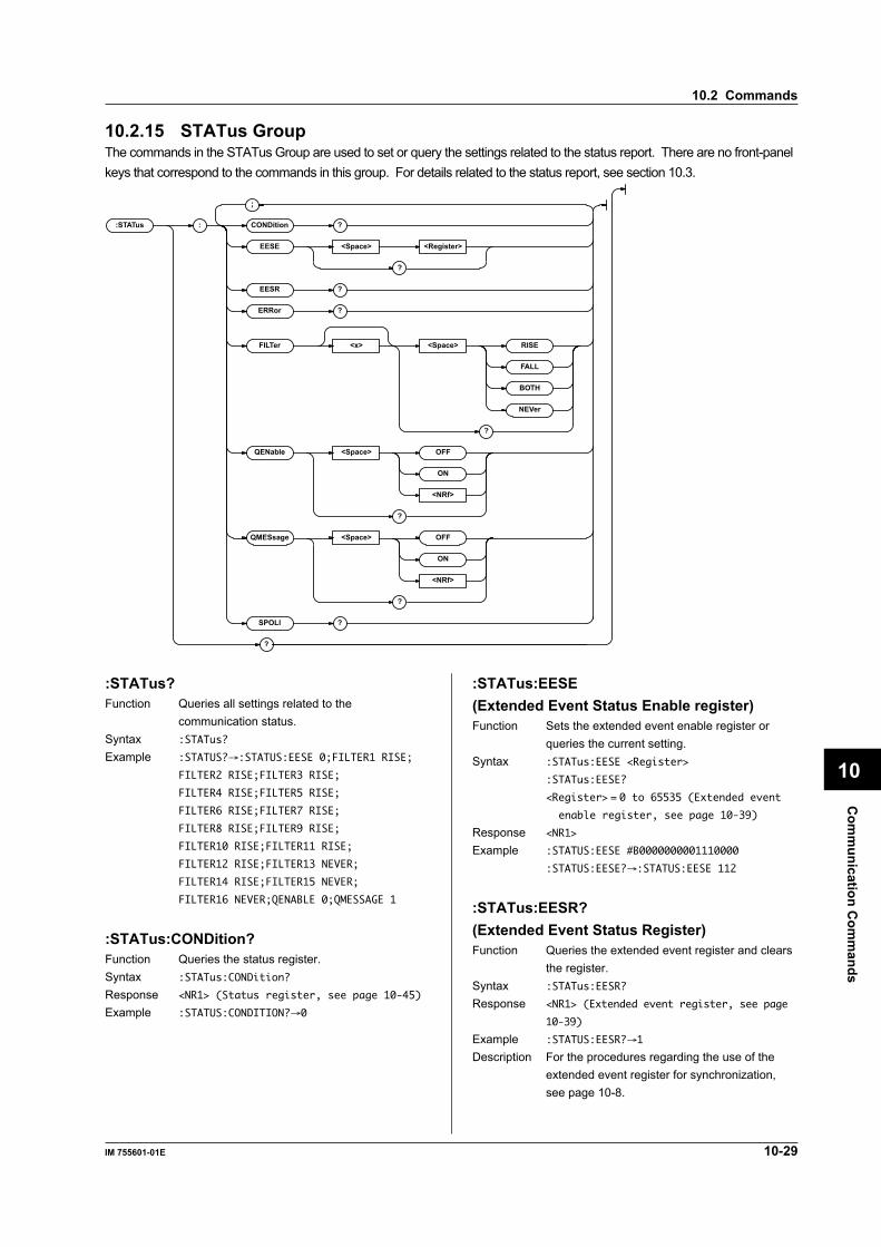
10-29IM 755601-01E
Com
munication C
omm
ands
10
10.2.15 STATus GroupThe commands in the STATus Group are used to set or query the settings related to the status report. There are no front-panelkeys that correspond to the commands in this group. For details related to the status report, see section 10.3.
:STATus : CONDition ?
EESE <Space> <Register>
?
EESR ?
ERRor ?
FILTer <x> <Space> RISE
FALL
BOTH
NEVer
?
QENable <Space> OFF
ON
<NRf>
?
QMESsage <Space> OFF
ON
<NRf>
?
SPOLl ?
?
;
:STATus?Function Queries all settings related to the
communication status.Syntax :STATus?
Example :STATUS?→:STATUS:EESE 0;FILTER1 RISE;
FILTER2 RISE;FILTER3 RISE;
FILTER4 RISE;FILTER5 RISE;
FILTER6 RISE;FILTER7 RISE;
FILTER8 RISE;FILTER9 RISE;
FILTER10 RISE;FILTER11 RISE;
FILTER12 RISE;FILTER13 NEVER;
FILTER14 RISE;FILTER15 NEVER;
FILTER16 NEVER;QENABLE 0;QMESSAGE 1
:STATus:CONDition?Function Queries the status register.Syntax :STATus:CONDition?
Response <NR1> (Status register, see page 10-45)
Example :STATUS:CONDITION?→0
:STATus:EESE(Extended Event Status Enable register)Function Sets the extended event enable register or
queries the current setting.Syntax :STATus:EESE <Register>
:STATus:EESE?
<Register> = 0 to 65535 (Extended event
enable register, see page 10-39)
Response <NR1>
Example :STATUS:EESE #B0000000001110000
:STATUS:EESE?→:STATUS:EESE 112
:STATus:EESR?(Extended Event Status Register)Function Queries the extended event register and clears
the register.Syntax :STATus:EESR?
Response <NR1> (Extended event register, see page
10-39)
Example :STATUS:EESR?→1
Description For the procedures regarding the use of theextended event register for synchronization,see page 10-8.
10.2 Commands
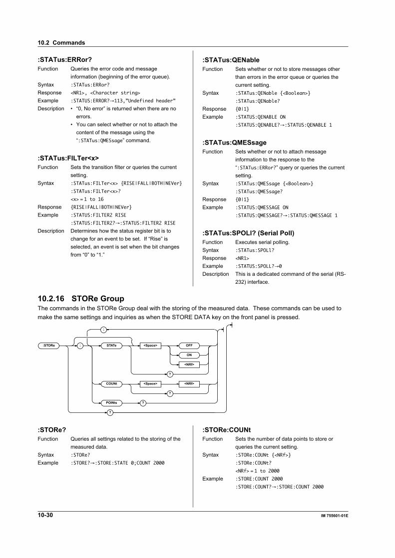
10-30 IM 755601-01E
:STATus:ERRor?Function Queries the error code and message
information (beginning of the error queue).Syntax :STATus:ERRor?
Response <NR1>, <Character string>
Example :STATUS:ERROR?→113,”Undefined header”
Description • “0, No error” is returned when there are noerrors.
• You can select whether or not to attach thecontent of the message using the“:STATus:QMESsage” command.
:STATus:FILTer<x>Function Sets the transition filter or queries the current
setting.Syntax :STATus:FILTer<x> RISE|FALL|BOTH|NEVer
:STATus:FILTer<x>?
<x> = 1 to 16
Response RISE|FALL|BOTH|NEVer
Example :STATUS:FILTER2 RISE
:STATUS:FILTER2?→:STATUS:FILTER2 RISE
Description Determines how the status register bit is tochange for an event to be set. If “Rise” isselected, an event is set when the bit changesfrom “0” to “1.”
:STATus:QENableFunction Sets whether or not to store messages other
than errors in the error queue or queries thecurrent setting.
Syntax :STATus:QENable <Boolean>
:STATus:QENable?
Response 0|1
Example :STATUS:QENABLE ON
:STATUS:QENABLE?→:STATUS:QENABLE 1
:STATus:QMESsageFunction Sets whether or not to attach message
information to the response to the“:STATus:ERRor?” query or queries the currentsetting.
Syntax :STATus:QMESsage <Boolean>
:STATus:QMESsage?
Response 0|1
Example :STATUS:QMESSAGE ON
:STATUS:QMESSAGE?→:STATUS:QMESSAGE 1
:STATus:SPOLl? (Serial Poll)Function Executes serial polling.Syntax :STATus:SPOLl?
Response <NR1>
Example :STATUS:SPOLL?→0
Description This is a dedicated command of the serial (RS-232) interface.
10.2.16 STORe GroupThe commands in the STORe Group deal with the storing of the measured data. These commands can be used tomake the same settings and inquiries as when the STORE DATA key on the front panel is pressed.
:STORe : STAT e <Space> OFF
ON
<NRf>
?
COUNt <Space> <NRf>
?
POINts ?
?
;
:STORe?Function Queries all settings related to the storing of the
measured data.Syntax :STORe?
Example :STORE?→:STORE:STATE 0;COUNT 2000
:STORe:COUNtFunction Sets the number of data points to store or
queries the current setting.Syntax :STORe:COUNt <NRf>
:STORe:COUNt?
<NRf> = 1 to 2000
Example :STORE:COUNT 2000
:STORE:COUNT?→:STORE:COUNT 2000
10.2 Commands
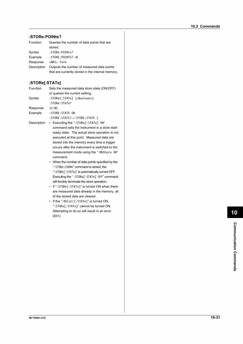
10-31IM 755601-01E
Com
munication C
omm
ands
10
:STORe:POINts?Function Queries the number of data points that are
stored.Syntax :STORe:POINts?
Example :STORE:POINTS?→0
Response <NR1> form
Description Outputs the number of measured data pointsthat are currently stored in the internal memory.
:STORe[:STATe]Function Sets the measured data store state (ON/OFF)
or queries the current setting.Syntax :STORe[:STATe] <Boolean>
:STORe:STATe?
Response 1|0
Example :STORE:STATE ON
:STORE:STATE?→:STORE:STATE 1
Description • Executing the “:STORe[:STATe] ON”command sets the instrument in a store startready state. The actual store operation is notexecuted at this point. Measured data arestored into the memory every time a triggeroccurs after the instrument is switched to themeasurement mode using the “:MEASure ON”command.
• When the number of data points specified by the“:STORe:COUNt” command is stored, the“:STORe[:STATe]” is automatically turned OFF.Executing the “ :STORe[:STATe] OFF” commandwill forcibly terminate the store operation.
• If “:STORe[:STATe]” is turned ON when thereare measured data already in the memory, allof the stored data are cleared.
• If the “:RECall[:STATe]” is turned ON,“:STORe[:STATe]” cannot be turned ON.Attempting to do so will result in an error(831).
10.2 Commands
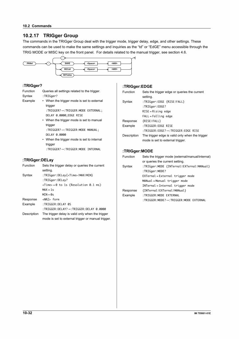
10-32 IM 755601-01E
10.2.17 TRIGger GroupThe commands in the TRIGger Group deal with the trigger mode, trigger delay, edge, and other settings. Thesecommands can be used to make the same settings and inquiries as the “td” or “EdGE” menu accessible through theTRIG MODE or MISC key on the front panel. For details related to the manual trigger, see section 4.6.
:PANel : SAVE <Space> <NRf>
RECall <Space> <NRf>
INITializ e
;
:TRIGger?Function Queries all settings related to the trigger.Syntax :TRIGger?
Example • When the trigger mode is set to externaltrigger:TRIGGER?→:TRIGGER:MODE EXTERNAL;
DELAY 0.0000;EDGE RISE
• When the trigger mode is set to manualtrigger:TRIGGER?→:TRIGGER:MODE MANUAL;
DELAY 0.0000
• When the trigger mode is set to internaltrigger:TRIGGER?→:TRIGGER:MODE INTERNAL
:TRIGger:DELayFunction Sets the trigger delay or queries the current
setting.Syntax :TRIGger:DELay<Time>|MAX|MIN
:TRIGger:DELay?
<Time> = 0 to 1s (Resolution 0.1 ms)
MAX = 1s
MIN = 0s
Response <NR2> form
Example :TRIGGER:DELAY 0S
:TRIGGER:DELAY?→:TRIGGER:DELAY 0.0000
Description The trigger delay is valid only when the triggermode is set to external trigger or manual trigger.
:TRIGger:EDGEFunction Sets the trigger edge or queries the current
setting.Syntax :TRIGger:EDGE RISE|FALL
:TRIGger:EDGE?
RISE = Rising edge
FALL = Falling edge
Response RISE|FALL
Example :TRIGGER:EDGE RISE
:TRIGGER:EDGE?→:TRIGGER:EDGE RISE
Description The trigger edge is valid only when the triggermode is set to external trigger.
:TRIGger:MODEFunction Sets the trigger mode (external/manual/internal)
or queries the current setting.Syntax :TRIGger:MODE INTernal|EXTernal|MANual
:TRIGger:MODE?
EXTernal = External trigger mode
MANual = Manual trigger mode
INTernal = Internal trigger mode
Response INTernal|EXTernal|MANual
Example :TRIGGER:MODE EXTERNAL
:TRIGGER:MODE?→:TRIGGER:MODE EXTERNAL
10.2 Commands

10-33IM 755601-01E
Com
munication C
omm
ands
10
10.2.18 Common Command GroupThe commands in the common group are defined in the IEEE 488.2-1992 and are independent of the instrument’sfunctions. There are no front-panel keys that correspond to the commands in this group.
*CLS
*ESE <Space> <NRf>
?
*ESR ?
*IDN ?
*LRN ?
*OPC
*OPC ?
*OPT ?
*PSC <Space> <NRf>
?
*RST
*SRE <Space> <NRf>
?
*STB ?
*TRG
*TST ?
*WAI
;
*CLS (CLear Status)Function Clears the standard event register, extended
event register, and error queue.Syntax *CLS
Example *CLS
Description • If the “*CLS” command is appendedimmediately after the program messageterminator, the output queue is also cleared.
• For details regarding registers and queues,see section 10.3.
*ESE (standard Event Status Enable register)Function Sets the standard event enable register or
queries the current setting.Syntax *ESE <NRf>
*ESE?
<NRf> = 0 to 255
Example *ESE 251
*ESE?→251
Description • <NRf> is the sum of the bits expressed as adecimal number.
• In the above example, the standard eventenable register is set to “11111011.” In otherwords, bit 2 of the standard event register isdisabled so that even if a query error occurs,bit 5 (ESB) of the status byte register is notset to “1.”
• The default value is “*ESE 0” (all bitsdisabled).
• An “*ESE?” query will not clear the standardevent enable register.
• For details regarding the standard eventenable register, see page 10-38.
10.2 Commands

10-34 IM 755601-01E
*ESR? (standard Event Status Register)Function Queries the standard event register and clears
the register.Syntax *ESR?
Example *ESR?→32
Description • The sum of the bits is returned as a decimalvalue.
• This query can be used to check the type ofevent that occurred when a SRQ is inprogress.
• In the above example, the returned value of“32” indicates that the standard event registeris set to “00100000.” In other words, the SRQoccurred due to a “command syntax error.”
• An “*ESR?” query will clear the standard eventregister.
• For details regarding the standard eventenable register, see page 10-38.
*IDN? (IDeNtify)Function Queries the instrument model.Syntax *IDN?
Example *IDN?→YOKOGAWA,755601,0,F1.01
Description A reply is returned in the following form:<Manufacturer>, <Model>, <Serial number(always 0)>, <Firmware version>.
*LRN? (LeaRN)Function Queries current settings of the following groups:
LIMit, DISPlay, RANGe, MTIMe, TRIGger,CHECk, HANDler
Syntax *LRN?
Example *LRN?→:LIMIT:MODE PCNT;PCNT:
REFERENCE 1.0000E+05;PLIMIT 9.99;
DATA 0.00, 0.00;:DISPLAY:MODE PCNT;:
RANGE 1.0E+05;MTIME NORMAL;TRIGGER:
MODE EXTERNAL;DELAY 0.0000;EDGE RISE;:
CHECK:MODE BEFORE;LEVEL 30;:HANDLER:
EOM 0.0100
*OPC (OPeration Complete)Function Sets bit 0 of the standard event register (OPC)
upon the completion of the specified overlapcommand.
Syntax *OPC
Example *OPC
Description • For the procedures regarding the use of the“*OPC” command for synchronization, seepage 10-7.
• An overlap command is specified using the“:COMMunicate:OPSE” command.
• Proper operation is not guaranteed unlessthe “*OPC” command is placed at the end ofthe message.
*OPC? (OPeration Complete)Function Returns the ASCII code “1” upon the
completion of the specified overlap command.Syntax *OPC?
Example *OPC?→1
Description • For the procedures regarding the use of the“*OPC?” command for synchronization, seepage 10-8.
• An overlap command is specified using the“:COMMunicate:OPSE” command.
• Proper operation is not guaranteed unlessthe “*OPC?” command is placed at the end ofthe message.
*OPT? (OPTion)Function Queries the installed options.Syntax *OPT?
Example *OPT?→GP-IB,PRINTER
Description • Returns the existence of the <GP-IBinterface> and <Centronics interface>.
• An ASCII code “0” is returned, if neither ofthe options is installed.
• The “*OPT?” command must be the last queryin a program message. Otherwise, an errorresults.
*PSC (Power-on Status Clear)Function Sets whether or not to clear the following
registers at power up or queries the currentsetting. The registers are cleared when a non-zero value is specified.Standard event enable registerExtended event enable registerTransition filter
Syntax *PSC <NRf>
*PSC?
<NRf> = 0 (Does not clear the register),
a non-zero value (Clears the register)
Example *PSC 1
*PSC?→1
Description For details regarding registers, see section10.3.
*RST (ReSeT)Function Initializes the settings.Syntax *RST
Example *RST
Description • For the initial values, see page 1-7. Setupinformation except for that related tocommunications is initialized.
• Previously sent *OPC and *OPC? commandsare also cleared.
10.2 Commands

10-35IM 755601-01E
Com
munication C
omm
ands
10
*SRE (Service Request Enable register)Function Sets the service request enable register or
queries the current setting.Syntax *SRE <NRf>
*SRE?
<NRf> = 0 to 255
Example *SRE 239
*SRE?→175 (Because the setting for bit
6 (MSS) is ignored)
Description • <NRf> is the sum of the bits expressed as adecimal number.
• In the above example, the service requestenable register is set to”11101111.” In otherwords, bit 4 of the service request enableregister is disabled so that bit 6 (MSS) of thestatus byte register is not set to “1” evenwhen the output queue is not empty.
• However, bit 6 (MSS) of the status byteregister is the MSS bit, and is thereforeignored.
• The default value is “*SRE 0” (all bitsdisabled).
• A “*SRE?” query will not clear the servicerequest enable register.
• For details regarding the service requestenable register, see pages 10-36 and 10-37.
*STB? (STatus Byte)Function Queries the status byte register.Syntax *STB?
Example *STB→4
Description • The sum of the bits is returned as a decimalvalue.
• Because the register is read without serialpolling, bit 6 is the MSS bit, not RQS.
• In the above example, the returned value of“4” indicates that the status byte register isset to “00000100.” In other words, “the errorqueue is not empty” (an error occurred).
• A “*STB?” query will not clear the status byteregister.
• For details regarding the status byte registersee page 10-37.
*TRG (TRiGger)Function Executes a manual trigger and makes one
measurement.Syntax *TRG
Example *TRG
Description • This command is valid only when the“:TRIGger:MODE” is set to MANual.
• The interface message GET (Group ExecuteTrigger) also achieves the same operation.
• For details regarding measurements usingthe “*TRG” command, see page 10-12.
*TST? (TeST)Function Performs a self test and queries the result.Syntax *TST?
Example *TST?→0
Description • Performs an internal self-test, and returns thesum of the error codes as a test result. If noerrors occur, a “0” is returned. This self-test isthe same test that is performed at power-up.Test Item Error Code
• Check the minimum voltage level 1of the backup battery
• Check the checksum of the 2backup RAM (Settings otherthan those related tocommunications)
• Check the checksum of the 4backup RAM(Communication settings)
• Check the checksum of the 8backup RAM (SETUP file)
• Calibration data(EEPROM) 16
*WAI (WAIt)Function Holds the subsequent command until the
completion of the specified overlap operation.Syntax *WAI
Example *WAI
Description • For the procedures regarding the use of the“*WAI” command for synchronization, seepage 10-7.
• An overlap command is specified using the“:COMMunicate:OPSE” command.
10.2 Commands

10-36 IM 755601-01E
10.3 Status Report
10.3.1 About the Status Report
15 14 13 12 11 10 9 8 7 6 5 4 3 2 1 0
15 14 13 12 11 10 9 8 7 6 5 4 3 2 1 0
15 14 13 12 11 10 9 8 7 6 5 4 3 2 1 0
Condition filter
Transition filter
Extended event register&
15 14 13 12 11 10 9 8 7 6 5 4 3 2 1 0 Extended event enable register
&&
&&
&&
&&
&&
&&
&&
&
7 6 5 4 3 2 1 0 Standard event register&
&&
&&
&&
&
7 6 5 4 3 2 1 0 Standard event enable register
OR
OR
7 6 ESBMAVEES EAV 1 0 Status byte registerMSS
RQS
Outputqueue
Errorqueue
Servicerequestoccurrence
&&
&&
&&
&
7 6 5 4 3 2 1 0 Service request enable register
OR
<Status Report>The figure shows the status report that is read by serial polling. This status report is an extended version of the status report defined in IEEE 488.2-1992.

Com
munication C
omm
ands
10-37IM 755601-01E
10
Summary of the Registers and QueuesName Function Write ReadStatus byte — Serial polling
(RQS), *STB?(MSS)Service request Status byte mask *SRE *SRE?
enable registerStandard event Changes in device — *ESR?
register statusStandard event Standard event *ESE *ESE?
enable register register maskExtended event Changes in device — STATus:EESR?
register statusExtended event Extended event STATus:EESE STATus:EESE?
enable register register maskStatus register Current device status — STATus:CONDition?
Transition filter Conditions that STATus:FILTer<x> STATus:FILTer<x>?
change the extendedevent register
Output queue Stores a response All query commandsmessage to a query
Error queue Stores the error No. — STATus:ERRor?
and message
Registers and Queues that Affect the Status ByteRegisters that affect the contents of the status byte areshown below.Standard event register: Sets bit 5 (ESB) of the status byte to “1” or “0.”Output queue: Sets bit 4 (MAV) of the status byte to “1” or “0.”Extended event register: Sets bit 3 (EES) of the status byte to “1” or “0.”Error queue: Sets bit 2 (EAV) of the status byte to “1” or “0.”
Enable RegistersRegisters that are used to mask a bit so that the bit willnot affect the status byte, even if it is set to 1, areshown below.Status byte: Mask the bits using the service request enable register.Standard event register: Mask the bits using the standard event enable register.Extended event register: Mask the bits using the extended event enable register.
Reading and Writing to the RegistersFor example, the *ESE command is used to set the bitsin the standard event enable register to 1’s or 0’s. The*ESE? command is used to query whether the bits in thestandard event enable register are 1’s or 0’s. Fordetails regarding these commands, see section 10.2.
10.3.2 Status ByteStatus byte
7 6 ESBMAVEES EAV 1 0RQS
MSS
Bits 0, 1, and 7Not used (always 0)
Bit 2 EAV (Error Available)Set to “1” when the error queue is not empty. In otherwords, this bit is set to “1” when an error occurs. Seepage 10-40.
Bit 3 EES (Extend Event Summary Bit)Set to “1” when the logical product of the extendedevent register and the corresponding event register isnot “0.” In other words, this bit is set to “1” when anevent occurs inside the instrument. See page 10-39.
Bit 4 MAV (Message Available)Set to “1” when the output queue is not empty. Inother words, this bit is set to “1” when there are data tobe transmitted. See page 10-40.
Bit 5 ESB (Event Summary Bit)Set to “1” when the logical product of the standardevent register and the corresponding event register isnot “0.” In other words, this bit is set to “1” when anevent occurs inside the instrument. See page 10-39.
Bit 6 RQS (Request Service)/MSS (Master StatusSummary)Set to “1” when the logical AND of the status byteexcluding Bit 6 and the service request enable registeris not “0.” In other words, this bit is set to “1” when theinstrument is requesting service from the controller.RQS is set to “1” when the MSS bit changes from “0”to “1,” and cleared when the MSS bit changes to “0.”
Bit MaskingIf you wish to mask a certain bit of the status byte sothat it does not cause a SRQ, set the corresponding bitof the service request enable register to “0.”For example, to mask bit 2 (EAV) so that service is notrequested when an error occurs, set bit 2 of the servicerequest enable register to “0.” This is done using the*SRE command. The *SRE? request command can beused to query the service request enable register tocheck whether each bit is set to “1” or “0.” For detailsregarding the *SRE command, see section 10.2.
10.3 Status Report

10-38 IM 755601-01E
Status Byte OperationA service request is issued when bit 6 of the statusbyte becomes a “1.” Bit 6 is set to “1” when any of theother bits becomes a “1” (when the corresponding bitof the service request enable register is also set to “1”).For example, if an event occurs and the logical AND ofthe standard event register and the correspondingenable register becomes a “1”, then bit 5 (ESB) is setto “1.” At this point, if bit 5 of the service requestenable register is “1,” then bit 6 (MSS) is set to “1”causing the instrument to request service from thecontroller.In addition, you can also check what type of eventoccurred by reading the contents of the status byte.
Reading the Status ByteThe following two methods are available to read thecontents of the status byte.• Query using the *STB? commandA *STB? query causes bit 6 to be a MSS bit.Therefore, the MSS bit is read. No bits in the statusbyte are cleared after reading the status byte.
• Serial pollingSerial polling causes bit 6 to be a RQS bit. Therefore,the RQS bit is read. After reading the status byte, onlythe RQS bit is cleared. You cannot read the MSS bitwhen serial polling is used.
Clearing the Status ByteThere are no methods available that can forcibly clearall the bits of the status byte. The bits that are clearedfor each operation are shown below.• When a query is made using the *STB? commandNone of the bits are cleared.
• When serial polling is executedOnly the RQS bit is cleared.
• When a *CLS command is receivedReceiving the *CLS command will not clear the statusbyte itself, but the contents of the standard eventregister that affect the status byte. As a result, thecorresponding bit of the status byte is cleared. Sincethe *CLS command does not clear the output queue,bit 4 (MAV) of the status byte is unaffected. However,if the *CLS command is received immediately after theprogram message terminator, the output queue is alsocleared.
10.3.3 Standard event registerStandard event register
URQ6
PON7 5 4 3 2 1 0
CMEEXE DDEQYERQCOPC
Bit 7 PON (Power ON)Set to “1” when the instrument is turned ON.
Bit 6 URQ (User Request)Not used (always 0)
Bit 5 CME(Command Syntax Error)Set to “1” when there is an error in the command syntax.Example: Misspelling of a command name, “9” exists
in octal data
Bit 4 EXE (Execution Error)Set to “1” when the command syntax is correct, but thecommand cannot be executed in the current state ofthe instrument.Example: Parameter outside the range, Tried to print
while measurement is in progress.
Bit 3 DDE (Device Dependent Error)Set to “1” when a command cannot be executed forinternal reasons other than a command syntax errorand command execution error.
Bit 2 QYE (Query Error)Set to “1” when a query command is transmitted, butthe error queue is empty or the data are lost.Example: No response data, Output queue overflowed
and data were lost.
Bit 1 RQC (Request Control)Not used (always 0)
Bit 0 OPC (Operation Complete)Set to “1” when the operation specified by the *OPCcommand (see section 10.2) has been completed.
Bit MaskingIf you wish to mask a certain bit of the standard eventregister so that it does not cause bit 5 of the status byte tochange, set the corresponding bit of the standard eventenable register to “0.” For example, to mask bit 2 (QYE) sothat the ESB bit is not set to “1” when a query error occurs,set bit 2 of the standard event enable register to “0.” This isdone using the *ESE command. The *ESE? requestcommand can be used to query the standard event enableregister to check whether each bit is set to “1” or “0.” Fordetails regarding the *ESE command, see section 10.2.
10.3 Status Report
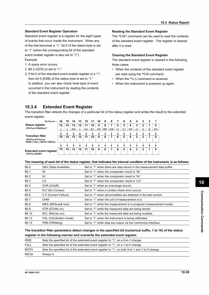
Com
munication C
omm
ands
10-39IM 755601-01E
10
Standard Event Register OperationStandard event register is a register for the eight typesof events that occur inside the instrument. When anyof the bits becomes a “1,” bit 5 of the status byte is setto “1” (when the corresponding bit of the standardevent enable register is also set to “1”).Example1. A query error occurs.2. Bit 2 (QYE) is set to “1.”3. If bit 2 of the standard event enable register is a “1”,
then bit 5 (ESB) of the status byte is set to “1.”In addition, you can also check what type of eventoccurred in the instrument by reading the contentsof the standard event register.
Reading the Standard Event RegisterThe *ESR? command can be used to read the contentsof the standard event register. The register is clearedafter it is read.
Clearing the Standard Event RegisterThe standard event register is cleared in the followingthree cases.• When the contents of the standard event register
are read using the *ESR command.• When the *CLS command is received.• When the instrument is powered up again.
10.3.4 Extended Event RegisterThe transition filter detects the changes of a particular bit of the status register and writes the result to the extendedevent register.
C.F
6MES
7 5 4 3 2 1 0N.C OVR LO HI IN DAVRCLCAL
8STR
9OHM
10110
12PRN
130
140
15
67 5 4 3 2 1 089101112131415
Status register:STATus:CONDition?
Transition filter
01415Extended event register 167 5 4 38910111213 2
67 5 4 3 2 18910111213141516
:STATus:FILTer<x>RISE | FALL | BOTH | NEVer
:STATus:EESR?
FILTer<x>→
The meaning of each bit of the status register, that indicates the internal condition of the instrument, is as follows:Bit 0 DAV (Data Available) Set to “1” when there are data stored in the measurement data buffer.Bit 1 IN Set to “1” when the comparator result is “IN.”
Bit 2 HI Set to “1” when the comparator result is “HI.”Bit 3 LO Set to “1” when the comparator result is “LO.”
Bit 4 OVR (OVeR) Set to “1” when an overrange occurs.Bit 5 N.C (No Contact) Set to “1” when a contact check error occurs.Bit 6 C.F (Current Failure) Set to “1” when abnormalities are detected in the test current.
Bit 7 OHM Set to “1” when the unit of measurement is Ω.Bit 8 MES (MESure& lock) Set to “1” while the measurement is in progress (measurement mode).
Bit 9 STR (SToRe on) Set to “1” while the measured data are being stored.Bit 10 RCL (ReCaLl on) Set to “1” while the measured data are being recalled.
Bit 12 CAL (CALibration mode) Set to “1” when the instrument is being calibrated.Bit 13 PRN (PRiNting) Set to “1” while data are output via the Centronics interface.
The transition filter parameters detect changes in the specified bit (numerical suffix, 1 to 16) of the statusregister in the following manner and overwrite the extended event register.RISE Sets the specified bit of the extended event register to “1”, on a 0-to-1 change.FALL Sets the specified bit of the extended event register to “1”, on a 1-to-0 change.BOTH Sets the specified bit of the extended event register to “1”, on both 0-to-1 and 1-to-0 change.
NEVer Always 0.
10.3 Status Report

10-40 IM 755601-01E
10.3.5 Output Queue and ErrorQueue
Output QueueThe output queue stores response messages for thequeries. For example, when the controller sends a:READ? command requesting the output of measureddata, data are stored in the output queue until they areread.As shown in the figure below, data are stored in orderand read from the oldest ones first. The output queueis also cleared for the following cases.• when a new message is received from the
controller.• When a deadlock occurs (see page 10-2)• When a device clear command (DCL or SDC) is
received.• When the power is turned ON again.The *CLS command cannot be used to clear the outputqueue. Bit 4 (MAV) of the status byte can be used tocheck whether or not the output queue is empty.
D1D2D1 D2
D1
Error QueueThe error queue stores the error number and messagewhen an error occurs. For example, if the controllersends an incorrect program message, the error number“113” and the message “Undefined header” are storedin the error queue when the error is displayed.The STATus:ERRor? query can be used to read thecontents of the error queue. As with the output queue,the messages are read from the oldest ones first.When the error queue overflows, the last message isreplaced by the message “–350, Queue overflow.”The error queue is also cleared for the following cases.• When the *CLS command is received.• When the power is turned ON again.Bit 2 (EAV) of the status byte can be used to checkwhether or not the error queue is empty.
10.3 Status Report
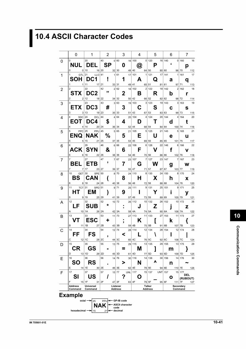
Com
munication C
omm
ands
10-41IM 755601-01E
10
10.4 ASCII Character Codes
0
1
2
3
4
5
6
7
10
11
12
13
14
15
16
17
NUL
SOH
STX
ETX
EOT
ENQ
ACK
BEL
BS
HT
LF
VT
FF
CR
SO
SI
20
21
22
23
24
25
26
27
30
31
32
33
34
35
36
37
40
41
42
43
44
45
46
47
50
51
52
53
54
55
56
57
60
61
62
63
64
65
66
67
70
71
72
73
74
75
76
77
100
101
102
103
104
105
106
107
110
111
112
113
114
115
116
117
120
121
122
123
124
125
126
127
130
131
132
133
134
135
136
137
140
141
142
143
144
145
146
147
150
151
152
153
154
155
156
157
160
161
162
163
164
165
166
167
170
171
172
173
174
175
176
177
0
1
2
3
4
5
6
7
8
9
A
B
C
D
E
F
0
1
2
3
4
5
6
7
8
9
A
B
C
D
E
F
10
11
12
13
14
15
16
17
18
19
1A
1B
1C
1D
1E
1F
20
21
22
23
24
25
26
27
28
29
2A
2B
2C
2D
2E
2F
30
31
32
33
34
35
36
37
38
39
3A
3B
3C
3D
3E
3F
40
41
42
43
44
45
46
47
48
49
4A
4B
4C
4D
4E
4F
50
51
52
53
54
55
56
57
58
59
5A
5B
5C
5D
5E
5F
60
61
62
63
64
65
66
67
68
69
6A
6B
6C
6D
6E
6F
70
71
72
73
74
75
76
77
78
79
7A
7B
7C
7D
7E
7F
0
1
2
3
4
5
6
7
8
9
10
11
12
13
14
15
16
17
18
19
20
21
22
23
24
25
26
27
28
29
30
31
32
33
34
35
36
37
38
39
40
41
42
43
44
45
46
47
48
49
50
51
52
53
54
55
56
57
58
59
60
61
62
63
64
65
66
67
68
69
70
71
72
73
74
75
76
77
78
79
80
81
82
83
84
85
86
87
88
89
90
91
92
93
94
95
96
97
98
99
100
101
102
103
104
105
106
107
108
109
110
111
112
113
114
115
116
117
118
119
120
121
122
123
124
125
126
127
GTL
SDC
PPC
GET
TCT
LLO
DCL
PPU
SPE
SPD
0
1
2
3
4
5
6
7
8
9
10
11
12
13
14
15
16
17
18
19
20
21
22
23
24
25
26
27
28
29
30
UNL
DEL
DC1
DC2
DC3
DC4
NAK
SYN
ETB
CAN
EM
SUB
ESC
FS
GS
RS
US
SP
!
”
#
$
%
&
’
(
)
*
+
,
-
.
/
0
1
2
3
4
5
6
7
8
9
:
;
<
=
>
?
@
A
B
C
D
E
F
G
H
I
J
K
L
M
N
O
P
Q
R
S
T
U
V
W
X
Y
Z
[
\
]
^
_
‘
a
b
c
d
e
f
g
h
i
j
k
l
m
n
o
p
q
r
s
t
u
v
w
x
y
z
|
~
DEL(RUBOUT)
0
1
2
3
4
5
6
7
8
9
10
11
12
13
14
15
16
17
18
19
20
21
22
23
24
25
26
27
28
29
30
UNT
0
1
2
3
4
5
6
7
8
9
10
11
12
13
14
15
16
17
18
19
20
21
22
23
24
25
26
27
28
29
30
AddressCommand
UniversalCommand
ListenerAddress
TalkerAddress
SecondaryCommand
25
15 21
PPU
NAKoctal
hexadecimal
GP-IB code
decimal
ASCII charactercode
Example
0 1 2 3 4 5 6 7

10-42 IM 755601-01E
10.5 About the IEEE.488.2-1992 Standard
The GP-IB interface of the instrument conforms to the IEEE 488.2-1992 Standard. This standard specifies that thefollowing 23 points be stated in the document. This section will describe these points.
1 Of the IEEE 488.1 interface functions, the subsets that are supportedSee section 9.1, “GP-IB Interface Functions and Specifications.”
2 The operation of the device when it is assigned an address outside the 0 to 30 range.The address of this instrument cannot be set to an address outside the 0 to 30 range.
3 Reaction of the device when the user changes the addressThe address is changed when a new address is set using the I/F key menu. The newaddress is valid until the next time it is changed.
4 Device settings at power-up. The commands that can be used at power-up.Basically, the previous settings are used (settings that existed when the power wasturned OFF). All commands can be used at power-up.
5 Message exchange optionsa Input buffer size
1024 byte
b Queries that return multiple response messagesSee the example of the commands given in section 10.2.
c Queries that create response data when the command syntax is being analyzedAll queries create response data when the command syntax is analyzed.
d Queries that create response data during receptionThere are no queries of which the response data are created upon receiving a sendrequest from the controller.
e Commands that have parameters the restrict one anotherSome commands, such as the :LIMit:PCNT:PLIMit and [:DATA], have parametersthat restrict unilaterally, but there are no commands that have parameters thatmutually restrict one another.
6 Items that are included in the functional or composite header elements constituting a command.See sections 10.1 and 10.2.
7 Buffer sizes that affect block data transmissionThe output queue is expanded to the appropriate size when block data are transmitted.
8 A list of program data elements that can be used in equations and their nesting limitationsEquations cannot be used.
9 Syntax of the responses to queriesSee the example of the commands given in section 10.2.
10 Communication between devices that do not follow the response syntax.See section 9.5, “Switching to the Talk-only Mode.”
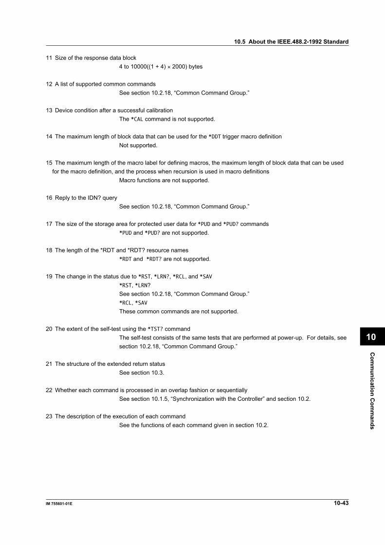
Com
munication C
omm
ands
10-43IM 755601-01E
10
11 Size of the response data block4 to 10000((1 + 4) × 2000) bytes
12 A list of supported common commandsSee section 10.2.18, “Common Command Group.”
13 Device condition after a successful calibrationThe *CAL command is not supported.
14 The maximum length of block data that can be used for the *DDT trigger macro definitionNot supported.
15 The maximum length of the macro label for defining macros, the maximum length of block data that can be usedfor the macro definition, and the process when recursion is used in macro definitions
Macro functions are not supported.
16 Reply to the IDN? querySee section 10.2.18, “Common Command Group.”
17 The size of the storage area for protected user data for *PUD and *PUD? commands*PUD and *PUD? are not supported.
18 The length of the *RDT and *RDT? resource names*RDT and *RDT? are not supported.
19 The change in the status due to *RST, *LRN?, *RCL, and *SAV*RST, *LRN?See section 10.2.18, “Common Command Group.”*RCL, *SAVThese common commands are not supported.
20 The extent of the self-test using the *TST? commandThe self-test consists of the same tests that are performed at power-up. For details, seesection 10.2.18, “Common Command Group.”
21 The structure of the extended return statusSee section 10.3.
22 Whether each command is processed in an overlap fashion or sequentiallySee section 10.1.5, “Synchronization with the Controller” and section 10.2.
23 The description of the execution of each commandSee the functions of each command given in section 10.2.
10.5 About the IEEE.488.2-1992 Standard
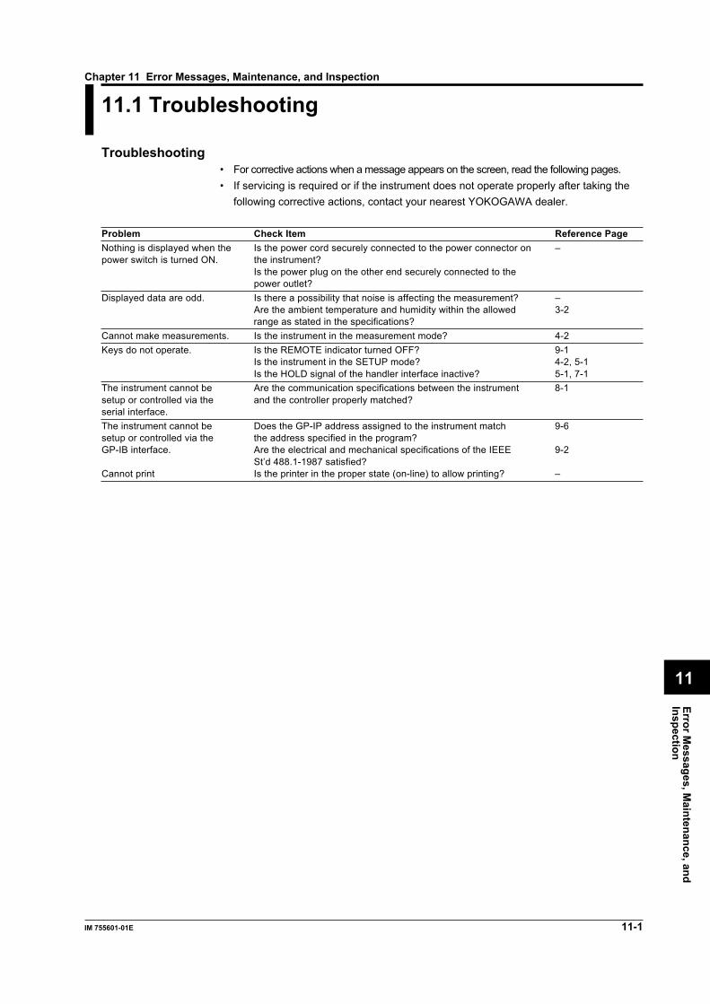
Error Messages, M
aintenance, andInspection
11-1IM 755601-01E
11
Chapter 11 Error Messages, Maintenance, and Inspection
LOCAL keyGP-IB connector
11.1 Troubleshooting
Troubleshooting• For corrective actions when a message appears on the screen, read the following pages.• If servicing is required or if the instrument does not operate properly after taking the
following corrective actions, contact your nearest YOKOGAWA dealer.
Problem Check Item Reference PageNothing is displayed when the Is the power cord securely connected to the power connector on –power switch is turned ON. the instrument?
Is the power plug on the other end securely connected to thepower outlet?
Displayed data are odd. Is there a possibility that noise is affecting the measurement? –Are the ambient temperature and humidity within the allowed 3-2range as stated in the specifications?
Cannot make measurements. Is the instrument in the measurement mode? 4-2Keys do not operate. Is the REMOTE indicator turned OFF? 9-1
Is the instrument in the SETUP mode? 4-2, 5-1Is the HOLD signal of the handler interface inactive? 5-1, 7-1
The instrument cannot be Are the communication specifications between the instrument 8-1setup or controlled via the and the controller properly matched?serial interface.The instrument cannot be Does the GP-IP address assigned to the instrument match 9-6setup or controlled via the the address specified in the program?GP-IB interface. Are the electrical and mechanical specifications of the IEEE 9-2
St’d 488.1-1987 satisfied?Cannot print Is the printer in the proper state (on-line) to allow printing? –

11-2 IM 755601-01E
11.2 Messages and Corrective Actions
Error MessagesIf an error occurs during operation, an error code (example: ) may appear on thescreen.This section describes the meanings of the error messages and the corrective actionswhich they require.For errors that occur while operating the instrument remotely via the communicationinterface, the “:STATus:ERRor?” query can be used to check the error code andmessage.
Example :STATus:ERRor? →800, ”Cannot be excuted while running”
Error in communication command (-100 to -199)Code Message Probable Cause/Corrective Action Page-102 Syntax error There is a syntax error other than the Chapter 10
codes listed below.-103 Invalid separator Use a comma to separate the data. 10-1-104 Data type error Write using the correct data form. 10-5, 10-6-105 GET not allowed. – –-108 Parameter not allowed Check the number of data points. 10-5, Section 10.2-109 Missing parameter Check the number of data points. 10-5, Section 10.2-111 Header separator error Use a space to separate the header and data.10-1-112 Program mnemonic too long The length of a mnemonic (alphanumerical Section 10.2
character string) must be less than or equalto 12 characters.
-113 Undefined header Check the header. Section 10.2-120 Numeric data error A number is needed for the <NRf> form. 10-5-123 Exponent too large The absolute value of the exponent in the 10-5, Section 10.2
<NR3> form must be less than or equal to32000.
-124 Too many digits The number of digits of the mantissa in the 10-5, Section 10.2 <NRf> form must be less than or equal to255 excluding the preceding “0.”
-128 Numeric data not allowed Write in a data form other than the <NRf> 10-5, Section 10.2form.
-131 Invalid suffix Check the unit and multiplier of the 10-5<resistance> and <time>.
-134 Suffix too long Check the unit and multiplier of the 10-5<resistance> and <time>.
-138 Suffix not allowed Units and multipliers other than those for 10-5<resistance> and <time> cannot be used.
-141 Invalid character data Select character data from the selections Section 10.2available in (...|...|...).
-144 Character data too long The length of character data is less than or Section 10.2equal to 12 characters.
-148 Character data not allowed Write in a data form other than character Section 10.2data form.
-150 String data error String data cannot be used. Section 10.2-158 String data not allowed String data cannot be used. Section 10.2-161 Invalid block data Block data cannot be used. 10-6, Section 10.2-168 Block data not allowed Block data cannot be used. 10-6, Section 10.2-171 Invalid expression Expression data cannot be used. Section 10.2-178 Expression data not allowed Expression data cannot be used. Section 10.2-181 Invalid outside macro definition Macro functions defined in IEEE488.2 are –
not supported.

Error Messages, M
aintenance, andInspection
11-3IM 755601-01E
11
11.2 Messages and Corrective Actions
Errors in communication execution (-200 to -299)Code Message Probable Cause/Corrective Action Page-221 Setting conflict Check the relevant setting values. Section 10.2-222 Data out of range Check the setting range for dat.a Section 10.2-223 Too much data Check the length of bytes of data. Section 10.2-224 Illegal parameter value Check the setting range for data. Section 10.2-241 Hardware missing Check the existence of options. –
Errors in communication query (-400 to -499)Code Message Probable Cause/Corrective Action Page-410 Query INTERRUPTED Check the order of transmission and 10-2
reception.-420 Query UNTERMINATED Check the order of transmission and 10-2
reception.-430 Query DEADLOCKED The length of a program message including 10-2
the <PMT> is less than or equal to 1024 bytes.-440 Query UNTERMINATED after indefinite response Do not specify a query after the *IDN? or –
*OPT? command.
Errors in System Operation (800 to 899)Code Message Probable Cause/Corrective Action Page800 Cannot be executed while running Stop the measurement (SETUP mode) Chapter 4
before executing.801 Cannot be executed when HOLD is active Turn OFF the HOLD signal before executing. 5-1, 7-1810 Parameter out of range Set a value within the range. –812 Cannot set this parameter in PCNT limit mode Limit values cannot be set in Ω when the 4-5
limit mode is set to %.813 Cannot set this parameter in OHM limit mode Limit values and reference value cannot be 4-7
set when the limit mode is set to R.814 Cannot set PCNT display mode in OHM limit mode To change the measurement display to %, 4-2, 4-3, 5-2
set the limit mode to % and set the referencevalue.
815 Lower limit value is larger than upper limit Set the limits so that HI is greater than LO. 4-5, 4-7830 No measured data has been stored Store measured data before executing. 6-1831 Cannot store measured data while recall is active Turn OFF the recall function before 6-1
executing.832 Cannot recall measured data while store is active Turn OFF the store function before 6-1
executing.850 Cannot be executed while printing Terminate printing before executing. 6-3860 Centronics printer error Power up the printer again. –861 Centronics printer is off line Set the printer to on-line. –862 Centronics printer is out of paper Put paper in the printer. –864 Centronics cannot detect printer Turn ON the printer. –
Check the connection.870 Must be executed in adjust mode Switch to the range adjustment mode before –
executing.871 ZERO measure failure Check the connection to the standard –
resistor.872 FULL measure failure Check the connection to the standard –
resistor.Check the input parameter value.
873 Cannot execute ZERO measure –874 Cannot write to EEPROM –875 Cannot change the adjusting range When the full scale measurement of a range 11-8
is performed properly, the rangeautomatically increments by 1

11-4 IM 755601-01E
Error in System Operation (901 to 905)Code Message Probable Cause/Corrective Action Page900 ROM checksum error Servicing is required –901 Backup lithium battery low Servicing is required for battery replacement. –902 Setup param. checksum error (other than comm.) Servicing is required –903 Setup param. checksum error (comm.) Servicing is required –905 EEPROM checksum error Servicing is required –If an error code in the range 902 to 905 is displayed at power-up, the error remains on the screen until a key is pressed.For system errors (900 to 905), the ":STATus:ERRor?" query cannot be used to inquire error codes and error messages.
Error in System Operation (Communications, 912)Code Message Probable Cause/Corrective Action Page912 Fatal error in Communication-driver Servicing is required –
Warning (Communications, 5)Code Message Probable Cause/Corrective Action Page5 *OPC/? Exists in message Place the *OPC or *OPC? command at the –
end of the program message.
Miscellaneous (-350, -390)Code Message Probable Cause/Corrective Action Page-350 Queue overflow This error only occurs for the 10-40
":STATus:ERRor?" query.The error code does not appear on theinstrument’s display.
-390 Overrun error (RS232 only) Lower the baud rate. –This message sometimes appears if acommand is sent during the [measurementtime].
11.2 Messages and Corrective Actions

Error Messages, M
aintenance, andInspection
11-5IM 755601-01E
11
11.3 Self Test
KeysNORMAL
MEAS&LOCK
SAMPLE
EXTERNAL
REFERENCE
MANUAL
FAST
HI
HI LIMITEXIT
SETUP/MEAS
CHECK
MISCI/F
MEASTIME
STOREDATA
RECALLDATA
LOCAL ENTER
LIMITMODE
TRIGMODE
SHIFT
R/% REF LIMIT
TRIG7
1
0 .
2 3
54 6
8 9
LO LIMIT
IN
LOMΩ M Ω
k Ω
Ω,%
kΩ Ω
Ω
% %
HIGHSPEED
STOREDATA
RECALLDATA CHECK REMOTE
ProcedureThe items that are specified or selected are confirmed when the ENTER (Ω,%) key ispressed. To exit from a menu in the middle of the operation, press the EXIT (R/%) key.
Switching to the SETUP mode1. Press the
SHIFT
SETUP/MEAS
R/% key to switch to the SETUP mode. If the “MEAS & LOCK”indicator is off, this operation is not necessary.
2.
3.
(Eom)
MISCSHIFTREF LIMIT
k Ω
ENTER
Ω,%
[Main display]
4. 6.
ENTER
Ω,%5.REF LIMIT

11-6 IM 755601-01E
11.3 Self Test
Key testSelect “KEY” at step 5. To cancel a key test that is in progress, press the
SETUP/MEAS
R/% key.
LED testSelect “LEd” at step 5.
ROM version checkSelect “rom” at step 5. Version information is displayed for approximately 1 s, and thedisplay returns to the top menu of the SETUP mode.
Handler interface testSelect “HAnd” at step 5.
ExplanationThe self-test can be performed on the following items. If any part of the test fails, contactyour nearest YOKOGAWA dealer.
Key testTests whether or not the front panel keys are operating correctly. If the correct numbercorresponding to the pressed key (00 to 18 correspond to the SHIFT key to the Ω/% keyexcluding the R/% key) appears on the seven-segment display, the key is operatingcorrectly.
Indicator testTests whether or not the seven-segment characters on the screen and other indicatorsare operating correctly. If all the LEDs turn ON at once, then each one in order, the testis indicates proper operation.
ROM version checkThe Software ROM version used by the instrument can be checked.
Handler interface testTests whether or not the output signal of the handler interface is normal. The HI, IN, LO,NO CONTACT, EOM, and INDEX signals are activated in order. If the output of allsignals is confirmed, the test is successful.
Note• The key and indicator tests can be aborted in the middle of the test by pressing the EXIT(R/
%) key.• ROM version and handler interface tests cannot be aborted in the middle of the test. Please
wait until the test terminates.

Error Messages, M
aintenance, andInspection
11-7IM 755601-01E
11
11.4 Adjustments
To maintain high measurement accuracy, we recommend that the instrument beadjusted once a year.
Instruments to PrepareStandard resistor
Nominal Value Accuracy1 Ω ±50 ppm10 Ω ±25 ppm100 Ω to 100 kΩ ±15ppm1 MΩ ±25 ppm10 MΩ ±50 ppm100 MΩ ±100 ppm
Recommended instrument: 4808 (Fluke), 2792 (YOKOGAWA)
Environment and Conditions while making the adjustmentAmbient temperature: 23±1°CRelative humidity: 45 to 75%RHSupply voltage: 100 V±5%Frequency: (50/60 Hz)±1 HzWarm-up: At least 2 hours for the standard resistor and 60 minutes for this
instrument before making the adjustment
Precautions while making adjustmentsConnect the power cord of the instrument to a three-pole power outlet that has aprotective grounding terminal.

11-8 IM 755601-01E
Wiring ProcedureWhen using Fluke’s 4808
Standard resistorDANGER
HIGH VOLTAGE
I+ I- Guard
Hi Lo
Instrument being adjusted
L CUR L POT H POT H CUR
NoteUse shielded wires, and connect the shield to the Guard terminal of the 4808.
When using 2792 (by YOKOGAWA)
L CUR L POT H POT H CUR
Standard resistor
Instrument being adjusted
Shorted Input
L CUR L POT H POT H CUR
Instrument being adjusted
Procedure1. Prepare and warm up the standard resistor.2. Turn ON the power while pressing the Ω/% key. Continue pressing the Ω/% key
until “AdJ” appears on the main display.3. Pressing the ENTER key will cause “0.00000” (755611)*1 to blink.4. Short the input as described in the section “Wiring Procedure, Shorted Input” and
press the ENTER key.The instrument makes a zero measurement for all ranges. If the measurementcompletes successfully, “1.00000” Ω (755611)*2 blinks on the main display.If the zero measurement fails, an error is displayed and the routine returns to step 3.
5. Connect a standard resistor of the nominal value that is displayed on the maindisplay to the instrument.
6. Enter the resistance of the standard resistor using 5.5 digits, and press the ENTERkey. On the 755601, entering the 5.5th digit will cause the left most digit to shift tothe left and will no longer be displayed.
7. The measured value using the new adjusted value is displayed for approximatelythree seconds. Then, an [Ok] is displayed (after a full scale measurement of therelevant range) and the next range (10.0000 Ω, for 755611) blinks on the display.
8. Repeat steps 5 to 7 until the adjustment for the 100 MΩ range is complete.9. After making the adjustment for the 100 MΩ range, “WritE” is displayed. When the ENTER
key is pressed, the adjusted values are written to the EEPROM. Then, “AdJ” is displayedon the main display and the adjustment completes. Reboot the instrument.
11.4 Adjustments

Error Messages, M
aintenance, andInspection
11-9IM 755601-01E
11
Completing the adjustment in the middle of the range5. Press the ENTER key when the adjustment range is blinking on the main display.
“WritE” is displayed.6. When the ENTER key is pressed, the adjusted values existing in the range previous
to that which was blinking are written to the EEPROM and the adjustmentterminates. Reboot the instrument.
Canceling the range adjustment5. Press the EXIT(R/%) key when the adjustment range is blinking on the main
display. The adjustment is aborted and “AdJ” is displayed. In this case, theadjusted values are not updated.
*1 “0.0000” Ω blinks for the 755601.*2 “1.0000” Ω blinks for the 755601.
ExplanationChange in the value entryWhile entering values, the <(REF) and >(LIMIT) keys become backspace and clear keys,respectively.
Adjustment rangeThe adjustment ranges are as follows:1 Ω, 10 Ω, 100 Ω, 1 kΩ, 10 kΩ, 100 kΩ, 1 MΩ, 10 MΩ, and 100 MΩ
11.4 Adjustments

11-10 IM 755601-01E
Communication Commands Related to the Adjustment MethodThe functions in the CALibrate group are valid only during the range adjustment mode. Read pages 10-1 to 10-4carefully before executing commands in this group.
:CALibrate : ADJust CANCel
RANGe
STATe
?
?
;
WRITe
ZERO
FULL ? <Resistance>
:
MIN
DOWN
<Space> <Resistance>
?
<Space> OFF
ON
<NRf>
?
11.4 Adjustments
:CALibrate?Function Queries all settings related to adjustments.Syntax :CALibrate?
Example :CALIBRATE? →:CALIBRATE:ADJUST:STATE 1;
RANGE 1.0E+05
:CALibrate:ADJust?Function Queries all setting related to range adjustment.Syntax :CALibrate:ADJust?
Example :CALIBRATE:ADJUST?
→:CALIBRATE:ADJUST:STATE 1;
RANGE 1.0E+05
Description The response is the same as that of the“:CALibrate?” query.
:CALibrate:ADJust:CANCelFunction Terminates the range adjustment without
writing the adjusted values to the EEPROM.Syntax :CALibrate:ADJust:CANCel
Example :CALIBRATE:ADJUST:CANCEL
Description This command is equivalent to the“:CALibrate:ADJust[:STATe] OFF” command.
:CALibrate:ADJust:FULL?Function Executes the full scale measurement for the
current range and determines the new gainadjustment value. At the same time, queriesthe value that is measured using the newadjusted value.
Syntax :CALibrate:ADJust:FULL? <Resistance>
<Resistance> = Resistance of the standard
resistor
0.00000 Ω to 120.000 MΩ (The setting
resolution is 1/10 of the display
resolution)
Response <NR3> form
Example :CALIBRATE:ADJUST:FULL? 100.001KOHM
→1.00001E+05 (Normal)
:CALIBRATE:ADJUST:FULL? 100.001KOHM
→9.9E+37 (When an error occured)
Description • If the result of the full scale measurement ofthe range is inappropriate, an error 872occurs, and “9.9E+37” is returned as aresponse. In addition, the adjustment doesnot move to the next range.
• If the full scale measurement is completedsuccessfully, the adjustment automaticallymoves to the next range. Therefore, if youwish to make another full scale measurementat the same range, issue the“:CALibrate:ADJust:RANGe DOWN” commandto set the adjustment range back by onebefore making the measurement again.
• If the zero measurement“:CALibrate:ADJust:ZERO” has not beenexecuted successfully, this command cannotbe executed. Otherwise, an error 873 occurs.

11-11IM 755601-01E
Error Messages, M
aintenance, andInspection
11
:CALibrate:ADJust:RANGeFunction Sets the adjustment range or queries the
current setting.Syntax :CALibrate:ADJust:RANGe <Resistance>|
DOWN|MIN
:CALibrate:ADJust:RANGe?
<Resistance> = 1, 10, 100, 1K, 10K, 100K,
1M, 10M, 100M (Ω)
DOWN = One range below the current range (No
change if the current range is 1 Ω)
MIN = 1 Ω
Response <NR3> form
Example :CALIBRATE:ADJUST:RANGE 100KOHM
:CALIBRATE:ADJUST:RANGE?
→:CALIBRATE:ADJUST:RANGE 1.0E+05
Description • The range adjustment starts at 1 Ω, andautomatically moves to the next higher rangeevery time the full scale measurement is made.Thus, this command cannot be used to specify arange that is higher than the current range.
• This command is used to redo a full scalemeasurement of a range.
:CALibrate:ADJust[:STATe]Function Starts or aborts the range adjustment or queries
whether or not the range adjustment is inprogress.
Syntax :CALibrate:ADJust[:STATe] <Boolean>
:CALibrate:ADJust:STATe?
<Boolean> = ON(1) Starts the range
adjustment.
= OFF(0) Terminates the range
adjustment without
writing the adjusted
values to the EEPROM.
Response 1|0
Example :CALIBRATE:ADJUST:STATE ON
:CALIBRATE:ADJUST:STATE?
→:CALIBRATE:ADJUST:STATE 1
Description The OFF(0) setting is equivalent to executingthe “:CALibrate:ADJust:CANCel” command.
:CALibrate:ADJust:WRITeFunction Writes the adjusted values to the EEPROM and
terminates range adjustment.Syntax :CALibrate:ADJust:WRITe
Example :CALIBRATE:ADJUST:WRITE
Description This command cannot be executed unless newzero and gain values of at least one range aredetermined. If not, an error 874 occurs. The“:CALibrate:ADJust:RANGe?” query can be usedto check whether new adjusted values have beendetermined. If the response is “1.0E+00”(1 Ωrange), then full standard measurement has notbeen performed on any of the ranges, and newadjusted values have not been determined.
:CALibrate:ADJust:ZEROFunction Executes the zero measurement on all ranges
at once to determine the new zero adjustmentvalue.
Syntax :CALibrate:ADJust:ZERO
Example :CALIBRATE:ADJUST:ZERO
Description If the result of the zero measurement isinappropriate, an error 871 occurs.Perform the zero measurement once at thebeginning of the range adjustment sequence.Executing this command in the middle of therange adjustment will automatically set therange to 1 Ω. This command is used to redothe range adjustment from the beginning.
11.4 Adjustments

11-12 IM 755601-01E
11.5 Replacing the Power Fuse
WARNING• To prevent the possibility of fire, use only a fuse having the specified rating
(voltage, current, and type).• Make sure to turn OFF the instrument and unplug the power cord before
replacing the fuse.• Never short the fuse holder.
Specified RatingThe power fuse used on this instrument is specified as follows.Maximum rated voltage: 250 VMaximum rated current: 315 mA (100/120 V), 160 mA (220/240 V)Type: Time lagStandard: VDE/SEMKO/UL/CSA/SEV certifiedPart number: A1345EF (100/120 V), A1342EF (220/240 V)
Replacement ProceduresFollow the procedures below to replace the power fuse.1. Turn OFF the power switch.2. Unplug the power cord from the power outlet.3. Press the fuse holder section to the right of the power connector with a Philips
screwdriver, for example, and turn it to the left in order to remove the fuse holder.Place a new fuse in the fuse holder, and place the fuse holder back in its originalposition.

Specifications
12-1IM 755601-01E
12
Chapter 12 Specifications
LOCAL keyGP-IB connector
12.1 Input Specifications
RangeWhen the measurement display is in absolute values (R)
Range Maximum Display Resolution Test Current755601 755611 755601 755611
1 Ω 1.2000 1.20000 100 µΩ 10 µΩ 100 mA10 Ω 12.000 12.0000 1 mΩ 100 µΩ 100 mA100 Ω 120.00 120.000 10 mΩ 1 mΩ 10 mA1 kΩ 1.2000 1.20000 100 mΩ 10 mΩ 1 mA10 kΩ 12.000 12.0000 1 Ω 100 mΩ 100 µA100 kΩ 120.00 120.000 10 Ω 1 Ω 50 µA1 MΩ 1.2000 1.20000 100 Ω 10 Ω 5 µA10 MΩ 12.000 12.0000 1 kΩ 100 Ω 500 nA100 MΩ 120.00 120.000 10 kΩ 1 kΩ 50 nA
When the measurement display in deviations (%)• Percent limit (PLmt) is 9.99
Range of Reference Values Applied Used Range Display Range0.0001 Ω to 1.0009 Ω 1 Ω1.001 Ω to 10.009 Ω 10 Ω10.01 Ω to 100.09 Ω 100 Ω -99.999%0.1001 kΩ to 1.0009 kΩ 1 kΩ to 19.999%1.001 kΩ to 10.009 kΩ 10 kΩ (for 755611)*1
10.01 kΩ to 100.09 kΩ 100 kΩ0.1001 MΩ to 1.0009 MΩ 1 MΩ1.001 MΩ to 10.009 MΩ 10 MΩ10.01 MΩ to 120.00 MΩ 100 MΩ
*1 -99.99% to 19.99% for 755601.
• Percent limit (PLmt) is 99.9
Range of Reference Values Applied Used Range Display Range0.001 Ω to 1.009 Ω 10 Ω1.01 Ω to 10.09 Ω 100 Ω10.1 Ω to 100.9 Ω 1 kΩ -99.99%0.101 kΩ to 1.009 kΩ 10 kΩ to 199.99%1.01 kΩ to 10.09 kΩ 100 kΩ (for 755611)*2
10.1 kΩ to 100.9 kΩ 1 MΩ0.101 MΩ to 1.009 MΩ 10 MΩ1.01 MΩ to 120.0 MΩ 100 MΩ
*2 -99.9% to 199.9% for 755601.
Accuracy (±(% of reading + digits))For 755601 (1 digit = 0.01%, one year after adjustment)
Range NORMAL FAST HIGH SPEED1 Ω 0.02+2 0.02+3 0.02+510 Ω 0.02+1 0.02+2 0.02+4100 Ω 0.02+1 0.02+2 0.02+41 kΩ 0.015+1 0.015+2 0.015+410 kΩ 0.015+1 0.015+2 0.015+4100 kΩ 0.015+1 0.015+2 0.015+41 MΩ 0.02+1 0.1+2 0.1+410 MΩ 0.04+1 0.3+2 0.3+4100 MΩ 0.2+2
* Accuracy at 1 Ω range measuring 0.1 Ω or less (% of reading +Ω) is as follows.One year after adjustmentNORMAL: 0.02+0.0002FAST: 0.02+0.0003HIGH SPEED: 0.02+0.0005
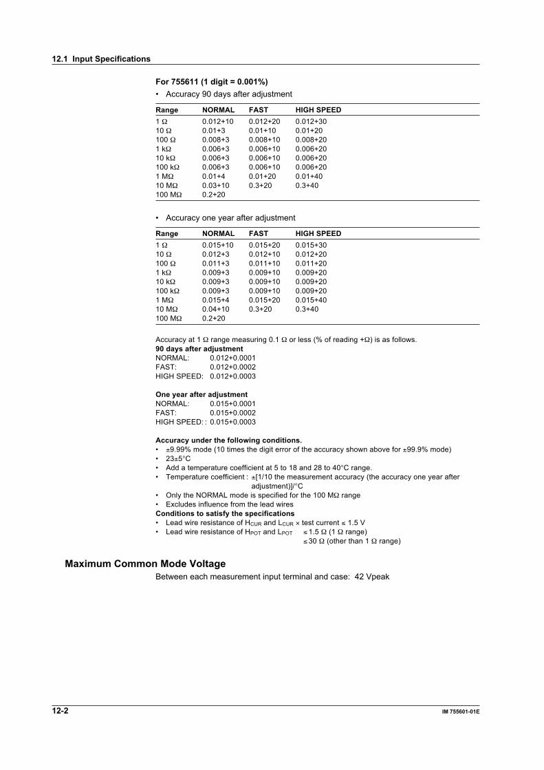
12-2 IM 755601-01E
12.1 Input Specifications
For 755611 (1 digit = 0.001%)• Accuracy 90 days after adjustment
Range NORMAL FAST HIGH SPEED1 Ω 0.012+10 0.012+20 0.012+3010 Ω 0.01+3 0.01+10 0.01+20100 Ω 0.008+3 0.008+10 0.008+201 kΩ 0.006+3 0.006+10 0.006+2010 kΩ 0.006+3 0.006+10 0.006+20100 kΩ 0.006+3 0.006+10 0.006+201 MΩ 0.01+4 0.01+20 0.01+4010 MΩ 0.03+10 0.3+20 0.3+40100 MΩ 0.2+20
• Accuracy one year after adjustment
Range NORMAL FAST HIGH SPEED1 Ω 0.015+10 0.015+20 0.015+3010 Ω 0.012+3 0.012+10 0.012+20100 Ω 0.011+3 0.011+10 0.011+201 kΩ 0.009+3 0.009+10 0.009+2010 kΩ 0.009+3 0.009+10 0.009+20100 kΩ 0.009+3 0.009+10 0.009+201 MΩ 0.015+4 0.015+20 0.015+4010 MΩ 0.04+10 0.3+20 0.3+40100 MΩ 0.2+20
Accuracy at 1 Ω range measuring 0.1 Ω or less (% of reading +Ω) is as follows.90 days after adjustmentNORMAL: 0.012+0.0001FAST: 0.012+0.0002HIGH SPEED: 0.012+0.0003
One year after adjustmentNORMAL: 0.015+0.0001FAST: 0.015+0.0002HIGH SPEED: : 0.015+0.0003
Accuracy under the following conditions.• ±9.99% mode (10 times the digit error of the accuracy shown above for ±99.9% mode)• 23±5°C• Add a temperature coefficient at 5 to 18 and 28 to 40°C range.• Temperature coefficient : ±[1/10 the measurement accuracy (the accuracy one year after
adjustment)]/°C• Only the NORMAL mode is specified for the 100 MΩ range• Excludes influence from the lead wiresConditions to satisfy the specifications• Lead wire resistance of HCUR and LCUR × test current ≤ 1.5 V• Lead wire resistance of HPOT and LPOT ≤1.5 Ω (1 Ω range)
≤30 Ω (other than 1 Ω range)
Maximum Common Mode VoltageBetween each measurement input terminal and case: 42 Vpeak

Specifications
12-3IM 755601-01E
12
12.2 Trigger Specifications
Trigger mode: INTERNAL, EXTERNAL, MANUALTrigger delay: Setting valid when the trigger mode is set to EXTERNAL or MANUAL
Setting range: 0 to 1000 ms (resolution: 0.1 ms)Trigger edge: Select rising or falling edge
Setting valid only when the trigger mode is set to EXTERNALTrigger ignore time (Time until the next trigger becomes valid)Types of Measurement Time Trigger Input Ignore TimeNORMAL Measurement time + 25 msFAST/HIGH SPEED Measurement time + 10 ms (EOM pulse width of 0.1 ms, 5 ms, and 10 ms)
Measurement time + 15 ms (EOM pulse width of 15 ms)
Auto Sampling (Only when the trigger mode is set to INTERNAL)Measurement Interval*
NORMAL 50 msFAST 20 msHIGH SPEED 10 ms* Add 5 ms when the contact check is ON.* Add 5 ms when the measurement range is 10 MΩ* Add 50 ms when the measurement range is 100 MΩ
12.3 Measurement Time Specifications
Mode Power Frequency Measurement TimeNORMAL 60 Hz 19.9 ms
50 Hz 23.2 msFAST 5.7 msHIGH SPEED 2.8 ms• Automatically detects the power frequency at power-up.• Measurement time : From the trigger input to the falling edge of the EOM signal (when the trigger mode is set to EXTERNAL)• Add 2 ms when the contact check is ON (before measurement).• Add 1 ms when the contact check is ON (after measurement).• Add the trigger delay time if it is set.• Add 4 ms when the measurement range is 10 MΩ.• Add 50 ms when the measurement range is 100 MΩ
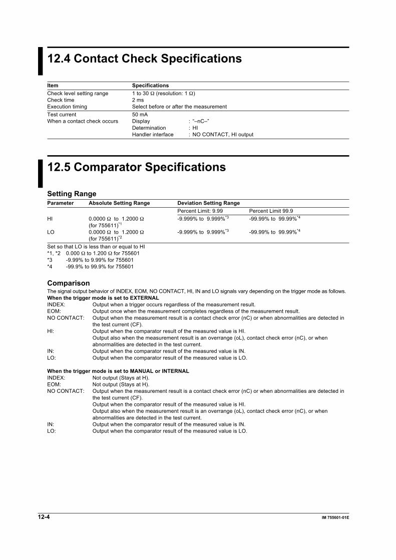
12-4 IM 755601-01E
12.4 Contact Check Specifications
Item SpecificationsCheck level setting range 1 to 30 Ω (resolution: 1 Ω)Check time 2 msExecution timing Select before or after the measurementTest current 50 mAWhen a contact check occurs Display : “–nC–”
Determination : HIHandler interface : NO CONTACT, HI output
12.5 Comparator Specifications
Setting RangeParameter Absolute Setting Range Deviation Setting Range
Percent Limit: 9.99 Percent Limit 99.9HI 0.0000 Ω to 1.2000 Ω -9.999% to 9.999%*3 -99.99% to 99.99%*4
(for 755611)*1
LO 0.0000 Ω to 1.2000 Ω -9.999% to 9.999%*3 -99.99% to 99.99%*4
(for 755611)*2
Set so that LO is less than or equal to HI*1, *2 0.000 Ω to 1.200 Ω for 755601*3 -9.99% to 9.99% for 755601*4 -99.9% to 99.9% for 755601
ComparisonThe signal output behavior of INDEX, EOM, NO CONTACT, HI, IN and LO signals vary depending on the trigger mode as follows.When the trigger mode is set to EXTERNALINDEX: Output when a trigger occurs regardless of the measurement result.EOM: Output once when the measurement completes regardless of the measurement result.NO CONTACT: Output when the measurement result is a contact check error (nC) or when abnormalities are detected in
the test current (CF).HI: Output when the comparator result of the measured value is HI.
Output also when the measurement result is an overrange (oL), contact check error (nC), or whenabnormalities are detected in the test current.
IN: Output when the comparator result of the measured value is IN.LO: Output when the comparator result of the measured value is LO.
When the trigger mode is set to MANUAL or INTERNALINDEX: Not output (Stays at H).EOM: Not output (Stays at H).NO CONTACT: Output when the measurement result is a contact check error (nC) or when abnormalities are detected in
the test current (CF).Output when the comparator result of the measured value is HI.Output also when the measurement result is an overrange (oL), contact check error (nC), or whenabnormalities are detected in the test current.
IN: Output when the comparator result of the measured value is IN.LO: Output when the comparator result of the measured value is LO.

Specifications
12-5IM 755601-01E
12
12.6 Other Specifications
Item SpecificationsMemory function Store up to 2000 data points of measured data.Function used to detect Detects abnormalities in the test current during measurement.abnormalities in the test current Display: “–CF–”
Determination: HIHandler output: NO CONTACT, HI output
12.7 Handler Interface Specifications
Connector For details contact your nearest YOKOGAWA dealerSignal NamePin No. Signal Name Active Condition Input/Output Function/Operation1 HI L Output L when the comparator result is HI.2 IN L Output L when the comparator result is IN.3 LO L Output L when the comparator result is LO.4 NO CONTACT L Output L when a contact check error occurs or when abnormalities
are detected in the test current.7 +12V — Output Power supply8 EXT TRIG Specified edge Input External trigger signal9 EOM L Output L after the measurement is completed and after the output of
the comparator result L*1
10 HOLD L Input Key lock*2
11 INDEX L Output H when trigger is input, L when data collection is completed L*3
14 COM — — Common*1 Select the pulse width from 0.1, 5, 10, 15 ms. The default setting is 10 ms.*2 When active (L), the instrument switches to the measurement mode (trigger mode is set to EXTERNAL) regardless of the
current mode (measurement/SETUP) and makes measurements. All keys except the R/% and STORE DATA keys aredisabled (key lock). When the signal changes from L to H the key is enabled. Thus, the SETUP/MEAS key can bepressed to switch to the SETUP mode and make setting changes to the instrument.
*3 When contact check is ON (after measurement), the signal is set to L when the contact check is completed.
Input teriminal (EXT TRIG, HOLD)Input voltage: LO level ≤ 1 V
HI level = 12 V or openInput current (at LO level): 7 mAMaximum input voltage: 12 VMinimum pulse width: 100 µs
Output terminal (HI, IN, LO, NO CONTACT, EOM, INDEX)Output format: Open collectorIsolation: Photo coupler isolationRated output voltage: LO level ≤ 0.8 VMaximum load current: 25 mAMaximum load voltage: 30 V
Power supply (+12 V)Maximum load current: 50 mA
Maximum common mode voltageBetween each terminal (pin) and case: 42 Vpeak
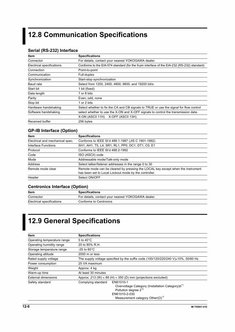
12-6 IM 755601-01E
12.8 Communication Specifications
Serial (RS-232) InterfaceItem SpecificationsConnector For details, contact your nearest YOKOGAWA dealer.Electrical specifications Conforms to the EIA-574 standard (for the 9-pin interface of the EIA-232 (RS-232) standard)Connection Point-to-pointCommunication Full-duplexSynchronization Start-stop synchronizationBaud rate Select from 1200, 2400, 4800, 9600, and 19200 bit/sStart bit 1 bit (fixed)Data length 7 or 8 bitsParity Even, odd, noneStop bit 1 or 2 bitsHardware handshaking Select whether to fix the CA and CB signals to TRUE or use the signal for flow controlSoftware handshaking select whether to use the X-ON and X-OFF signals to control the transmission data.
X-ON (ASCII 11H) X-OFF (ASCII 13H)Received buffer 256 bytes
GP-IB Interface (Option)Item SpecificationsElectrical and mechanical spec. Conforms to IEEE St’d 488.1-1987 (JIS C 1901-1992)Interface Functions SH1, AH1, T5, L4, SR1, RL1, PP0, DC1, DT1, C0, E1Protocol Conforms to IEEE St’d 488.2-1992Code ISO (ASCII) codeMode Addressable mode/Talk-only modeAddress Select talker/listener addresses in the range 0 to 30Remote mode clear Remote mode can be cleared by pressing the LOCAL key except when the instrument
has been set to Local Lockout mode by the controller.Header Select ON/OFF
Centronics Interface (Option)Item SpecificationsConnector For details, contact your nearest YOKOGAWA dealer.Electrical specifications Conforms to Centronics
12.9 General Specifications
Item SpecificationsOperating temperature range 5 to 40°COperating humidity range 20 to 80% R.H.Storage temperature range -25 to 60°COperating altitude 2000 m or lessRated supply voltage The supply voltage specified by the suffix code (100/120/220/240 V)±10%, 50/60 HzPower consumption 25 VA maximumWeight Approx. 4 kgWarm-up time At least 30 minutesExternal dimensions Approx. 213 (W) × 88 (H) × 350 (D) mm (projections excluded)Safety standard Complying standard EN61010-1
Overvoltage Category (Installation Category)II*1
Pollution degree 2*2
EN61010-2-030Measurement category Other(O)*7
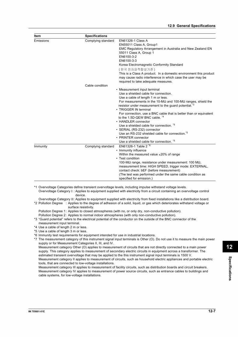
Specifications
12-7IM 755601-01E
12
Item SpecificationsEmissions Complying standard EN61326-1 Class A
EN55011 Class A, Group1EMC Regulatory Arrangement in Australia and New Zealand EN55011 Class A, Group 1EN6100-3-2EN6100-3-3Korea Electromagnetic Conformity Standard
This is a Class A product. In a domestic environment this productmay cause radio interference in which case the user may berequired to take adequate measures.
Cable condition• Measurement input terminal
Use a shielded cable for connection.Use a cable of length 1 m or less.For measurements in the 10-MΩ and 100-MΩ ranges, shield theresistor under measurement to the guard potential.*3
• TRIGGER IN terminalFor connection, use a BNC cable that is better than or equivalentto the 1.5D-QEW BNC cable. *4
• HANDLER connectorUse a shielded cable for connection. *5
• SERIAL (RS-232) connectorUse an RS-232 shielded cable for connection.*5
• PRINTER connectorUse a shielded cable for connection. *5
Immunity Complying standard EN61326-1 Table 2 *6• Immunity influence
Within the measured value ±20% of range• Test condition
100-MΩ range, resistance under measurement: 100 MΩ,measurement time: HIGH SPEED, trigger mode: EXTERNAL,contact check: bEF (before measurement)(The test was performed under the same cable condition asspecified for emission.)
*1 Overvoltage Categories define transient overvoltage levels, including impulse withstand voltage levels.Overvoltage Category I : Applies to equipment supplied with electricity from a circuit containing an overvoltage control
device.Overvoltage Category II : Applies to equipment supplied with electricity from fixed installations like a distribution board.
*2 Pollution Degree : Applies to the degree of adhesion of a solid, liquid, or gas which deteriorates withstand voltage orsurface resistivity.
Pollution Degree 1: Applies to closed atmospheres (with no, or only dry, non-conductive pollution).Pollution Degree 2: Applies to normal indoor atmospheres (with only non-conductive pollution).
*3 “Guard potential” refers to the electrical potential of the conductor on the outside of the BNC connector of themeasurement input terminal.
*4 Use a cable of length 2 m or less.*5 Use a cable of length 3 m or less.*6 Immunity test requirements for equipment intended for use in industrial locations.*7 The measurement category of this instrument signal input terminals is Other (O). Do not use it to measure the main power
supply or for Measurement Categories II, III, and IV.Measurement category Other (O) applies to measurement of circuits that are not directly connected to a main powersupply. This category applies to measurement of secondary electric circuits in equipment across a transformer. Theestimated transient overvoltage that may be applied to the this instrument signal input terminals is 1500 V.Measurement category II applies to measurement of circuits, such as household electric appliances and portable electrictools, that are connected to low-voltage installations.Measurement category III applies to measurement of facility circuits, such as distribution boards and circuit breakers.Measurement category IV applies to measurement of power source circuits, such as entrance cables to buildings andcable systems, for low-voltage installations.
12.9 General Specifications
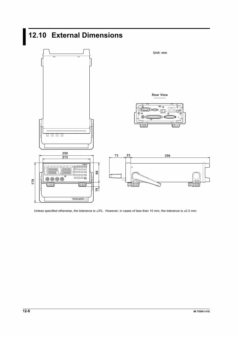
12-8 IM 755601-01E
12.10 External Dimensions
356
Rear View
2373250213
8819
179
Unit: mm
Unless specified otherwise, the tolerance is ±3%. However, in cases of less than 10 mm, the tolerance is ±0.3 mm.

Index
Index-1IM 755601-01E
Index
Index
GGET ..................................................................................... 9-4GTL ..................................................................................... 9-4
Hhandler interface ............................................. 1-3, 7-1, 10-18handshaking method ................................................... 8-4, 8-8header ................................................................................. 9-7HI LIMIT .............................................................................. 4-5HI LIMIT display .................................................................. 2-1HIGH SPEED ...................................................................... 4-8
IIFC ...................................................................................... 9-4initial settings ...................................................................... 1-7initial values, a list of ........................................................... 1-7initialize ....................................................... 6-7, 10-23, 10-34interface message ............................................................... 9-4INTERNAL ........................................................................ 4-11
Kkey test .............................................................................. 11-6
Llimit mode ................................................................ 4-1, 10-20limit value ........................................................ 4-5, 4-6, 10-20listener ................................................................................ 9-1LLO ..................................................................................... 9-4LO LIMIT ............................................................................. 4-5LO LIMIT display ................................................................. 2-1local ..................................................................................... 8-1LOCAL key .......................................................................... 8-1local lockout .................................................................... 10-16
Aabbreviated form ............................................................... 10-4absolute (R) mode .............................................................. 4-1address ............................................................................... 9-7addressable mode .............................................................. 9-7adjustment ............................................................ 11-7, 11-10
Bbar display ........................................................................... 2-4baud rate ..................................................................... 8-1, 8-8block data .......................................................................... 10-6block diagram ...................................................................... 1-1boolean ............................................................................. 10-6
Ccharacter data ................................................................... 10-6check level .......................................................................... 4-7check time ......................................................................... 12-4comparator function .................................................... 1-2, 4-5contact check .................................................................. 10-15contact check function ................................................ 1-2, 4-7
Ddata ................................................................................... 10-5data format .......................................................................... 8-8DCL ..................................................................................... 9-4deadlock ............................................................................ 10-2deviation (%) mode ............................................................. 4-1digital numbers and characters ........................................... 1-4
Eedge ................................................................................ 10-32EOM ............................................................................ 7-1, 7-5error code .............................................................. 10-30, 11-2error display ................................................................ 2-4, 5-1error message ................................................................... 11-2error queue ..................................................................... 10-40extended event enable register ....................................... 10-29extended event register ...................................... 10-29, 10-39EXTERNAL ....................................................................... 4-11external trigger input terminal ........................................... 4-10
Ffactory default settings ................................................ 1-7, 6-7FAST ................................................................................... 4-8fuse ................................................................................. 11-12
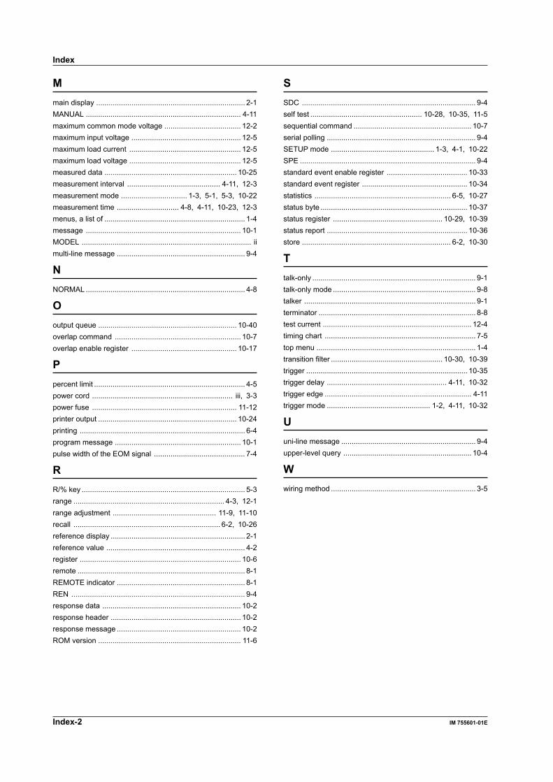
Index-2 IM 755601-01E
Index
Mmain display ........................................................................ 2-1MANUAL ........................................................................... 4-11maximum common mode voltage ..................................... 12-2maximum input voltage ..................................................... 12-5maximum load current ...................................................... 12-5maximum load voltage ...................................................... 12-5measured data ................................................................ 10-25measurement interval ............................................. 4-11, 12-3measurement mode ................................ 1-3, 5-1, 5-3, 10-22measurement time .............................. 4-8, 4-11, 10-23, 12-3menus, a list of .................................................................... 1-4message ........................................................................... 10-1MODEL .................................................................................. iimulti-line message .............................................................. 9-4
NNORMAL ............................................................................. 4-8
Ooutput queue ................................................................... 10-40overlap command ............................................................. 10-7overlap enable register ................................................... 10-17
Ppercent limit ......................................................................... 4-5power cord .................................................................... iii, 3-3power fuse ...................................................................... 11-12printer output ................................................................... 10-24printing ................................................................................ 6-4program message ............................................................. 10-1pulse width of the EOM signal ............................................ 7-4
RR/% key ............................................................................... 5-3range ......................................................................... 4-3, 12-1range adjustment .................................................. 11-9, 11-10recall ....................................................................... 6-2, 10-26reference display ................................................................. 2-1reference value ................................................................... 4-2register .............................................................................. 10-6remote ................................................................................. 8-1REMOTE indicator .............................................................. 8-1REN .................................................................................... 9-4response data ................................................................... 10-2response header ............................................................... 10-2response message ............................................................ 10-2ROM version ..................................................................... 11-6
SSDC .................................................................................... 9-4self test ...................................................... 10-28, 10-35, 11-5sequential command ......................................................... 10-7serial polling ........................................................................ 9-4SETUP mode .................................................. 1-3, 4-1, 10-22SPE ..................................................................................... 9-4standard event enable register ....................................... 10-33standard event register ................................................... 10-34statistics .................................................................. 6-5, 10-27status byte ....................................................................... 10-37status register ..................................................... 10-29, 10-39status report .................................................................... 10-36store ........................................................................ 6-2, 10-30
Ttalk-only ............................................................................... 9-1talk-only mode ..................................................................... 9-8talker ................................................................................... 9-1terminator ............................................................................ 8-8test current ........................................................................ 12-4timing chart ......................................................................... 7-5top menu ............................................................................. 1-4transition filter ...................................................... 10-30, 10-39trigger .............................................................................. 10-35trigger delay .......................................................... 4-11, 10-32trigger edge ....................................................................... 4-11trigger mode .................................................. 1-2, 4-11, 10-32
Uuni-line message ................................................................. 9-4upper-level query .............................................................. 10-4
Wwiring method ...................................................................... 3-5