Digital Front End (DFE) Training
21
Digital Front End (DFE) Training DFE Overview 1
Transcript of Digital Front End (DFE) Training
Digital Front End (DFE) Training
DFE Overview
1

AgendaHi h d D C S O i• High‐speed Data Converter Systems Overview
• DFE High‐level Overview• DFE Functional Block Diagramsg• DFE Features• DFE System Use Cases• DFE Configuration• DFE Configuration
2

High‐speed Data Converter System Overview (1)• Signals can be represented in the time domain or frequency domain.
• In order to describe the signal processing in a high‐speed data converter system on the following slides, it will be helpful to look at the signal in the frequency domain at several key places.
Time Domain:
Frequency Domain:
3

High‐speed Data Converter System Overview (2)• Processors handle data channels of interest at symbol rate.
i d/ i d i l
• The combined stream is sent across the JESD interface.
• Digital up/down conversion and combination up‐samples and moves the individual channels up or down in frequency and combines them into a higher bandwidth stream.
A l /RF i th bi d i l t RF hFrequency0 Hz
Transmitted/Received signal at wireless/wired medium
RF(i 2 4 GH )
1 2 n
0 Hz
Channel 1Freq
• Analog/RF processing moves the combined signal to RF so each channel ends up at the desired carrier frequency.
Channel Digital
(i.e. 2.4 GHz)
Analog / RF Up Conversion
0 Hz
Channel 2
Channel n
Freq
Freq 0 Hz Frequency
gUp/Down Conversion and Combination
1 2 n
0 Hz Frequency
1 2 n
JESD Interface
0 HzFreq
Individual channels of interest for symbol rate processing(i.e. 0 – 75MHz)
q yChannels of interest
Stream after channel combination
(i.e. 60 – 368 MHz)(Zero‐IF System)
q y
Stream at JESD interface(i.e. 60 – 368 MHz)
4Digital processing Analog processing
( y )

High‐speed Data Converter System Overview (3)i d/ i d i l
Frequency0 Hz
Transmitted/Received signal at wireless/wired medium
IF + RF(i 2 4 GH )
1 2 n
• Low‐IF systems add one stage.
• The combined stream is up‐converted to an Intermediate Frequency (IF) before going to RF.
0 Hz
Channel 1Freq
Stream Digital Up
(i.e. 2.4 GHz)
Channel Digital
Analog / RF Up Conversion
0 Hz Frequency0 Hz Frequency
0 Hz
Channel 2
Channel n
Freq
Freq
Stream Digital Up Conversion for Low‐IF
Systems
IF
1 2 n1 2 n
gUp/Down Conversion and Combination
q y
Stream at JESD interface(i.e. 122 – 368 MHz)
q y0 Hz
FreqChannels of interest
Individual channels of interest for symbol rate processing(i.e. 0 – 75MHz)
Stream after channel combination
(i.e. 60 – 368 MHz)(Low‐IF System)
5Analog processingDigital processing
( y )

DFE High‐level Overview
6
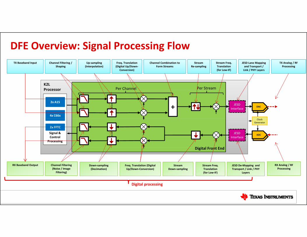
DFE Overview: Signal Processing Flow
K2LProcessor Per Channel Per Stream
TX Baseband Input Channel Filtering / Shaping
Up‐sampling (Interpolation)
Freq. Translation (Digital Up/Down‐
Conversion)
Channel Combination to Form Streams
StreamRe‐sampling
JESD Lane Mapping and Transport / Link / PHY Layers
TX Analog / RF Processing
Stream Freq. Translation(for Low‐IF)
DAC
Processor
DAC
Cl k
JESD Interface+
Per Channel
...4x C66x
2x A15
ADC
Di it l F t E d
ADC
Clock Generator
JESD Interface
...Signal & Control
Processing
2x FFTC
Digital Front End
RX Analog / RF Processing
Stream Freq. Translation(for Low‐IF)
StreamDown‐sampling
Freq. Translation (Digital Up/Down‐Conversion)
Down‐sampling(Decimation)
Channel Filtering (Noise / Image
Filtering)
RX Baseband Output JESD De‐Mapping and Transport / Link / PHY
Layers
Digital processing

DFE Functional Block Diagram

Transmit Path
9

Receive Path
10

Feedback PathJESD204B Interface
Color Legend
DPD/Capture Buffer not be available on all devices
Stream Processing Feedback
JESD SYSREF
(2) sets LVDSJESD SYNCOUT
JESD
DualJESD LaneParallelTx/Rx
DualJESD LaneParallel
Capture Buffer
Feed‐back
ParallelTx/Rx
11

DFE Features (1)
Key Features Capacity
Direct JESD204B connectivity with high speed data converters
• Four JESD204B TX and RX Serdes lanes, each supporting data rates up to 7.37Gbps• Two sets of JESD SYNC IN/OUT signals allow connection with up to two devices
simultaneously
Number of Streams (Antennas) • Up to 4 transmit, 4 receive and 2 feedback streams (each RX and TX stream can be real or complex)
Number of Channels • Four DDUCs (Digital Down/Up converters),each:• Supports up to 12 channels• Can be used for transmit or receive
Bandwidth Supported • 368 MHz of instantaneous bandwidth• 150 MHz of occupied (processed) bandwidth• Fixed filters at the stream level provide 90% passband and 90dB stopband rejection
12

DFE Features (2)Transmit processing Receive processing
• Channel processing: Filtering (programmable FIR filter) , fractional re‐sampling, frequency translation and summation (channel to stream conversion)
• Channel processing: Frequency translation, fractional re‐sampling and filtering (programmable FIR filter)
summation (channel to stream conversion)
• Stream processing: Fractional re‐sampling, frequency translation (for low‐IF support), JESD204B mapping and transport
• Stream processing: JESD204B transport and de‐mapping, frequency translation (for low‐IF support) and decimation
h l f h l f• Channel power meters for power monitoring • Channel power meters for power monitoring
• Crest Factor Reduction (CFR)* and Digital Pre‐Distortion (DPD)*
• Two feedback streams for TX monitoring (to supportDPD*) or extra RX capacity
TX i l i b bili RX i l i b bili• TX signal processing bypass capability • RX signal processing bypass capability
*Supported on K2L versions targeted towards wireless small cell base‐station markets
13

DFE System Use Cases
Typical DFE system use‐case scenarios include:• Discrete ADC and DACI t t d RF T i• Integrated RF Transceiver
• DFE Signal processing bypass
14

Use Cases: Discrete ADC and DAC (1)
15

Use Cases: Discrete ADC and DAC (2)S d ADC l• Supported ADC classes:– RF Sampling: RF input/Complex output or Real input/Real output– Dual Real ADC (old technology): Complex input from IQ demodulator, Complex outputoutput
– IF Sampling (Non zero‐IF systems): Complex IF input, Complex output
S t d DAC l• Supported DAC classes:– RF Sampling: Complex input, RF output (usually real)– Dual Real DAC (old technology): Complex input, Complex output at Zero‐IF (for input to IQ modulator)input to IQ modulator)
– IF Sampling: Complex input, IF output (Real or Complex)– Single Real DAC: Real Input, Complex IF output
16

Use Cases: Integrated RF Transceiver
17

Use Cases: DFE Signal Processing Bypass
18

DFE Configuration• The integrated DFE is configured using the RFSDK software provided by TI.
• RFSDK:– Runs on ARM/Linux/– Uses TI‐provided MCSDK Linux Dev Kit drivers to communicate with the hardware– Contains a set of pre‐built radio configurations selectable by the customerP id t f API t t t/ t ti d ll h i d i t– Provides set of APIs to start/stop operation and allow changing dynamic parameters (gain, etc.) during operation
– Web server‐based graphical interface for control and data visualization• Data converters can also be configured from K2L device via I/O interfaces like SPI.
19

RFSDK ArchitectureARM
• RFSDK Radio Tools provide the top‐level control interface.
• RFSDK Service performs actual
Radio Tools
ARM SW
DPDDFE
Web Server
IQNRFSDKServicep
control and configuration.
• Playback and Web Server provide RFSDK debug and test
IQNLLD
QMSSLLD
CPPILLD
DFELLD
Service
p gcapabilities.
ADC /DAC /DFE
JESDPlayback Config
Si l P i / N2 ‐A
ID
DSPs
AFESignal Processing /Real‐time Software IQ
N
RFSDK
20
MCSDK RFSDK CustomerRFSDK Test/DebugLegend:

Get Started Today
Learn more:• 66AK2Lx SoC Overview• TI Design Page• 66AK2L06 Product Folder
/• SYS/BIOS and Linux‐MCSDK for Keystone‐II Devices
21