Digital Audio - Technical Writing Class Paper - OCR Reformat
50
AN ANALYSIS OF THE ADVANTAGES, DISADVANTAGES, AND STANDARDIZATION OF DIGITAL AUDIO for Professor Eugene O. Young Technical writing Instructor Texas A&M University College Station, Texas by Paul Robert Teich Student Computing Science April 26, 1982
-
Upload
paul-teich -
Category
Technology
-
view
317 -
download
0
Transcript of Digital Audio - Technical Writing Class Paper - OCR Reformat
AN ANALYSIS OF THE
ADVANTAGES, DISADVANTAGES, AND STANDARDIZATION
OF
DIGITAL AUDIO
for
Professor Eugene O. Young
Technical writing Instructor
Texas A&M University
College Station, Texas
by
Paul Robert Teich
Student
Computing Science
April 26, 1982

i
LETTER OF TRANSMITTAL
406 C Manuel Dr.
College Station, Texas 77840
April 26, 1982
Dr. Eugene O. Young
217-D Academic and Agency Building
Texas A&M University
College Station, Texas 77843
Dear Dr. Young:
I have completed the major report for English 301 and am submitting it for
grading. The title of my report is: “An Analysis of the Advantages,
Disadvantages, and Standardization of Digital Audio.” I am a computing science
major, and my hobby is high fidelity sound reproduction. The research I did for
this paper laid the groundwork for my research project this summer, which will be
on replicating human speech inflections and accent with a digital speech
synthesizer.
The field of digital audio is very young, even when compared with the age
of digital computer technology. I believe, though, that in the next decade,
digital audio will take over a major portion of the consumer audio market. This
report is written to audiophiles who have heard about digital audio products, but
have had no exposure to literature on them. There are no books devoted to digital
audio and most articles are very technical, requiring quite a bit of knowledge
about digital computers. To get a fairly extensive knowledge of digital audio
requires days of looking for sources and reading. Some of the information was not
directly available at all, but was the result of written inquiries to various
manufacturers. I have not yet found a more comprehensive report on digital audio
than mine.
Thank you for your advice on using note cards and on revision. This is the
largest paper I have ever completed, and I am going to include it, along with my
summer research on my resume. If you have any questions about my report, please
call me at 693-5560.
Sincerely,
Paul R. Teich

ii
Table of Contents
LETTER OF TRANSMITTAL ...................................................... i
LIST OF ILLUSTRATIONS ..................................................... iv
LIST OF TABLES ............................................................ iv
ABSTRACT .................................................................. v
INTRODUCTION............................................................... 1
THE DIGITAL AUDIO PROCESS .................................................. 2
Digital Audio Recording .................................................. 2
Filtering of analog input signal ....................................... 2
Analog-to-digital conversion of signal ................................. 3
Digital Audio Playback ................................................... 6
Pickup of digital information from storage media........................ 6
Digital-to-analog conversion of binary code ............................ 6
Filtering of output signal ............................................. 7
Summary .................................................................. 7
DISADVANTAGES OF THE DIGITAL AUDIO PROCESS ................................. 7
Aliasing Distortion ...................................................... 8
Quantization Noise ...................................................... 10
ADVANTAGES OF THE DIGITAL AUDIO PROCESS ................................... 13
Specifications .......................................................... 13
Frequency response .................................................... 13
Channel separation .................................................... 13
Total harmonic distortion ............................................. 14
Wow and flutter ....................................................... 14
Signal-to-noise ratio ................................................. 14
Dynamic range ......................................................... 14
Error Detection ......................................................... 16
Parity ................................................................ 16
Cyclic redundancy check code (CREE) ................................... 17
Error Concealment ....................................................... 17
Error Correction ........................................................ 18
Other Advantages ........................................................ 20

iii
PROBLEMS WITH STANDARDIZING THE CONSUMER DIGITAL AUDIO FIELD .............. 21
Recording Formats ....................................................... 21
Sampling rate ......................................................... 22
Quantizing bits ....................................................... 24
Non-audio information ................................................. 26
Total format .......................................................... 28
Storage/Playback Systems ................................................ 28
Tape .................................................................. 29
Disc .................................................................. 29
SELECTED DIGITAL AUDIO SYSTEMS ............................................ 32
Technics by Matsushita .................................................. 32
JVC ..................................................................... 33
Sony .................................................................... 34
PCM-F1 ................................................................ 34
DAD-1X ................................................................ 34
FUTURE OF DIGITAL AUDIO ................................................... 35
Digital Audio Discs ..................................................... 35
Advantages ............................................................ 35
Disadvantages ......................................................... 37
Support ............................................................... 37
Digital Audio Today ..................................................... 38
CONCLUSION................................................................ 39
APPENDIX ................................................................. 41
GLOSSARY OF TERMINOLOGY ................................................. 41
BIBLIOGRAPHY ............................................................ 43
iv
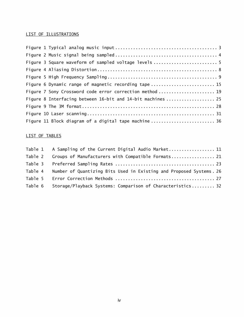
LIST OF ILLUSTRATIONS
Figure 1 Typical analog music input ........................................ 3
Figure 2 Music signal being sampled ........................................ 4
Figure 3 Square waveform of sampled voltage levels ......................... 5
Figure 4 Aliasing Distortion ............................................... 8
Figure 5 High Frequency Sampling ........................................... 9
Figure 6 Dynamic range of magnetic recording tape ......................... 15
Figure 7 Sony Crossword code error correction method ...................... 19
Figure 8 Interfacing between 16-bit and 14-bit machines ................... 25
Figure 9 The 3M format .................................................... 28
Figure 10 Laser scanning .................................................. 31
Figure 11 Block diagram of a digital tape machine ......................... 36
LIST OF TABLES
Table 1 A Sampling of the Current Digital Audio Market .................. 11
Table 2 Groups of Manufacturers with Compatible Formats ................. 21
Table 3 Preferred Sampling Rates ....................................... 23
Table 4 Number of Quantizing Bits Used in Existing and Proposed Systems . 26
Table 5 Error Correction Methods ....................................... 27
Table 6 Storage/Playback Systems: Comparison of Characteristics ......... 32
v
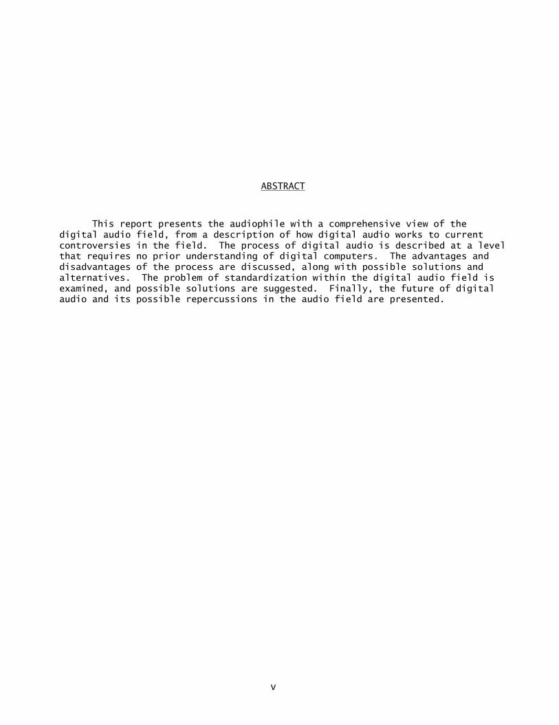
ABSTRACT
This report presents the audiophile with a comprehensive view of the
digital audio field, from a description of how digital audio works to current
controversies in the field. The process of digital audio is described at a level
that requires no prior understanding of digital computers. The advantages and
disadvantages of the process are discussed, along with possible solutions and
alternatives. The problem of standardization within the digital audio field is
examined, and possible solutions are suggested. Finally, the future of digital
audio and its possible repercussions in the audio field are presented.

1
INTRODUCTION
The “Computer Revolution,” started in the mid-1960s, has been gradually
edging into the audio field for years. It started with digital FM tuning
circuits and electronically controlled turntable motors, which used quartz phase-
locked loop (PLL) circuits. In the last three or four years, microprocessor
control has been an integral part of tape decks, pre-amplifiers, and such; and it
recently has been added to equalizers and remote control devices. However, the
nature of recorded sound had not changed. Microprocessors could help get the best
possible analog recordings, but could not improve on the actual method of
recording.
Analog recording, since its invention by Thomas Edison, translates music to
an electronic equivalent. The amplitude of a voltage or current is made
proportional to the loudness of the music, and the frequency matches that of the
music on a one-to-one ratio (4:225). Digital recording takes an analog music
signal and converts it into a computer readable code. The advantage of the
digital process is that the music can be measured for computer coding with much
greater precision than the magnetic field strength of a tape can be measured
(1:132). This means that the computer code can be recorded on tape or disk; and,
when it is played back, the music is not dependent on the physical
characteristics of the tape for its reproduction.
This report will present a detailed description of the digital audio
process, as well as its advantages and disadvantages. The problem of
standardization in the field of consumer digital audio equipment will be
discussed, and some sample systems will be examined. This report assumes that
the reader is well acquainted with most aspects of high fidelity sound systems,
including specifications, measurements and technical terminology. Some working
definitions will be included in the Appendix at the end of the report.

2
Most of the Sources for this paper are from the Journal of the Audio
Engineering Society and Stereo Review Magazine, due to the fact that digital
audio is a very young field with no books published as yet. The rest of the
references are from other trade journals, informational brochures, and a passing
reference to digital audio as a future development in a recent book. Few sources
are over five pages long.
THE DIGITAL AUDIO PROCESS
Digital audio can be divided into two separate processes: digital recording
and playback. The process of digital recording consists of: (1) Filtering of the
analog input signal, (2) analog-to-digital conversion of the signal, and (3)
transfer of the digital information to the recording media. The steps involved
in digital playback are: (1) Pickup of the digital information from the recording
media, (2) digital-to-analog conversion of the binary code, and (3) filtering of
the output signal.
Digital Audio Recording
Filtering of analog input signal. First, an analog input signal, usually
from a pre-amplifier (8:560), is routed through a very sharp-cutoff, high-
frequency-cut filter. This filter, called an anti-aliasing filter, removes all
frequencies above the highest frequency to be reproduced (20:64) (see Figure 1).
In most systems, this frequency is 20 kHz.

3
Figure 1 (a) Typical analog music input from a pre-amplifier, containing very
high frequency noise (20:63).
(b) Music signal after anti-alias filtering (20:64).
Analog-to-digital conversion of signal. The voltage of the filtered analog
signal is next measured at very small, constant intervals of time. The frequency
of this sampling is determined from a mathematical model, which states that the
signal must be sampled at least at twice the highest frequency to be reproduced.
Common sampling rates are between 44 kHz and 5l kHz (23:17). To measure the
voltage of the signal at each time interval, a "sample-and-hold” circuit is used.
This circuit samples the voltage of the signal at the beginning of a time
interval, and then holds its own voltage equal to the sampled value for the

4
duration of the interval (see Figure 2). It repeats this process for each
interval to be measured (20:64).
Figure 2 Music signal being sampled (20:64).
The output of the sample-and-hold circuit is a series of voltage levels in
the form of a square wave (see Figure 3a). The voltage levels are now
individually compared to a set of reference voltage levels and they are then
translated, using an analog-to-digital (A/D) converter, to binary numbers
(34:65). Binary is a number system that uses combinations of ones and zeroes,
called "bits,” to represent numbers. The output of the converter is a string of
bits, called “binary code”, which is an accurate representation of the sample-
and-hold circuit output (see Figure 3c). The process of changing the samples
from analog to binary form is known as "quantization" (2324).

5
Figure 3 (a) Square waveform of sampled voltage levels (20:64).
(b) Waveform after being rounded off to the reference levels (20:65).
(c) Binary code generated by analog-to-digital converter.
The last step in the analog-to-digital conversion sequence is the encoding
of the binary code. This procedure inserts timing and error correction
information, in binary form, into the code. It also can merge two separate
channels for stereo. The output of the encoding step is all of the digital
information necessary for the reconstruction of the analog input signal (1:132).
The final process is the actual recording of the digital information onto
tape. This is done by translating the bits of the binary code into

6
electromagnetic pulses, which are recorded on tape in the same way an analog
signal would be recorded. The tape may now be copied, transferred onto master
audio discs, or transferred to other storage media.
Digital Audio Playback
Pickup of digital information from storage media. First, the digital
information is translated from storage media back into the string of digital
information needed to reconstruct the original analog signal (20:65).
Digital-to-analog conversion of binary code. The first process that the
digital information encounters is the removal of the timing and error correction
information. The error correction information is used to restore the parts of
the binary code that were not picked up properly, due to flaws in the storage
media or pickup mechanism. The timing information is used to control how fast
the digital information is being picked up from the storage media. As the error
correcting is finished, the binary code is put into a waiting area, called a
buffer, for temporary storage. The amount of material the buffer can hold is
limited, however, so the timing information is used to control the pickup
mechanism. For example, if digital information is being picked up and filling
the buffer too fast or too slowly, the timing information corrects the speed
deviation (20:65).
As the binary code is put into the back of the buffer, the codes for the
individual voltage levels are taken from the front. Then, they are removed at a
rate equal to the original sampling frequency which is used in the recording
process. As they are removed, they are translated, using a digital-to-analog
(D/A) converter, back into their corresponding voltage levels. The output of the
digital-to-analog conversion is a series of voltages in the form of a square
waveform. This replicates the output of the sample-and-hold circuit, with the

7
small differences due to the rounding off process during quantization of the
original waveform (20:65).
Filtering of output signal. The final stage of this process is the
changing of the square waveform into a constantly varying analog signal. This is
accomplished by an "output-smoothing" filter, which, as the anti-aliasing filter
did, removes all frequencies above the highest frequency to be reproduced. The
effect is the smoothing of the square waveform into an almost exact replica of
the input to the digital audio recording process (20:65).
Summary
A music signal to be recorded first encounters the anti-aliasing filter.
Next, the signal is sampled, and the samples are rounded off. Then, the samples
are quantized, encoded and, finally, transferred to the recording media. To
restore the music to analog form, the digital information is picked up from the
recording. It is then decoded and sent to the digital-to-analog converter. The
signal from the D/A converter is sent through an output-smoothing filter, which
results in a replica of the original music signal.
DISADVANTAGES OF THE DIGITAL AUDIO PROCESS
There are three disadvantages associated with the process of digital audio.
Aliasing distortion and quantizing noise are the two main problems. Both result
in distortion in a digital audio system, and neither of these forms of distortion
are found in analog systems. While aliasing distortion is a correctable problem,
quantizing noise is rooted in the theoretical capabilities of digital audio
(20:65-6). The third disadvantage is the cost of a digital audio system. This is
a temporary condition, however, as technological advances are already lowering
the cost of digital audio equipment (14:57).

8
Aliasing Distortion
As described earlier, there is a mathematical relationship which states
that the sampling frequency of the music must be at least twice the highest
frequency to be sampled (see Figure 4a). This assures that both the positive and
the negative halves of even the highest frequency are sampled (see Figure 4b)
(16:57).
Figure 4 (a) Comparison of properly filtered system with improperly filtered
system (3:511).
(b) 20 kHz since wave (solid line) being sampled (dotted line) at 44
kHz (16:59).

9
If a frequency above half the sampling rate is sampled, it results in an
incorrect voltage for that sample. During playback, the incorrect voltage will
show up as a lower frequency distortion (see Figure 5). This distortion is
called "aliasing" distortion, because the low frequency signal generated is a
false representation, or "alias,” of the high frequency input (20:64). Aliasing
distortion products are not harmonically related to the music, and so they are
very noticeable (3:510). The effects of aliasing distortion also include the
downgrading of the signal-to-noise ratio of the recording (23:5).
Figure 5 (a) High frequency is sampled at low point.
(b) High frequency is sampled at high point.
(c) Filtered curve is sampled.
To minimize aliasing distortion, the sampling rate must be at least twice
the highest frequency sought. Equally as important is the filtering of the input
to remove any unsought higher frequencies. This is the purpose of the anti-
aliasing filter used in the digital recording process.

10
Quantization Noise
During the quantizing step of digital recording, the sampled voltage levels
are rounded off to the nearest reference level. The reference levels are a part
of the analog-to-digital converter, and are used in the same way that the
markings on a ruler are used to approximate a value that could have very many
decimal places (3 inches compared to 3.002 inches) (20:65). "There is always a
slight error between the original signal level and the quantized value.” (23:5).
These errors are heard as noise, and are called “quantizing noise.”
To minimize quantizing noise, more closely spaced reference levels must be
used. However, this introduces two other problems. First, the finer the spacing
between reference levels, the larger the binary number needed to represent the
levels; therefore, more space is used to record the number. The more space each
number takes up, the less music fits onto a tape or disc. The second problem is
that, as the spacing gets closer, it becomes harder for the analog-to-digital
converter to tell the difference between adjacent levels (20:65). This problem
is rooted in the present limits of integrated electronic circuitry technology.
To combat these problems, it is necessary to compromise accuracy for space and
electronic considerations. How much compromise depends on the whims of the
digital audio system designers. However, when better analog-to-digital
converters and faster, cheaper, computer memory become available, there will be
no need for a tradeoff.
There are two very audible subdivisions of quantizing noise. The first is
called “granulation noise.” As the signal gets weaker (near the bottom of the
system's dynamic range), the rounding off process alters a larger percent of the
input signal. This can add a harsh, gritty distortion to the music signal. "The
subjective effect of this noise is much more unpleasant than ordinary tape hiss.”
11
To correct granulation noise, many digital recorders add a low level hiss to the
music. This changes the granulation noise to a more benign form of hiss (16:58).
The other problem is that when a signal is recorded that is larger than the
highest reference level, it is rounded to the highest reference level. The
analog recording equivalent of this is clipping, but the effect is much more
noticeable in digital audio. The solution to digital clipping is, while
recording the music, to set the recording level a few decibels lower, although
this also decreases the dynamic range of the recording (16:58).
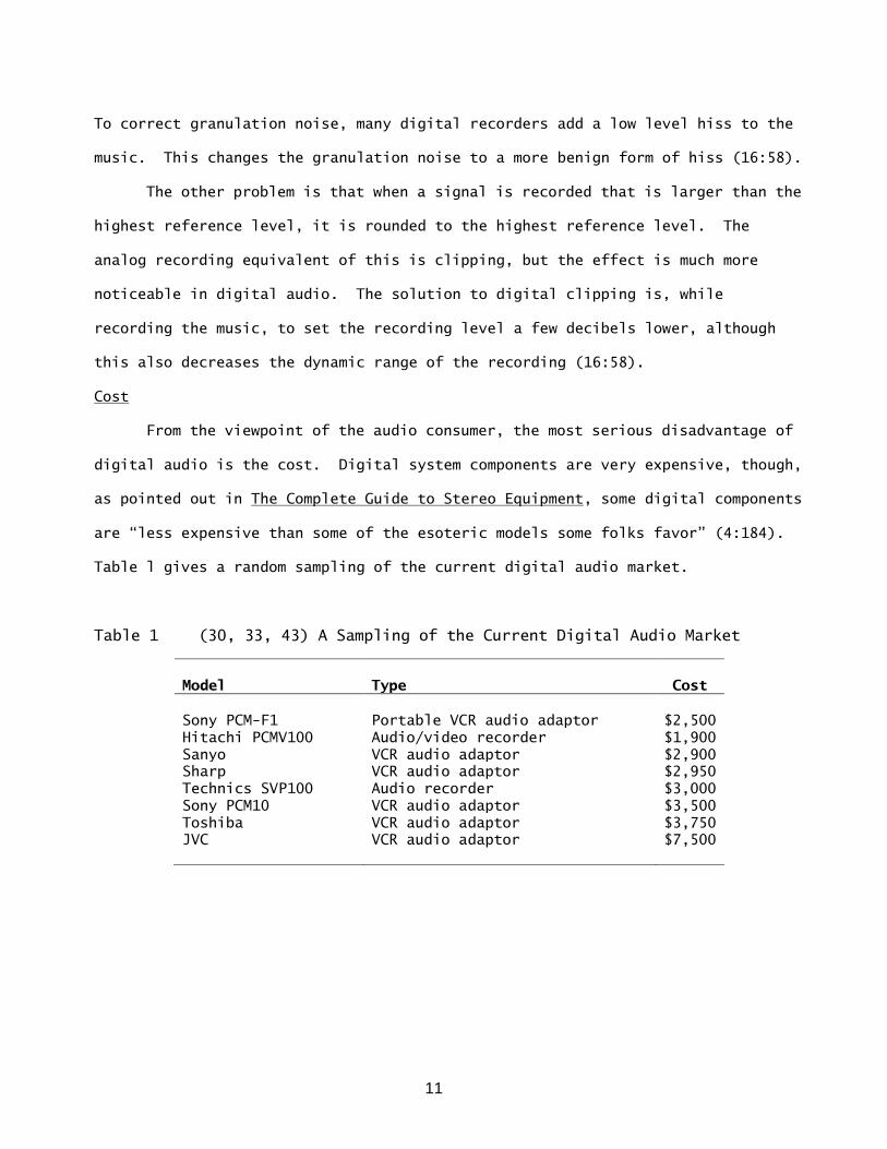
Cost
From the viewpoint of the audio consumer, the most serious disadvantage of
digital audio is the cost. Digital system components are very expensive, though,
as pointed out in The Complete Guide to Stereo Equipment, some digital components
are “less expensive than some of the esoteric models some folks favor” (4:184).
Table l gives a random sampling of the current digital audio market.
Table 1 (30, 33, 43) A Sampling of the Current Digital Audio Market
Model
Type
Cost
Sony PCM-F1 Portable VCR audio adaptor $2,500
Hitachi PCMV100 Audio/video recorder $1,900
Sanyo VCR audio adaptor $2,900
Sharp VCR audio adaptor $2,950
Technics SVP100 Audio recorder $3,000
Sony PCM10 VCR audio adaptor $3,500
Toshiba VCR audio adaptor $3,750
JVC
VCR audio adaptor $7,500

12
There are several reasons why digital audio reproduction is so expensive,
all are by-products of digital computer technology. First, though not an
equipment cost, is the price of video cassette recorder (VCR) tape. VCR tape is
needed, because the frequency of the electronic pulse representing the binary
code is typically measured in megahertz (MHz). In the case of the Sony PCM-10,
the sampling frequency (44.056 kHz) is multiplied by 14 bits per sample and by
two channels (for stereo reproduction) to obtain 1.234 MHz with error correction
and synchronization, the resulting frequency may be as high as 2.643 MHz.
Standard audio cassette tapes cannot record such high frequencies, which is why
VCR tape is used (23:l0). Even when ordered from a warehouse supplier, VCR tape
prices range from $12.00 to above $17.00 per tape (12:2).
The reasons why digital audio equipment, itself, is so expensive deal with
current computer and integrated circuitry technology. To reduce distortion
caused by the elements in this circuitry (as happens in all audio systems), high-
speed, high-precision circuit elements are needed (23:5). In digital audio
systems, the sample-and-hold, analog-to-digital, synchronizing, and error
correction circuitry are all implemented using integrated circuitry (see
Appendix).
Integrated circuits of the complexity needed for audio applications are
very expensive to produce. Only the larger audio electronics corporations, such
as Sony, have the resources needed to design and produce their own integrated
circuitry (14:57). Other electronics companies, outside of the audio field, have
produced chips to sell to audio manufacturers. An example of an integrated
circuit produced for audio applications is the Burr-Brown Corporation's PCM75
analog-to-digital converter. There are several models, ranging from $198 to $249,
depending on the speed and distortion of each model (19:1).

13
ADVANTAGES OF THE DIGITAL AUDIO PROCESS
There are many more advantages to the digital audio process than
disadvantages. The specifications of a digital system's ability to reproduce
sound are much better than analog system specifications. Digital systems make
use of signal error detection, concealment and correction, while analog systems
do not. In addition, copying digital recordings does not degrade the sound.
There is no print-through on digital tapes; and on audio discs (analogous to
records), any wear that may occur will not affect the music.
Specifications
The specifications used to describe how well a digital audio system
reproduces music are the same as used in analog audio. The major categories are:
(1) frequency response, (2) channel separation, (3) total harmonic distortion,
(4) wow and flutter, (5) signal-to-noise ratio, and (6) dynamic range.
Frequency response. The frequency response of digital systems is limited
only in the high-frequency response. This is because of the anti-aliasing filter.
However, if the proper filter and sampling rate are used, the high-frequency
response can be extended beyond the range of human hearing. The frequency
response of a digital recording is also exceptionally flat, displaying none of
the dips, peaks and roll offs associated with analog readings. It is not
uncommon for digital recordings to display a frequency response of 0 - 20 kHz ± 1
dB (17:623).
Channel separation. When recording music digitally, the two (stereo)
channels are sampled separately. After they are converted to binary, they are
merged, giving two values (for left and right channels) for each time interval,
and then are encoded. Upon playback, the binary code is decoded, and the two
14
channels are separated and sent to separate buffers (10:65). This process
insures that the two channels do not intermix, and it gives digital audio a
channel separation specification equal to its dynamic range. For most digital
audio systems, this is equal to or greater than 90 dB (17:623). Crosstalk is
also eliminated.
Total harmonic distortion. In a digital system, harmonic distortions are
produced "only by the electronic circuits for coding and decoding” (28:520).
Given the state of modern digital technology, in most digital systems, the total
harmonic distortion can be kept equal to or below 0.05% (17:623).
Wow and flutter. During the digital-to-analog translation of digital
playback, the individual voltage levels are released from the buffer at
essentially unvarying time intervals. A crystal oscillator timing mechanism,
similar to those used in electronic watches and phase-locked turntables,
implements this (8:66). Wow and flutter is virtually eliminated from digital
systems by this process. If it does occur in greater than “unmeasurably small”
quantities, something is drastically wrong (20:65).
Signal-to-noise ratio. The signal-to-noise ratio (S/N ratio) of a system is
basically attributable to the mechanical limitations of the recording media. The
noise level in a digital recording, likened to tape hiss and surface noise in
analog recordings, is at much lower level and consists mainly of granulation
noise. There are no mechanical sources of noise in a digital system; so, for a
typical digital system, the S/N ratio should be equal to or greater than 90 dB
(again, approximating the value of the dynamic range).
Dynamic range. The most noticeable difference in the sound quality of
digital systems is in the dynamic range captured by digital recordings. In
analog recordings, very soft sounds are often buried below the noise level of the
storage media (tape hiss or record surface noise), while very loud sounds cannot

15
be recorded faithfully. Loud sounds may saturate the tape or cause the wiggles
in record grooves to overrun adjacent grooves (10:63). As a result, music to be
stored on records or tape must be "compressed”. Compression makes soft sounds
louder, and loud sounds softer. While this enables the entire musical selection
to fit onto the tape or record, "It detracts from the lifelike quality of musical
reproduction during playback” (4:225). The music on records and tapes usually
has a dynamic range of under 65 dB, compared to orchestra music, which has a
dynamic range of 85 to 95 dB (10:63) (see Figure 6).
Figure 6 Dynamic range of magnetic recording tape is approximately 60 dB, while
orchestra music has a range of 85 to 95 dB (10:63).
Because the electromagnetic pulses representing the binary code on the
magnetic tape (or the dots on the audio discs) are just a representation of the
sound, the level that they are recorded at is not important. On tape, a level
well above the residual tape hiss and well below the saturation level can be
chosen. The level of the pulses remains constant and, thus, eliminates the
disadvantages of recording analog music on tape (24:10).

16
The accuracy of digital audio techniques has been summed up by E. Brad
Meyer, of Point One Audio: "Digital sound will contain none of the frequency-
response errors, distortion, noise, flutter, and so on that are inherent in even
the best analog recording and reproducing systems" (16:56).
Error Detection
Even in the best digital systems, there will be mechanical causes for
dropouts or errors in reading the recorded music during playback (2315). These
situations, such as a scratch in a digital disc or a tape dropout, can be
disastrous in a digital system. With some types of encoding, a dropout causes a
burst of noise at the maximum possible output level on the machine. Clearly,
some form of error detection, common in computer software packages, is needed.
In fact, computer data error detection is entirely applicable to digital audio
(16:58). There are numerous error detection systems; however, only two shall be
mentioned here.
Parity. As stated earlier, binary code is a string of ones and zeroes
(bits). The binary code can be divided into groups of bits, which are called
"words,” of arbitrary length. Each word represents the level of one sampling of
the sound. All ones in a word then are counted. If the total is odd, a one is
inserted into the binary code immediately after the last bit in the word; if the
total is even, a zero is inserted in the same position. This last number is
called the parity bit. When the playback device reads the binary code from tape
or disc, it re-counts the ones in each word, comparing the results (odd or even)
to the parity bit shown. If these do not match, then an error has been detected.
Unfortunately, the parity procedure does not detect an even number of
errors within the same word, because such an error leaves the count equal to the
parity bit (even + even = even; odd + even = odd). This gives parity a 50%
17
chance of detecting an error. The single-parity-bit method is, at best, a
rudimentary means of error detection (2316).
Cyclic redundancy check code (CREE). CRCC is a method used by Sony
Corporation to provide error detection in their digital systems. It can use any
number of parity bits for each word. If the number of parity bits is "n”, then
the probability of an error being detected is 1 minus 2-n
. If "n" is 16 (as in
the Sony PCM-1600), the probability of error detection is 1 minus 2-16
= .999985
(99.9985%). This is an almost perfect error detection capability. (This
equation also describes one bit parity 1 minus 2-1
=1 minus .5 = .5). (23:6).
Error detection is only the first step in managing errors in digital
systems. Once an error has been detected, something must be done about it.
Error Concealment
To prevent the errors from affecting the quality of the sound, various
methods of concealing the error exist. There are three typical methods of error
concealment:
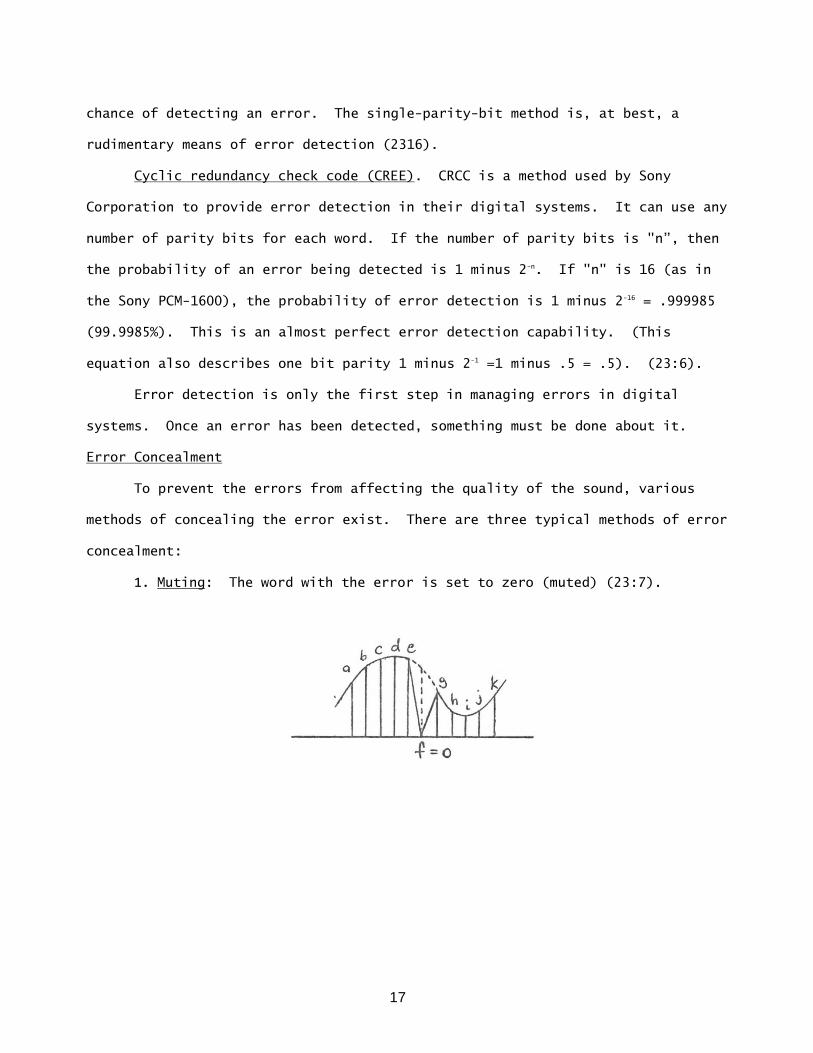
1. Muting: The word with the error is set to zero (muted) (23:7).

18
2. Previous word holding: The value of the word before the error is
substituted for the error (23:7).
3. Linear interpolation: The average of the two words immediately before
and after the error is substituted for the error. This is the most
accurate method of error concealment, but it assumes that the words on
either side of the error are not themselves erroneous (23:7).
Though error concealment is a great improvement over playing music with
errors in it, it is possible to go even further in retaining the quality of the
music.
Error Correction
“An error correction code not only detects the code errors but also
perfectly corrects them.” To do this, it is necessary to find out where and how
the errors have occurred. The code required to do this is very complex. To
explain how it works, a simplified description of Sony's Crossword Code is
examined in Figure 7 (23:7).
19
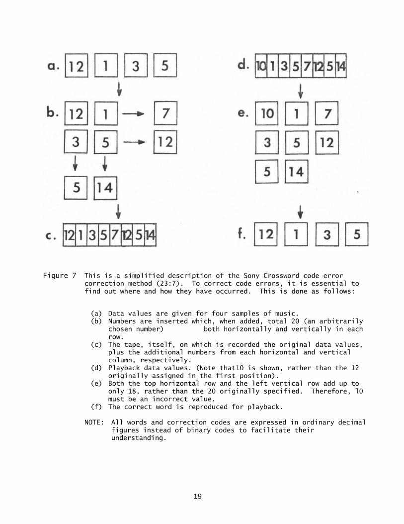
Figure 7 This is a simplified description of the Sony Crossword code error
correction method (23:7). To correct code errors, it is essential to
find out where and how they have occurred. This is done as follows:
(a) Data values are given for four samples of music.
(b) Numbers are inserted which, when added, total 20 (an arbitrarily
chosen number) both horizontally and vertically in each
row.
(c) The tape, itself, on which is recorded the original data values,
plus the additional numbers from each horizontal and vertical
column, respectively.
(d) Playback data values. (Note that10 is shown, rather than the 12
originally assigned in the first position).
(e) Both the top horizontal row and the left vertical row add up to
only 18, rather than the 20 originally specified. Therefore, l0
must be an incorrect value.
(f) The correct word is reproduced for playback.
NOTE: All words and correction codes are expressed in ordinary decimal
figures instead of binary codes to facilitate their
understanding.

20
Another Sony method, the cross-interleave rectification code (CIRC) can
fully correct code errors of up to 4000 bits (for a length of 2.5 mm on a digital
audio disc (27:66). This is remarkable, for a scratch that large on a
conventional record would not only destroy the musical passage, it would make the
record unplayable.
Other Advantages
There are several more advantages to digital audio; however, all of them
are by-products of the digital audio technology behind the specifications and
error-resolving techniques. Some of these are:
1. The elimination of print-through on the recordings. This is related to
the code being tape-recorded at any chosen level above the tape hiss
and below the saturation level of the tape (28:520).
2. The possibility of adding any number of alternate channels. Each
channel would still be totally separate from the others. This
suggests the possibility of bringing back quadrophonic sound or of
recording different instruments or vocals on different channels. A
user could turn the vocals off and sing along with no disturbance.
Similarly, a musician could blank out his particular instrument on the
recording and play along (29:512). This also raises the possibility
of recording comments, engineering notes (as to equalization,
microphone and speaker placement, etc.), and other non-music
information on a separate channel (29:512).
3. The possibility of mass producing tapes and audio discs with
definitely superior musical reproduction (as compared to records and
tapes currently on the market) (4:184) for a much lower cost than
today's recordings (16:56).

21
4. ". . . copies can be made from one digital machine to another without
the loss in quality that occurs with conventional recorders . . . an
exact duplicate of the signal that emerged from the recording console
at the original session" (16:58). This is because the binary code is
being recorded -- not the music.
PROBLEMS WITH STANDARDIZING THE CONSUMER DIGITAL AUDIO FIELD
Recording Formats
The standardization of recording formats is the most important issue
deciding the future of digital audio. Without standardization, the equipment
produced by one manufacturer will not directly be able to play the recordings
produced by another. The consumer would have to buy a format converter to do so;
and these, currently comprised mostly of integrated circuitry, would cost
hundreds of dollars. Digital audio is already a costly addition to a sound
system. Having to buy a converter for each format to be played would convince
most consumers that digital audio is not worth the cost. Table 2 shows which
manufacturers have equipment compatible with other manufacturers.
Table 2 (27) Groups of Manufacturers with Compatible Formats
1 2 3 4
U.S. Pioneer Philips Compact JVC Mitsubishi
Magnavox Built MCA Sony Compact
Philips
Sony Long Play

22
The recording format is a combination of sampling rate, quantization, and
non-audio information (error correction and synchronization). The only standards
set by industry for digital audio are from the electronics industry association
of Japan (EIAJ). The EIAJ standard STC-007, labeled "Consumer Use PCM Encoder-
Decoder”, sets three standards. First, it sets the number of bits used to
represent one sampling (the number of “quantizing bits”) to 14 bits. Second, it
sets the sampling rate to 44,056 Hz. Third, though it does not define what type
of error detection is required or what the decoding stage of the playback device
should do if it encounters an uncorrectable error, the standard requires that
some form of error correction be used (21:20). Though these are the first
industry standards in digital audio, they apply only to consumer equipment (not
professional equipment), and they have little influence over U.S. or other
overseas manufacturers. Without standardization of recording formats, it is
difficult (at best) to transfer a recording from one format to another (28:520).
Each part of the digital format will be examined here to provide the reader with
an idea of the scope of the standardization problem.
Sampling rate. The sampling rate has been the most widely differing factor
of the digital industry. Because most high-fidelity applications require at
least a frequency of 20 kHz, most of the sampling frequencies are above 40 kHz.
However, because the European Broadcast Union (EBU) and satellite communications
networks operate at 32 kHz, some manufacturers are considering this or some other
compatible frequency (17:621). Table 3 shows a list of audio industry leaders
and their preferred sampling rates.

23
Table 3 (3, 9, 17) Preferred Sampling Rates
Organization
Sample
Rate
Remarks
Ampex 50 kHz Absolute synchronization with
standard video film frame rates
Audio Engineering
Society (AES)
50.4 kHz High quality studio work
44.1 kHz Other studio applications
32 kHz Broadcasting applications
European Broadcasting
Union (EBU) 48 kHz Easy conversion to 32 kHz
SMPTE Video Study
Group 60 kHz
Integer samples of audio data for
frame
JVC 47.25 kHz Audio High Density (AHD) Systems
Sony/Philips 44.1 kHz Compact Audio Disc (CAD) Systems
Telefunken 48.0 kHz Mini Disk (MD) Systems
The hardest part of converting music from one digital format to another is
taking "x" samples per second and converting them to "y" samples per second. “If
system A and system B are to be directly interfaced digitally, they must both use
the same sampling rates" (3:509). If they don't have the same sampling rates,
then there must be some simple ratio between the two rates, so a digital rate
changer can be used. However, if there is no simple ratio between the rates,
then the recording must be converted back to analog, and then sampled at the new
rate (3:510). In addition, "if the conversion is from a high sampling frequency
to a lower one, a digital anti-aliasing filter must be used to take care of this
new, lower, sampling rate.” That is, the higher frequencies that can be recorded
with a higher sampling rate may be above the anti-aliasing filter's cutoff for
the lower sampling rate, so the filtering must be done digitally (17:620). Every

24
time a switch is made from one sampling frequency to another, it is accompanied
by a 4 to 6 dB loss in the S/N ratio (17:620).
While differences in sampling rates are having little impact on the
consumer digital recording market, they will have a profound effect on the pre-
recorded music market, creating a need for expensive translating devices (since
all of their circuitry is integrated). While the STC-007 sampling standard is
needed, it is not compatible with other rates. A sampling rate of 50 kHz would
satisfy all high fidelity needs, as well as mesh with standard video film frame
rates.
Quantizing bits. Digressing for a moment, a bit can be either a zero or a
one, as explained previously. Inside a computer, bits form numbers of base two
(binary). In the human number system of base l0 (decimal), each digit has the
possibility of being one of ten numbers (0 through 9). A decimal number of "n"
digits can represent any one of l0n numbers. (If "n" equals 3, then 1000 (103
)
can be represented by three digits -- 0 through 999). In binary, each digit has
two possibilities, so a binary number of "n" bits could represent any one of Zn
numbers. For a binary number of 14 bits, there would be 16,384 possible values;
and for 16 bits, there would be 65,536 possible values. If a group of 14 to 16
bits is taken as one sample of a music signal, called a word, then the possible
values of the binary number represented by the word could be equated to a set of
reference voltage levels. This is the analog-to-digital converter's task in a
digital recording system and is known as "linear quantization”.
The number of bits in a word determines the dynamic range of a digital
recording. The dynamic range equals roughly six times the number of bits, giving
a theoretical upper limit of about 84 dB dynamic range for 14-bit words and 96 dB
dynamic range for 16-bit words (10:64). Other kinds of quantization are
available, but none are as easy to implement. A type of quantization called

25
“floating point quantization" can be used to make words smaller, but it decreases
a system's S/N ratio (32508). All types of quantization use binary.
To convert from a 14-bit word to a 16-bit word, two zeroes are added to the
end of the 14-bit number. They are in the least significant places, because that
is where the difference in accuracy is. To convert from 16 bits to 14, the last
two bits are ignored, because they affect the music the least (see Figure 8)
(3:509). No dynamic range is gained from converting 14 bits to 16; however, some
dynamic range is lost converting from 16 to 14 bits.
Figure 8 Interfacing between 16-bit and 14-bit machines (7:62).
Top: Missing bits seen as zeroes.
Bottom: Two extra bits ignored.

26
The STC-007 standard calls for 14 bit linear encoding to be used in all
digital audio consumer use applications (21:20). However, most of the systems on
the market now and planned for the immediate future, use the more accurate 16-bit
words. The word size recommended by Sony and Studer is 16 bits (9:624); and the
Audio Engineering Society recently recommended 20 to 24 bits (17:621), although
the technology available for 20 or more bits is not currently feasible. For the
immediate future, 16 bits, with its 90 dB of dynamic range, is the best choice
and the one more companies are going to in their products (see Table 4).
Table 4 (8, 11, 17, 19, 25, 26) Number of Quantizing Bits Used in Existing
and Proposed Systems
Manufacturer Model Quantizing Bits Dynamic Range
*Technics SV-P100 14 84.3
*Sony PCM-F1 14/16
(switchable)
86/90
Sony DAD-1X 16 >95
Sony/Philips CAD 16 90
JVC AHD 16 90
Hitachi PCMVl00 14 85
Burr-Brown PCM75 (A/D chip) 16 90
*On the market now.
Non-audio information. The information encoded into the string of binary
code after the analog-to-digital conversion is the non-audio information. It
includes the error correction and the synchronization coder. The EIAJ STC-007
standards "provide for various levels of error correction and detection, with

27
each manufacturer able to decide and select the degree and sophistication of the
error collection used" (10:87). The standard, however, really doesn't
standardize anything; and it does not define what is to happen when an
uncorrectable error is encountered (81:20). Table 5 gives a survey of the
different error correction methods used by manufacturers in their various models.
Table 5 (23) Error Correction Methods
Manufacturer Error Correction Methods
Ampex Interleave (IL), parity word (PN), erasure
(E)
Columbia Parity (P), duplicated recording (DP)
Hitachi P, Interpolation (IP)
Matsushita P, DP
Mitsubishi Adjacent code (AC), cyclic redundancy check
code (CRCC)
Sony DP, IL, crossword code (CC), AC, modified CC,
E, P, IP
Soundstream CRCC
3M, BBC IL, CRCC, PW, E
Teac DP, IL, P
Toshiba P, previous word holding
Each manufacturer has its own synchronization, but synchronization
information, as with error correction information, is relatively easy to; remove
from the binary code and is really not a large concern in standardization. The
binary code can be run through a short computer program that strips both of these
from the words containing the audio samples.

28
Total format. The last item in format standardization is that each
manufacturer takes all of the audio and non-audio information and puts it
together in the binary code string as he sees fit. As an example, Figure 9 shows
the 3M digital format. Conversion from one format to another requires stripping
the non-audio information -- an easy job -- and then matching the number of
quantizing bits and the sampling rates.
Figure 9 The 3M format. 3M uses T6 bit linear quantizing, 50 kHz samp1ing, and
20 kHz anti-aliasing and smoother filters. Data is organized into
frames of 400 bits. There are, arranged as shown above:
16 16-bit data words (D)
8 16-bit parity words (P)
1 12-bit frame good/bad check word (CRC)
1 4-bit synchronization pulse (SYNC)
Storage/Playback Systems
In digital audio, as with analog audio, there are two general methods of
storing the music. The first is magnetic tape. As discussed earlier, the binary
bits are translated into electromagnetic pulses and recorded in the material of
the tape. The second is storing the music on a rotating disc. There are many
methods of implementing disc storage in a digital audio system, unlike analog
audio, in which records all operate on essentially the same format.

29
Tape. Standardization of digital tape recording formats is not very
important, due to the fact that tape recording systems are more commonly used for
home recording than for playing back pre-recorded material (4:226). This is
supported by the recent addition of digital tape recorders to several companies‘
lines of consumer products. (The recordings from each format are not compatible
with the other formats).
Disc. Unlike tape, a disc-- whether analog or digital -- cannot be
recorded on at home. Once a disc is mastered, nothing can be done to it to add
more music. Different disc formats mean that several discs and playback units
will not be compatible. Therefore, it is extremely important that storage and
playback equipment be standardized.
There are three classes of disc playback devices, each with its own type of
disc. They are classed as to how the information is transferred from disc. The
first type, and closest in principle of operation to the analog record uses
piezoelectric detection. The digital information is recorded on a polyvinyl
chloride (PVC) disc -- the same material used currently in analog records. The
pickup device looks like an analog cartridge. However, the stylus is blunter,
for better wear, and the cartridge contains a piezoelectric transducer instead of
a magnetic transducer. The digital information is recorded as very small ridges
in a groove, much like a conventional record. The ridges cause the stylus to
vibrate; and the piezoelectric transducer in the cartridge translates the
vibration to an electric signal, which can then be processed digitally. This
method, like in analog records, is susceptible to wear, both to the disc and to
the stylus (29:5l2).
The second class of digital playback devices uses electrostatic detection.
This type of device is a spin-off of computer data storage technology. The
digitized music is stored by inducing small amounts of static electricity into
30
the disc. The discs are made of a mixture of PVC and carbon. The carbon holds
the electrostatic charge. Two types of detection schemes are currently
implemented. In the first, the electric charges are aligned within a groove. A
blunt device rides in the groove, detecting the charges. 0f course, with the
mechanical contact, there is wear to the disc and to the stylus. In the second
type of detection, a detector rides over the surface of an ungrooved disc. The
information is still recorded in a line that spirals toward the center of the
disc but, when the disc is rotating, the detector is kept over the line by an
electromechanical tracking device. The detector never touches the surface of the
disc, so no wear is induced. More data can be stored on the second type, because
the static charges can be confined to a width smaller than any groove needed to
guide a pickup device. Computers use this method to access information from
their disc drives (29:512).
The third class of playback devices uses photoelectric detection.
Photoelectric detection essentially consists of shining the light of a small,
low-intensity laser onto the disc. The light from the laser is reflected from
pits in the disc. These reflections can be decoded into the digital information
necessary to rebuild the music. There are two methods of storing the information
on a "laser disc.” The first method, now is use for video laser disc
applications, uses small pits of varying depth etched into a PVC disc with a
high-intensity laser. The playback laser is reflected, with varying degrees of
intensity, from the pits. The digital information is decoded from the intensity
of the reflections. The second method uses a PVC disc coated with a thin layer
of metal. A high-intensity laser etches holes in the layer of metal. The holes
vary in length, not depth. When the disc is being read, a low-intensity laser
scans the disc, looking for the non-reflecting holes in it (24:12) (see Figure
10). The lengths of the non-reflecting portions can be translated directly into

31
bits. Both of the laser discs are coated in a clear plastic in order to prevent
damage to the stored information (29:512).
Figure 10 Laser scanning. The surface of the audio disc:
(a) Is scanned by a beam of laser light;
(b) Focused by a lens;
(c) And the focused beam of light
(d) Is reflected from the PVC surface and measured by sensors
(7:62).
There are no current industry standards, or even preferences, for anyone
storage/playback system. For a comparison of characteristics favored by industry
leaders, see Table 6.

32
Table 6 (5, 7, 11, 29) Storage/Playback Systems: Comparison of
Characteristics Favored by Industry Leaders
Item
AES Digital
Audio
Technical
Committee
Telefunken/
Teledec Sony/Philips JVC
Channels 2/4 4 2 4
Revolutions /
Minute (R/M) Not given 278-695
Not given in
R/M 900
Diameter 300 mm max. 135 mm 120 mm 260 mm
Playing time 80 minutes
(two sides)
120 minutes
(two sides)
60 minutes
(one side) 120 min
Type Not given Piezoelectric Photoelectric Electrostatic
SELECTED DIGITAL AUDIO SYSTEMS
The following systems represent equipment manufactured by, or to be
manufactured by, leading corporations in the digital audio field. Availability
of information was the deciding factor in choosing the systems to be reviewed.
No information is available on the organization of their digital formats.
Technics by Matsushita
The Technics SV-P100 Digital Cassette Recorder is the first piece of
digital equipment to appear on the consumer market. Introduced in early 1982, it
was the first to be reviewed by a major trade magazine (Stereo Review, March
1982). The cost of the SV-P100 is $3,000 (26:46). Craig Start, testing the
cassette deck for Stereo Review, commented, ". . . It was the cleanest sound I
have ever recorded, and I've recorded a lot. To me, that says a lot about the
SV-P100‘s capabilities” (26:46).

33
Technics records on standard video tapes, and its specifications are
(26:42):
Sample rate: 44,045 Hz
Quantization: 14 bit linear
Dynamic range: 84.3 dB
Distortion: <.01%
Wow and flutter: Unmeasurable
Signal—to-noise: >80.3 dB
Frequency response: 2 Hz — 20 kHz + 0/-2.5 dB
JVC
JVC's audio high density (AHD) digital audio disc system is not yet on the
market, but it is expected within two years. It uses a grooveless electro-
tracking capacitance pickup system (11:70). The specifications of the disc and
playback system are shown below. The JVC AHD system is unique among the
forthcoming audio disc systems in that it has the capacity to playback visual
information in the form of still pictures or slow motion. The disc can also be
played on JVC s video high density (VHD) video playback system, which is now on
the market. Some of the non-audio information will be used as a guide for a
music search capability, locating the beginning of each music track. The AHD
system provides four channels of information -- three for audio purposes, and one
for video. Two of the audio channels will be used for stereo, leaving one free
for special effects, album notes, engineering notes, or for any other as-yet-
unthought-of purposes (11:68)
JVC's ADH disc specifications are (11:70):
Disc size: 260 mm (10 inches)
Revolutions: 900 (R/M)
Playing time: 2 Hours (one per side)
Channels: 3 audio (2 stereo; 1 extra); 1 video
Quantization: 16 bit linear
Sample rate: 47.25 kHz

34
Sony
Sony Corporation, being one of the front-runners in the digital audio
"revolution" (to turn a phrase), has an entrant both in the tape recorder and the
audio disc categories. The PCM-F1 Portable Digital-Audio Adaptor was introduced
to the market in early 1982, while the Digital Audio Disc (DAD)-1X is awaiting
further standardizations in the digital audio field.
PCM-F1. The Sony PCM-F1 Portable Digital-Audio Adaptor turns any NTSC-
standard video recorder into a two channel digital audio recorder costs $1,900,
assuming it has a video recorder to plug into. If not, a video recorder will
cost $800 to $1,200 more (12:2). The PCM-F1 has a switchable quantizer for either
14 or 16 bit linear quantizing, so that the consumer can decide the accuracy he
needs, compared with how much music he wants to fit on a tape (25:13).
The Sony PCM-F1 Portable Digital-Audio Adaptor specifications are (25:13):
Quantization: 14 bit and 16 bit (both linear)
Dynamic range: 86 dB/14 bit and 90 dB/16 bit
Harmonic distortion: 0.01%/14 bit and 0.007%/16 bit
Sampling rate: 44.056 kHz
Frequency response: 10-20 kHz ± 0.5 dB
Wow and flutter: Unmeasurable
Weight: 8.75 lbs.
DAD-1X. The DAD-1X Long-Play Digital Audio Disc System uses a
photoelectric detection system on PVC discs coated with a reflective layer of
metal. The specifications for this system are as follows (8:977):
Disc size: 303 mm
Playing time: 2.5 hours (single side)
Revolutions: 450 R/M
Channels: 2
Sampling rate: 44.056 kHz
Quantization: 16 bit linear
Dynamic range: >95 dB
Harmonic distortion: 0.03%
Frequency response: 2-20 kHz ± .25 dB
Wow and flutter: Undetectable
Error detection: Cross interleave

35
Note that both of the tape decks reviewed (the only two currently on the
market for consumer use) abide by the EIAJ standards, having been manufactured in
Japan. Sony's digital disc system chose the more accurate 16-bit quantization,
being strictly a decoding system (only able to play the discs). For an
illustration of the working of digital tape decks, see Figure 11.
FUTURE OF DIGITAL AUDIO
Digital audio is still a young science. The first digital cassette
recorders have been on the market for only a few months (26:40), but their effect
has been enormous. The digital recorder is now the most accurate component of
consumer stereo systems -- so accurate that it has exposed handicaps in the
response of most amplifiers and speakers that were not previously a matter of
concern. The coming of the digital audio disc, delayed because of technological
and standardization problems, is heralded by many as the end of the analog
record. But, while the digital disc is superior to conventional records, some
argue that the manufacturers have too much money invested in the production of
the latter to make them obsolete overnight. Along with this argument, there is
the possibility that a selection of non-compatible digital disc systems might
turn the consumer away from digital audio.
Digital Audio Discs
Advantages. The digital audio disc is a vastly superior method of re-
producing sound than on conventional records. All of the shortcomings of
conventional turntables will be circumvented. There will be no inner-groove
distortion, tracking error, tone-arm resonances and record and stylus wear.
Digital discs will not suffer nearly as much as analog records from the effects

36
Figure 11 Block diagram of a digital tape machine having analog inputs and outputs (15:560).

37
of poor vinyl, bad pressings, dust or any of the other problems associated with
the manufacturing and use of the discs (16:56). The digital discs should last
indefinitely, as the only wear that they encounter is being taken out of their
cover to be put in the player. Another advantage is that digital discs may
become cheaper to produce than conventional records (4:184).
Disadvantages. When home digital disc playback systems appear on the
market, possibly in early 1983 (16:56), they will be handicapped in two areas.
One is that the record companies "have invested hundreds of millions of dollars
in conventional record-making equipment.” They will not render their equipment
obsolete without hard evidence that the digital discs will sell. Therefore, they
will not issue a large selection of the digital discs until they are sure that "a
large listening audience has the equipment to play them.” The second problem is
that "the consumer is not likely to buy a digital disc player until there is a
large selection of digital discs to play on it (4:184).” Therein lies the
possibility of a stalemate, as when quadraphonic records were introduced. The
quadraphonic records could be played on existing equipment, but few records were
marketed, so the public became disenchanted with "quad" sound (4:226). There is
little chance of this happening, however. Audio companies, such as Sony, have
spent millions of dollars on digital 14:54). The situation is more like that of
the audio manufacturers abandoning the 78 RPM record for the longer playing 45
and 33 RPM records. The better method -- in this case, the digital disc -- will
win out, but there will be a long transition period (4:184). Analog recordings
could survive up to twenty years in the presence of digital discs.
Support. At the l98l audio fair in Tokyo, about twenty companies dis-
played prototype compact digital-audio-disc (CDAD) players, although only a half-
dozen or so actually had working models (14:57). Toshiba, Denon and Yamaha have

38
adopted the joint Sony/Philips "compact disc" (CD) format (12:53), perhaps
signaling the beginning of informal standardization of the audio disc field.
Digital Audio Today
With digital recorders already on the market, audiophiles are re-examining
previously acceptable performance standards for other components in the chain of
audio reproduction. Because of digital audio‘s wide dynamic range, sharp peaks
(transients from percussion and other sources) to which analog systems cannot
react fast enough for them to record fully, can be recorded. These peaks,
requiring up to 100 times the average power of the music to reproduce, will
result in clipping by most amplifiers-and, sometimes, may even activate speaker
protection circuitry (22:63). Some of the newest amplifiers on the market can
handle these very sharp transients, but they are very expensive. However, safe
headroom is vital to digital recording. Instantaneous true peak reading meters
are necessary, therefore, on digital equipment in order to avoid amplifier
overload (2:244). But, though existing equipment may not be ready for digital
audio, Robert Berkovitz, director of research for Teledyne Acoustic Research
(manufacturers of the AR speaker series) said, "Most of the analog recordings
made during the past decade will be perfectly suited to reproduction on home
digital playback equipment (once they are converted to a digital format)"
(22.61).
Though digital accuracy is a fact, there has been concern by some hard core
audiophiles that digitally recorded music is unwholesome - that somewhere in the
process, detrimental factors creep into the music. At the 1980 Spring Audio
Engineering Society Convention in Los Angeles, Dr. John Diamond, a psychiatrist,
attempted to prove that digitally recorded music produces stress and fatigue in
listeners. Though his experiments were loosely controlled, if controlled at all,

39
they started some serious debate as to what kinds of affects digitizing adds to
the music, even if any changes imparted to the music have no audible effects on
the human ear (16:59). However, “A comparison test between all the major digital
recorders and a professional half-inch-tape, two-track analog machine running at
30 inches per second that was conducted at the Sound Emporium in Nashville last
summer confirmed that there do not seem to be any major degradations ascribable
to the digital process" (16:59).
CONCLUSION
Digital audio reproduction is the most significant development in the audio
field to occur in at least the last two decades. Toshit Doi, manager of Sony's
Digital Audio Project, says, "Before digital audio was introduced, the quality
bottleneck of the whole audio chain was in analog tape recorders and analog
records.” The weakest points are now the transducers (microphones and
loudspeakers) (22:63).
Remember, however, that “the accuracy of the digital process depends on the
sampling and quantization processes" (1:132). State-of-the-art integrated
circuitry can be improved upon, and advances in technology can make digital audio
even more accurate than it is now. If the field of digital audio is rigidly
standardized, the benefits of these technological advantages could be severely
delayed, and there would be no way to get more information out of earlier digital
recordings (16:59).
Of the possible technological advances, there is one that could make
digital tape recorders and audio discs obsolete before they have a chance to gain
a large acceptance. Static Systems Corporation, New York, has developed a system
called the Sonadisc. It is a microprocessor based audio player that uses a coin-

40
sized disc, containing magnetic bubble memory (a state-of-the-art computer memory
technology), to store music. The device has no moving parts, because all of the
music is accessed electronically from the bubble memory disc. The memory disc is
inserted into a receptacle in the player and currently stores only about a
second's worth of music (one megabit's worth). A radical advance in magnetic
bubble memory devices would definitely increase the amount of storage available
(6:6). If, and when, this happens, it will certainly be a more efficient way to
store music.
I believe that the EIAJ STC-007 standard is already obsolete. Sixteen- bit
systems, sampling at a higher rate than 41 kHz, have dramatically better
specifications. Manufacturers realize this, so when the digital audio disc
enters the market, it will not be in accordance with the EIAJ standards.
I favor using an industrial coalition -- the type Sony and Philips have
formed -- to informally standardize the field. This approach assures that
technological advances would reach the marketplace faster than under stringent
governmental industrial standards. I do believe that a standardization of
digital tape deck formats is necessary to accommodate music exchanges between
systems without the need for a converter. This will eventually happen; but, for
now, just having digital tape decks available for consumer use is a big enough
plus.
Digital audio recording and playback are the future of audio reproduction,
and the sooner they reach maturity, the sooner we can stop losing our heritage of
music to the degradations of analog storage media.

41
APPENDIX
GLOSSARY OF TERMINOLOGY
(Taken from The Complete Guide to Stereo Equipment)
Channel separation: Electrical or acoustical difference between left and right
channels in stereo.
Crosstalk: Signal leakage between two channels.
Decibel (dB): Numerical expression of acoustic or electrical ratios, such as
relative intensity of sound or relative strength of signal.
Distortion: Unwanted noise, or sounds that did not exist in studio when original
recording was made. All distortion is undesirable.
Dropout: Momentary loss of signal during tape recording or playback caused by
tape defects.
Dynamic range: Span in volume, expressed in decibels, between loudest and
softest sounds.
Filter: A circuit which attenuates signals above, below or at a particular
frequency.
Frequency: Rule of repetition, in cycles per second (cps), or musical pitch and
of electrical signals, expressed in Hertz (Hz). Low frequencies refer to
bass tones; high frequencies to treble tones.
Frequency range: Range from highest to lowest pitch sounds at usable volume
level.
Frequency response: Ability to reproduce given range of frequencies.
Harmonic distortion: Disturbs original relationship between naturally related
tones and is expressed in percentages.
Head room: Margin between maximum levels indicated on recorder's volume
indicator and actual level of severe tape overload.
Hertz: Name given to number of vibrations or cycles per second in electrical
signal of alternating current. Abbreviated Hz, with capital "H"; but when
spelled out, only lower-case letters are employed. The name derives from
Heinrich Hertz, early electrical scientist.
Integrated circuit (IC): Combination of transistors, diodes and resistors
assembled in pre-packaged circuit capable of providing high gain, low
distortion, and easily controllable performance in extremely miniaturized
form.
Kilohertz (kHz): 1,000 hertz.

42
Megahertz (MHZ): 1,000,000 hertz
Noise: Extraneous sound or signal that intrudes into original as result of
environmental noise, distortion, hum, or defective parts and tubes in
equipment.
Saturation: Condition whereby tape has reached its maximum degree of
magnetization.
Separation: Degree to which stereo signals are kept apart in passing through
reproducing systems.
Signal: Electrical replica of actual sound; in broadcasting, carrier wave
itself.
Signal-to-noise ratio: Often abbreviated “S/N ratio"; relative amount of signal
to undesired and extraneous noises in any device or its output.
Transducer: Device for changing one form of energy into another. Microphone and
phone pickup are sound-to-electrical energy transducers.
Transient: Heavy burst of music, causing the amplitude of the music signal to
increase sharply and then subside.
Wow and flutter: Fluctuations in speed of turntable or tape transport that cause
pitch distortions; wow refers to slow, repeated fluctuations; flutter to
short, rapid fluctuations.

43
BIBLIOGRAPHY
1. Bayliff, R. W. "Digital techniques and the gramophone record.” Gramophone.
vo1. 57, no. 673, June 1979, pp. 131-2, 135.
2. Burkowitz, P. K. "User‘s note on digital audio standard code and procedures,
operational requirements.” Journal of the Audio Engineering Society. Apri1
1978, PP. 242, 244, 246.
3. Busby, E. S. "Digital audio recording on videotape: Some choices." SMPTE
Journal. vol. 89, no. 7, July 1980, pp. 508-12.
4. The Complete Guide to Stereo Equipment. New York: Simon and Schuster
Publishers, 1979.
5. Digital Audio Technical Committee. “Digital audio disk standardization
Conference.” Journal of the Audio Engineering Society. July/August 1980,
pp. 525-27.
6. "Digital music at home.” Computer Music Journal. vol. 5, no. 4, 1981, p.
6.
7. Doi, T. T. “General information on a compact digital audio disk.” Journal
of the Audio Engineering Society. January/February 1981, pp. 60, 62.
8. Doi, T. T., et al. "A long play digital audio disk system.” Journal of the
Audio Engineering Society. December 1979, pp. 975-81.
9. Doi, T. T. and Roger Lagadex. “An outline of the format jointly supported by
Sony and Studer for stationary-head digital audio recording.” Journal of the
Audio Engineering Society. September 1980, p. 624.
10. Feldman, L. "Digital audio for the 1980's." Radio Electron. June 1980, pp.
63-5, 87.
11. Hidaka, T. "JVC AHD digital audio disk system." Journal of the Audio
Engineering Society. January/February 1981, pp. 68, 70.
12. Illinois Audio Catalog. Chicago, Illinois Audio, 1982.
13. “JVC digital audio products.” Computer Music Journal. vol. 5, no. 4, 1981,
pp. 89-90.
14. Klein, Larry. “Audio fair in Tokyo (Oct. ‘81).” Stereo Review. February
1982, pp. 56-60.
15. McCracken, J. A. “A high-performance digital audio recorder.” Journal of
the Audio Engineering Society. July/August 1981, p. 560.
16. Meyer, E. Brad. "Digital.” Stereo Review. Apri1 1982, pp. 56-9.

44
17. "Minutes of the meeting of the Digital Audio Technical Committee." Journal
of the Audio Engineering Society. September 1981, pp. 620-24.
18. "New audio products at Las Vegas CES.” Stereo Review. May 1982, pp. 53-6.
19. PCM75: Designed for Audio. Tucson, Burr-Brown Research Corporation, July
1981.
20. Ranada, David. “Digital audio: A primer.” Stereo Review. February 1981, pp.
63-5.
21. Ranada, David. “Good news: Digital recording standards." Stereo Review.
March 1980, p. 20.
22. Ranada, David. "Superdiscs.” Stereo Review. December 1980, pp. 61-4, 67.
23. Sony‘s Digital Audio Technology - QA. Japan, Sony Corporation, nd.
24. Sony's Digital Audio - The Next Step. Japan, Sony Corporation, May 1981.
25. “Sony‘s small, portable digital audio adaptor." Stereo Review. May 1982, p.
13.
26. Stark, Craig. "Equipment test reports: Technics SV-P100 digital cassette
recorder." Stereo Review. March 1982, pp .40, 42, 46.
27. Traiman, Steve. “Digital decade: The audio/visual future.” Stereo Review.
January 1980, pp. 69-72.
28. Weisser, A. “The digital recording of sound in broadcasting.” SMPTE
Journal. July 1980, pp. 520-4.
29. Welland, K. and H. Redlich. “The MD (Mini Disk) system: A contribution to
the digital audio disk standard.” Journal of the Audio Engineering Society.
July/August 1980, pp. 510-14.