DiamondTouch: A Multi-User Touch Technology
10
MITSUBISHI ELECTRIC RESEARCH LABORATORIES http://www.merl.com DiamondTouch: A Multi-User Touch Technology Paul Dietz and Darren Leigh TR-2003-125 October 2003 Abstract A technique for creating touch sensitive surfaces is proposed which allows multiple, simultaneous users to interact in an intuitive fashion. Touch location information is determined independently for each user, allowing each touch on the common surface to be associated with a particular user. The surface generates location dependent electric fields, which are capacitively coupled through the users to receivers installed in the work environment. We describe the design of these systems and their applications. Finally, we conclude with a description of the results we have obtained with a first generation prototype. This work may not be copied or reproduced in whole or in part for any commercial purpose. Permission to copy in whole or in part without payment of fee is granted for nonprofit educational and research purposes provided that all such whole or partial copies include the following: a notice that such copying is by permission of Mitsubishi Electric Research Laboratories, Inc.; an acknowledgment of the authors and individual contributions to the work; and all applicable portions of the copyright notice. Copying, reproduction, or republishing for any other purpose shall require a license with payment of fee to Mitsubishi Electric Research Laboratories, Inc. All rights reserved. Copyright c Mitsubishi Electric Research Laboratories, Inc., 2003 201 Broadway, Cambridge, Massachusetts 02139
Transcript of DiamondTouch: A Multi-User Touch Technology

MITSUBISHI ELECTRIC RESEARCH LABORATORIEShttp://www.merl.com
DiamondTouch: A Multi-User TouchTechnology
Paul Dietz and Darren Leigh
TR-2003-125 October 2003
Abstract
A technique for creating touch sensitive surfaces is proposed which allows multiple,simultaneous users to interact in an intuitive fashion. Touch location information isdetermined independently for each user, allowing each touch on the common surface tobe associated with a particular user. The surface generates location dependent electricfields, which are capacitively coupled through the users to receivers installed in thework environment. We describe the design of these systems and their applications.Finally, we conclude with a description of the results we have obtained with a firstgeneration prototype.
This work may not be copied or reproduced in whole or in part for any commercial purpose. Permission to copy inwhole or in part without payment of fee is granted for nonprofit educational and research purposes provided that all suchwhole or partial copies include the following: a notice that such copying is by permission of Mitsubishi Electric ResearchLaboratories, Inc.; an acknowledgment of the authors and individual contributions to the work; and all applicable portionsof the copyright notice. Copying, reproduction, or republishing for any other purpose shall require a license with paymentof fee to Mitsubishi Electric Research Laboratories, Inc. All rights reserved.
Copyright c©Mitsubishi Electric Research Laboratories, Inc., 2003201 Broadway, Cambridge, Massachusetts 02139

Published in Proceedings of UIST 2001, the 14th Annual ACM Symposium on User Interface Soft-ware and Technology, November 11-14, 2001, Orlando, Florida USA, pages 219-226.

DiamondTouch: A Multi-User Touch Technology
Paul DietzandDarren LeighMitsubishi Electric Research Laboratories
201 BroadwayCambridge, MA 02139 USA
+1-617-621-7500fdietz,leigh [email protected]
ABSTRACTA technique for creating a touch-sensitive input device is pro-posed which allows multiple, simultaneous users to interactin an intuitive fashion. Touch location information is deter-mined independently for each user, allowing each touch ona common surface to be associated with a particular user.The surface generates location dependent, modulated elec-tric fields which are capacitively coupled through the usersto receivers installed in the work environment. We describethe design of these systems and their applications. Finally,we present results we have obtained with a small prototypedevice.
KEYWORDS: DiamondTouch, multi-user, touch, collabo-rative input, single display groupware
INTRODUCTIONDiamondTouch is a multi-user touch technology for tabletopfront-projected displays. It enables several different peopleto use the same touch-surface simultaneously without inter-fering with each other, or being affected by foreign objects.It also allows the computer to identify which person is touch-ing where.
During the course of research on Human-Guided SimpleSearch [1] some of our colleagues have constructed a collab-orative workspace in which multiple users work on the samedata set. The environment consists of a ceiling-mountedvideo projector displaying onto a white table around whichthe users sit. A single wireless mouse is passed around asdifferent users take the initiative. Our colleagues proposedthat the collaboration would be improved if the users couldindependently and simultaneously interact with the table, andconsidered using multiple mice.
The use of multiple mice in a collaborative environment isparticularly problematic. It can be challenging for users tokeep track of one pointer on a large surface with lots of activ-
Figure 1: The collaborative work environment forHuman-Guided Simple Search.
ity. Keeping track of many mice is nearly impossible. Thisleaves users physically pointing at their virtual pointers totell other users where they are. Also, relying on a separatephysical device keeps us from utilizing the natural humantendencies of reaching, touching and grasping.1
Using a large touch-screen as the table surface would seemto be an answer, but existing touch technologies were inad-equate. Most allow only a single touch and do not identifyusers. While schemes have been developed where users taketurns [3], we wanted the interaction to be simultaneous andspontaneous.
Unlike electronic whiteboards or other vertical touch sys-tems, the tabletop nature of our display creates a problem:people tend to put things on tables. With a pressure-sensitivesurface, foreign objects create spurious touch-points causingsingle touch systems to malfunction.
Optimally, we would like a multi-user touch surface to havethe following characteristics:
1Plus see the discussion in [2] for advantages of touch tablets over mice.

receiver receiver
transmitter
computer
Projector
Figure 2: DiamondTouch works by transmitting sig-nals through antennas in the table. These signals arecapacitively coupled through the users and chairs toreceivers, which identify the parts of the table eachuser is touching. This information can then be used bya computer in the same way as mouse or tablet data.
1. Multipoint: Detects multiple, simultaneous touches.
2. Identifying: Detects which user is touching each point.
3. Debris Tolerant: Objects left on the surface do not interferewith normal operation.
4. Durable: Able to withstand normal use without frequentrepair or re-calibration.
5. Unencumbering: No additional devices should be requiredfor use – e.g. no special stylus, body transmitters, etc.
6. Inexpensive to manufacture.
The DiamondTouch technology meets all of these require-ments. In the following sections, we describe its operatingprinciples, the sorts of interactions that are possible, and theresults of our experience with a small prototype device. Wealso present some ideas for future work and applications.
DiamondTouchDiamondTouch works by transmitting a different electricalsignal to each part of the table surface that we wish to uniquelyidentify. When a user touches the table, signals are capaci-tively coupled from directly beneath the touch point, throughthe user, and into a receiver unit associated with that user.The receiver can then determine which parts of the table sur-face the user is touching.
substrateantennas
insulatinglayer
Figure 3: A set of antennas is embedded in the table-top. The antennas are insulated from each other andfrom the users.
The table surface is a constructed with a set of embeddedantennas which can be of arbitrary shape and size. The an-tennas are thin pieces of an electrically conductive materialwhich are insulated from each other. Since the coupling ofsignals to the users is done capacitively, the antennas are alsoinsulated from the users, and the entire table surface can becovered by a layer of insulating, protective material as shownin Figure 3. Each antenna extends over a single area of thetable to be unambiguously identified: the system cannot tellwhere on the antenna a user touches, just that the user touchesthat antenna. A transmitter unit drives each antenna with itsown signal that can be distinguished from the signals of theother antennas. Users are capacitively coupled to their re-ceivers through their chairs, and the receivers are connectedback to the transmitter through a shared electrical ground ref-erence.
When a user touches the table, a capacitively coupled circuitis completed. The circuit runs from the transmitter, throughthe touch point on the table surface, through the user to theuser’s receiver and back to the transmitter.
With proper design, capacitive coupling [4] through the hu-man body [5] can be quite reliable. The first consideration isthat we wish to operate via “near field” (i.e. capacitive) cou-pling. By limiting the transmitting frequencies so that thedimensions of the entire system are very short compared to awavelength, very little energy is radiated. This reduces prob-lems with radio frequency interference and with unwantedcoupling between the antennas. For reasonably sized tables,frequencies should be in the sub-MHz range.2
The system can be understood with the aid of a simplifiedequivalent circuit as shown in Figure 4.Ctable represents thecapacitance between the user’s finger and a transmitting an-tenna in the table.Cchair represents the capacitance betweenthe user and a conducting chair. The coupling capacitance is
2At a frequency of 1 MHz, thewavelength is about 300 meters.

+- receiver
Ctable Cchair
transmitter
Figure 4: The equivalent circuit for the DiamondTouchsystem.
the series combination of these two capacitances:
Ccoupling =Ctable � Cchair
Ctable + Cchair
Since the coupling area of a finger is very small comparedto the entire body in a conducting chair,C table tends to bevery small compared toCchair. Thus, the equation reducestoCcoupling � Ctable. This means that the precise capacitivecoupling via the chair is inconsequential, as long as it is largeenough. If it were desirable to have the users stand on con-ductive floor plates instead of sitting in conductive chairs, thecoupling area would be substantially smaller, but still verylarge compared to a finger. Experience has shown that eventhick-soled shoes do not present a problem in this scenario.
When a user’s finger is far from the table,Ctable is very smalland little or no signal is coupled from the transmitter to thereceiver. As the user’s finger approaches the table,C table
increases, the coupling to the receiver increases and so thereceived signal strength increases. The signal strength is alsoproportional to the area of the touch: using a thumb or theheel of a hand will produce a higher received signal strengththan using a little finger.
DiamondTouch requires reasonable electrical isolation be-tween the users. This constraint is violated if two or moreusers (or their chairs) are touching, or are in very close phys-ical proximity. In this regard, social norms of “personalspace” have been sufficient to keep the inter-user couplingacceptably small. However, this behavior can be explicitlyexploited. By touching another user (or their chair), thetouches of either user are interpreted as touches for bothusers. Typically, the coupling “through” a second user issomewhat weaker, and so it is usually possible to determinethe “primary” user versus “shared” users. This provides asimple and intuitive mechanism for users to jointly indicatea selection.
UNIQUE SIGNALSBecause a user may touch several antennas at once, it is im-portant that the receiver be able to distinguish between andidentify any mix of incoming signals. We can do this if thesignals are “separable”, or in signal processing terms “mutu-ally orthogonal”.
There are many ways of generating such signals.3 For exam-ple, each antenna could be driven with a sinusoid of a differ-ent frequency. A receiver that is coupled to several antennascould determine which ones they are by examining the fre-quency spectrum of the received signal. Unfortunately, gen-erating the numerous frequencies required for a large array iscomplicated and relatively expensive, so we rejected simple“frequency-division multiplexing” in our prototype.
Time-division multiplexing is another option. In this case,each antenna is separately driven in turn by a given signalwhile the other antennas are not. The timing of the receivedsignals is used to determine which antennas are coupled tothe receiver. While this system is very simple to implement,it may not be appropriate for larger arrays. The problem iscaused by the interplay of various constraints. To providegood response time, the entire array must be scanned 10 to100 times per second. However, as noted previously, practi-cal modulating frequencies are limited to the sub-MHz range.This leaves very few modulation cycles per antenna, makingreceiver design difficult, especially in the face of other in-terfering noise sources. There are some clever ways of re-ducing the scan time [6] that help to extend the practicalityof time-division multiplexing schemes, but these are beyondthe scope of this paper.
Another way to construct a set of orthogonal signals is bycode-division multiplexing, which is a spread spectrum tech-nique. In fact, this turns out to be a particularly elegant ap-proach for large arrays because very simple hardware oper-ations (shifts, XORs, etc.) can be used to generate the largenumber of spreading codes. The simple hardware can evenbe cascaded, so that smaller touch devices can be tiled tomake much larger ones. The spread spectrum approach willactually provide a significant gain in signal-to-noise ratio forlarge arrays.
ANTENNA PATTERNSAs we stated before, the antennas embedded in the tabletopcan be of arbitrary shape and size. A designer may choose toimplement just a few large “buttons” or a much more com-plicated array. Of course, a general, configurable solution ismore desirable than a particular one that is designed into thehardware.
The most general solution is a “full matrix” pattern, in whicha very large number of antennas are arranged in a rectan-
3A concise explanation of these various types of multiplexing can befound in [7]. For more general information on orthogonal signals, andspread spectrum information, see [8].

Figure 5: The row-column antenna pattern that ourprototype uses. Each row or column is composedof diamond shapes connected in one direction andisolated in the other. This allows the maximum surfacearea for both layers without the upper one shieldingtoo much of the lower one.
gular grid. Such a matrix of individually driven antenna“pixels” allows an unambiguous determination of multipletouch locations, even for a single user. Unfortunately, this isalso the most difficult pattern to manufacture due to the verylarge number of connections required and the correspond-ingly large amount of supporting circuitry. In reality, the fullmatrix pattern may be unnecessary for many applications.Although the simultaneous, multi-user feature is essential, itis usually sufficient for each user to indicate at most a sin-gle touch point or bounding box. This functionality can beobtained with a simple row/column pattern that drasticallyreduces the number of antennas.
The rows and columns will usually be on two different lay-ers. Due to shielding effects, there is some subtlety to cre-ating a good row/column antenna pattern. A simple rectan-gular pattern of columns on the upper layer will overlap andcover too much of the equivalent set of rows on the lowerlayer. This will decrease the amount of area through whichthe rows can capacitively couple signals, weakening theirsensitivity. A good antenna pattern will minimize the areain which the rows and columns overlap, while maximizingtheir total areas. We have found the connected diamond pat-tern shown in Figure 5 to be a good choice. This pattern hasthe interesting property that the row conductors are identicalto the column conductors, rotated ninety degrees. In our pro-totypes, this allowed us to create a single conductor patternand use it for both rows and columns, saving manufacturingcosts.
In use, a touch will most likely span multiple rows andcolumns with different degrees of coupling. The receivedsignal strengths can be used to estimate a centroid for thetouch, obtaining positioning finer than the row and columnspacing. However, an alternative way of using this informa-tion is to present a bounding box for the touch event, definedby the outermost rows and columns that have significant cou-
pling. This leads to an interesting use of the device – a sin-gle user might touch two points to define a bounding box.This is a very natural way of selecting a rectangular area. Inpractice, we have found two modes of operation to be use-ful: when the coupled area is small, assume that the user isindicating a point. When it spans a larger area, assume thatthe user is trying to specify a bounding box. The end resultis that even this simplified row/column design allows somemulti-touch capability for single users.4
PROTOTYPEIn order to test these concepts, we have created a small Di-amondTouch prototype, part of which is shown in Figure 6.The prototype has an active area of approximately 20 cen-
Figure 6: Part of the prototype’s antenna array. Com-pare with Figure 5.
timeters by 20 centimeters containing 80 antennas arrangedas 40 rows and 40 columns. The half-centimeter pitch waschosen so that a typical finger touch would span at least tworows and two columns. A0:5 millimeter thick double-sidedprinted circuit board was designed to be either the row or thecolumn array, depending upon the rotation. Since we wouldlike the coupling to either rows or columns to be about thesame, the boards were arranged with the antenna arrays sand-wiched in the middle of the stacked row and column boardswith a very thin insulator in-between. Thus the gap to the topsurface was very similar, varying only by the thickness of theinsulator.
The antenna arrays are driven by a transmitter board that ap-pears in Figure 7. For the moment, we have implementedtime-division multiplexing where each antenna, in turn, isdriven with 10 cycles of a 100 kHz square wave. While thisboard is capable of driving the antennas with a 60 volt swing,
4Of course, it would be better if a row/column pattern could distinguishmultiple touches from a single user. The problem is that, given twoX
and twoY coordinates, the system cannot tell if the intended touches are(X1; Y 1) and(X2; Y 2) or (X1; Y 2) and(X2; Y 1). In most cases, tim-ing information might be used to disambiguate the two cases. If you had(X1; Y 1) and then(X2; Y 2) appeared later, you could safely guess thepairings. A case where this method fails is if the two touch points cometogether and then separate.

Figure 7: The prototype’s transmitter board basedaround a PIC microcontroller. It is small and uncom-plicated.
we have found 5 volts to be quite sufficient. Using a highervoltage produces a better signal-to-noise ratio which can beuseful in electrically noisy environments.
The receivers are attached (via shielded cables) to padded,folding metal chairs that serve as the user coupling devices.Just about any conductive chair can be used for this applica-tion as long as there is sufficient capacitive coupling betweenthe occupant and the receiver cable. Non-conductive chairswill work if a conductive “cushion” (a layer of metal foil,perhaps padded for comfort) is used to couple the user to thereceiver.
Figure 8 shows one of the prototype receivers. For maxi-
Figure 8: One of the prototype’s receiver boards,based around a PIC microcontroller. One is neededfor each user.
mum noise immunity, the receivers use synchronous demod-ulation, and thus require appropriate synchronization signalsfrom the transmitter board. The receivers digitize the results
and send them in raw form to a PC via fast RS-232 serialconnections. There is a separate receiver board for each user.The entire table is scanned 75 times per second and the PCreceives a coupling value for each user for each row and eachcolumn. The 75 Hz update rate and negligible latency to thecomputer allow the prototype to be very responsive.
The table is considered to be “touched” when the receivedsignal at an antenna is high enough. In theory, we coulduse a simple threshold to determine this. However, givencomponent drift, user variations, and varying noise levels,we have found it more practical to adapt a threshold basedon current estimates of minimum coupling and noise lev-els. This works satisfactorily, but more sophisticated meth-ods may yield better results. A problem case arises when therubber-footed chairs are dragged across the carpet. “Staticelectricity” causes large noise spikes that require better filter-ing.
The transmitter and receiver boards are based on PIC micro-controllers and other inexpensive, off-the-shelf electronic com-ponents. The most expensive parts we used were the printedcircuit boards for the table itself, and these would be muchcheaper in a massed produced product.
We have written test software that generates a bar graph dis-play of the coupling level, for each row and column and eachuser, along the appropriate axes. Different colors are usedfor each user. The calculated touch points are graphicallydisplayed: a cross-hair cursor is shown for small touch areas,and a bounding box is show for larger ones.
RESULTSThe prototype DiamondTouch system works quite well. Fig-ures 9 and 10 show the results for two people touching the
Figure 9: Two users are interacting with the table in-dependently.
table at once. The functionality of each user is quite indepen-dent.
We have stated that DiamondTouch operation is largely un-affected by objects carelessly left on the surface. Figure 11
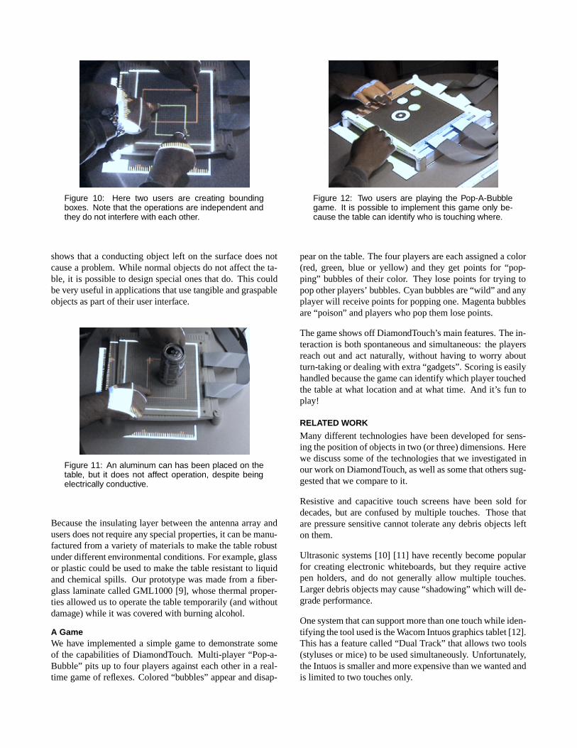
Figure 10: Here two users are creating boundingboxes. Note that the operations are independent andthey do not interfere with each other.
shows that a conducting object left on the surface does notcause a problem. While normal objects do not affect the ta-ble, it is possible to design special ones that do. This couldbe very useful in applications that use tangible and graspableobjects as part of their user interface.
Figure 11: An aluminum can has been placed on thetable, but it does not affect operation, despite beingelectrically conductive.
Because the insulating layer between the antenna array andusers does not require any special properties, it can be manu-factured from a variety of materials to make the table robustunder different environmental conditions. For example, glassor plastic could be used to make the table resistant to liquidand chemical spills. Our prototype was made from a fiber-glass laminate called GML1000 [9], whose thermal proper-ties allowed us to operate the table temporarily (and withoutdamage) while it was covered with burning alcohol.
A GameWe have implemented a simple game to demonstrate someof the capabilities of DiamondTouch. Multi-player “Pop-a-Bubble” pits up to four players against each other in a real-time game of reflexes. Colored “bubbles” appear and disap-
Figure 12: Two users are playing the Pop-A-Bubblegame. It is possible to implement this game only be-cause the table can identify who is touching where.
pear on the table. The four players are each assigned a color(red, green, blue or yellow) and they get points for “pop-ping” bubbles of their color. They lose points for trying topop other players’ bubbles. Cyan bubbles are “wild” and anyplayer will receive points for popping one. Magenta bubblesare “poison” and players who pop them lose points.
The game shows off DiamondTouch’s main features. The in-teraction is both spontaneous and simultaneous: the playersreach out and act naturally, without having to worry aboutturn-taking or dealing with extra “gadgets”. Scoring is easilyhandled because the game can identify which player touchedthe table at what location and at what time. And it’s fun toplay!
RELATED WORK
Many different technologies have been developed for sens-ing the position of objects in two (or three) dimensions. Herewe discuss some of the technologies that we investigated inour work on DiamondTouch, as well as some that others sug-gested that we compare to it.
Resistive and capacitive touch screens have been sold fordecades, but are confused by multiple touches. Those thatare pressure sensitive cannot tolerate any debris objects lefton them.
Ultrasonic systems [10] [11] have recently become popularfor creating electronic whiteboards, but they require activepen holders, and do not generally allow multiple touches.Larger debris objects may cause “shadowing” which will de-grade performance.
One system that can support more than one touch while iden-tifying the tool used is the Wacom Intuos graphics tablet [12].This has a feature called “Dual Track” that allows two tools(styluses or mice) to be used simultaneously. Unfortunately,the Intuos is smaller and more expensive than we wanted andis limited to two touches only.

Other multi-touch systems that cannot identify users includethe FingerWorks FingerBoard [13] and Tactex [14] smartfabric technology. Although the FingerBoard is not ship-ping as of this date, it appears to use a two-dimensional arrayof capacitance sensors to obtain a 2-D “image” of the ob-ject placed on it. The Tactex technology senses pressure bychanges in the optical properties of the material.
Some optical-based input systems have been designed whichtrack hands or other objects around a 2-D area. HoloWall [15]uses a camera and infrared illumination to find objects neara glass wall. Strickon and Paradiso [16] have done some-thing similar in free space using a scanning laser rangefinder.Both system can sense multiple “touches” but cannot easilydistinguish between different users.
Near-field electric field (capacitive) sensing has been used fordecades in applications as simple as touch switches. Moreelaborate forms of capacitive sensing were introduced to theuser interface community in recent years. Zimmerman, etal described this technology in depth in [17] and introducedthe Fish, a device used to measure the position of a hand inthree space using electric fields. Related work can be foundin [18] and [19]. These systems attempt to detect a handor other object that is several centimeters from one of theelectrodes, and use field strength to determine the position.DiamondTouch differs by requiring that the sensed object bevery close (millimeters or less) to an electrode, but uses alarge array of these to sense the position.
CONCLUSIONS AND FUTURE WORKDiamondTouch multi-user touch technology achieves all ofour stated goals. It detects simultaneous, multiple touches,identifying which user is touching each point. It is largelyunaffected by objects left on the surface, and is extremelydurable. There is no stylus to lose, and the entire system canbe manufactured inexpensively.
Larger and Different SystemsWe are interested in building units much larger than ourprototype and see no barriers to doing so. Scaling the elec-tronics should not present a problem. The prototype wassmall because it was made from printed circuit boards, andthese are expensive to make in larger sizes and small quan-tities. Large antenna arrays could be manufactured verycheaply by etching sheets of metalized plastic. We believethat these could be so inexpensive that we can envision a daywhen most white-boards sold will include a DiamondTouchantenna array under the writing surface, ready to plug intoa separately-sold electronics package if the owner wishes tohave touch-input capability.
We have designed and are having manufactured a small runof larger prototype DiamondTouch units. These will be madeby silk-screening conductive ink onto flexible plastic, andwill measure 80 cm by 48 cm with the same0:5 cm row andcolumn pitch as the original prototype. They will connect
to the host computer via a USB interface instead of severalserial ports.
While we have described DiamondTouch’s use in a front-projected format, the technology is certainly not limited tothis. Because the signals are capacitively coupled, very littleelectric current flows through the antennas so these can bemade of a relatively high-resistivity material. This meansthat transparent conductors such as indium tin oxide canbe used, and that the technology will be useful for rear-projection applications as well. Our experiments with suchmaterials are just beginning but show promise.
New ApplicationsThe ability for simultaneous, identifying interaction openssome interesting possibilities. One of the more intriguingideas is the ability to create virtual personal work areas. Weoriginally envisioned DiamondTouch as a method to allowgroup collaboration on a common surface, but in practice,individuals will sometimes want to “break away” to brieflyaddress some subset of the problem, and then wish to inte-grate their result into the whole. When these situations arise,DiamondTouch can create a virtual personal work area infront of the appropriate user that only responds to that user.The user can be manipulating objects in this space, withoutimpacting the larger work effort of other users but for the lossof some table space. Since these virtual personal work areasare software defined, they can be created and destroyed onthe fly, in any shape as desired.
The concept of virtual personal work areas can be extendedto special “privileged objects”. A privileged object is an iconthat allows only certain classes of users to perform certainoperations with that object. For example, a plumber and anelectrician may be viewing the same house plan, but only theplumber can modify the pipes and only the electrician canmodify the wiring.
DiamondTouch’s capability of providing public and privatespaces is the input dual of “Single Display Privacyware” [20],which does the same thing with displayed output. Meshingthese two technologies could provide some interesting userinterface abilities. We are doing research into public/privatedisplay systems here at MERL and plan to experiment witha combination of these and DiamondTouch.
Undoubtedly, more new and interesting applications will ariseas we gain experience with more and larger DiamondTouchdevices.
ACKNOWLEDGMENTSThe authors would like to thank Joe Marks and Kathy Ryallof MERL for both motivating this work, and encouraging usto publish in this forum.
REFERENCES1. Anderson, Anderson, Lesh, Marks, Mirtich, Ratajczak
and Ryall,Human-Guided Simple Searchin Proceed-

ings of AAAI 2000, July 30–August 3, 2000. Austin,TX, USA.
2. Buxton, W., Hill, R. and Rowley, P.,Issues and Tech-niques in Touch-Sensitive Tablet Inputin Proceed-ings of Siggraph ’85 (July 22-26, San Francisco),ACM/Siggraph, 1985, pp. 215–224.
3. Inkpen, K., McGrenere, J., Booth, K. S., and Klawe,M., Turn-Taking Protocols for Mouse-Driven Collabo-rative Environmentsin Proceedings of Graphics Inter-face ’97, Kelowna, BC, May 1997, pp. 138–145.
4. Baxter, L.Capacitive Sensors Design and Applications,IEEE Press, Piscataway, NJ, USA, 1997.
5. Zimmerman, T. G.,Personal Area Networks: Near-field intrabody communicationin IBM Systems Jour-nal, vol. 35, nos. 3&4, 1996, pp. 609–617.
6. Lee, S. K., Buxton, W. and Smith, K. C.,A Multi-TouchThree Dimensional Touch-Sensitive Tabletin Proceed-ings of CHI ’85 (April 1985), ACM/SIGCHI, NY,1985, pp. 21–25.
7. Glisic, S. and Vucetic, B.Spread Spectrum CDMA Sys-tems for Wireless Communications, Artech House, Nor-wood, MA, USA, 1997, pp. 340–341.
8. Dixon, R. Spread Spectrum Systems, 2nd edition,Wiley-Interscience, NY, USA, 1984.
9. GML1000 is a copper clad laminate designed for use inantennas and high frequency circuits requiring low loss.It is available from GIL Technologies of Collierville,TN USA. http://www.gilam.com
10. The Mimio electronic white board.http://www.mimio.com
11. The eBeam Presenter.http://www.e-beam.com
12. The Wacom Intuos graphics tablet.http://www.wacom.com
13. The FingerWorks FingerBoard.http://www.fingerworks.com
14. Tactex Smart Fabric Technology.http://www.tactex.com
15. Matsushita, N. and Rekimoto, J.,HoloWall: Design-ing a Finger, Hand, Body and Object Sensitive WallinProceeding of the ACM UIST ’97 Symposium on UserInterface Software and Technology, 209-210.
16. Strickon, J. and Paradiso, J.,Tracking Hands AboveLarge Interactive Surfaces with a Low-cost ScanningLaser Rangefinderin Proceedings of CHI ’98 ExtendedAbstracts, ACM Press, NY, April 1998, pp. 231–232.
17. Zimmerman, T., Smith, J., Paradiso, J., Allport, D.and Gershenfeld, N.Applying Electric Field Sensingto Human-Computer Interfacesin Proceedings of CHI’95; ACM Conference on Human Factors in ComputingSystems, pp. 280–287.
18. Smith, J. R.Field Mice: Extracting hand Geometryfrom electric field measurementsin IBM Systems Jour-nal, vol. 35, nos. 3&4, 1996, pp. 587–608.
19. Smith, J., White, T., Dodge, C., Paradiso, J., and Ger-shenfeld, N.Electric Field Sensing for Graphical In-terfacesin IEEE Computer Graphics and Applications,vol. 18, no. 3, May-June 1998, pp. 54–60.
20. Shoemaker, G. and Inkpen, K.,Single Display Privacy-ware in Proceedings of CHI 2001, pages 522-529,ACM Press, 2001.