Diagnostic testing of marine propulsion systems with ... · PDF fileDiagnostic testing of...
6
Jacek RUDNICKI PTNSS–2013–SC–026 Zbigniew KORCZEWSKI Diagnostic testing of marine propulsion systems with internal combustion engines by means of vibration measurement and results analysis Abstract: In this paper selected issues concerning vibration diagnosis of the mechanical system within marine propulsion units have been presented, carried out on the basis of experimental examinations of a real object in which an exceedance of the allowable vibration’s level had been observed . Used diagnosing system has been characterised. A procedure of longitudinal and transverse vibrations shaft lines of the mechanical system within marine propusion measurement was presented, with use of portable vibration computerized data logger as well as on the method of vibrations spectral-correlation analysis as a basis of diagnostic process considering dynamic state of analyzed system. Analyzis that has been carried out enabled the selection of the most probable causes for the loss of mechanical system stability. The relevance of the diagnosis was confirmed by the workshop measurements of the torque transmission elements as well as visual inspection of the propellers while the ship was put on a dock. Keywords: technical diagnosis, vibrations measurements, marine propulsion unit, dynamical state Badania diagnostyczne okrętowego zespołu napędowego z tłokowymi silnikami spalinowymi na podstawie pomiarów drgań i analizy ich wyników Streszczenie: W referacie przedstawiono wybrane zagadnienia diagnostyki drganiowej okrętowego zespołu napędowego, na przykładzie eksploatacyjnych badań obiektu rzeczywistego, na którym zaobserwowano zwiększony poziom drgań. Scharakteryzowano zastosowany system diagnozujący. Zaprezentowano procedurę pomiaru drgań wzdłużnych i poprzecznych linii walów okrętowego układu napędowego, z zastosowaniem przenośnego rejestratora drgań oraz metodykę ich analizy widmowo-korelacyjnej, jako podstawę wnioskowania diagnostycznego o stanie dynamicznym rozpatrywanego układu. Przeprowadzona analiza pozwoliła na wskazanie najbardziej prawdopodobnych przyczyn utraty stabilności układu mechanicznego. Trafność postawionej diagnozy potwierdziła weryfikacja warsztatowa elementów transmisji momentu obrotowego oraz oględziny śrub napędowych podczas postoju okrętu w doku. Słowa kluczowe: diagnostyka techniczna, pomiary drgań, okrętowy zespół napędowy, stan dynamiczny 1. Introduction One of the parameters which impacts on dura- bility of the marine propulsion unit’s mechanical system the most is a fatigue strength of material of which its structure is built. During an engine’s operation on a sailing ship because of multifold changes of mechanical loads (caused by periodical- ly changeable reactions of forces and torques gen- erated by propulsion engines, propellers and a ship hull operating on waves) cyclic elastic and plastic shaftings deformations take place. They give rise to transverse, axial and torsional vibrations – Fig. 1. That means a loss of the mechanical system’s sta- bility as well as a resonance phenomenon to appear in a global and local sense. The increasing ampli- tudes of changeable internal stresses stand for the cause of a considerable limitation of the cycle num- ber of load alterations, at which elements transmit- ting torque from the engine to the propeller are subject to the accelerated wear and tear process until the irreversible failures occur (cracks, deterio- ration of constructional material’s strength charac- teristics) because of material fatigue. The loss of stability of the mechanical system within marine propulsion unit under operation results from an occurrence and development of the following det- rimental phenomena: a slowly worsening unbalance state of shaftings and propeller resulting from sed- iments, erosion, corrosion and bent shafts or a loss of their alignment, a sudden increase of shafting unbalance state resulting from deformations or broken-off fragments of propeller blades, excess of allowable load of bearings, shafts seizing in slide bearings, failures within rolling bearings etc. All the above specified factors worsen a dynam- ic state of the propulsion unit, enlarging a quantity of dissipated kinetic energy that has to be devoted to extort a vibration. However, the results of relia- bility investigations carried out on marine propul- sion systems univocally show that the excessive load among the main engine cylinders represents the most frequent cause of the enlarged level of the shafting torsional and axial vibration. As far as the transverse and axial vibration is concerned - the Article citation info: RUDNICKI, J., KORCZEWSKI, Z. Diagnostic testing of marine propulsion systems with internal combustion engines by means of vibration measurement and results analysis. Combustion Engines. 2013, 154(3), 308-313. ISSN 0138-0346. 308
Transcript of Diagnostic testing of marine propulsion systems with ... · PDF fileDiagnostic testing of...
Jacek RUDNICKI PTNSS–2013–SC–026 Zbigniew KORCZEWSKI
Diagnostic testing of marine propulsion systems with internal
combustion engines by means of vibration measurement
and results analysis
Abstract: In this paper selected issues concerning vibration diagnosis of the mechanical system within
marine propulsion units have been presented, carried out on the basis of experimental examinations of a real
object in which an exceedance of the allowable vibration’s level had been observed. Used diagnosing system has
been characterised. A procedure of longitudinal and transverse vibrations shaft lines of the mechanical system
within marine propusion measurement was presented, with use of portable vibration computerized data logger
as well as on the method of vibrations spectral-correlation analysis as a basis of diagnostic process considering
dynamic state of analyzed system. Analyzis that has been carried out enabled the selection of the most probable
causes for the loss of mechanical system stability. The relevance of the diagnosis was confirmed by the workshop
measurements of the torque transmission elements as well as visual inspection of the propellers while the ship
was put on a dock.
Keywords: technical diagnosis, vibrations measurements, marine propulsion unit, dynamical state
Badania diagnostyczne okrętowego zespołu napędowego z tłokowymi silnikami
spalinowymi na podstawie pomiarów drgań i analizy ich wyników
Streszczenie: W referacie przedstawiono wybrane zagadnienia diagnostyki drganiowej okrętowego zespołu
napędowego, na przykładzie eksploatacyjnych badań obiektu rzeczywistego, na którym zaobserwowano
zwiększony poziom drgań. Scharakteryzowano zastosowany system diagnozujący. Zaprezentowano procedurę
pomiaru drgań wzdłużnych i poprzecznych linii walów okrętowego układu napędowego, z zastosowaniem
przenośnego rejestratora drgań oraz metodykę ich analizy widmowo-korelacyjnej, jako podstawę wnioskowania
diagnostycznego o stanie dynamicznym rozpatrywanego układu. Przeprowadzona analiza pozwoliła na
wskazanie najbardziej prawdopodobnych przyczyn utraty stabilności układu mechanicznego. Trafność
postawionej diagnozy potwierdziła weryfikacja warsztatowa elementów transmisji momentu obrotowego oraz
oględziny śrub napędowych podczas postoju okrętu w doku.
Słowa kluczowe: diagnostyka techniczna, pomiary drgań, okrętowy zespół napędowy, stan dynamiczny
1. Introduction
One of the parameters which impacts on dura-
bility of the marine propulsion unit’s mechanical
system the most is a fatigue strength of material of
which its structure is built. During an engine’s
operation on a sailing ship because of multifold
changes of mechanical loads (caused by periodical-
ly changeable reactions of forces and torques gen-
erated by propulsion engines, propellers and a ship
hull operating on waves) cyclic elastic and plastic
shaftings deformations take place. They give rise to
transverse, axial and torsional vibrations – Fig. 1.
That means a loss of the mechanical system’s sta-
bility as well as a resonance phenomenon to appear
in a global and local sense. The increasing ampli-
tudes of changeable internal stresses stand for the
cause of a considerable limitation of the cycle num-
ber of load alterations, at which elements transmit-
ting torque from the engine to the propeller are
subject to the accelerated wear and tear process
until the irreversible failures occur (cracks, deterio-
ration of constructional material’s strength charac-
teristics) because of material fatigue. The loss of
stability of the mechanical system within marine
propulsion unit under operation results from an
occurrence and development of the following det-
rimental phenomena: a slowly worsening unbalance
state of shaftings and propeller resulting from sed-
iments, erosion, corrosion and bent shafts or a loss
of their alignment, a sudden increase of shafting
unbalance state resulting from deformations or
broken-off fragments of propeller blades, excess of
allowable load of bearings, shafts seizing in slide
bearings, failures within rolling bearings etc.
All the above specified factors worsen a dynam-
ic state of the propulsion unit, enlarging a quantity
of dissipated kinetic energy that has to be devoted
to extort a vibration. However, the results of relia-
bility investigations carried out on marine propul-
sion systems univocally show that the excessive
load among the main engine cylinders represents
the most frequent cause of the enlarged level of the
shafting torsional and axial vibration. As far as the
transverse and axial vibration is concerned - the
Article citation info:
RUDNICKI, J., KORCZEWSKI, Z. Diagnostic testing of marine propulsion systems with internal combustion engines by means of vibration
measurement and results analysis. Combustion Engines. 2013, 154(3), 308-313. ISSN 0138-0346.
308

loss of shaftings alignment as well as propellers'
damages [4, 6].
In the operation practice the measurements of
torsional vibration are performed only on the pro-
pulsion units which are especially prepared for this
aim. The low supervisory susceptibility in this
range of serial propulsion units considerably limits
a credibility of the gathered measuring results [1,
2]. Hence, in case of affirming the raised vibration
of the ship hull, first of all, the main engine cylin-
ders indication should be done. Then, when the
cylinders are eliminated as the potential source of
the generated vibration, measurements and the
analysis of transverse and axial vibration in the
selected constructional points of the propulsion
units are carried out. The main purpose of the con-
ducted investigations is to claim whether the
changeable transverse or axial stresses, caused by
the vibration, exceed admissible values or not. The
stresses, after achieving definite (for the given con-
structional material) cycles number lead to the
fatigue damages.
Fig. 1. Force and torque system that impels a marine
shafting vibration [3]
The affected transverse and axial vibration oc-
cur within propulsion shafts practically in the whole
range of rotational speed alterations. Nevertheless,
the largest amplitudes appear at the resonance rota-
tional speeds. In order to identify the resonance's
sources vibration a spectral analysis of the regis-
tered vibration signal should be conducted. It con-
sists in the signal decomposition into harmonic
components of the determined resonance frequen-
cies. The condensation of amplitude spectrum as
well as the growth of amplitudes of the characteris-
tic harmonic components testifies about the exist-
ence of local resonances and the deterioration of the
propulsion unit's dynamic state threatening with the
damages of elements which transmit a torque to the
propeller.
The transverse and axial vibration issue in terms
of their measurements and spectral-correlation
analysis has been introduced in numerous publica-
tions in detail. However, there is still perceptible
lack of bibliographic positions presenting this ques-
tion in the aspect of the widely understood opera-
tion diagnostics. Just the Authors were guided by
such a purpose during editing the present article.
2. Research object characterization
An experimental testing, carried out on the three
shaft homogeneous drivetrain (Fig. 3) while the
ship was operating, was designed to check a stabil-
ity of the propulsion’s mechanical system. To carry
out the programme of testing it was necessary to
put the ship to sea and several cycles of vibration
measurements were made.
The diagnostic investigations were conducted
on the Baltic Sea, at the sea state about 2÷3.
During the measurements, all the main engines
were running simultaneously (a common work),
and besides the vibration signals the additional
control parameters were observed, as follows:
rotational speed of the propeller shafts - 282
rev/min,
steady load: the engines' rotational speeds n =
800 rev/min, the engines' load indexes: PS en-
gine Wo=6.5, SB engine Wo=6.8 and Central
engine Wo=7.0,
floating speed: 14 knots,
temperatures: tube stuffings 18 - 200C, radial
bearings of the tunnel shafts 35 - 370C, gear-
boxes 47 - 500C.
Operation diagnostic measurements were
worked out by means of SVAN 956 digital vibra-
tion measuring instrument of SVANTEK Ltd. pro-
duction [http://svantek.com]. It gives a possibility
of the following trends of values' alterations of the
spectrum parameters in different characteristic
frequency bands, for the well-known and recog-
nizable states of operation unfitness.
SVAN956 is equipped with DYTRAN piezoe-
lectric acceleration sensor 3185D type. A magnetic
connection of the sensor makes a quick exchange of
the measurement place possible, which has got the
very essential meaning in case of variable and lim-
ited conditions of the measurement's realization.
Three independent measuring profiles applied in the
analyzer permit selecting three filter sets and time-
constants for the simultaneous measurement of
vibration's acceleration, velocity and displacement
within the frequency range from 0.5 kHz to 20 kHz
(limited with a transfer band of the applied trans-
ducer). Thanks to the large power of a signal pro-
cessor the simultaneous narrow-band analysis FFT,
the simultaneous frequency analyses within the
octave- and tercial-bands as well as the simultane-
ous analysis of vibration envelope are possible
during the measurements. There is also accessible
the register's function of a whirling machine balanc-
ing, which requires a simultaneous rotational speed
and vibration measurement.
309
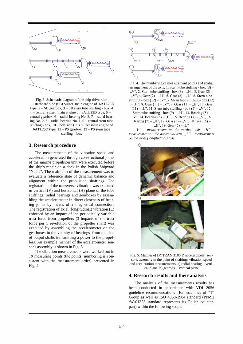
Fig. 3. Schematic diagram of the ship drivetrain:
1 – starboard side (SB) Sulzer main engine of 6ATL25D
type, 2 – SB gearbox, 3 – SB stern tube stuffing - box, 4
– central Sulzer main engine of 6ATL25D type, 5 –
central gearbox, 6 – radial bearing No. 3, 7 – radial bear-
ing No. 2, 8 – radial bearing No. 1, 9 – central stern tube
stuffing - box, 10 – port side (PS) Sulzer main engine of
6ATL25D type, 11 – PS gearbox, 12 – PS stern tube
stuffing – box
3. Research procedure
The measurements of the vibration speed and
acceleration generated through constructional joints
of the marine propulsion unit were executed before
the ship's repair on a dock in the Polish Shipyard
"Nauta". The main aim of the measurement was to
evaluate a reference state of dynamic balance and
alignment within the propulsion shaftings. The
registration of the transverse vibration was executed
in vertical (V) and horizontal (H) plane of the tube
stuffings, radial bearings and gearboxes by assem-
bling the accelerometer in direct closeness of bear-
ing joints by means of a magnetical connection.
The registration of axial (longitudinal) vibration (L)
enforced by an impact of the periodically variable
trust force from propellers (3 impacts of the trust
force per 1 revolution of the propeller shaft) was
executed by assembling the accelerometer on the
gearboxes in the vicinity of bearings, from the side
of output shafts transmitting a power to the propel-
lers. An example manner of the accelerometer sen-
sor's assembly is shown in Fig. 5.
The vibration measurements were worked out in
19 measuring points (the points’ numbering is con-
sistent with the measurement order) presented in
Fig. 4
Fig. 4. The numbering of measurement points and spatial
arrangement of the axis: 1. Stern tube stuffing - box (3) –
„V”, 2. Stern tube stuffing - box (3) – „H”, 3. Gear (2) –
„V”, 4. Gear (2) – „H”, 5. Gear (2) – „L”, 6. Stern tube
stuffing - box (12) – „V”, 7. Stern tube stuffing - box (12)
– „H”, 8. Gear (11) – „V”, 9. Gear (11) – „H”, 10. Gear
(11) – „L”, 11. Stern tube stuffing - box (9) – „V”, 12.
Stern tube stuffing - box (9) – „H”, 13. Bearing (8) –
„V”, 14. Bearing (8) – „H”, 15. Bearing (7) – „V”, 16.
Bearing (7) – „H”, 17. Gear (5) – „V”, 18. Gear (5) –
„H”, 19. Gear (5) – „L”
„V” – measurement on the vertical axis, „H” –
measurement on the horizontal axis, „L” – measurement
on the axial (longitudinal) axis
Fig. 5. Manner of DYTRAN 3185 D accelerometer sen-
sor's assembly in the point of shaftings vibration speed
and acceleration measurements: a) radial bearing – verti-
cal plane, b) gearbox – vertical plane
4. Research results and their analysis
The analysis of the measurements results has
been conducted in accordance with VDI 2056
guideline recommendations for machines of "T"
Group as well as ISO 4868-1984 standard (PN-92
/W-01353 standard represents its Polish counter-
part) within the following scope:
310

root mean square (RMS) value of the vibration
velocity - measured in the frequency range of
10Hz to 1kHz,
amplitude spectrum of the vibration velocity
and acceleration in relation to basic frequen-
cies harmonics of the propeller shafts rotation-
al speed as well as characteristic frequencies
associated with the main engines work (3
gasdynamical cycles (extortions) per 1 crank-
shaft revolution), the shafting carrying bear-
ings as well as the propellers (3 trust force ex-
tortions per 1 revolution of the propeller
shaft), for every propulsion unit.
The gathered RMS vibration date is presented in
Tab. 1. The results of FFT (Fast Fourier Transform)
in the plot form of vibration amplitude vs. frequen-
cy are demonstrated in Fig. 7 9. This is a basic
analytical method most often used in diagnosing
faults associated with unbalance, misalignment,
eccentric components and damaged bearings, shafts
or gears [1, 2].
The measurement results showed in Tab.1 con-
firm that the vibration parameters characterizing the
stability of the mechanical system within the central
and starboard propulsion units exceeded operational
tolerance's borders, in accordance with VDI guide-
line 2056 (ISO-10816), which serve as the basic
standards regarding execution of the measurements,
selection of the measuring points and limits of ma-
chine dynamic state evaluation [www.iso.org/].
The highest RMS amplitude values of the vibra-
tion velocity were registered in the constructional
joints as follows:
on the casing of central shaftline’s bearing No.
1 (the first one from the tube stuffing), in the
horizontal axis - the amplitude YRMS = 12,4
mm/s;
on the casing of central shaftline’s bearing No.
2, in the vertical axis - the amplitude YRMS =
29,6 mm/s;
on the casing of the starboard reductive gear-
box, in the axial (longitudinal) axis - the am-
plitude YRMS = 25,1 mm/s.
Tab. 1. Vibration data spreadsheet
RMS amplitude represents an indication of the
amount of vibration energy in the ship propulsion
unit’s mechanical system (the amount of dissipated
kinetic energy within this system). One should be
aware that the higher the vibration energy, the
higher RMS velocity amplitude.
On the basis of vibration measurements and
their analysis two possible causes of inadmissible
dynamic state of the central and starboard shaftlines
were pointed out: the shaftline misalignment or the
worsened balance state caused probably by the
shaft bending or propellers' damages. Such a formu-
lated diagnosis confirmed results of technical state
workshop verification carried out after the ship was
undocked in the shipyard, when widespread dam-
ages of the ship propellers were detected - Fig. 6.
a)
b)
Fig. 6. Results of visual inspection of the propellers while
the ship was put on the shipyard dock: a) damages of the
port side propeller, b) damages of the starboard propeller
The port side propulsion unit does not reveal
any symptoms of the worsened dynamic state.
The conducted frequency analysis of the regis-
tered vibration velocity spectrum in the vulnerable,
neuralgic joints of the central and starboard propul-
sion units (Fig. 7) showed an undesirable condensa-
tion of the amplitude spectra in the vicinity of rang-
es of the propeller and propeller shaft proper vibra-
tion.
311

Fig. 8. Velocity spectrum of vibrat-
ing bearing casing No.1, registered
in horizontal plane – H axis, measur-
ing point number 14
Fig. 7. Velocity spectrum of vibrat-
ing SB gearbox, registered in verti-
cal plane – V axis, measuring point
number 3
Fig. 9. Velocity spectrum of vibrat-
ing bearing casing No.2, registered
in vertical plane – V axis, measuring
point number 15
312

There was additionally observed was, that the am-
plitude of characteristic subharmonic frequency 1/3
f0 equalled 1,56 Hz (94 rpm) predominated within
the spectra. It usually represents the main source of
vibration extortion in radial direction derived from
the enlarged clearance of a slide bearing in the
casing (Fig. 8 and 9)
5. Conclusions
Vibration measurements and analysis represent an
important indicator of the current stability state of a
marine propulsion unit’s mechanical system. The
authors aimed to prove that the operational vibra-
tion investigations can be conducted easily, effec-
tively and successfully even by means of a very
simple measurement apparatus.
The presented results of the diagnostic examination
of three-shaft marine drivetrain confirm the im-
portance of three distinct components of the com-
plete vibration analysis: absolute vibration meas-
urements, bearing condition measurements and FFT
frequency analysis enabling diagnosing faults asso-
ciated with the propulsion mechanical system, in
this case – the propellers.
Bibliography/Literatura
[1] ADAMS, M.L.: Rotating Machinery Vibra-
tion: From Analysis to Troubleshooting. New
York: Marcel Dekker, 2001.
[2] BENTLY, D.E. and HATCH, C.T.: Funda-
mentals of Rotating Machinery Diagnostics.
Minden: Bently Pressurized Bearing Press,
2002.
[3] CUDNY, K.: Linie wałów okrętowych.
Gdańsk: Wydawnictwo Morskie, 1976.
[4] DRAGANTCHEV, H.: Control and Diagnos-
tics of Ship Shafting. Proceedings of the
IMAM 2000, Ischia, April 2-6, Session L,
115-122.
[5] KORCZEWSKI, Z.: Endoskopia silników
okrętowych. Gdynia: AMW Gdynia, 2008.
[6] Gdansk University of Technology, Poland:
Reports of diagnostic investigations of the
marine propulsion systems – Research Re-
ports, Gdańsk 2009 – 2011.
Prof. Zbigniew Korczewski, DSc, PhD –
Head of the Department of Marine and
Land Power Plants in the Faculty of Ocean Engineering & Ship Technology
at the Gdansk University of Technology.
Prof. dr hab. inż. Zbigniew Korczewski - Kierownik Katedry Siłowni Morskich i
Lądowych na Wydziale Oceanotechniki i
Okrętownictwa Politechniki Gdańskiej.
e-mail: [email protected]
Mr Jacek Rudnicki, PhD, MEng. –
Doctor in the Faculty of Ocean
Engineering and Ship Technology at Gdańsk University of Technology.
Dr inż. Jacek Rudnicki – adiunkt
na Wydziale Oceanotechniki i
Okrętownictwa Politechniki Gdań-skiej.
313