DH485/RS-232C Interface Module · DH485/RS-232C Interface Module (Catalog Number 1747-KE) ......
24
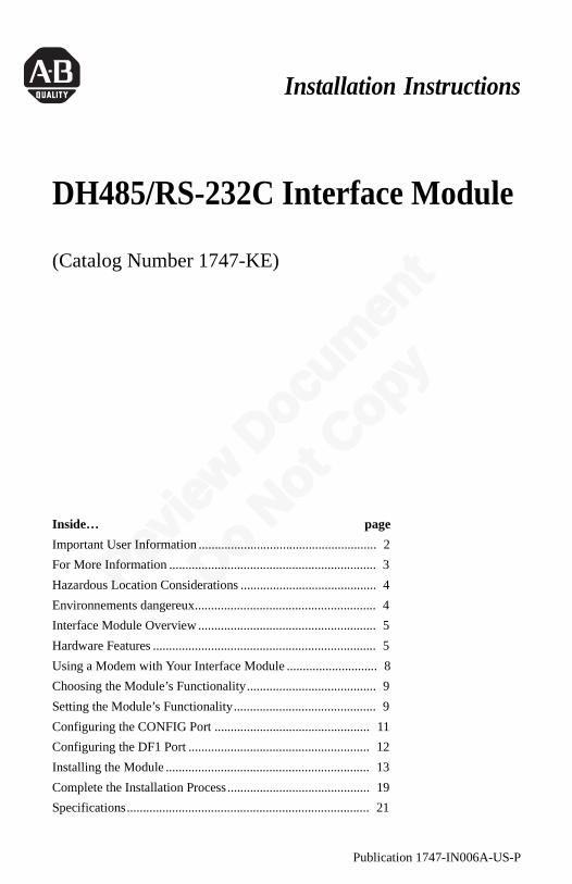
Review Document Do Not Copy Publication 1747-IN006A-US-P Installation Instructions DH485/RS-232C Interface Module (Catalog Number 1747-KE) Inside… page Important User Information ....................................................... 2 For More Information ................................................................ 3 Hazardous Location Considerations .......................................... 4 Environnements dangereux........................................................ 4 Interface Module Overview ....................................................... 5 Hardware Features ..................................................................... 5 Using a Modem with Your Interface Module ............................ 8 Choosing the Module’s Functionality ........................................ 9 Setting the Module’s Functionality ............................................ 9 Configuring the CONFIG Port ................................................ 11 Configuring the DF1 Port ........................................................ 12 Installing the Module ............................................................... 13 Complete the Installation Process ............................................ 19 Specifications ........................................................................... 21
Transcript of DH485/RS-232C Interface Module · DH485/RS-232C Interface Module (Catalog Number 1747-KE) ......
Revie
w Doc
umen
t
Do Not
Copy
Publication 1747-IN006A-US-P
Installation Instructions
DH485/RS-232C Interface Module
(Catalog Number 1747-KE)
Inside… page
Important User Information ....................................................... 2
For More Information ................................................................ 3
Hazardous Location Considerations .......................................... 4
Environnements dangereux........................................................ 4
Interface Module Overview ....................................................... 5
Hardware Features ..................................................................... 5
Using a Modem with Your Interface Module ............................ 8
Choosing the Module’s Functionality........................................ 9
Setting the Module’s Functionality............................................ 9
Configuring the CONFIG Port ................................................ 11
Configuring the DF1 Port ........................................................ 12
Installing the Module ............................................................... 13
Complete the Installation Process............................................ 19
Specifications........................................................................... 21

Revie
w Doc
umen
t
Do Not
Copy
2 DH485/RS-232C Interface Module
Publication 1747-IN006A-US-P
Important User InformationBecause of the variety of uses for the products described in this publication, those responsible for the application and use of this control equipment must satisfy themselves that all necessary steps have been taken to assure that each application and use meets all performance and safety requirements, including any applicable laws, regulations, codes and standards.
The illustrations, charts, sample programs and layout examples shown in this guide are intended solely for purposes of example. Since there are many variables and requirements associated with any particular installation, Allen-Bradley does not assume responsibility or liability (to include intellectual property liability) for actual use based upon the examples shown in this publication.
Allen-Bradley publication SGI-1.1, Safety Guidelines for the Application, Installation, and Maintenance of Solid-State Control (available from your local Allen-Bradley office), describes some important differences between solid-state equipment and electromechanical devices that should be taken into consideration when applying products such as those described in this publication.
Reproduction of the contents of this copyrighted publication, in whole or in part, without written permission of Allen-Bradley Company, Inc., is prohibited.
Throughout these installation instructions we use notes to make you aware of safety considerations:
Attention statements help you to:
• identify a hazard
• avoid the hazard
• recognize the consequences
!
ATTENTIONIdentifies information about practices or circumstances that can lead to personal injury or death, property damage or economic loss.
IMPORTANT Identifies information that is critical for successful application and understanding of the product.

Revie
w Doc
umen
t
Do Not
Copy
3 DH485/RS-232C Interface Module
Publication 1747-IN006A-US-P
For More Information
Related Publications
How to Get More Information
If you would like a manual, you can:
• download a free electronic version from the internet at www.theautomationbookstore.com
• purchase a printed manual by:
– contacting your local distributor or Rockwell Automation representative
– visiting www.theautomationbookstore.com and placing your order
– calling 1.800.963.9548 (USA/Canada) or 001.330.725.1547 (Outside USA/Canada)
For Refer to this Document Pub. No.
A more detailed description on how to install and use your RTD/Resistance Input Module.
DH485/RS-232C Interface Module User Manual
1747-6.12
A more detailed description on how to install and use your modular SLC 500 system.
SLC 500™ Modular Hardware Style Installation and Operation Manual
1747-6.2
A more detailed description on how to install and use your fixed SLC 500 system.
SLC 500™ Fixed Hardware Style Installation and Operation Manual
1747-6.21
A reference manual that contains status file data, instruction set, and troubleshooting information.
SLC 500™ and MicroLogix™ 1000 Instruction Set Reference Manual
1747-6.15

Revie
w Doc
umen
t
Do Not
Copy
4 DH485/RS-232C Interface Module
Publication 1747-IN006A-US-P
Hazardous Location ConsiderationsThis equipment is suitable for use in Class I, Division 2, Groups A, B, C, D or non-hazardous locations only. The following WARNING statement applies to use in hazardous locations.
Environnements dangereuxCet équipement est conçu pour être utilisé dans des environnements de Classe 1, Division 2, Groupes A, B, C, D ou non dangereux. La mise en garde suivante s’applique à une utilisation dans des environnements dangereux.
!
WARNING EXPLOSION HAZARD
• Substitution of components may impair suitability for Class I, Division 2.
• Do not replace components or disconnect equipment unless power has been switched off.
• Do not connect or disconnect components unless power has been switched off.
• All wiring must comply with N.E.C. article 501-4(b).
MISE EN
!
DANGER D’EXPLOSION
• La substitution de composants peut rendre cet équipement impropre à une utilisation en environnement de Classe 1, Division 2.
• Ne pas remplacer de composants ou déconnecter l'équipement sans s'être assuré que l'alimentation est coupée.
• Ne pas connecter ou déconnecter des composants sans s'être assuré que l'alimentation est coupée.
Revie
w Doc
umen
t
Do Not
Copy
5 DH485/RS-232C Interface Module
Publication 1747-IN006A-US-P
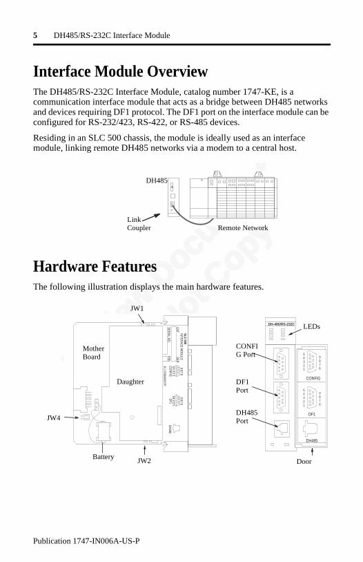
Interface Module OverviewThe DH485/RS-232C Interface Module, catalog number 1747-KE, is a communication interface module that acts as a bridge between DH485 networks and devices requiring DF1 protocol. The DF1 port on the interface module can be configured for RS-232/423, RS-422, or RS-485 devices.
Residing in an SLC 500 chassis, the module is ideally used as an interface module, linking remote DH485 networks via a modem to a central host.
Hardware FeaturesThe following illustration displays the main hardware features.
Link Coupler Remote Network
DH485
DH-485/RS-232C
SLC 500IN
TERAC
E MO
DU
LEC
ATSER
SERIAL N
O.
FRN
12
345
678
9CO
NFIG
12
345
678
9DF1
DH
485
CONFIG
54321
9876
DF1
54321
9876
DH485
LEDs
Door
JW1
JW2
JW4
Mother Board
Daughter
CONFIG Port
DF1 Port
DH485 Port
Battery
Revie
w Doc
umen
t
Do Not
Copy
6 DH485/RS-232C Interface Module
Publication 1747-IN006A-US-P
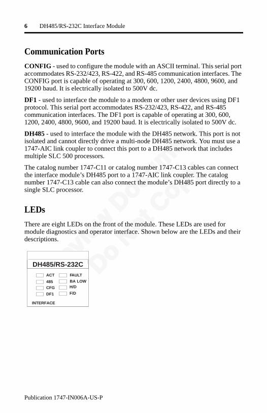
Communication Ports
CONFIG - used to configure the module with an ASCII terminal. This serial port accommodates RS-232/423, RS-422, and RS-485 communication interfaces. The CONFIG port is capable of operating at 300, 600, 1200, 2400, 4800, 9600, and 19200 baud. It is electrically isolated to 500V dc.
DF1 - used to interface the module to a modem or other user devices using DF1 protocol. This serial port accommodates RS-232/423, RS-422, and RS-485 communication interfaces. The DF1 port is capable of operating at 300, 600, 1200, 2400, 4800, 9600, and 19200 baud. It is electrically isolated to 500V dc.
DH485 - used to interface the module with the DH485 network. This port is not isolated and cannot directly drive a multi-node DH485 network. You must use a 1747-AIC link coupler to connect this port to a DH485 network that includes multiple SLC 500 processors.
The catalog number 1747-C11 or catalog number 1747-C13 cables can connect the interface module’s DH485 port to a 1747-AIC link coupler. The catalog number 1747-C13 cable can also connect the module’s DH485 port directly to a single SLC processor.
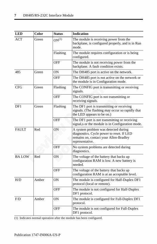
LEDs
There are eight LEDs on the front of the module. These LEDs are used for module diagnostics and operator interface. Shown below are the LEDs and their descriptions.
DH485/RS-232CACT
485CFG
DF1
FAULT
BA LOWH/D
F/D
INTERFACE
Revie
w Doc
umen
t
Do Not
Copy
7 DH485/RS-232C Interface Module
Publication 1747-IN006A-US-P
LED Color Status Indication
ACT Green ON(1)
(1) Indicates normal operation after the module has been configured.
The module is receiving power from the backplane, is configured properly, and is in Run mode.
Flashing The module requires configuration or is being configured.
OFF The module is not receiving power from the backplane. A fault condition exists.
485 Green ON The DH485 port is active on the network.
OFF The DH485 port is not active on the network or the module is in Configuration mode.
CFG Green Flashing The CONFIG port is transmitting or receiving signals.
OFF The CONFIG port is not transmitting or receiving signals.
DF1 Green Flashing The DF1 port is transmitting or receiving signals. (The flashing may occur so rapidly that the LED appears to be on.)
OFF The DF1 port is not transmitting or receiving signal,s or the module is in Configuration mode.
FAULT Red ON A system problem was detected during diagnostics. Cycle power to reset. If LED remains on, contact your Allen-Bradley representative.
OFF No system problems are detected during diagnostics.
BA LOW Red ON The voltage of the battery that backs up configuration RAM is low. A new battery is needed.
OFF The voltage of the battery that backs up configuration RAM is at an acceptable level.
H/D Amber ON The module is configured for Half-Duplex DF1 protocol (local or remote).
OFF The module is not configured for Half-Duplex DF1 protocol.
F/D Amber ON The module is configured for Full-Duplex DF1 protocol.
OFF The module is not configured for Full-Duplex DF1 protocol.
Revie
w Doc
umen
t
Do Not
Copy
8 DH485/RS-232C Interface Module
Publication 1747-IN006A-US-P
Jumpers
JW1 allows you to select the communication interface for the CONFIG port. See page 11.
JW2 allows you to select the communication interface for the DF1 port. See page 12.
JW4 allows you to select the functionality and mode of the interface module. The horizontal or vertical orientation of the jumper determines the module’s functionality.
The position of the jumper determines the module’s mode (Configuration or Run), and thus, which method is used to configure the module (ASCII terminal or backplane communications). See page 10.
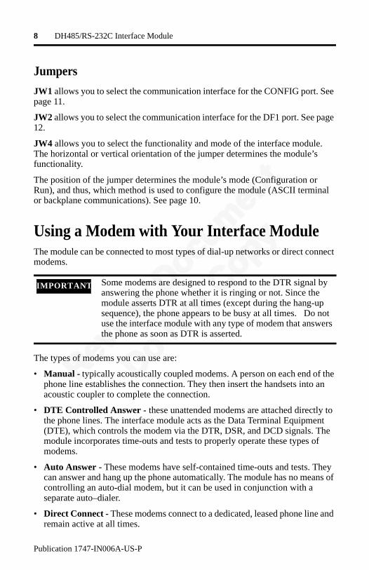
Using a Modem with Your Interface ModuleThe module can be connected to most types of dial-up networks or direct connect modems.
The types of modems you can use are:
• Manual - typically acoustically coupled modems. A person on each end of the phone line establishes the connection. They then insert the handsets into an acoustic coupler to complete the connection.
• DTE Controlled Answer - these unattended modems are attached directly to the phone lines. The interface module acts as the Data Terminal Equipment (DTE), which controls the modem via the DTR, DSR, and DCD signals. The module incorporates time-outs and tests to properly operate these types of modems.
• Auto Answer - These modems have self-contained time-outs and tests. They can answer and hang up the phone automatically. The module has no means of controlling an auto-dial modem, but it can be used in conjunction with a separate auto–dialer.
• Direct Connect - These modems connect to a dedicated, leased phone line and remain active at all times.
IMPORTANT Some modems are designed to respond to the DTR signal by answering the phone whether it is ringing or not. Since the module asserts DTR at all times (except during the hang-up sequence), the phone appears to be busy at all times. Do not use the interface module with any type of modem that answers the phone as soon as DTR is asserted.
Revie
w Doc
umen
t
Do Not
Copy
9 DH485/RS-232C Interface Module
Publication 1747-IN006A-US-P
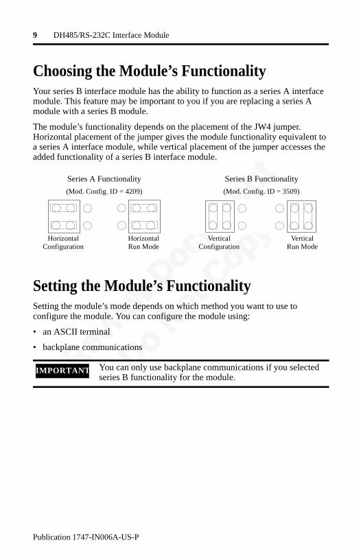
Choosing the Module’s FunctionalityYour series B interface module has the ability to function as a series A interface module. This feature may be important to you if you are replacing a series A module with a series B module.
The module’s functionality depends on the placement of the JW4 jumper. Horizontal placement of the jumper gives the module functionality equivalent to a series A interface module, while vertical placement of the jumper accesses the added functionality of a series B interface module.
Setting the Module’s FunctionalitySetting the module’s mode depends on which method you want to use to configure the module. You can configure the module using:
• an ASCII terminal
• backplane communications
IMPORTANT You can only use backplane communications if you selected series B functionality for the module.
Series A Functionality
(Mod. Config. ID = 4209)
Series B Functionality
(Mod. Config. ID = 3509)
HorizontalConfiguration
HorizontalRun Mode
VerticalConfiguration
VerticalRun Mode

Revie
w Doc
umen
t
Do Not
Copy
10 DH485/RS-232C Interface Module
Publication 1747-IN006A-US-P
If Configuring with an ASCII Terminal
Configuration of the interface module with an ASCII terminal is allowed only when the JW4 jumper is in Configuration mode. Place the module in the Configuration mode that corresponds to the functionality you chose for the interface module, as shown below.
If Configuring Through the Backplane
Reading and writing configuration data through the backplane is allowed only for series B interface modules, and then only when the JW4 jumper is in the vertical Run mode position. Place the module in vertical Run mode as shown below.
For Series A FunctionalityFor Series B Functionality
Horizontal Configuration Vertical Configuration
JW4 JW4
JW4
Vertical Run
Revie
w Doc
umen
t
Do Not
Copy
11 DH485/RS-232C Interface Module
Publication 1747-IN006A-US-P
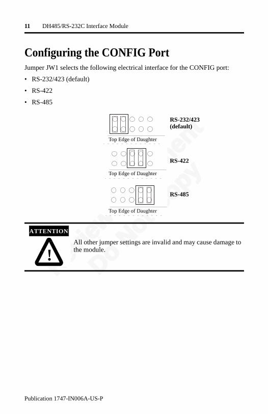
Configuring the CONFIG PortJumper JW1 selects the following electrical interface for the CONFIG port:
• RS-232/423 (default)
• RS-422
• RS-485
!
ATTENTION
All other jumper settings are invalid and may cause damage to the module.
RS-232/423(default)
RS-422
RS-485
Top Edge of Daughter
Top Edge of Daughter
Top Edge of Daughter
Revie
w Doc
umen
t
Do Not
Copy
12 DH485/RS-232C Interface Module
Publication 1747-IN006A-US-P
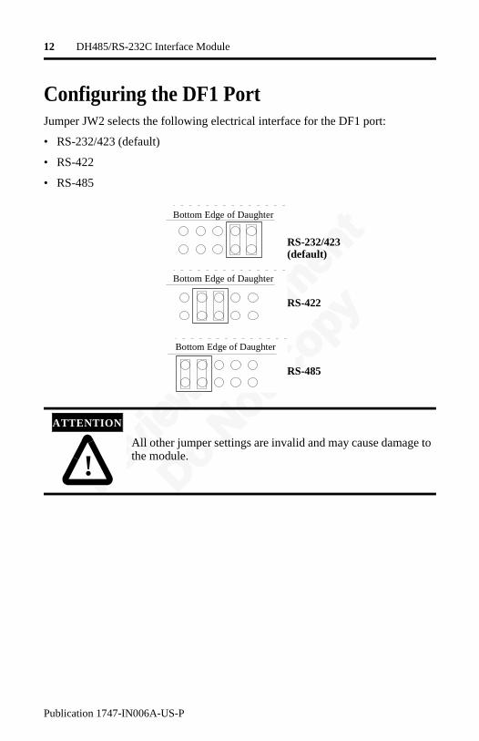
Configuring the DF1 PortJumper JW2 selects the following electrical interface for the DF1 port:
• RS-232/423 (default)
• RS-422
• RS-485
!
ATTENTION
All other jumper settings are invalid and may cause damage to the module.
RS-232/423(default)
RS-422
RS-485
Bottom Edge of Daughter
Bottom Edge of Daughter
Bottom Edge of Daughter
Revie
w Doc
umen
t
Do Not
Copy
13 DH485/RS-232C Interface Module
Publication 1747-IN006A-US-P
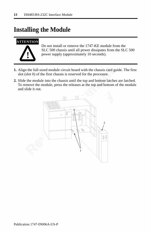
Installing the Module
1. Align the full-sized module circuit board with the chassis card guide. The first slot (slot 0) of the first chassis is reserved for the processor.
2. Slide the module into the chassis until the top and bottom latches are latched. To remove the module, press the releases at the top and bottom of the module and slide it out.
!
ATTENTIONDo not install or remove the 1747-KE module from the SLC 500 chassis until all power dissipates from the SLC 500 power supply (approximately 10 seconds).
2
1
Revie
w Doc
umen
t
Do Not
Copy
14 DH485/RS-232C Interface Module
Publication 1747-IN006A-US-P
Connect Cable to CONFIG or DF1 Ports
The CONFIG and DF1 ports communicate to user devices through RS-232/423, RS-422, and RS-485 communication modes. The communication mode is selected by setting jumpers JW1 and JW2 as described on pages 11 and 12.
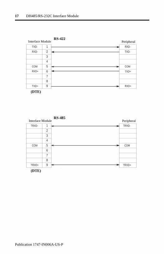
Use these pin assignments to construct communication cables for the CONFIG and DF1 ports. These connectors must be wired to correspond to the selected communication mode.
IMPORTANT The following table and cable drawings assume the peripheral devices have conventional pin assignments. Check the documentation for your device to verify that the signals conform to those shown.
Pin for Interface Module
RS-232/423Signal
RS-422Signal
RS-485Signal
IBM AT Standard RS-232/423
Signal 25-pin Pin
9-pin Pin
1 (1)
(1) In RS-423 mode, these pins are still connected to their RS-422 loads. Do not use these pins in RS-423 mode.
TXD- TRXD- DCD or CD
8 1
2 RXD RXD- (3)
(3) In RS-485 mode, these pins are still connected to their RS-422 receivers. Do not use these pins in RS-485 mode.
RXD 3 2
3 TXD (2)
(2) In RS-422 and RS-485 modes these pins are connected to their RS-423 drivers and receivers. Do not use these pins in either RS-422 or RS-485 modes.
(2) TXD 2 3
4 DTR (2) (2) DTR 20 4
5 COM COM COM COM 7 5
6 DSR RXD+ (3) DSR 6 6
7 RTS (2) (2) RTS 4 7
8 CTS (2) (2) CTS 5 8
9 (1) TXD+ TRXD+ RI 22 9
IMPORTANT The signal names on a DCE device are viewed from a DTE perspective. For example, TXD is a DTE output and also a DCE input.

Revie
w Doc
umen
t
Do Not
Copy
15 DH485/RS-232C Interface Module
Publication 1747-IN006A-US-P
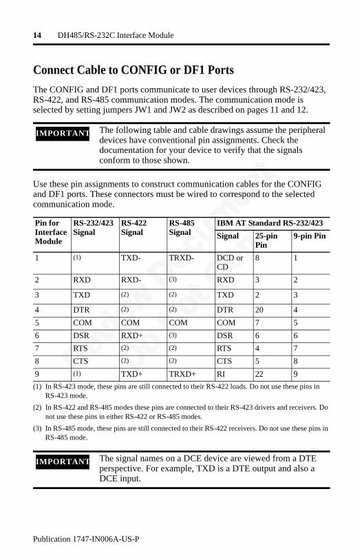
The following illustrations show wiring diagrams for the RS-232/423, RS-422, and RS-485 communications.
NC
RXD
TXD
DTR
COM
DSR
RTS
CTS
NC
1
2
3
4
5
6
7 8
9
CD
TXD
RXD
COM
RI
1
2
3
4
5
6
7 8
9
8
3
2
20
7
6
4 5
22
DTR
DSR
RTS
CTS
NC
RXD
TXD
DTR
COM
DSR
RTS
CTS
NC
1
2
3
4
5
6
7 8
9
CD
TXD
RXD
COM
RI
1
2
3
4
5
6
7 8
9
8
3
2
20
7
6
4 5
22
DTR
DSR
RTS
CTS
RS-232/423 DTE to DCE(Non-Modem Hardware Handshake to Interface Module Peripheral
9-Pin
25-Pin
Interface Module Peripheral9-Pin
25-Pin
RS-232/423 DTE to DCE(Modem Hardware Handshake to DCE)
(DTE)
(DCE)(DTE)
(DCE)

Revie
w Doc
umen
t
Do Not
Copy
16 DH485/RS-232C Interface Module
Publication 1747-IN006A-US-P
NC
RXD
TXD
DTR
COM
DSR
RTS
CTS
NC
1
2
3
4
5
6
7 8
9
1
2
3
4
5
6
7 8
9
8
3
2
20
7
6
4 5
22
CD
COM
RI
RXD
TXD
DTR
DSR
RTS
CTS
NC
RXD
TXD
DTR
COM
DSR
RTS
CTS
NC
1
2
3 4
5
6
7 8 9
1
2
3 4
5
6
7 8 9
8
3
2 20
7
6
4 5 22
CD
COM
RI
RXD
TXD
DTR
DSR
RTS
CTS
RS-232/423 DTE to DCE(No Handshake to DCE)
Interface Peripheral9-Pin
25-Pin
Interface Peripheral9-Pin
25-Pin
RS-232/423 DTE to DCE(Soft or No Handshake to DCE)
(DTE)
(DTE)(DTE)
(DCE)
(1)
(1)
(1)
(1)
(1) Connect DSR to DTR and CTSto RTS when using devices that cannot disable their hardware handshaking.
(1) Connect DSR to DTR and CD, and CTS to RTS when using devices that cannot disable their hardware handshaking.
Revie
w Doc
umen
t
Do Not
Copy
17 DH485/RS-232C Interface Module
Publication 1747-IN006A-US-P
TXD-
RXD-
COM
RXD+
TXD+
1
2
3 4
5
6
7 8 9
RXD-
TXD-
COM
TXD+
RXD+
TRXD-
COM
TRXD+
1
2
3 4
5
6
7 8 9
TRXD-
COM
TRXD+
RS-422
RS-485
Interface Module
Interface Module
Peripheral
Peripheral
(DTE)
(DTE)
Revie
w Doc
umen
t
Do Not
Copy
18 DH485/RS-232C Interface Module
Publication 1747-IN006A-US-P
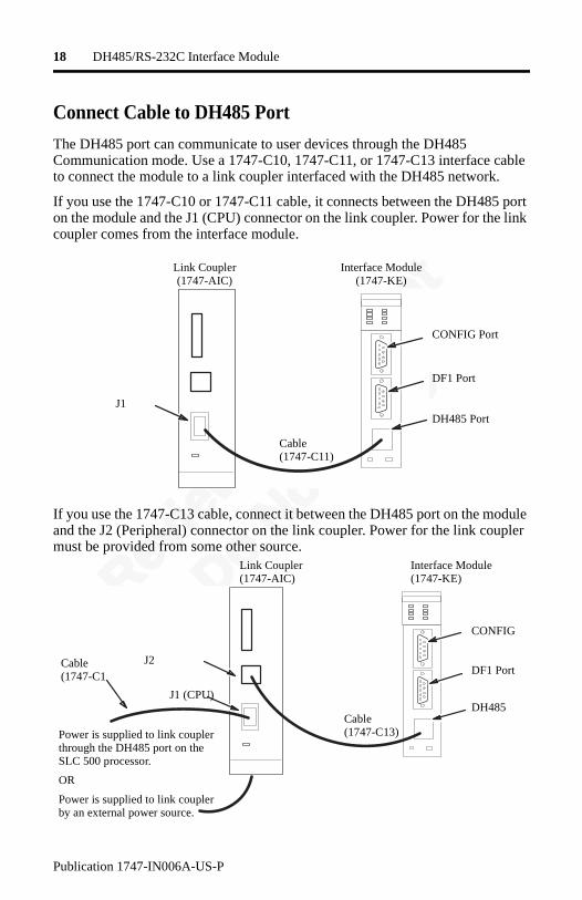
Connect Cable to DH485 Port
The DH485 port can communicate to user devices through the DH485 Communication mode. Use a 1747-C10, 1747-C11, or 1747-C13 interface cable to connect the module to a link coupler interfaced with the DH485 network.
If you use the 1747-C10 or 1747-C11 cable, it connects between the DH485 port on the module and the J1 (CPU) connector on the link coupler. Power for the link coupler comes from the interface module.
If you use the 1747-C13 cable, connect it between the DH485 port on the module and the J2 (Peripheral) connector on the link coupler. Power for the link coupler must be provided from some other source.
Link Coupler(1747-AIC)
Interface Module(1747-KE)
CONFIG Port
DF1 Port
DH485 PortJ1
Cable(1747-C11)
Link Coupler(1747-AIC)
Interface Module(1747-KE)
CONFIG
DF1 Port
DH485 Cable(1747-C13)
J2
J1 (CPU)
Cable(1747-C1
Power is supplied to link coupler through the DH485 port on the SLC 500 processor.
OR
Power is supplied to link coupler by an external power source.
Revie
w Doc
umen
t
Do Not
Copy
19 DH485/RS-232C Interface Module
Publication 1747-IN006A-US-P
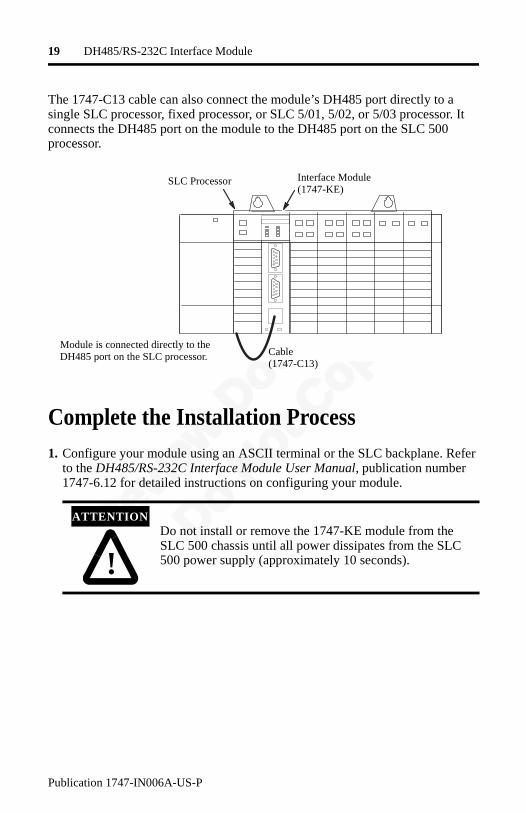
The 1747-C13 cable can also connect the module’s DH485 port directly to a single SLC processor, fixed processor, or SLC 5/01, 5/02, or 5/03 processor. It connects the DH485 port on the module to the DH485 port on the SLC 500 processor.
Complete the Installation Process1. Configure your module using an ASCII terminal or the SLC backplane. Refer
to the DH485/RS-232C Interface Module User Manual, publication number 1747-6.12 for detailed instructions on configuring your module.
!
ATTENTIONDo not install or remove the 1747-KE module from the SLC 500 chassis until all power dissipates from the SLC 500 power supply (approximately 10 seconds).
Interface Module(1747-KE)
SLC Processor
Cable(1747-C13)
Module is connected directly to the DH485 port on the SLC processor.
Revie
w Doc
umen
t
Do Not
Copy
20 DH485/RS-232C Interface Module
Publication 1747-IN006A-US-P
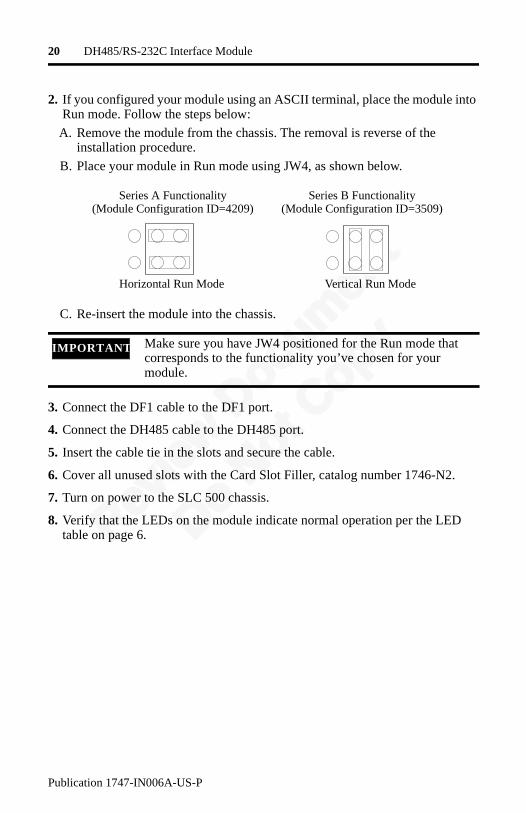
2. If you configured your module using an ASCII terminal, place the module into Run mode. Follow the steps below:
A. Remove the module from the chassis. The removal is reverse of the installation procedure.
B. Place your module in Run mode using JW4, as shown below.
C. Re-insert the module into the chassis.
3. Connect the DF1 cable to the DF1 port.
4. Connect the DH485 cable to the DH485 port.
5. Insert the cable tie in the slots and secure the cable.
6. Cover all unused slots with the Card Slot Filler, catalog number 1746-N2.
7. Turn on power to the SLC 500 chassis.
8. Verify that the LEDs on the module indicate normal operation per the LED table on page 6.
IMPORTANT Make sure you have JW4 positioned for the Run mode that corresponds to the functionality you’ve chosen for your module.
Series A Functionality(Module Configuration ID=4209)
Series B Functionality(Module Configuration ID=3509)
Horizontal Run Mode Vertical Run Mode

Revie
w Doc
umen
t
Do Not
Copy
DH485/RS-232C Interface Module 21
Publication 1747-IN006A-US-P
Specifications
Power Consumption
Environmental Conditions
Voltage Current Required
5V dc .150 A
24V dc .040 A (1) (2)
(1) If the 1747-AIC Link Coupler is connected to the 1747-KE module with a 1747-C11 cable, then the link coupler draws its power (0.085 A at 24V dc) through the module. Add this to the listed current requirements for the 1747-KE module.
(2) If the 1747-AIC Link Coupler is connected to the 1747-KE module with a 1747-C13 cable, then power for the link coupler comes from either an SLC 500 processor or an external power supply. Refer to the documentation provided with the link coupler. Module current requirements remain as listed.
IMPORTANT The 1747-KE module requires both 5V dc and 24V dc power from the SLC backplane. The power consumption of the module must be taken into consideration when planning your SLC 500 system. Refer to the documentation supplied with your SLC 500 fixed or modular controller for additional information on power supplies and current requirements.
Condition Range
Operating temperature 0°C to 60°C (32°F to 140°F)
Storage temperature -40°C to 85°C (-40°F to 185°F)
Relative humidity 5% to 95% (non-condensing)
Certification • C-UL certified
• C-UL Class 1, Division 2 Groups A, B, C, D certified
• UL listed
• CE compliant for all applicable directives

Revie
w Doc
umen
t
Do Not
Copy
22 DH485/RS-232C Interface Module
Publication 1747-IN006A-US-P
Port Isolation
Real Time Clock/Calendar Accuracy
Maximum Communication Distances
Port Isolation Isolation Voltage
CONFIG Backplane to Port 500V dc
DF1 Backplane to Port 500V dc
CONFIG and DF1 CONFIG to DF1 500V dc
IMPORTANT The DH485 Port is not isolated.
Specification Range
Accuracy ±1 minute/month at +25 C
+0, -6 minutes/month at +60°C
Communication Maximum Distance Allowed in meters (feet)
Rate (bps) RS-232 RS-423 RS-422 RS-485
300 15 (50) 1230 (4000) 1230 (4000) 1230 (4000)
600 15 (50) 920 (3000) 1230 (4000) 1230 (4000)
1200 15 (50) 770 (2500) 1230 (4000) 1230 (4000)
2400 15 (50) 502 (1650) 1230 (4000) 1230 (4000)
4800 15 (50) 245 (800) 1230 (4000) 1230 (4000)
9600 15 (50) 120 (400) 1230 (4000) 1230 (4000)
19200 15 (50) 60 (200) 1230 (4000) 1230 (4000)
IMPORTANT When communicating in RS-232 mode, use the RS-423 jumper settings.
When communicating in RS-423 mode, use RS-423 or compatible receivers.

Revie
w Doc
umen
t
Do Not
Copy
DH485/RS-232C Interface Module 23
Publication 1747-IN006A-US-P
Notes:

Revie
w Doc
umen
t
Do Not
Copy
Publication 1747-IN006A-US-P - February 2000 40072-082-01 (A)© 2000 Rockwell International Corporation. Printed in the U.S.A.
SLC 500 is a trademark of Rockwell Automation.

![Instruction Manual for Ku-band GaN 25W BUC [NJT8370 series] · 2019-03-03 · * Pin G: RS-232C TxD and Pin H: RS-232C RxD are available for only RS-232C Interface M&C models. * Do](https://static.fdocuments.us/doc/165x107/5e98d9fb511fe222e63bf374/instruction-manual-for-ku-band-gan-25w-buc-njt8370-series-2019-03-03-pin-g.jpg)


![SR5001 RS-232C Control Specification...SR5001 RS-232C Control Specification Page: 3 / 20 Document Version [1.0] Company Restricted 1. Introduction 1-1. Purpose This document was written](https://static.fdocuments.us/doc/165x107/5f85ee197380c119a96e9428/sr5001-rs-232c-control-specification-sr5001-rs-232c-control-specification-page.jpg)


![SR7001 RS-232C Control Specification - us.marantz.com · SR7001 RS-232C Control Specification Page: 4 / 19 Document Version [1.0] Company Restricted 3. Detailed Description The interface](https://static.fdocuments.us/doc/165x107/5ce7286488c993915f8c23a5/sr7001-rs-232c-control-specification-us-sr7001-rs-232c-control-specification.jpg)