DG0598: SmartFusion2 Dual-Axis Motor Control Starter Kit ...€¦ · SmartFusion2 Dual-Axis Motor...
37
January 2016 SmartFusion2 Dual-Axis Motor Control Starter Kit DG0598 Demo Guide
Transcript of DG0598: SmartFusion2 Dual-Axis Motor Control Starter Kit ...€¦ · SmartFusion2 Dual-Axis Motor...

January 2016
SmartFusion2 Dual-Axis Motor ControlStarter Kit
DG0598 Demo Guide

SmartFusion2 Dual-Axis Motor Control Starter Kit
Revision History
Confidentiality StatusThis is a non-confidential document.
Date Revision Change
14 January 2016 5 Fifth release
03 November 2015 4 Fourth release
15 July 2015 3 Third release
4 May 2015 2 Second release
19 February 2015 1 First release

DG0598: SmartFusion2 Dual-Axis Motor Control Starter Kit Demo Guide
Revision 5 3
Table of Contents
Preface . . . . . . . . . . . . . . . . . . . . . . . . . . . . . . . . . . . . . . . . . . . . . . . . . . . . . . . . . . . . . . . . . . . . . . . . . . . . 4About this document . . . . . . . . . . . . . . . . . . . . . . . . . . . . . . . . . . . . . . . . . . . . . . . . . . . . . . . . . . . . . . . . . . . . . . . . 4
Intended Audience . . . . . . . . . . . . . . . . . . . . . . . . . . . . . . . . . . . . . . . . . . . . . . . . . . . . . . . . . . . . . . . . . . . . . . . . . . 4
References . . . . . . . . . . . . . . . . . . . . . . . . . . . . . . . . . . . . . . . . . . . . . . . . . . . . . . . . . . . . . . . . . . . . . . . . . . . . . . . . 4Microsemi Publications . . . . . . . . . . . . . . . . . . . . . . . . . . . . . . . . . . . . . . . . . . . . . . . . . . . . . . . . . . . . . . . . . . . . . . . . . . . . . . 4
SmartFusion2 Dual-Axis Motor Control Starter Kit . . . . . . . . . . . . . . . . . . . . . . . . . . . . . . . . . . . . . . . . . . . 5Introduction . . . . . . . . . . . . . . . . . . . . . . . . . . . . . . . . . . . . . . . . . . . . . . . . . . . . . . . . . . . . . . . . . . . . . . . . . . . . . . . 5
Design Requirements . . . . . . . . . . . . . . . . . . . . . . . . . . . . . . . . . . . . . . . . . . . . . . . . . . . . . . . . . . . . . . . . . . . . . . . 5
Demo Design . . . . . . . . . . . . . . . . . . . . . . . . . . . . . . . . . . . . . . . . . . . . . . . . . . . . . . . . . . . . . . . . . . . . . . . . . . . . . . 6Introduction . . . . . . . . . . . . . . . . . . . . . . . . . . . . . . . . . . . . . . . . . . . . . . . . . . . . . . . . . . . . . . . . . . . . . . . . . . . . . . . . . . . . . . . 6Demo Design Features . . . . . . . . . . . . . . . . . . . . . . . . . . . . . . . . . . . . . . . . . . . . . . . . . . . . . . . . . . . . . . . . . . . . . . . . . . . . . . 7
Setting Up the Demo Design . . . . . . . . . . . . . . . . . . . . . . . . . . . . . . . . . . . . . . . . . . . . . . . . . . . . . . . . . . . . . . . . . . 7Setting Up the Hardware . . . . . . . . . . . . . . . . . . . . . . . . . . . . . . . . . . . . . . . . . . . . . . . . . . . . . . . . . . . . . . . . . . . . . . . . . . . . . 7Installing the Motor Control GUI . . . . . . . . . . . . . . . . . . . . . . . . . . . . . . . . . . . . . . . . . . . . . . . . . . . . . . . . . . . . . . . . . . . . . . . 8
Running the Demo Design . . . . . . . . . . . . . . . . . . . . . . . . . . . . . . . . . . . . . . . . . . . . . . . . . . . . . . . . . . . . . . . . . . . 17Running the BLDC Motors . . . . . . . . . . . . . . . . . . . . . . . . . . . . . . . . . . . . . . . . . . . . . . . . . . . . . . . . . . . . . . . . . . . . . . . . . . 19Running Stepper Motors . . . . . . . . . . . . . . . . . . . . . . . . . . . . . . . . . . . . . . . . . . . . . . . . . . . . . . . . . . . . . . . . . . . . . . . . . . . . 27
Appendix 1: Jumper Settings . . . . . . . . . . . . . . . . . . . . . . . . . . . . . . . . . . . . . . . . . . . . . . . . . . . . . . . . . . . . . . . . . 30
Appendix 2: Connecting the Motor Terminals . . . . . . . . . . . . . . . . . . . . . . . . . . . . . . . . . . . . . . . . . . . . . . . . . . . . 31BLDC Motor Connections . . . . . . . . . . . . . . . . . . . . . . . . . . . . . . . . . . . . . . . . . . . . . . . . . . . . . . . . . . . . . . . . . . . . . . . . . . . 31Stepper Motor Connections . . . . . . . . . . . . . . . . . . . . . . . . . . . . . . . . . . . . . . . . . . . . . . . . . . . . . . . . . . . . . . . . . . . . . . . . . 32
List of Changes . . . . . . . . . . . . . . . . . . . . . . . . . . . . . . . . . . . . . . . . . . . . . . . . . . . . . . . . . . . . . . . . . . . . . 34Product Support . . . . . . . . . . . . . . . . . . . . . . . . . . . . . . . . . . . . . . . . . . . . . . . . . . . . . . . . . . . . . . . . . . . . 35
Customer Service . . . . . . . . . . . . . . . . . . . . . . . . . . . . . . . . . . . . . . . . . . . . . . . . . . . . . . . . . . . . . . . . . . . . . . . . . 35
Customer Technical Support Center . . . . . . . . . . . . . . . . . . . . . . . . . . . . . . . . . . . . . . . . . . . . . . . . . . . . . . . . . . . 35
Technical Support . . . . . . . . . . . . . . . . . . . . . . . . . . . . . . . . . . . . . . . . . . . . . . . . . . . . . . . . . . . . . . . . . . . . . . . . . 35
Website . . . . . . . . . . . . . . . . . . . . . . . . . . . . . . . . . . . . . . . . . . . . . . . . . . . . . . . . . . . . . . . . . . . . . . . . . . . . . . . . . 35
Contacting the Customer Technical Support Center . . . . . . . . . . . . . . . . . . . . . . . . . . . . . . . . . . . . . . . . . . . . . . . 35Email . . . . . . . . . . . . . . . . . . . . . . . . . . . . . . . . . . . . . . . . . . . . . . . . . . . . . . . . . . . . . . . . . . . . . . . . . . . . . . . . . . . . . . . . . . . 35My Cases . . . . . . . . . . . . . . . . . . . . . . . . . . . . . . . . . . . . . . . . . . . . . . . . . . . . . . . . . . . . . . . . . . . . . . . . . . . . . . . . . . . . . . . 36Outside the U.S. . . . . . . . . . . . . . . . . . . . . . . . . . . . . . . . . . . . . . . . . . . . . . . . . . . . . . . . . . . . . . . . . . . . . . . . . . . . . . . . . . . 36
ITAR Technical Support . . . . . . . . . . . . . . . . . . . . . . . . . . . . . . . . . . . . . . . . . . . . . . . . . . . . . . . . . . . . . . . . . . . . . 36

Revision 5 4
Preface
About this documentThis demo is for Microsemi® SmartFusion®2 system-on-chip (SoC) field programmable gate array (FPGA) dual-axis motor control starter kit. It provides instructions about how to use the corresponding reference design.
Intended AudienceSmartFusion2 dual-axis motor control starter kits are used by:
• FPGA designers
• Embedded designers
• System-level designers
References
Microsemi PublicationsFor a complete and up-to-date listing of motor control documentation, visit: http://www.microsemi.com/applications/motor-control
Revision 5 5
SmartFusion2 Dual-Axis Motor Control Starter Kit
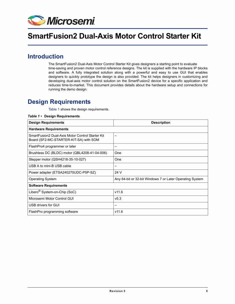
IntroductionThe SmartFusion2 Dual-Axis Motor Control Starter Kit gives designers a starting point to evaluate time-saving and proven motor control reference designs. The kit is supplied with the hardware IP blocksand software. A fully integrated solution along with a powerful and easy to use GUI that enablesdesigners to quickly prototype the design is also provided. The kit helps designers in customizing anddeveloping dual-axis motor control solution on the SmartFusion2 device for a specific application andreduces time-to-market. This document provides details about the hardware setup and connections forrunning the demo design.
Design RequirementsTable 1 shows the design requirements.
Table 1 • Design Requirements
Design Requirements Description
Hardware Requirements
SmartFusion2 Dual-Axis Motor Control Starter Kit Board (SF2-MC-STARTER-KIT-SA) with SOM
–
FlashPro4 programmer or later –
Brushless DC (BLDC) motor (QBL4208-41-04-006) One
Stepper motor (QSH4218-35-10-027) One
USB A to mini-B USB cable –
Power adapter (ETSA240270UDC-P5P-SZ) 24 V
Operating System Any 64-bit or 32-bit Windows 7 or Later Operating System
Software Requirements
Libero® System-on-Chip (SoC) v11.6
Microsemi Motor Control GUI v5.3
USB drivers for GUI –
FlashPro programming software v11.6

SmartFusion2 Dual-Axis Motor Control Starter Kit
6 Revision 5
Demo Design
IntroductionThe demo design files are available for downloading from the following path in the Microsemi website:http://soc.microsemi.com/download/rsc/?f=m2s_dg0598_liberov11p6_pf
The demo design files include:
• Programming File
• readme.txt
Figure 1 shows the top-level structure of the design files. For further details, refer to the readme.txt file.
The GUI installers are available for downloading from the following path in the Microsemi website:http://soc.microsemi.com/download/rsc/?f=m2s_dg0598_liberov11p6_gui
The GUI installers files include:
• GUI installer
• readme.txt
Figure 2 shows the top-level structure of the GUI installer. For further details, refer to the readme.txt file.
Figure 1 • Demo Design Files Top-Level Structure
Figure 2 • GUI Installer Top-Level Structure

DG0598: SmartFusion2 Dual-Axis Motor Control Starter Kit Demo Guide
Revision 5 7
Demo Design FeaturesThe demo design runs:
• A single permanent-magnet synchronous motor (PMSM) using sensorless field oriented control (FOC) algorithm
• A single stepper motor using the micro-stepping algorithm
The GUI provided with the demo is used to configure and control the motors. The GUI can also plotcertain debug variables, and display motor speed and current values.
Setting Up the Demo DesignThis section has the following subsections:
• Setting Up the Hardware
• Installing the Motor Control GUI
• GUI Driver Configuration
Setting Up the HardwareFigure 3 shows the hardware setup for one BLDC motor in Sensorless FOC and a stepper motor in FOC.
Connecting the Board 1. Connect the 24 V power supply to J12 connector.
2. Connect the BLDC motor (QBL4208-41-04-006) to J2 connector on the board as shown in Figure 3.
– Black wire - U-Phase of the motor
– Red wire - V-Phase of the motor
– Yellow wire - W-Phase of the motor
Figure 3 • SmartFusion2 Dual Axis Motor Control Demo Hardware Setup

SmartFusion2 Dual-Axis Motor Control Starter Kit
8 Revision 5
3. Connect the Stepper motor (QSH4218-35-10-027) to J3 connector on the board as shown in Figure 3 on page 7.
– Black wire - A1 of the motor to be connected to PHS4
– Green wire - A2 of the motor to be connected to W
– Red wire - B1 of the motor to be connected to V
– Blue wire - B2 of the motor to be connected to U
4. Set the required jumpers on the board. For information on jumper settings, refer to Table 2 on page 30.
5. Switch ON the SW3 power supply switch on the board.
6. Connect the FlashPro JTAG to the FP header.
7. Open FlashPro software and program the STAPL file (SK2ABLSLST10_5_2.stp).
8. Power cycle the board using SW3.
Install the motor control GUI as described in the following section.
Installing the Motor Control GUIThe following steps describe how to install the Motor Control GUI:
1. From the downloaded folder, open the \m2s_dg0598_liberov11p6_gui\GUI_5_3 folder and run setup.exe.
2. Click Yes for any message from User Account Control. Setup window is displayed with the default locations.
3. Click Next.
– Accept the license agreement and click Next.
– Confirm the installation location in the installation dialog box and click Next.
A progress bar appears that shows the progress of the installation. On successful installation, the following message is displayed: Installation Complete.
4. Click Finish to exit the installation wizard.
5. Restart the Host PC.

DG0598: SmartFusion2 Dual-Axis Motor Control Starter Kit Demo Guide
Revision 5 9
Check the device manager to see if the USB drivers are already configured on the Host machine. Tocheck if the drivers are configured correctly, after ensuring that the hardware is powered ON andconnected to the Host PC using USB cable (J17 connector on board). Check if NI-VISA USB devicesappears in the device manager as shown in Figure 4. If they are configured, skip to "Running the DemoDesign" section on page 17.
Figure 4 • Identifying the SmartFusion2 Motor Control Kit USB Driver

SmartFusion2 Dual-Axis Motor Control Starter Kit
10 Revision 5
GUI Driver ConfigurationThe following steps describe how to install the GUI driver on the Host PC that has Windows 7 or aboveinstalled. The downloaded programming file must be programmed on the board before proceeding fordriver installation.
1. Connect the Host PC to the J17 connector on the SmartFusion2 Motor Control Kit using the USB A to mini-B USB cable.
2. Connect the power adapter to the kit and switch ON SW3 switch.
3. Open Device Manager of the Host PC and select USB Input Device under Human Interface Devices as shown in Figure 5.
Figure 5 • Device Manager

DG0598: SmartFusion2 Dual-Axis Motor Control Starter Kit Demo Guide
Revision 5 11
4. Right-click on the USB Input Device and select Properties as shown in Figure 6.
Figure 6 • Installing the USB Driver - Opening the Properties Window

SmartFusion2 Dual-Axis Motor Control Starter Kit
12 Revision 5
Figure 7 shows the USB Input Device Properties window.
5. In the Details tab, select Hardware Ids under Property.
6. Select the appropriate VID number under Value and click OK. The VID number must have 1514, as shown in Figure 7.
Figure 7 • Selecting the Right VID Number in the Properties Window
DG0598: SmartFusion2 Dual-Axis Motor Control Starter Kit Demo Guide
Revision 5 13
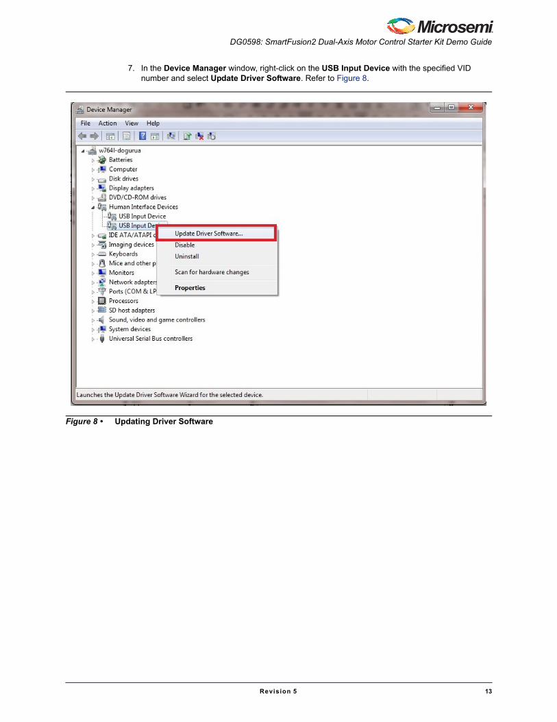
7. In the Device Manager window, right-click on the USB Input Device with the specified VID number and select Update Driver Software. Refer to Figure 8.
Figure 8 • Updating Driver Software
SmartFusion2 Dual-Axis Motor Control Starter Kit
14 Revision 5
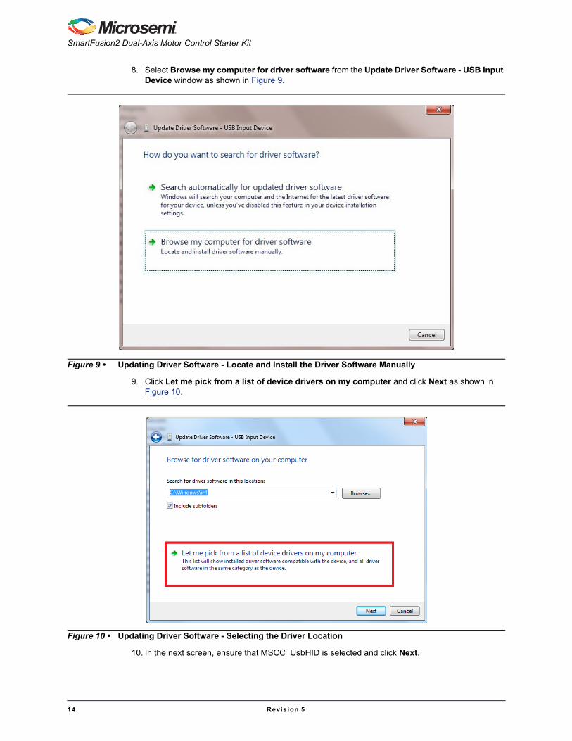
8. Select Browse my computer for driver software from the Update Driver Software - USB Input Device window as shown in Figure 9.
9. Click Let me pick from a list of device drivers on my computer and click Next as shown in Figure 10.
10. In the next screen, ensure that MSCC_UsbHID is selected and click Next.
Figure 9 • Updating Driver Software - Locate and Install the Driver Software Manually
Figure 10 • Updating Driver Software - Selecting the Driver Location

DG0598: SmartFusion2 Dual-Axis Motor Control Starter Kit Demo Guide
Revision 5 15
11. A pop up window appears as shown in Figure 12. Click Install.
Figure 11 • Model Selection
Figure 12 • Windows Security Dialog
SmartFusion2 Dual-Axis Motor Control Starter Kit
16 Revision 5
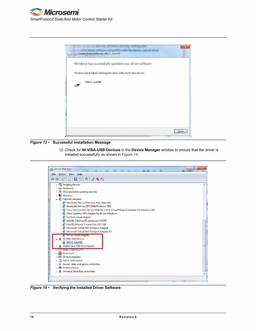
12. Check for NI-VISA-USB Devices in the Device Manager window to ensure that the driver is installed successfully as shown in Figure 14.
Figure 13 • Successful Installation Message
Figure 14 • Verifying the Installed Driver Software

DG0598: SmartFusion2 Dual-Axis Motor Control Starter Kit Demo Guide
Revision 5 17
Running the Demo Design1. After installing the GUI, go to Start menu and select SF2 Dual Axis Motor Control GUI to open
the GUI as shown in Figure 15.
Figure 15 • Launching the SmartFusion2 Dual-Axis Motor Control GUI

SmartFusion2 Dual-Axis Motor Control Starter Kit
18 Revision 5
2. In the SmartFusion2 Motor Control GUI, select the USB device with VID 0x1514 and PID 0x2015 (USB0::0x1514::0x2015..) from the USB DEVICE drop-down list.
3. Click Connect as shown in Figure 16.
On successful connection, the Connect button (highlighted in Figure 16) turns to green.
Figure 16 • SmartFusion2 Motor Control GUI - Launch Window

DG0598: SmartFusion2 Dual-Axis Motor Control Starter Kit Demo Guide
Revision 5 19
Running the BLDC MotorsUse the GET and SET options to modify or verify the motor speed, motor ramp rate, current and speedloop PI controller parameters, and angle correction PI parameters. Click Configure to invoke theConfigure Motor Parameters window.
The PI controller parameters (Kp, Ki values) can be modified using the Configure Motor Parameterswindow shown in Figure 18 on page 20.
Figure 18 on page 20 shows the Configure Motor Parameters window for BLDC. It allows you to changePI controller constants, startup mode, soft stop setting, Closed Loop Speed threshold, Open LoopCurrent, and Voltage.
Figure 17 • SmartFusion2 Motor Control GUI - BLDC Motor Screen
SmartFusion2 Dual-Axis Motor Control Starter Kit
20 Revision 5
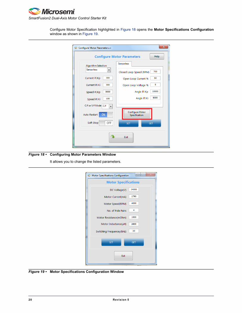
Configure Motor Specification highlighted in Figure 18 opens the Motor Specifications Configurationwindow as shown in Figure 19.
It allows you to change the listed parameters.
Figure 18 • Configuring Motor Parameters Window
Figure 19 • Motor Specifications Configuration Window

DG0598: SmartFusion2 Dual-Axis Motor Control Starter Kit Demo Guide
Revision 5 21
– To modify a parameter, change the required field and click SET.
– To check the data in the hardware corresponding to each parameter, click GET.
– To run the motor, click RUN and to stop the motor, click STOP.
4. Click Run All to run all the motors and click Stop All to stop all the running motors. These buttons are highlighted in Figure 20.
In the event of a fault occurrence, it is indicated in the indicator above the Clear Fault button. To clear a Fault, click Clear Fault highlighted in Figure 20.
– Click Motor Direction to set the motor direction. This button also indicates the current motor direction.
Figure 20 • SmartFusion2 Motor Control GUI - Run or Stop All Motors

SmartFusion2 Dual-Axis Motor Control Starter Kit
22 Revision 5
5. The GUI automatically plots waveforms when motor starts running. The plotting can be paused by clicking the pause button highlighted in Figure 21.
Figure 21 • SmartFusion2 Motor Control GUI - Start Plotting
DG0598: SmartFusion2 Dual-Axis Motor Control Starter Kit Demo Guide
Revision 5 23
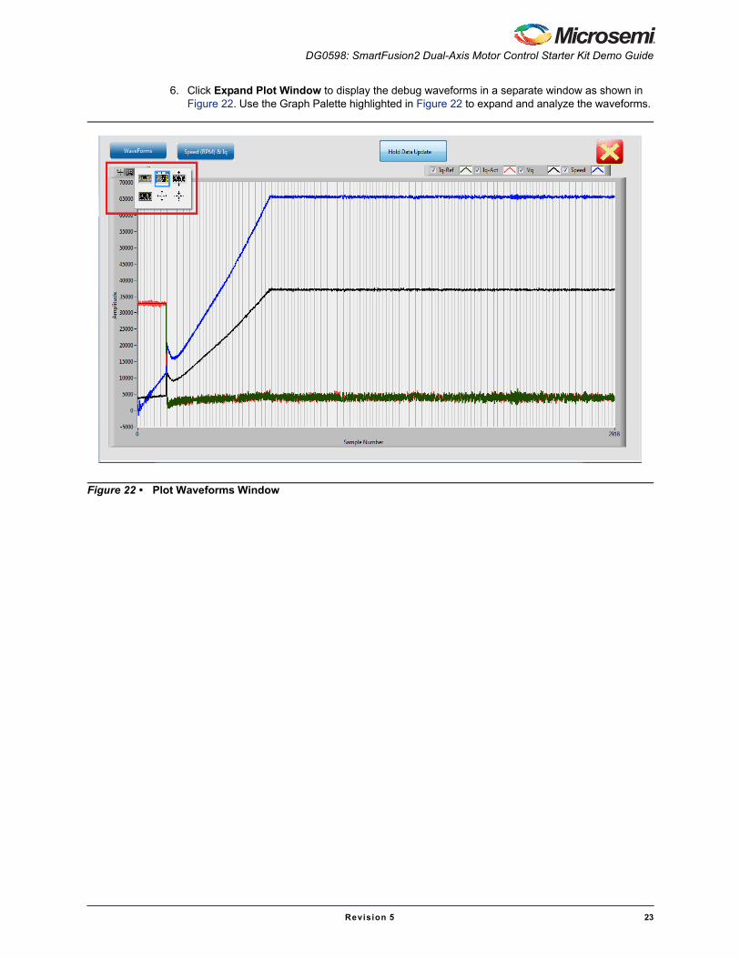
6. Click Expand Plot Window to display the debug waveforms in a separate window as shown in Figure 22. Use the Graph Palette highlighted in Figure 22 to expand and analyze the waveforms.
Figure 22 • Plot Waveforms Window
SmartFusion2 Dual-Axis Motor Control Starter Kit
24 Revision 5
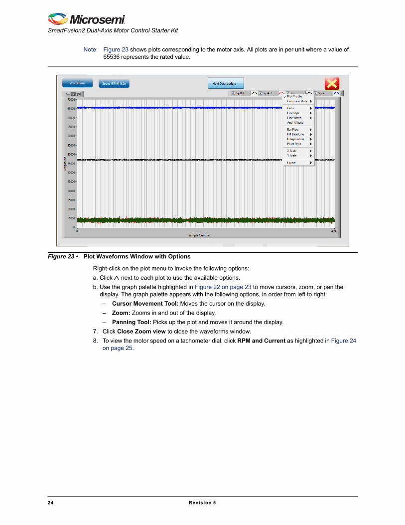
Note: Figure 23 shows plots corresponding to the motor axis. All plots are in per unit where a value of 65536 represents the rated value.
Right-click on the plot menu to invoke the following options:
a. Click next to each plot to use the available options.
b. Use the graph palette highlighted in Figure 22 on page 23 to move cursors, zoom, or pan the display. The graph palette appears with the following options, in order from left to right:
– Cursor Movement Tool: Moves the cursor on the display.
– Zoom: Zooms in and out of the display.
– Panning Tool: Picks up the plot and moves it around the display.
7. Click Close Zoom view to close the waveforms window.
8. To view the motor speed on a tachometer dial, click RPM and Current as highlighted in Figure 24 on page 25.
Figure 23 • Plot Waveforms Window with Options

DG0598: SmartFusion2 Dual-Axis Motor Control Starter Kit Demo Guide
Revision 5 25
Figure 24 • SmartFusion2 Motor Control GUI - Displaying Speed and Current

SmartFusion2 Dual-Axis Motor Control Starter Kit
26 Revision 5
9. Click Save Waveform as shown in Figure 25 to save the current waveform in the GUI as a .tdms file. The saved waveform can be reloaded by using the Load Waveform option and loading the .tdms file.
Figure 25 • SmartFusion2 Motor Control GUI - Saving and Loading Waveforms

DG0598: SmartFusion2 Dual-Axis Motor Control Starter Kit Demo Guide
Revision 5 27
Running Stepper MotorsThis design runs stepper motors in:
• Speed Mode
• Position Mode
The Continuous Mode is selected by default.
Speed ModeIn Speed mode, the motor rotates continuously in a speed that is set. Click Stop to stop the runningmotor.
1. Click Stepper to select the stepper motor.
2. Verify that the Speed mode option is selected. Figure 26 shows the SmartFusion2 Motor Control GUI - Stepper motor window.
3. Click GET to see the current parameters. Click Configure to open a list of configurable parameters. Refer to Figure 26.
– Click Reset to reset all the stepper parameters to their default values in the GUI, but it does not enter them into the system.
– Click SET to enter the current values into the system.
4. Click RUN to run the motor with the current parameters.
5. Select step resolution value from the Step Resolution drop-down list.
6. Enter a speed value between 1 and 200 RPM in Speed (RPM) and then click SET.
Notes:
– It is not necessary to stop the motor to change motor speed or the step resolution.
– To change the direction of the motor, click Motor Direction.
Figure 26 • SmartFusion2 Motor Control GUI - Stepper Motor Window

SmartFusion2 Dual-Axis Motor Control Starter Kit
28 Revision 5
7. To increase motor torque, increase the current reference and click SET.
Caution: Increasing the current scaling value increases the motor current and the motor can get heated if it is run for a long time.
8. Click STOP to stop the motor.
Position ModeIn Position mode, the motor rotates and stops as per the command steps. It rotates in a speed that is set.
1. Select Position mode option and click SET.
2. Enter the required (absolute) position in Command Steps.
a. The motor provided with the kit has a step number of 200 by default. To run the motor through one revolution, enter 200 in Command Steps.
b. Click SET.
c. Click RUN. The motor runs through the specified number of steps.
– In the Position mode, the motor moves through a fixed number of steps after which the motor stops rotating, but remains energized.
– To move to a different position, enter the new position and click SET.
– Click STOP to de-energize the motor. When the motor is de-energized, the current position is lost.
Plotting debug parameters by clicking Plot Waveforms, displays Id PI output as plot 0, d-axis motor current (Id) as plot 1, the number of steps moved (step count) as plot 2, and the angle generated as plot 3. Figure 27 shows the GUI in position mode.
The motor runs at the specified speed through the number of steps.
Figure 27 • SmartFusion2 Motor Control GUI - Stepper Motor in Position Mode

DG0598: SmartFusion2 Dual-Axis Motor Control Starter Kit Demo Guide
Revision 5 29
3. Click Configure to open the Configure Stepper Motor Parameters window as shown in Figure 28.
4. Click STOP to stop the motor/de-energize the motor.
5. Click EXIT to exit the SmartFusion2 Motor Control GUI.
Figure 28 • Configure Stepper Motor Parameters Window

SmartFusion2 Dual-Axis Motor Control Starter Kit
30 Revision 5
Appendix 1: Jumper SettingsTable 2 shows all the jumpers that are required to set on the SmartFusion2 Starter Kit board.
Table 2 • Jumper Settings on the SmartFusion2 Starter Kit Board
Jumper FunctionDefault Settings Notes
Power Supply
J23 SOM power source 1-3 Closed On-board power to SOM
J22 JTAG Mode 3-4 Closed JTAG VPP to 3.3 V
J7, J13 Encoder - Single Ended selection Open To be set for single ended encoder
J8 Encoder – Differential selection Open To be set for differential encoder
J19 Shunt resistor for power measurement Open Voltage can be measured across shunt
J11 Encoder Open Port to connect encoder
Note: Figure 29 shows the jumper settings on the SmartFusion2 Starter Kit.
Figure 29 • Jumpers on SmartFusion2 Starter Kit

DG0598: SmartFusion2 Dual-Axis Motor Control Starter Kit Demo Guide
Revision 5 31
Appendix 2: Connecting the Motor Terminals
BLDC Motor ConnectionsThe following steps describe how to connect to the BLDC motor:
1. Identify and isolate the BLDC Motor Terminals (set of 3) and Hall Sensor Terminals (set of 5), as shown in Figure 30. These terminals are tied together.
2. Connect the BLDC Motor Terminals to the three pin plug, as shown in Figure 30.
3. Connect the Hall Sensor Terminals to the five pin plug, as shown in Figure 30.
Figure 30 • Wiring Diagram for BLDC Motor Connectors

SmartFusion2 Dual-Axis Motor Control Starter Kit
32 Revision 5
Stepper Motor ConnectionsThe stepper motor has four terminals. The motor terminals of the stepper motor must be connected tothe four pin plug, as shown in Figure 31.
Figure 31 • Wiring Diagram for Stepper Motor Connectors

Revision 5 34
List of Changes
The following table shows important changes made in this document for each revision.
Date Changes Page
Revision 5(January 2016)
Updated the document for GUI v5.3 release (SAR 75167). NA
Revision 4(October 2015)
Updated the document for GUI v5.2 release (SAR 72926). NA
Updated the document for Libero v11.6 software release (SAR 72926). NA
Revision 3(July 2015)
Added "Appendix 2: Connecting the Motor Terminals" section on page 31 (SAR 69108).
31
Revision 2(May 2015)
Updated Table 2 and added Figure 29 to update jumper settings (SAR 66381). 30 and 30
Revision 1(February 2015)
Initial release. NA

Revision 5 35
Product Support
Microsemi SoC Products Group backs its products with various support services, including CustomerService, Customer Technical Support Center, a website, electronic mail, and worldwide sales offices.This appendix contains information about contacting Microsemi SoC Products Group and using thesesupport services.
Customer ServiceContact Customer Service for non-technical product support, such as product pricing, product upgrades,update information, order status, and authorization.
From North America, call 800.262.1060From the rest of the world, call 650.318.4460Fax, from anywhere in the world, 650.318.8044
Customer Technical Support CenterMicrosemi SoC Products Group staffs its Customer Technical Support Center with highly skilledengineers who can help answer your hardware, software, and design questions about Microsemi SoCProducts. The Customer Technical Support Center spends a great deal of time creating applicationnotes, answers to common design cycle questions, documentation of known issues and various FAQs.So, before you contact us, please visit our online resources. It is very likely we have already answeredyour questions.
Technical SupportFor Microsemi SoC Products Support, visit http://www.microsemi.com/products/fpga-soc/design-support/fpga-soc-support.
WebsiteYou can browse a variety of technical and non-technical information on the Microsemi SoC ProductsGroup home page, at http://www.microsemi.com/products/fpga-soc/fpga-and-soc.
Contacting the Customer Technical Support CenterHighly skilled engineers staff the Technical Support Center. The Technical Support Center can becontacted by email or through the Microsemi SoC Products Group website.
EmailYou can communicate your technical questions to our email address and receive answers back by email,fax, or phone. Also, if you have design problems, you can email your design files to receive assistance.We constantly monitor the email account throughout the day. When sending your request to us, pleasebe sure to include your full name, company name, and your contact information for efficient processing ofyour request.
The technical support email address is [email protected].

Product Support
36 Revision 5
My CasesMicrosemi SoC Products Group customers may submit and track technical cases online by going to MyCases.
Outside the U.S.Customers needing assistance outside the US time zones can either contact technical support via email([email protected]) or contact a local sales office. Visit About Us for sales office listings andcorporate contacts.
ITAR Technical SupportFor technical support on RH and RT FPGAs that are regulated by International Traffic in ArmsRegulations (ITAR), contact us via [email protected]. Alternatively, within My Cases, select Yesin the ITAR drop-down list. For a complete list of ITAR-regulated Microsemi FPGAs, visit the ITAR webpage.

50200598-5/01.16
Microsemi Corporate HeadquartersOne Enterprise, Aliso Viejo,CA 92656 USA
Within the USA: +1 (800) 713-4113 Outside the USA: +1 (949) 380-6100Sales: +1 (949) 380-6136Fax: +1 (949) 215-4996
E-mail: [email protected]
Microsemi Corporation (Nasdaq: MSCC) offers a comprehensive portfolio of semiconductorand system solutions for communications, defense & security, aerospace and industrialmarkets. Products include high-performance and radiation-hardened analog mixed-signalintegrated circuits, FPGAs, SoCs and ASICs; power management products; timing andsynchronization devices and precise time solutions, setting the world’s standard for time; voiceprocessing devices; RF solutions; discrete components; security technologies and scalableanti-tamper products; Ethernet solutions; Power-over-Ethernet ICs and midspans; as well ascustom design capabilities and services. Microsemi is headquartered in Aliso Viejo, Calif., andhas approximately 3,600 employees globally. Learn more at www.microsemi.com.
© 2016 Microsemi Corporation. Allrights reserved. Microsemi and theMicrosemi logo are trademarks ofMicrosemi Corporation. All othertrademarks and service marks are theproperty of their respective owners.
Microsemi makes no warranty, representation, or guarantee regarding the information contained herein orthe suitability of its products and services for any particular purpose, nor does Microsemi assume anyliability whatsoever arising out of the application or use of any product or circuit. The products soldhereunder and any other products sold by Microsemi have been subject to limited testing and should notbe used in conjunction with mission-critical equipment or applications. Any performance specifications arebelieved to be reliable but are not verified, and Buyer must conduct and complete all performance andother testing of the products, alone and together with, or installed in, any end-products. Buyer shall not relyon any data and performance specifications or parameters provided by Microsemi. It is the Buyer'sresponsibility to independently determine suitability of any products and to test and verify the same. Theinformation provided by Microsemi hereunder is provided "as is, where is" and with all faults, and the entirerisk associated with such information is entirely with the Buyer. Microsemi does not grant, explicitly orimplicitly, to any party any patent rights, licenses, or any other IP rights, whether with regard to suchinformation itself or anything described by such information. Information provided in this document isproprietary to Microsemi, and Microsemi reserves the right to make any changes to the information in thisdocument or to any products and services at any time without notice.

Mouser Electronics
Authorized Distributor
Click to View Pricing, Inventory, Delivery & Lifecycle Information: Microsemi:
SF2-MC-STARTER-KIT