
Device manual Ethernet camera for mobile applications UK IP address range (Net ID) of the PC must...
25
Device manual Ethernet camera for mobile applications O2M110 UK 7390715 / 00 03 / 2012
Transcript of Device manual Ethernet camera for mobile applications UK IP address range (Net ID) of the PC must...

Device manualEthernet camera
for mobile applications
O2M110
UK
7390
715
/00
03
/201
2
Contents
1 Safety instructions page 4
2 Functions and features page 52.1 Features at a glance page 5
3 Mounting3.1 Mounting accessories page 63.2 Mounting dimensions page 63.3 Mounting location page 7
4 Electrical connection4.1 Ethernet camera page 8
4.1.1 Ethernet connection page 84.1.2 Interference due to external influences
4.2 PDM360 page 94.3 PC/notebook page 104.4 Connection principle without hub/switch
- One camera at one PDM360 page 11- One camera at one PC/notebook (service mode) page 11
4.5 Connection principle with hub/switch- Several cameras at one PDM360 page 12
5 Operating and display elements page 13
6 Set-up6.1 IP addresses page 14
6.1.1 IP address allocation PDM360 page 146.1.2 IP address allocation cameras page 15
6.2 Parameter setting PDM360 page 196.2.1 Library ifm_Camera_O2M_Vxxxxxx page 196.2.2 Function block CAM_O2M page 196.2.3 Parameter overview page 206.2.4 MODE combinations (1...4 cameras) page 22
7 Technical data7.1 O2M110/111 page 24
8 Maintenance, repair and disposal page 25
9 Approvals/standards page 25
ETHERNET CAMERA O2M110
2

Licences and trademarks
Microsoft®, Windows®, Windows XP® and Windows Vista® are registered trademarks of MicrosoftCorporation. All trademarks and company names are subject to the copyright of the respectivecompanies.
Open source software
This unit contains (maybe modified) Open Source software, which is subject to special licensing terms.For copyright information and licensing terms please refer to: www.ifm.com/int/GNUFor software subject to the GNU General Public License or the GNU Lesser General Public License thesource code can be requested against payment of the copying and shipping costs.
ETHERNET CAMERA O2M110
3
UK

1 Safety instructions
These instructions are part of the device. They contain informationand illustrations about the correct handling of the device and mustbe read before installation or use.
Adhere to the instructions. Non-observance of the instructions, operation whichis not in accordance with use as prescribed below, wrong installation or handlingcan result in serious harm concerning the safety of persons and plant.
These instructions are intended for “authorised” persons according to the EMCand low-voltage directives. The device must only be installed, connected and putinto operation by a qualified electrician.
Disconnect the device externally before handling it. If necessary, also disconnectany independently supplied output load circuits.
If the device is not supplied by the mobile on-board system (12/24 V batteryoperation), it must be ensured that the external voltage is generated andsupplied according to the criteria for safety extra-low voltage (SELV) as thisvoltage is supplied without further measures to the connected controller, thesensors and the actuators.
The wiring of all signals in connection with the SELV circuit of the device mustalso comply with the SELV criteria (safety extra-low voltage, safe electricalseparation from other electric circuits).If the supplied SELV voltage has an external connection to ground (SELV becomesPELV), the responsibility lies with the user and the respective national regulationsfor installation must be complied with. All statements in this manual refer to thedevice the SELV voltage of which is not grounded.
The connection terminals may only be supplied with the signals indicated in thetechnical data and/or on the device label and only the approved accessories ofifm electronic gmbh may be connected.
In case of malfunctions or uncertainties please contact the manufacturer.Tampering with the device can lead to serious risks for the safety of persons andplant. It is not permitted and leads to the exclusion of any liability and warrantyclaims.
ETHERNET CAMERA O2M110
4

2 Functions and features
The Ethernet camera serves for monitoring of areas outside of the field of view inmobile vehicles and utility vehicles. Connection, control and visualisation of theimages is carried out via the process and dialogue module PDM360 with colourdisplay.The camera operates as a server and permanently transmits images to theconnected dialogue module.
Applications are for example:
• Rear area or blind spot monitoring for municipal vehicles• Machine monitoring in construction machinery• Rear view camera on vehicles
2.1 Features at a glance
• Use and operation with process and dialogue module PDM360(version with colour display, art. no. CR1051 from software version V4.3.2)
• Display of up to 4 camera images per PDM360• 10 Mbits/s Ethernet interface
(10Base-T/100Base-TX according to IEEE 802.3/802.3u)• Sealed diecast zinc housing• Protection rating IP 69 K• Regulated lens heating (can be deactivated)• CMOS image sensor, resolution ¼ VGA, 320 x 240 pixels• Angle of aperture 75°• Parameter setting and control functions via the CoDeSys application program,
e.g.:- image mirror function (rear view mode)- rotating- parallel display of several camera images (split screen)- positioning of the images- activation/deactivation- debug mode (adjustable use of the band width of the network)
• Operation display via integrated LED• Mixed display of camera image and PDM360 visualisation elements (text
and/or graphics)
ETHERNET CAMERA O2M110
5
UK

3 Mounting
3.1 Mounting accessories
The device is supplied without mounting accessories.Depending on the intended location and type of mounting the followingmounting accessories are available, for example:
You can find more information about the available accessories at:➔ Data sheet direct ➔ e.g. O2M110 ➔ Accessories
or directly
➔ Data sheet direct ➔ e.g. E2D110
3.2 Mounting dimensions
Mounting is done using two M 4 x L screws.Mounting dimensions of the camera → 7 Technical data (data sheets).
www.ifm-electronic.com
www.ifm-electronic.com
ETHERNET CAMERA O2M110
6
Mounting accessories (examples): Art. no.
Mounting set for shaft Ø 12 mm E2D110(clamp cylinder and fixing element for the types O2D, O2M)
Shaft, straight Ø 12 mm, length 130 mm, M10 E20938
Shaft, angled Ø 12 mm, length 200 mm, M10 E20940
Mounting set for shaft Ø 14 mm E2D112(clamp cylinder and fixing element for the types O2D, O2M)
Shaft, straight Ø 14 mm, length 130 mm, M12 E20939
Shaft, angled Ø 14 mm, length 200 mm, M12 E20941
Mounting accessories (example)
Mounting set for shaft Ø 12 mmart. no. E2D110
Shaft, straight Ø 12 mmE20938
Mounting example

3.3 Mounting location
Mount the camera in front of or above the area to be monitored.The size of the area to be monitored depends on the operating distance:
Device-specific data → 7 Technical data (data sheets).
Note in general
To avoid adverse effects on the image detection, avoid installation in heavilypolluting areas of the machine (e.g. splashing water, tyre abrasion, etc.).
Avoid back light.Do not position lighting elements directly facing the camera lens.
Mount the device in such a way that the cables/connectors are connected frombelow.The connected cables must be provided with a strain relief.
ETHERNET CAMERA O2M110
7
UK
��������
��
�� ��
��������������� ��
�
�
�
�
�
�
���
���
���
���
���
������������
�����
�����
�����
�����
�����
��������� ��� ��width of field of view [m] height of field of view [m]
Operating distance and field of view size (example O2M110)
oper
atin
g di
stan
ce [
m]
Ethernet camera
�
x 1.3
x 2.6
x 3.9
x 5.2
x 6.6

4 Electrical connection
4.1 Ethernet camera
For information about available connectors please go to:➔ Data sheet direct➔ e.g. O2M110 ➔ Accessories
The supply voltage is electrically separated from the housing.
4.1.1 Ethernet connection
Use a shielded CAT5 cable.(STP, Shielded Twisted Pair, according to EIA/TIA-568). Max. length 100 m
Use screened connector housings.Connect the screen of the Ethernet cable to the connector housing.
Avoid transmission problems caused by induction.Do not lay the Ethernet connection cable in parallel to current-carrying cables.Lay supply and signal cables away from the camera using the shortest possibleroute.
4.1.2 Interference due to external influences
Faulty or insufficient radio interference suppressors in electrical equipment, suchas inverters or generators, as well as voltage fluctuations when switching on/offelectric loads may lead to problems with the image transmission.
www.ifm-electronic.com
ETHERNET CAMERA O2M110
8
�
� �
�
� �
��
Supply voltage
Pin Potential
1 8...32 V DC2 n.c.3 0 V4 n.c.
Ethernet
Pin Potential
1 TxD +2 RxD +3 TxD –4 RxD –
M12 supply connection(4-pole, A-coded)
M12 Ethernet(4-pole, D-coded)
Wiring
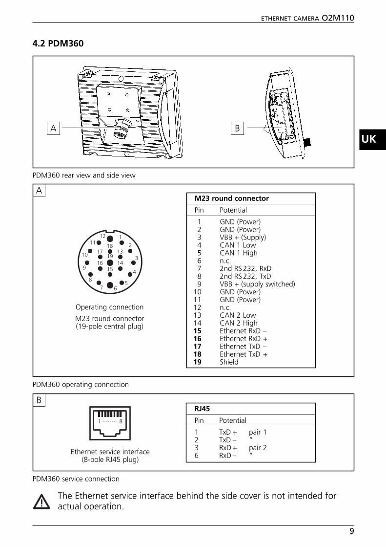
4.2 PDM360
The Ethernet service interface behind the side cover is not intended foractual operation.
ETHERNET CAMERA O2M110
9
UK
RJ45
Pin Potential
1 TxD + pair 12 TxD – ”3 RxD + pair 26 RxD – ”
1 8
1211
10
9
87 6
5
4
3
2
1
18
19
15
17 13
16 14
M23 round connector
Pin Potential
1 GND (Power)2 GND (Power)3 VBB + (Supply)4 CAN 1 Low 5 CAN 1 High 6 n.c.7 2nd RS232, RxD8 2nd RS232, TxD9 VBB + (supply switched)
10 GND (Power)11 GND (Power)12 n.c.13 CAN 2 Low 14 CAN 2 High15 Ethernet RxD –16 Ethernet RxD +17 Ethernet TxD –18 Ethernet TxD +19 Shield
Operating connection
M23 round connector(19-pole central plug)
Ethernet service interface(8-pole RJ45 plug)
A
B
A B
PDM360 rear view and side view
PDM360 operating connection
PDM360 service connection

4.3 PC/notebook
Connection to a PC or to a notebook may be necessary for service purposes (e.g.setting of the IP address).
The configuration of the PC Ethernet interface corresponds to that of the serviceinterface (B) of the PDM360.
Note:The IP address range (Net ID) of the PC must correspond to the IP address rangeof the camera. For the PC/notebook setting is carried out in the Control Panel →Network Connections → Properties
(also see → 6.1.2 IP address allocation Ethernet cameras).
ETHERNET CAMERA O2M110
10
RJ45
Pin Potential
1 TxD + pair 12 TxD – “3 RxD + pair 26 RxD – “
1 8
Ethernet interface(8-pole RJ45 plug)
PC/notebook

4.4 Connection principle without hub/switch
■ One camera at one PDM360■ One camera at one PC/notebook (e.g. service mode)
For further information about the connector go to:➔ Data sheet direct ➔ E11898www.ifm-electronic.com
ETHERNET CAMERA O2M110
11
UK
!�"����#�!���
$��%�& ��������'���
!�"����#�!���
��������'���
('�)�*"���""#
Crosslink cable (example): art. no.
Ethernet connection cable, 2m M12 connector (4-pole, D-coded) – RJ45 (8-pole) E11898
Operating connection:M23 round connector (19-pole)
Service connection:RJ45 plug (8-pole)
Connection:RJ45 plug (8-pole)Ethernet interface
Definition crosslink:crosslink cable = crossover cable = for the direct connectionof network participants
Connection principle without hub/switch
+�$ ,+�$ -.�$ ,.�$ -
+�$ ,+�$ -.�$ ,.�$ -
!�"����#�!���Crosslink cable principle
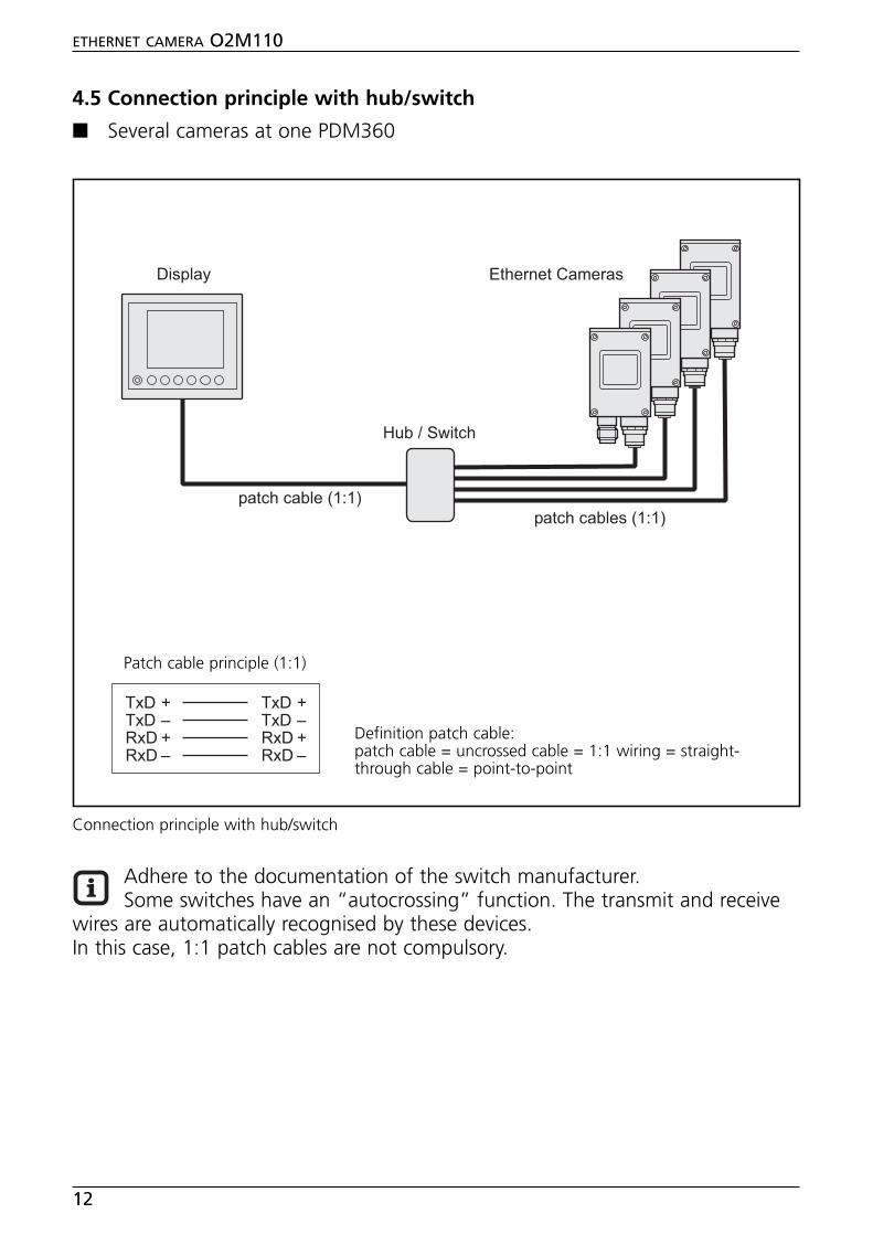
4.5 Connection principle with hub/switch
■ Several cameras at one PDM360
Adhere to the documentation of the switch manufacturer.Some switches have an “autocrossing” function. The transmit and receive
wires are automatically recognised by these devices.In this case, 1:1 patch cables are not compulsory.
ETHERNET CAMERA O2M110
12
%�!��!����/�0�1
$��%�& ��������'����
%�!��!�����/�0�1
23��)�45��!�
Definition patch cable:patch cable = uncrossed cable = 1:1 wiring = straight-through cable = point-to-point
�
Connection principle with hub/switch
+�$ ,+�$ -.�$ ,.�$ -
+�$ ,+�$ -.�$ ,.�$ -
%�!��!����/�0�1Patch cable principle (1:1)

5 Operation display
ETHERNET CAMERA O2M110
13
UKLEDgreen
LED Description
ON supply voltage okcamera ready for operation
OFF no supply voltagepower supply interrupted
Operating indication O2M110/111
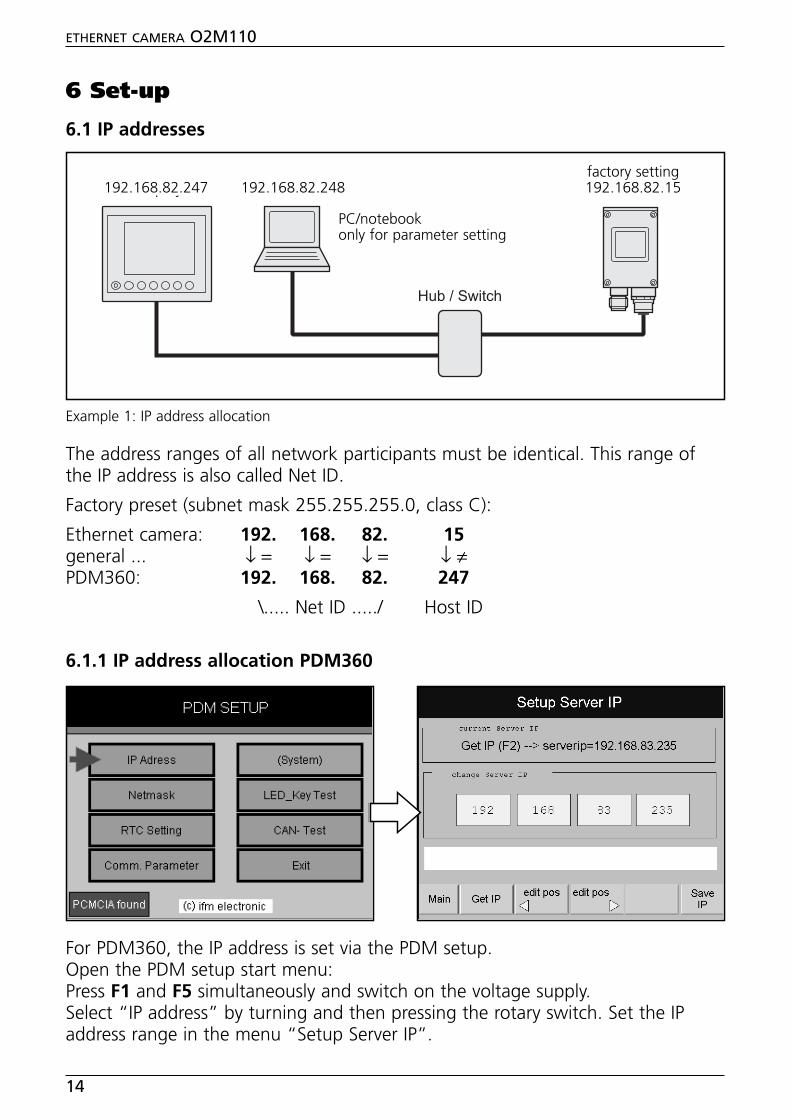
6 Set-up
6.1 IP addresses
The address ranges of all network participants must be identical. This range ofthe IP address is also called Net ID.
Factory preset (subnet mask 255.255.255.0, class C):
Ethernet camera: 192. 168. 82. 15general ... ↓ = ↓ = ↓ = ↓ ≠PDM360: 192. 168. 82. 247
\..... Net ID ...../ Host ID
6.1.1 IP address allocation PDM360
For PDM360, the IP address is set via the PDM setup.Open the PDM setup start menu:Press F1 and F5 simultaneously and switch on the voltage supply.Select “IP address” by turning and then pressing the rotary switch. Set the IPaddress range in the menu “Setup Server IP”.
ETHERNET CAMERA O2M110
14
��������'���$��%�&
23��)�45��!�
('�)�*"���""#
Example 1: IP address allocation
192.168.82.247 192.168.82.248
PC/notebookonly for parameter setting
factory setting 192.168.82.15
PDM360 online help:The online description of the functions, operation and device-specific libraries ofthe PDM360 family is part of the CoDeSys online help.It is also available for download on the internet.
➔ Data sheet direct ➔ e.g. O2M110 ➔ Download/Software
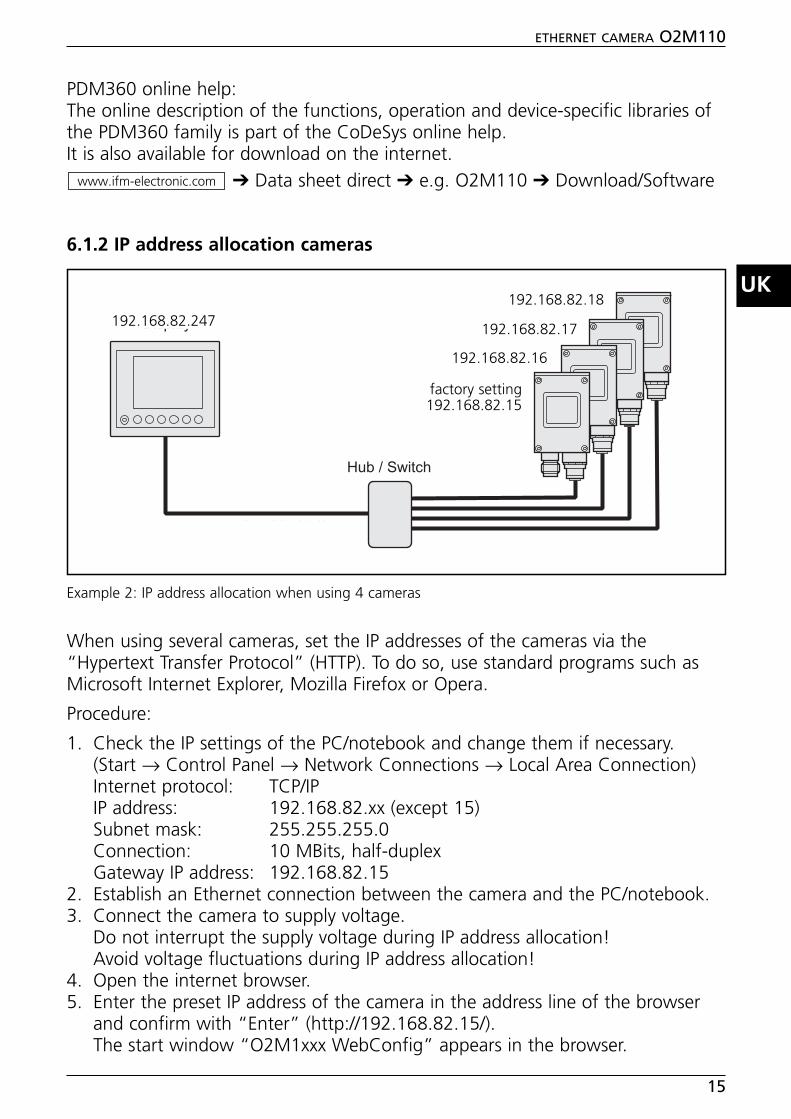
6.1.2 IP address allocation cameras
When using several cameras, set the IP addresses of the cameras via the“Hypertext Transfer Protocol” (HTTP). To do so, use standard programs such asMicrosoft Internet Explorer, Mozilla Firefox or Opera.
Procedure:
1. Check the IP settings of the PC/notebook and change them if necessary.(Start → Control Panel → Network Connections → Local Area Connection)Internet protocol: TCP/IPIP address: 192.168.82.xx (except 15)Subnet mask: 255.255.255.0Connection: 10 MBits, half-duplexGateway IP address: 192.168.82.15
2. Establish an Ethernet connection between the camera and the PC/notebook.3. Connect the camera to supply voltage.
Do not interrupt the supply voltage during IP address allocation!Avoid voltage fluctuations during IP address allocation!
4. Open the internet browser.5. Enter the preset IP address of the camera in the address line of the browser
and confirm with “Enter” (http://192.168.82.15/).The start window “O2M1xxx WebConfig” appears in the browser.
www.ifm-electronic.com
ETHERNET CAMERA O2M110
15
UK
%�!��!����/�0�1
$��%�& ��������'����
%�!��!�����/�0�1
23��)�45��!�
Example 2: IP address allocation when using 4 cameras
192.168.82.247
factory setting 192.168.82.15
192.168.82.16
192.168.82.17
192.168.82.18

6. Click on “Change IP address”.
7. Enter the new address in the field “IP address” and click on “Submit” to sendit to the camera.
ETHERNET CAMERA O2M110
16
Start window “O2M1xx WebConfig”
O2M1xx IP configuration
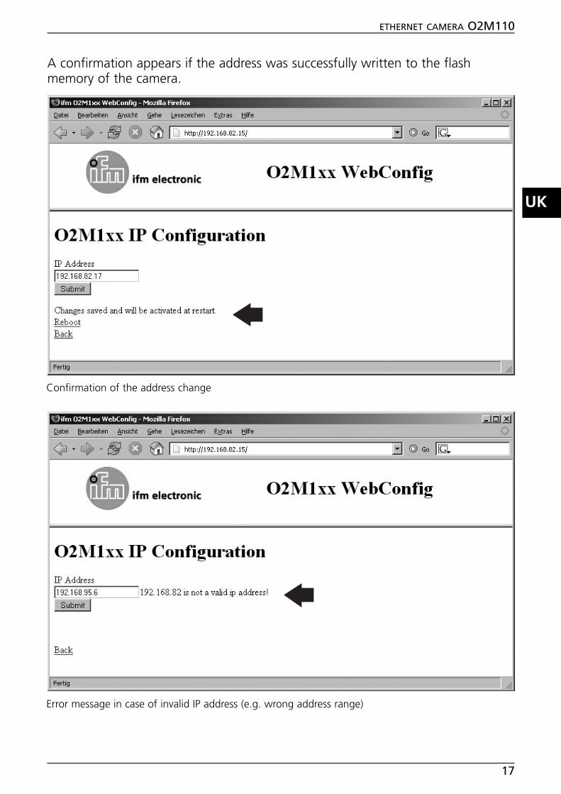
A confirmation appears if the address was successfully written to the flashmemory of the camera.
ETHERNET CAMERA O2M110
17
UK
Confirmation of the address change
Error message in case of invalid IP address (e.g. wrong address range)

An inadvertent, wrong address allocation makes subsequentcommunication with the camera impossible. For this reason, the followingfinal test must be carried out.
8. Click on “Reboot”.9. Enter the new IP address of the camera in the address line of the browser and
confirm with “Enter” (here e.g.: http://192.168.82.17/).If the address corresponds to the previously allocated address, the startwindow “O2M1xxx WebConfig” appears again.
10. Repeat the steps 2 to 9 with further cameras.
The new camera IP address will become effective on reboot.(camera supply voltage off/on).
ETHERNET CAMERA O2M110
18
O2M1xx IP configuration, reboot request to check the allocated IP address
�

6.2 Parameter setting PDM360
6.2.1 Library ifm_Camera_O2M_Vxxxxxx
The CoDeSys library “ifm_Camera_O2M_Vxxxxxx” is part of the CD-ROM“ecolog Software & Tools”. It contains all parameters and functions for thecontrol of the dialogue module PDM360 (art. no. CR1051) and the camera.
After installation of the CD, the library will be stored in the directory:...\ ifm electronic \ CoDeSys V2.3 \ Targets \ ifm \ Library \ ifm_CR1051
The library uses functions of the library “ifm_Camera_Vxxxxxx”. It is loadedautomatically.”ifm_Camera_Vxxxxxx” must not be inserted.
2 demo programs in the directory “...\ Projects \ DEMO_PDM” serve forintroduction (CR1051Demo_O2M_1CAM.pro undCR1051Demo_O2M_2CAM.pro).
6.2.2 Function CAM_O2M
The function is part of the above-mentioned library. It serves for parametersetting / control of one camera and its image data.One function block is required per camera.
ETHERNET CAMERA O2M110
19
UK
Function block CAM_O2M (extract CoDeSys programming surface)
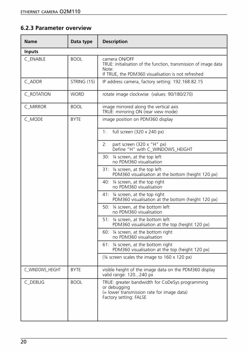
6.2.3 Parameter overview
ETHERNET CAMERA O2M110
20
Name Data type Description
Inputs
C_ENABLE BOOL camera ON/OFFTRUE: initialisation of the function, transmission of image dataNote:If TRUE, the PDM360 visualisation is not refreshed
C_ADDR STRING (15) IP address camera, factory setting: 192.168.82.15
C_ROTATION WORD rotate image clockwise (values: 90/180/270)
C_MIRROR BOOL image mirrored along the vertical axisTRUE: mirroring ON (rear view mode)
C_MODE BYTE image position on PDM360 display
1: full screen (320 x 240 px)
2: part screen (320 x “H” px)Define “H” with C_WINDOWS_HEIGHT
30: ¼ screen, at the top left no PDM360 visualisation
31: ¼ screen, at the top left PDM360 visualisation at the bottom (height 120 px)
40: ¼ screen, at the top right no PDM360 visualisation
41: ¼ screen, at the top right PDM360 visualisation at the bottom (height 120 px)
50: ¼ screen, at the bottom leftno PDM360 visualisation
51: ¼ screen, at the bottom leftPDM360 visualisation at the top (height 120 px)
60: ¼ screen, at the bottom rightno PDM360 visualisation
61: ¼ screen, at the bottom rightPDM360 visualisation at the top (height 120 px)
(¼ screen scales the image to 160 x 120 px)
C_WINDOWS_HEIGHT BYTE visible height of the image data on the PDM360 displayvalid range: 120...240 px
C_DEBUG BOOL TRUE: greater bandwidth for CoDeSys programmingor debugging(= lower transmission rate for image data)Factory setting: FALSE

ETHERNET CAMERA O2M110
21
UK
Name Data type Description
Outputs
C_RESULT BYTE 0: function not initialised or not active1: function successfully initialised
parameters successfully written2: function being processed3: error; connection disturbed or interrupted
parameter not writtenreinitialise function
97: check last byte of IP dresslast byte of the IP adress between cameraand PDM has to be different
98: PDM IP adress and camera IP adressare not in the same group
99: wrong IP adresscheck format of the input string
PDM_IP STRING (15) IP address of the connected PDM360

6.2.4 MODE combinations (1...4 cameras)
Full screen1 camera active, no visualisationC_MODE = 1C_WINDOW_HEIGHT = not defined
Part screen1 camera active, visualisation up to 120 px at the bottomC_MODE = 2C_WINDOW_HEIGHT = 120...240 px (height camera image)
¼ screen at the top left 1 camera active, visualisation 120 px at the bottomC_MODE = 31C_WINDOW_HEIGHT = not defined
¼ screen at the top right1 camera active, visualisation 120 px at the bottomC_MODE = 41C_WINDOW_HEIGHT = not defined
¼ screen at the bottom left1 camera active, visualisation 120 px at the topC_MODE = 51C_WINDOW_HEIGHT = not defined
¼ screen at the bottom right1 camera active, visualisation 120 px at the topC_MODE = 61C_WINDOW_HEIGHT = not defined
¼ screen at the top left / top right2 cameras active,visualisation 120 px at the bottom, controlled by camera 1Camera 1: C_MODE = 31Camera 2: C_MODE = 40C_WINDOW_HEIGHT = not defined (both cameras)
¼ screen at the bottom left / bottom right2 cameras active,visualisation 120 px at the top, controlled by camera 1Camera 1: C_MODE = 51, at the bottom leftCamera 2: C_MODE = 60, at the bottom rightC_WINDOW_HEIGHT = not defined (both cameras)
ETHERNET CAMERA O2M110
22
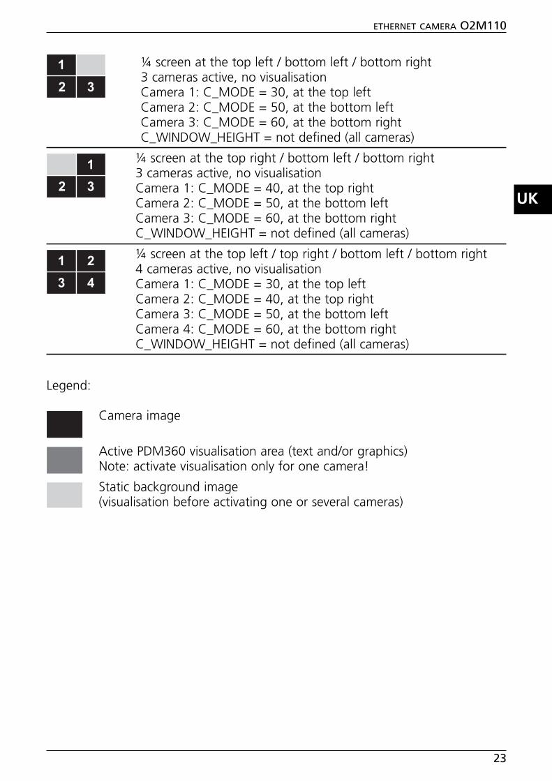
¼ screen at the top left / bottom left / bottom right3 cameras active, no visualisationCamera 1: C_MODE = 30, at the top leftCamera 2: C_MODE = 50, at the bottom leftCamera 3: C_MODE = 60, at the bottom rightC_WINDOW_HEIGHT = not defined (all cameras)
¼ screen at the top right / bottom left / bottom right3 cameras active, no visualisationCamera 1: C_MODE = 40, at the top rightCamera 2: C_MODE = 50, at the bottom leftCamera 3: C_MODE = 60, at the bottom rightC_WINDOW_HEIGHT = not defined (all cameras)
¼ screen at the top left / top right / bottom left / bottom right4 cameras active, no visualisationCamera 1: C_MODE = 30, at the top leftCamera 2: C_MODE = 40, at the top rightCamera 3: C_MODE = 50, at the bottom leftCamera 4: C_MODE = 60, at the bottom rightC_WINDOW_HEIGHT = not defined (all cameras)
Legend:
Camera image
Active PDM360 visualisation area (text and/or graphics)Note: activate visualisation only for one camera!
Static background image(visualisation before activating one or several cameras)
ETHERNET CAMERA O2M110
23
UK
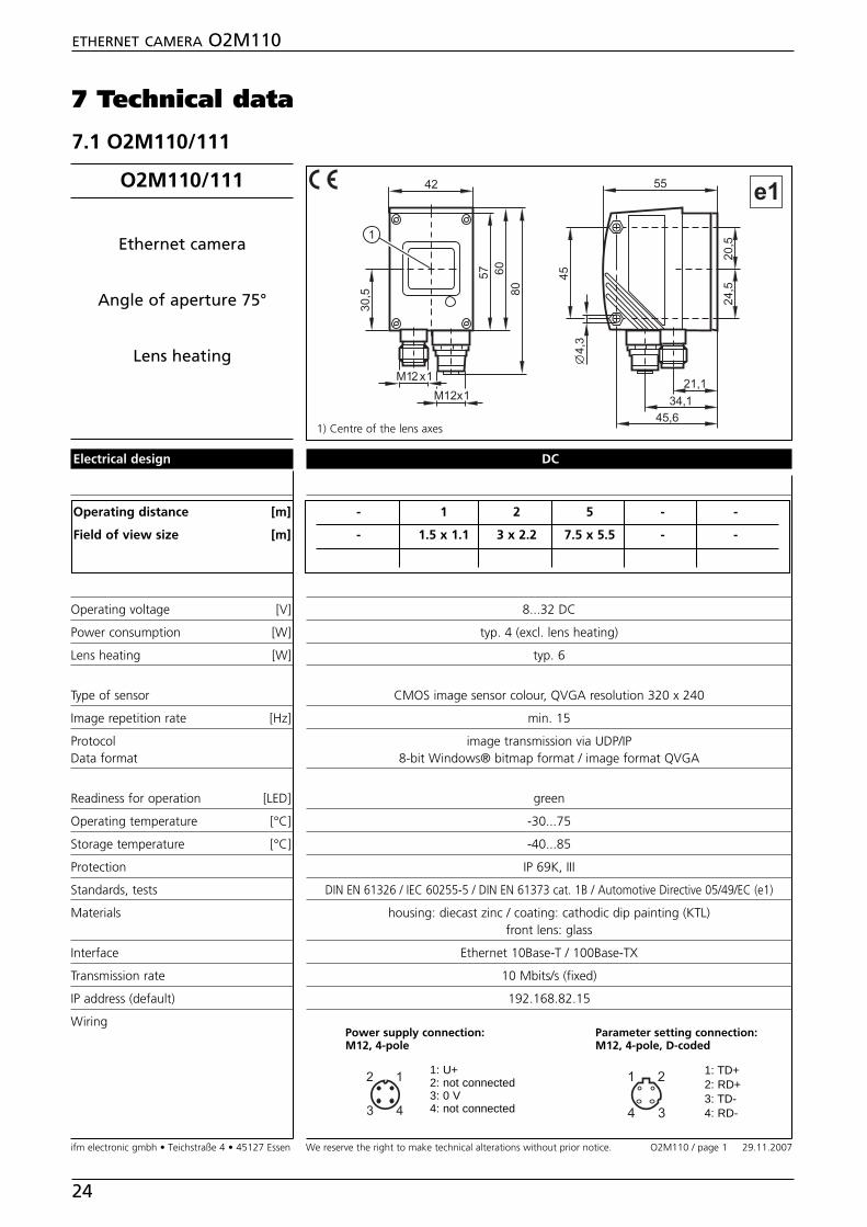
7 Technical data
7.1 O2M110/111
ETHERNET CAMERA O2M110
24
DC
- 1 2 5 - -
- 1.5 x 1.1 3 x 2.2 7.5 x 5.5 - -
8...32 DC
typ. 4 (excl. lens heating)
typ. 6
CMOS image sensor colour, QVGA resolution 320 x 240
min. 15
image transmission via UDP/IP8-bit Windows® bitmap format / image format QVGA
green
-30...75
-40...85
IP 69K, III
DIN EN 61326 / IEC 60255-5 / DIN EN 61373 cat. 1B / Automotive Directive 05/49/EC (e1)
housing: diecast zinc / coating: cathodic dip painting (KTL)front lens: glass
Ethernet 10Base-T / 100Base-TX
10 Mbits/s (fixed)
192.168.82.15
Electrical design
Operating distance [m]
Field of view size [m]
Operating voltage [V]
Power consumption [W]
Lens heating [W]
Type of sensor
Image repetition rate [Hz]
ProtocolData format
Readiness for operation [LED]
Operating temperature [°C]
Storage temperature [°C]
Protection
Standards, tests
Materials
Interface
Transmission rate
IP address (default)
Wiring
��
��
����
��������
���
��
��
6�
7����
7����
��
����
����
����
�
O2M110
Ethernet camera
Angle of aperture 75°
Lens heating
1: TD+2: RD+3: TD-4: RD-
Power supply connection:M12, 4-pole
Parameter setting connection: M12, 4-pole, D-coded
1: U+2: not connected3: 0 V4: not connected�
� �
�
� �
��
��
1) Centre of the lens axes
ifm electronic gmbh • Teichstraße 4 • 45127 Essen We reserve the right to make technical alterations without prior notice. 29.11.2007O2M110 / page 1
O2M110/111

8 Maintenance, repair, disposal
Keep the lens window of the camera free from soiling.Soiling may considerably affect the image quality!
To clean the lens window, do not use any detergents or solvents which mightdamage the front glass.
Do not open the housing, as the device does not contain any components whichmust be maintained by the user. The unit may only be repaired by themanufacturer.
Dispose of the device in accordance with the national environmental regulations.
9 Approvals/standards
Test standards and provisions → 7 Technical data.
The CE Declaration of Conformity and the e1 approval are available at:➔ Data sheet direct ➔ e.g. O2M110 ➔ Approvalswww.ifm-electronic.com
ETHERNET CAMERA O2M110
25
UK
�