DEVELOPMENT OFA COMPUTER AIDED SOFTWARE FOR POWER ...
10
.3'$. .1fe journal of Technology, Vol. 19(1), 25-33, 2010 Full Paper DEVELOPMENT OFA COMPUTER AIDED SOFTWARE FOR POWER TRANSMISSIONSHAFT DESIGN .WITH MULTIPLE 'CRITERIA ------------------------------------------~----------------------~--------~------------------~----, . D. A. Fadare Depcrtmenr afMechanical Enginctring FarulryofTechnology , University of Ibadan P.M.R 1, Ibadan, Nigeria Idci(/rcrla@)vcZhoo.coll1 O. YAkanbi De/JQrtmenrofMechanical Engineering Filculty of Technology , University of Ibadan P.M.B l,lbadan, Nigeria '." . J ABSTRACT Power transmission shafts, such as the crankshaft, impeller shaft, propeller shafts, camshafts ere, are essential machine elements with wide application in mechanical systems. The manual shaft design procedure is known to be tedious and complex because of large numbers of formulas, many. computations and' iteration procedures involved in the design. However, the use of Computer Aided Software (CAS) offers improved accuracy, high speed computations, reduced rigorousness and cumbersomeness involved in manual design procedure. This paper discusses the development of a Computer Aided Design and Draftsng (.cADD) of power transmission shafts with multiple design criteria (strength, torsional' rigidity, critical speed, Soderberg and lateral rigidity), Visual Basic 2008 was used for the implementation of the algorithm, while Fireworks was, used for the development of the Graphical User Interface (GUI). The developed CADDis called 'UI-CADSHAFT. The software was applied for a typical case study and validated with manual' design. Accurateresults with increased productivity about twenty folds over the manual design . are obtained. The software is fully interactive, user-friendly and runs stand- alone on Microsoft" Windows. Keywords: Shaft Design, Drafting, Compurer-Aided, Software development. 1. INTRODUCTION' Machines are combination of mechanical parts which transmit motion and/or forces in order to do work. The Power transmission shaft constitutes one of the most important machine elements in mechanical systems. Shafts, are most widely used machine elements in various mechanical engineering applications, especially in power . NOMENCLATURE d shaft diameter, mm r design shear stress, N/m2 Mb bending moment: Nm Mt torsional moment, Nm Kt combined shock and fatigue factor applied to torsion Kb combined shock and fatigue factor applied to bending R ratio of inside diameter to outside diameter K radius of gyration, mm I rectangular moment of inertia, mm4 di internal diameter, mm D outer diameter, mm L length of shaft between two bearings, mm N constant for the type of end supports Rg gear pitch radius, mrn. Rp pulley radius, mm Wg gear weight, N Wp pulley weight, N Wi weight of members on shaft pulley, gear, etc, N Tl tension in the tight side of the belt on pulley, N xn distance between mounted member and bearing, mm o gear pressure angle, deg' a columrt factor f3 pinion.cone angle for bevel gear (0) P power.lKw . ' , RPM rotational speed, rev/rnin E modulus of elasticity, N/m2 g acceleration due to gravity We critical speed.jad/sec. yi deflections, mm . G modulus of rigidity, N/m2 eO angle of twist Fv vertical forces Fh horizontal forces Fa axial load on the shaft, N a.. yield strength, N/m2 .. f factor of safety . endurance limit, 'N/m2 tension in the slack side-of belt, N inner shaft diarneter.rnrn outer shaft diameter, mm a~ T2 di do transmission. Generally, transmission shafts are used to transmit' power between the power producing unit and power absorbing unit. They are found in applications such as the crankshaft, impeller shaft, 'propeller shafts, camshafts etc. The application of a shaft usually determines its nomenclature. Shafts are usually cylindrical in shape lllS-9782 o 2010 Ife Journal of Technology . http://ijt.oauife.edu.ng UNIVERSITY OF IBADAN LIBRARY
Transcript of DEVELOPMENT OFA COMPUTER AIDED SOFTWARE FOR POWER ...

.3'$. .1fe journal of Technology, Vol. 19(1), 25-33, 2010
Full Paper
DEVELOPMENT OFA COMPUTER AIDED SOFTWARE FOR
POWER TRANSMISSIONSHAFT DESIGN .WITH MULTIPLE
'CRITERIA
------------------------------------------~----------------------~--------~------------------~----, .
D. A. FadareDepcrtmenr afMechanical EnginctringFarulryofTechnology ,University of IbadanP.M.R 1, Ibadan, NigeriaIdci(/rcrla@)vcZhoo.coll1
O. YAkanbiDe/JQrtmenrofMechanical EngineeringFilculty of Technology
, University of IbadanP.M.B l,lbadan, Nigeria
'." .J ABSTRACT
Power transmission shafts, such as the crankshaft, impellershaft, propeller shafts, camshafts ere, are essential machine elementswith wide application in mechanical systems. The manual shaftdesign procedure is known to be tedious and complex because oflarge numbers of formulas, many. computations and' iterationprocedures involved in the design. However, the use of ComputerAided Software (CAS) offers improved accuracy, high speedcomputations, reduced rigorousness and cumbersomeness involvedin manual design procedure. This paper discusses the developmentof a Computer Aided Design and Draftsng (.cADD) of powertransmission shafts with multiple design criteria (strength, torsional'rigidity, critical speed, Soderberg and lateral rigidity), Visual Basic2008 was used for the implementation of the algorithm, whileFireworks was, used for the development of the Graphical UserInterface (GUI). The developed CADDis called 'UI-CADSHAFT.The software was applied for a typical case study and validated withmanual' design. Accurateresults with increased productivity abouttwenty folds over the manual design . are obtained. Thesoftware is fully interactive, user-friendly and runs stand-alone on Microsoft" Windows.
Keywords: Shaft Design, Drafting, Compurer-Aided, Software development.
1. INTRODUCTION'
Machines are combination of mechanical parts which transmitmotion and/or forces in order to do work. The Power transmissionshaft constitutes one of the most important machine elements inmechanical systems. Shafts, are most widely used machine elementsin various mechanical engineering applications, especially in power
. NOMENCLATUREd shaft diameter, mmr design shear stress, N/m2Mb bending moment: NmMt torsional moment, NmKt combined shock and fatigue factor applied to torsionKb combined shock and fatigue factor applied to bendingR ratio of inside diameter to outside diameterK radius of gyration, mmI rectangular moment of inertia, mm4di internal diameter, mmD outer diameter, mmL length of shaft between two bearings, mmN constant for the type of end supportsRg gear pitch radius, mrn.Rp pulley radius, mmWg gear weight, NWp pulley weight, NWi weight of members on shaft pulley, gear, etc, NTl tension in the tight side of the belt on pulley, Nxn distance between mounted member and bearing, mmo gear pressure angle, deg'a columrt factor
f3 pinion.cone angle for bevel gear (0)P power.lKw . ' ,RPM rotational speed, rev/rninE modulus of elasticity, N/m2g acceleration due to gravityWe critical speed.jad/sec.
yi deflections, mm .G modulus of rigidity, N/m2eO angle of twist
Fv vertical forcesFh horizontal forcesFa axial load on the shaft, Na.. yield strength, N/m2..f factor of safety
. endurance limit, 'N/m2
tension in the slack side-of belt, Ninner shaft diarneter.rnrnouter shaft diameter, mm
a~T2dido
transmission. Generally, transmission shafts are used to transmit'power between the power producing unit and power absorbing unit.They are found in applications such as the crankshaft, impeller shaft,'propeller shafts, camshafts etc. The application of a shaft usuallydetermines its nomenclature. Shafts are usually cylindrical in shape
lllS-9782 o 2010 Ife Journal of Technology .http://ijt.oauife.edu.ng
UNIVERSITY
OF I
BADAN LIBRARY
26
and they provide supports for the other machine elements such asbearings, pulleys, wheel, sprocket and pinion. which mayvbemounted on shafts. They may be subjected to both torque andbending forces. rower is. delivered to the shaft by tangential forceand 'the. resultant torque (or twisting moment) setup within the.shaft, this power is then transferred to various machine elementslinked up to the shaft. Shafts can either be solid or hollow,uniform ..or variable cross sections, with keyways or splines. .
Transmission shafts, spindle, axle and machine shafts are the.dilferent types of commonly used shafts in mechanical systems. Theyare commonly made of steel arid its alloys. The material selection, forthe transmission shaft is mainly determined by the material heatueatability, wear resistance, machinability, notch sensitivity factor,and strength [1-5]. ,
, The design and production of transmission shafts are deeplyentrenched in mechanical design and engineering principles: itinvolves rigorous analysis to determine the stress, geometry 'anddimensions of the shaft. Designers are faced with the problems ofworking with large numbers of formulas, many computations. anditeration procedures involved in the design. These have made. theorthodox design procedures of shafts cumbersome, rigorous and.time consuming.
However, these problems can be overcome using the variousadvantages, utilities .and £lexibilities which modern high-speedmicro-computers offer for the design of shafts. Computer AIdedDesign (CAD) is defined by Ray [6] as any design activity.that'involves the effective use of computer to create, modlfy, analyse, oroptimize an engineering design. According to Serope [7], Computer.Aided Drafting commonly refers to the actual technical drawing ofcomponent using computer rather than a traditional drawing boardThe use of CAD is becoming increasingly popular in many fields ofengineering design. Different CAD-based software are nowcommercially available, while efforts are still being made by manyresearchers in the development of new and more sophisticatedsoftware for different applications in engineering design: such asmould design [8, 9], cam profile design (10; 11],leaflet blood-pumpvalves [12], while Ogedengbe and Aderoba [13] developed a CADsoftware using Visual Basic 6.0 for design of shafts based only onstrength criterion when the shaft has no axial loads. The aim of thispaper is to develop a Computer Aided Design (CAD) softwai:e forthe design and drafting of power transmission shafts based onmultiple design criteria. . ,
2. MATERIALS AND METIIODS
In developing this software, five deign criteria: (1) strength, (2)torsional rigidity, (3) critical speed or vibration, (4) Soderberg and
,(5) lateral rigidity were considered in order to determine theoptimum method for transmission shaft design. Relevant designequations based on different criteria were compiled from literatures.This was followed by the .implementation of the algorithm usingVisual Basic 2008 and Fireworks for the development of' a user-friendly application software. The developed CADD is called 'UI-CADSHAIT. The procedures for the design calculations arediscussed in the following sections.
, 2.1 Determination of torsional and bending moments
Bending and torsional moments are. the main factors'influencing shaft design. First step in shaft design for any givendesign criterion is to calculate the torsional moment onthe shaftfollowed by finding the maximum bending moment. the torsionalmoment, M,acting on the shaft isexpressed.as [14]: .
.' . All =9550*P' .'"'t RPM
D. A. Fadarc and OY Akanbi ,t!if:
If the load mounted on the shaft is gear, then vertical F, andhorizontalF, components of load on the shaft are given as (13):
(M ) .Fv = R: TanrpCosj3 +Wg
MtF/i=-.-Rg
(2)
Else, if the load mounted on the shaft is pulley, then v,FrticalF.and horizontal F" components of load on the shaft are given !ts [131
Fh= (7; -I: T2 )CosB
Fv = Wp-(7;+ Tl )5inB(3)
After the determination of F. and Fh• the' bending momentacting on the shaft is determined by drawing and analyzing thebending .moment diagram of the 'loaded shaft. The designcalculations based on the five criteria are discussed as follows:
2.2 Design of shaft Ior strength
The most common shaft loading condition is constant torqueand reversed bending. The diameter, d of a shaft subjected to torsionand bending loads having little or no axial loading is calculated from
, the ASME code [14] as:
[ , . lXd=Jrr(:~R4)[~(KbMS +(KtMtY ]
(1)
d.For solid shafts, R = -L =>0 because di -0. Else, for hollow
doshafts, the value of parameter R must be given.
For vertically, orientated shafts with axial loading, F. isinitially assumed to be' negligible, as a result, the term
aFad(1+R2) "
. as Fa iim • Hence, Equation (5) is reduced to Equation_ ,8
(4)and d is determined. For shafts with or without keyways.-initlalvalue of T is taken as 56 or 42 MN/m2, respectively. then the sadlusof gyration (K) is evaluated using' Equation (6) and a is thenevaluated for compressive loading condition using Equation (7) fordifferent ranges of:!:' ,while for tensile loads, a is taken to be equal
. . K
to 1and new value of Tis determined using Equation (5): If the-new.value of T is greater than initial T , it means the design is unsafe ..iteration process starts using higher value of diameter, d until newT is less than initial T ,at this stage the design is now safe. That is;the \·alueof diameter used to obtain lesser t is. the requireddiameter of shaft for the vertical orientation: [1]: ,
K =~ (6)4
lllS-9782 0 2010 IfeJournal of Technologyhtip:J/ijt.oauife.edu.ng
UNIVERSITY
OF I
BADAN LIBRARY

~!1.i' Developmcnt of A Com/Mer Aided Sofrwal'e For Po\Vcr Transmission Shaft DeMgn With MultipleCritcria
Lfor->115K
Where n • 1for hinged ends, n • 2.25 for fixed ends, n • 1.6forpartiallyrestrained ends. i. e. bearings .
2.3 Design of shaftIor Torsional rigidity
Design torsional rigidity isin accordance with the ASME code.The angle oftwist is determined using the expression [14]:
(d4 _ d4) = 584MtL (8)I GaD
,2.4 Design of shaft for critical speed or vibration
The equation used to determine the diameter of shaft based oncritical speed or vibration is expressed as [15]:
l N JXill = 30 gE,WnYn.c N (9)
rt IWny\n-:
Where the deflection, y" is expressed as
32Mb x, ( )Y = n L-xn End4 n
and the diameter is evaluated as:
2.5 Design of shaft for Soderderg
Soderderg • criterion is based on distortion energy andmaximum shear theories [16]. For distortion energy theory, thediameter, d of a shaft is ~xpressed as [13]:
d"[ ~~ [ (:: J'+~(:;nr (12)
27
For maximum shear stress theory, the diameter, d of a shaft isexpressed as [13]: ,
(7)
(13)
2,6 Design of shaft for Lateral rigidity. . " . ,
, The lateral deflection of the shaft is determined from bending i 'moment equation using the double integration method. The lateral rdeflection is expressed as [17]:
, = 32Mbmax * x [L-x]Ymax EJrd4,
(14)
, The procedural steps taken in designing the shaft based onlateral rigidity are:
• The highest of the values of diameter of the shaft isselected from the diameter obtained using theprevious design criteria (strength, torsional rigidity, 'critical speed and Soderberg) is selected as initialvalue and Equation (14) is used to calculatemaximum deflection, y max,'
• The procedure in Step 1is repeated using 5 mmincremental value of the diameter to determin'e thenew )'m,IX' this process is continued until new Yma.t isless than initialYmuxobtainedin step 1.
(10)I
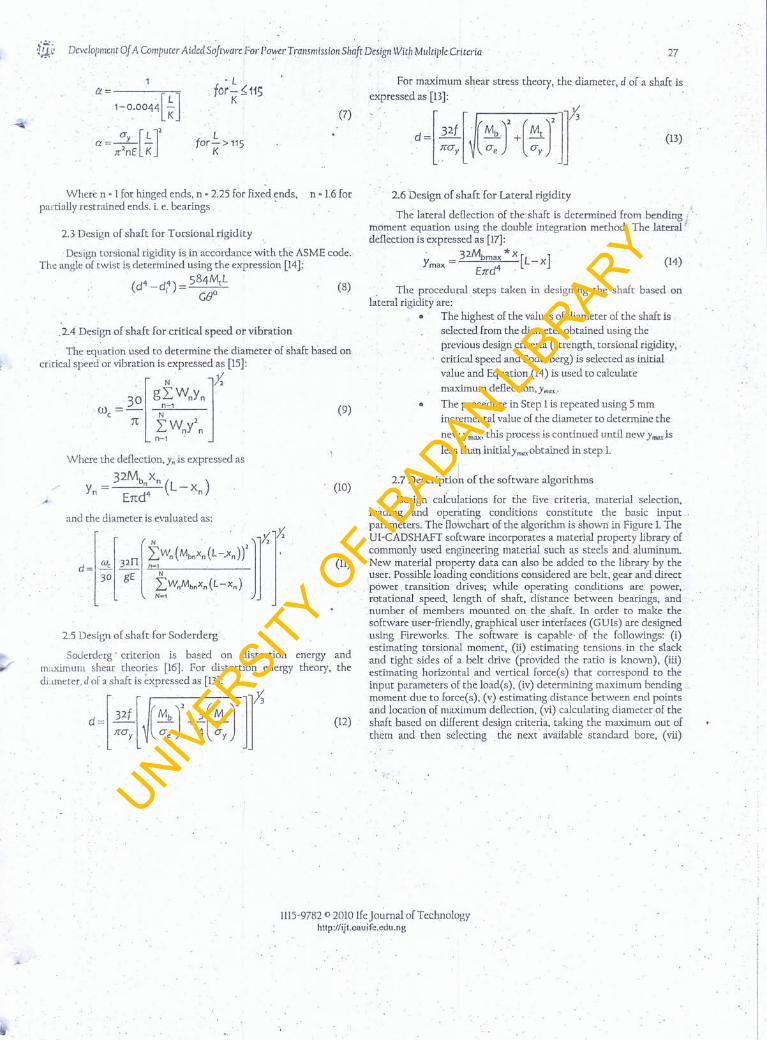
2,7 Description of the software algorithms, r
Design calculations for the five criteria, material 'selection,loading and operating conditions constitute the basic inputparameters. The flowchart of the algorithm is shown in Figure 1.TheUI-CADSHAFT software incorporates'a material property library ofcommonly used engineering material such as steels and aluminum.New material property data can also be added to the library by theUser, Possible loading conditions considered are belt, gear and directpower, transition drives; while operating conditions are power,rotational speed, length of shaft, distance between bearings, andnumber of members mounted on the shaft. in order to make thesoftware user-friendly, graphical user interfaces (GUIs) are designedusing Fireworks, The software is capable' of the followings: (i)estimating torsional moment, (ii) estimating tensions in the slackand tight sides of a belt drive (provided the ratio is known), (ill)estimating horizontal and vertical force( s) that correspond to theinput parameters of the load(s), (iv) determining maximum bending,moment due to foree(s), (v) estimating distance betweenend pointsand location of maximum deflection, (vi) calculating diarnerer of theshaft based on different design criteria, taking the maximum out ofthem and then selecting the next available standard bore, (vii)
. ;
(ll)
lIlS-9782 CllOlO Ifejournal of Technologyhttp.z/ijt.oauife.edu.ng
UNIVERSITY
OF I
BADAN LIBRARY
'itJ.~ Developmellt of A Computer Aided Sofrware For P0>vcr Trallsmission Shaft Design With Multiple Criteria 27
1(1= ,
1-0.0044[~ ]
, a [L]'a = Jr'~E K
Lfor-> 115
K
Where n • 1for hinged ends, n • 2.25 for fixed ends, n • 1.6 forpartially restrained ends. i. e. bearings .
2.3 Design of shaft-for Torsional rigidity
'Design torsional rigidity isin accordance with the ASME code.The angle oftwist is determined using the expression [14]:
(d4 _ d4) = 584MtL (8)I GgO
2.4 Design of shaft for critical speed or vibration
The equation used to determine the diameter of shaft based oncri tical speed or vibration is expressed as [15]:
l N ]X'wc,; 30 gN::'WnYn (9)
n 2::Wny\n-'
Where the deflection, y" is expressed as
32Mb Xn )- n L-xv; - End4 ( n
2.5 Design of shaft for Soderderg
Soderderg' criterion is based on distortion energy andmaximum shear theories [16]. For distortion energy theory, thediameter, d of a shaft is ~xpressed as [13]:
d~[!~[(::J+~(:JIf (12)
For maximum shear stress theory, the diameter, d of a shaft isexpressed as [13):
(7)
(13)
2.6 Design of shaft for La~cral rigidity. '. ~
The lateral deflection' of the shaft is determined from bending I'moment equation using the double integration method. The lateral rdeflection is expressed as [17]:
, = 32Mbmax *X [L _ xlYmax EJrd4 (14)
(10)
. The procedural steps taken in designing the shaft based onlateral rigidity are:
.' The highest of the values of diameter of the shaft isselected from the diameter obtained using theprevious design criteria (strength, torsional rigidity, 'critical speed and Soderberg) is selected as initialvalue and Equation (14) is used to calculate
maximum deflection, Y max.:
• The procedure in Step I is repeated using 5 mmincremental value of the diameter to determine the
new )'rn'tX,'this process is continued until newYmaxis
less than initial Yow, obtained in step 1.
iI '
2.7 Description of the software algorithms. I
Design calculations for the five criteria, material selection,loading and operating conditions constitute the basic inputparameters. The flowchart of the algorithm is shown in Figure 1. TheUI-CADSHAFT software incorporates a material property library ofcommonly used engineering material such as steels and aluminum.New material property data can also be added to the library by theUser. Possible loading conditions considered are belt. gear and directpower transition drives; while operating, conditions are power,rotational speed, length of shaft, distance between bearings, and.number of members mounted on the shaft. In order to make thesoftware user-friendly, graphical user interfaces (GUls) are designedusing Fireworks. The software is capable of the followings: (i)estimating torsional moment, (ii) estimating tensions in the slackarid tight sides of a belt drive (provided the ratio is known), (iii)estimating horizontal and vertical force( s) that correspond to theinput parameters of the load(s), (iv) determining maximumbending .'moment due to force(s), (v) estimating distance berweenend pointsarid location of maximum deflection, (vi) calculating diameter of theshaft based on different design criteria, taking the maximum out ofthem and then selecting the next' available standard bore, (vii)
(ll)
1115-9782 02010 lfe Journal of Technologyhttp://iJt.oauife.edu.ng
UNIVERSITY
OF I
BADAN LIBRARY
28 D. A. Fadarc and O.Y. Alwl10i
Display welcome screen
Enter password
Back or Exil ? Is pessword Ok?.?c..N",o_-'---tofYes
Yes
NoNo
smaterial ::Others?
Yes.Ye
Is steel = low- ::;Y;:.s'-- -lcarbon steel?
No
Is steel = medium >Y:.;8S=--_-<.,carbon?
Is steel :'malleable Yesand ductile cast iron? >-----<~
No
'Display code number.material conditions;Tensile slrength~"Yield strength, Endurance strength: modulus of elasUclly,
modulus of rlgidlty .
Fig. 1: Flow chart for the computer-aided shaft design (Ul-CADSHAFT)
1115-9?S2 0 2010 lfe Journal of Technologyhttp://ijl.O&uife.edu.ng
UNIVERSITY
OF I
BADAN LIBRARY

tN ..~:;.;: Development Of A Computer Aided Software For Power Transmtssion Shaft Design With Multiple Criteria
r-r- __ :..:.No,,< Is shaft withkeyway?
Select type of shaft= hollow=solid
Power supplied(kW),Speedrequired (I1PM), Length of
the shaft between bearings,number of members
mounted on the-shaft
Display torsional momentselect type of member,
= pulley=gear
Is member =pulley?
, Is memeber =gear?
Yes
29
No
,'. Enter pulleyweight,radius, drive angle,distance between
bearing 2 andpulley
, Enter gear weight ,gearradius, gear pitch pressure
angle, distance bewteenbearing 1and gear,angle for
'bevel gear
'Calculate maximum bending moment and distance betweenbearing 1and maximum deflection
Fig, I: Continued
1115-9782() 2010 lfejoumal of Technologyhttp://ijt.oauirc.edu.ng
UNIVERSITY
OF I
BADAN LIBRARY
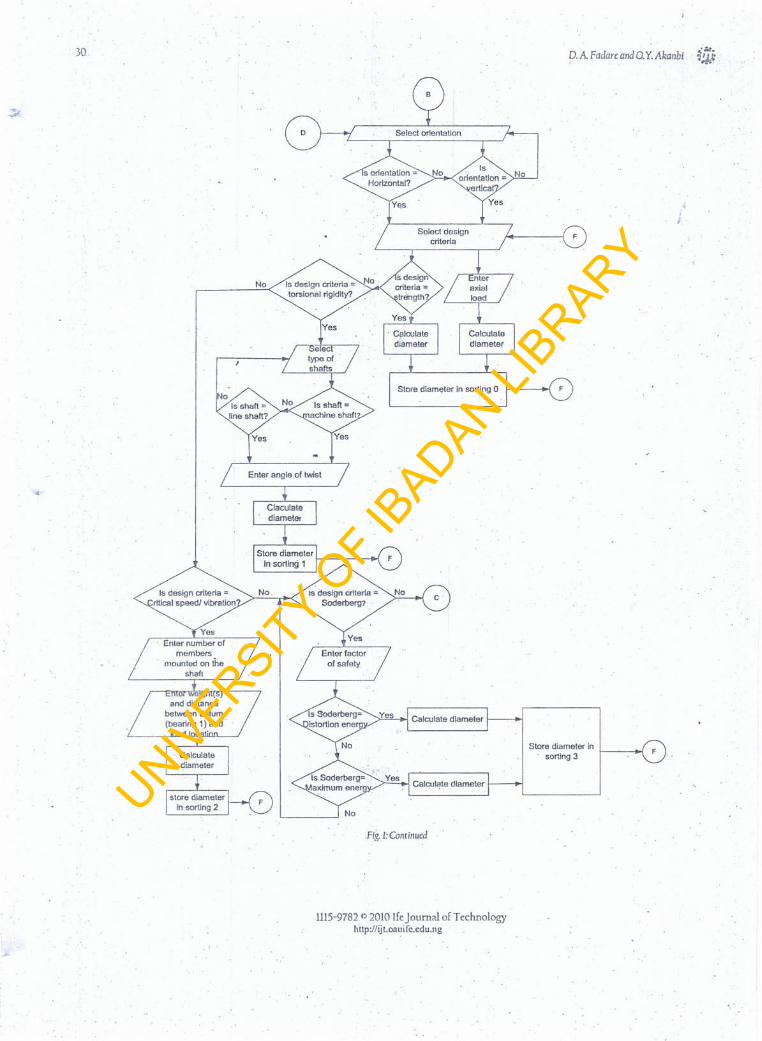
30. D. A Fadarc and O. Y. Akanbi
r-r Ncc·.:..0,- Is design criteria =torsional rigidity?
No. IS design criterla =Soderbery?
Is design criteria =ritieal speed! vibration
Calculate diameter
Stora diameter Insorting 3 F
Calculate diameter
,Fig. 1: Continued
lllS-9782 0 2010 Ife Journal of Technologyh·ttp:llijt.oauife.eQu.ng
UNIVERSITY
OF I
BADAN LIBRARY

·1ft: Development Of A COI11/JuterAidedSoftwa,'e For. Power Transl11ission Shaft Design With Multiple Criteria«,
Is designcriteria =Iateral >--..2N."o"-__ ----lo.-j
rigidity?o
Calculatemaximum.diameter
Display thenearest
standard shaftdiameter
Draft the shaft
E
Fig. 1:Colltinued
displayingthe result, (viii) drawing the expected shaft with label ofmounted members automatically.
2~8Validation of the software
The software was applied for a typical case study for design ofa power transmission shaft with design parameters shown in Table1, for a selected material made of AISI 1112 with mechanicalproperties -shown in Table 2. Results obtained from the softwarewere validated with manual calculations.
3. RESULTS AND DISCUSSION
31
"calculate" button. Then the desired criterion is selected from the"design criterion" pull-down menu and design diameter of the shaftis displayed in the output section. For this case study, the designdiameters of the shaft. based on five design criteria: strength,.torsional rigidity, critical speed or vibration; Soderberg and lateralrigidity are 57.1334 rnrn, 62.1006 mrn, 113355 mm, 0.1272mmand67.1006mrn, respectively. The highest calculated diameter of shafi: isdisplayed and the standard shaft diameter of 71.0 mm "isrecommended.
Tabid: Design input parameters used for the case study .,Parameter Description Nature/Value.
Shaft:Material AlS[ 1112steel
Solidwith keywayTypes:
Orientation:ConditionLoading Conditions:
Gear:WeightPitchradiusPressure angle
HorizontalHot-rolled.
900N375mm20"
Distance fromend pointAnglefor bevelgear
Pulley: .WeightRadiusDrive's angleDistance from end pointTension ratio .Operating Parameters:PowerRotational speedLength of shaftDistance between bearingsNumber of mounted membersAngleof twistFactor of safety
30mm0°
2700N625mm0"1300mm2.5
18.75kW150rpm,.1600mm1000mm2l deg/rn7
Figure 3 shows the summary window, which is divided intothree sections. The fist section shows. the design parameters usedinthe case study, the operating parameters are shown in the secondsection, while the design criteria used and calculated shaft diametersare shown in the third section. Figure 4 shows the drafting window,which displaces the front elevation. of the designed shaft, and alsoindicates locations of gear, pulley and-bearings on the shaft. -Thedrafting scale, calculated. shaft diameter and length of the shaft arealso shown on the draftingwindow,
The developed software was validated with .manualcomputation for the same case study using thedesign criteria forstrength and lateral rigidity.· The calculated shaft diameter .Iormanual computation is. found to be 57.13 mm and 59.49mmrespectively, while the application of the software produces. exactresult with higher decimal number. The software was also validatedwith existing software called SHAFTCAD [13] using design inputparameters in Table 2. The torsional moment, bending moment,calculated diameter and selected shaft diameter of 238.75 Nm, 386~67Nrn, 37.76 Nrn add 40 mrn respectively were obtained usig the UI-CAQSHAFT. The results· were exactly the same with that of·existing software. Increasedproductivity.of about twenty folds overthe manual design is obtained with the application of the software inthis case study. This because manual calculation lasts for twenty
Figure 2 shows the main window Ior the case study. The mainwindow is dividedinto two parts: input and output section. In theinput section, AISl1ll2 steel, hot-rolled, solid shaft with keyway forhorizontal orientation is selected from material library pull downIf\e~us. The mechanical properties of the selected ~aterial aredisplayed alterthe material selection. The operating parameters suchas: power to be transmitted, rotational speed, length of the shaft,distance between bearing, and number. and type of membersmounted on the shaft are entered, Torsional and maximum bendingruoments.and distance between end points and maximum deflectionure calculated and displaced in the output section on clicking the
1115-9782b 2010 lfeJournal of Technologyhttp://ijt.oauife.edu.ng
UNIVERSITY
OF I
BADAN LIBRARY

32 D. A. Fadarc and O.Y.Akanbi ~!/.i:three minutes and software computation takes about one and .hillminutes.
Table1: Dl!5ign iII/Jilt parameters usCdforthevalidatioll o!UI-CADSHAFf.Parame~er Description. Nature/Value
Material
Types:.Orientation:ConditionLoading Conditions:
Gear:WeightPitch radiusPressure angleDistance from end pointAngle for bevel gear'
Pulley:Weight
. RadiusDrive's angleDistance from end pointTension ratioOperating Parameters: .Power
Rotational speedLength of shaftDistance between bearingsNumber of mounted membersFactor of safety
AISII045 steel
Solid with keywayHorizontalHot-rolled
ONIOOmm20"250mm.0"
BOON.' 225 mm60"1250mm3
15kW
600rpm1250 mmiOOOmm26
4. CONCLUSION
The development and application of CAD software (UI-CADS HAFT) for design of power transmission shaft with multipledesign criteria has been presented. The result was found to beaccurate and the shaft was drafted and labeled neatly. with thedeveloped software. the' user is able to design and draft shaft at anextremely fast rate. The design was found. to increase productivity inthe design function by over ·twenty folds above manual -design.Hence the software can be used in the industries. as this will.improve the productivity of design engineers.
Table 1: Mtchanical Properties of the AIS11112 sreelTensile Yield .Enduranc Modulus ofstrength strength. e limit. elasticity.• Exl09(Ju (Jy a e (N/m')"
xlO' (N/m'j" xlO' xlO'(N/m'j" (N/m'j"
5.688 4.895
. Fig.4: Drafting windowSources: "sIJOtts (1988);-Roben (1000)
Modulus ofrigidity. G
xlO·(N/m')"
0.954 75
·J,&e~.,t.".. ~ .~ ~""y"""". ~"---'MIo."""'" ~£2Z31n,
DktaMe ••••.••••• 1-' ••. ~ ••• ~
r~"utlt! 0" SI,~n'J!h I! 10l:ll'h"~I1'--:---
rtt"l(l Uy StrL'1191h ~ 10'" ,N.-m:'j
Endurnnc.llmll.,U{l\tlm2j F'if.:"""~~
!-: .
~
- I~<-3!.=".;:.':'-.-~ .t..r ••f~
0-,_
~
""I3)4:oEIJ54~~\31f1
1\~X'leS:::_ ~12l:t'l4rm:(1~\31el
l . ..,..tls..... •...•.•.•.~_II............ c..IaoMIH~ jv.KIaJt~l ! o.. ....C5]••••• ,eI •• .-- •• -.. •••••• 1lIMI .,,---- ---- 111 : _ I'~ 1"'- 1 l.................. I"'"' --'----t, _ I:
.• Snr.:-tI~\oI';,., r- ~~-:t':J..:.:'{WJY3~r---
b •.• £-..,...."-~.,,...,twIt•••• .w •••• tlfIP ••
Fig1: Main window
c-
Fig.3: Summary window
, I1-"'lIIGe.eo~
ulcut.6a1lm-M,
S.I.a.d Shaft'. ot..,.. ••• , tm-t r:1 ,-----
h •••• .,SltMlf'IU ••1
REFERENCES
[I). R.S. Khurrni.und J.K. Gupta. Ma~hinc Design (EurasiaPublishing.House (PVT) Lrd, Ram Nagar. New DdlU-U0055, 2005).
[2]. W.J. Patton. Mechallical Power Transmission (Prentice-Hall lnc .•Englewood Cliff. New Jersey. USA,1980).
[3]. DD. Aa~n.J.W. Walter. and E.W. Charles. Machine Design-TheoryCllld Practice (Collier Macmillan International Edition. UK. 1975).
Ul5-9782 ('J 2010 lfe Journal of Technologyhttp://Ut.oauife;edu.ng
UNIVERSITY
OF I
BADAN LIBRARY

·i!Jj:DcvcIopmentOj A ComputerAided Soj~are.For Power Transmission Shaj; Design With Multiple Criteria.
[-'I], Y,M !illircs, Dc~igl1pfM«chi1lc Elcments (Macmillan Publishers,Toronto, Canada, 1965)
[5]. A.D. Deutschman,j.M. Walter, and E.W. Charles, Machine Design,Theory and Practice, (Macmillan Publishing Company inc., NewYork, USA, Pp. 331-375,1975) .
[6). M.S. Ray, The Technology and Applications of EngineeringMaterials (Prentice-Hall International Ltd, London, J 987).
[7]. K. Serope, ManufactUling Process for Erigineering Materia/s, 3r~edition(Wesley Publishing Company. Pp, 874, 1997).
[8J. C.K. Mok,K.S. Chin andJ.K. L-Ho, An Interactive Knowledge-!lased CAD System For Mould Design in Injection MouldingProcesses. The In'rcnillliorw/l(lunw/ (lrAJI'C/II(cc/ Manuracturing.TCc/lrIo/"gv, 17(1), 2001, 27· 38.
(9). Y. Takeuchi, M. Sakamoto, Y. Abe, R. Orira, and T. Sata,Development of a Personal CAD/CAM System for MoldManufacture Based on Solid Modeling Techniques. elRP Anrw/s ./'danu[uclllring Trcl!l1(llogy,36, 1989, 429~432.,
[10). Akinwole, O.A. Computer Aided Design of High Speed Cams:Software Development and Design Analysis of PolynomialFunctions (Project Report, Department of MechanicalEngineering, University of Ibadan, Nigeria, 2(04).
>
33
[II]. O.E. Simolowo, and O.A. Barniro, "Roller-Cam Systems Design:Development of a Profile Analysis Software", Pacific Journal.ofScience and Technology .. I O( 1),2009,20-34.
[12]. B.Knierbein, N. Rosarius, A. Unger, H. Reul and G. Rau ,CAD-design, Stress Analysis and in vitro Evaluation of Three Leaflet'Blood-pump Valves.jol!rIIa/l,(l3iotrla/i.wl Engincrril1g, 1.1,)992,275-286. .
J13)' T.!. Ogedengbe, and AA Aderoba, A Computerised Approach toDesign of Mechanical Power' Transmission Shafts. Nigerianjournalof Enginccring Researchand Development, 4, 2002, 35-46.
-. (14). AS. Hall, AR'Hcllowenko, G.H. Laughlin;P.C. Hills, and M.D. .Bennett, Theory and Problems afMac/linc Design, SI(metric) Edition, ISchaum's Outline Series, (McGraw-Hill Book Company,
. . Singapore. rr 331-37S~1982). . ... [15). M.F. Spotts, Design of MachineElemcnts, S'n edition (Prentice-Hall,. . New Delhi; India, 1988) .'
(16)' J.E. Shigley, ~ndC.R. Mischke, Standard Handbook of Machine Design,(McGraw-Hill Book Company, UK.Pp. 372-400, 1986).
[17). R.K. Rajput, Strength afMaterials in 51 units forEnginuring Students oiall.Diseip/ines, (S. Chand and Company Led, Ram Nagar: New Delhi.Pp. 649-653,2002).
c
1115-9782 (> 2010 lfe Journal of Technologytlttp:llijt.Q3uife.edu.ng
UNIVERSITY
OF I
BADAN LIBRARY