Development Of The Payload System And OBC Microcontroller ...
67
University of Texas at El Paso University of Texas at El Paso ScholarWorks@UTEP ScholarWorks@UTEP Open Access Theses & Dissertations 2020-01-01 Development Of The Payload System And OBC Microcontroller Development Of The Payload System And OBC Microcontroller Coding For A Cubic Satellite Performing An Additive Self-Repair Coding For A Cubic Satellite Performing An Additive Self-Repair Experiment In Space Experiment In Space Eduardo Macias-Zugasti University of Texas at El Paso Follow this and additional works at: https://scholarworks.utep.edu/open_etd Part of the Computer Engineering Commons, and the Electrical and Electronics Commons Recommended Citation Recommended Citation Macias-Zugasti, Eduardo, "Development Of The Payload System And OBC Microcontroller Coding For A Cubic Satellite Performing An Additive Self-Repair Experiment In Space" (2020). Open Access Theses & Dissertations. 2999. https://scholarworks.utep.edu/open_etd/2999 This is brought to you for free and open access by ScholarWorks@UTEP. It has been accepted for inclusion in Open Access Theses & Dissertations by an authorized administrator of ScholarWorks@UTEP. For more information, please contact [email protected].
Transcript of Development Of The Payload System And OBC Microcontroller ...

University of Texas at El Paso University of Texas at El Paso
ScholarWorks@UTEP ScholarWorks@UTEP
Open Access Theses & Dissertations
2020-01-01
Development Of The Payload System And OBC Microcontroller Development Of The Payload System And OBC Microcontroller
Coding For A Cubic Satellite Performing An Additive Self-Repair Coding For A Cubic Satellite Performing An Additive Self-Repair
Experiment In Space Experiment In Space
Eduardo Macias-Zugasti University of Texas at El Paso
Follow this and additional works at: https://scholarworks.utep.edu/open_etd
Part of the Computer Engineering Commons, and the Electrical and Electronics Commons
Recommended Citation Recommended Citation Macias-Zugasti, Eduardo, "Development Of The Payload System And OBC Microcontroller Coding For A Cubic Satellite Performing An Additive Self-Repair Experiment In Space" (2020). Open Access Theses & Dissertations. 2999. https://scholarworks.utep.edu/open_etd/2999
This is brought to you for free and open access by ScholarWorks@UTEP. It has been accepted for inclusion in Open Access Theses & Dissertations by an authorized administrator of ScholarWorks@UTEP. For more information, please contact [email protected].

DEVELOPMENT OF THE PAYLOAD SYSTEM AND OBC MICROCONTROLLER
CODING FOR A CUBIC SATELLITE PERFORMING AN ADDITIVE
SELF-REPAIR EXPERIMENT IN SPACE
EDUARDO MACIAS ZUGASTI
Master’s Program in Computer Engineering
APPROVED:
Rodrigo Romero, Ph.D., Chair
Joel Quintana, Ph.D., Co-Chair
Virgilio Gonzalez, Ph.D.
Stephen L. Crites Jr., Ph.D.
Dean of the Graduate School

Copyright ©
by
Eduardo Macias Zugasti
2020

Dedication
To my parents, Rosi Isela Zugasti Vargas and Eduardo Macias Sustaita.
You are the greatest motivation that I have in my life. Thank you for the support and love that
you give me every day. I could have not been done this without your advice. This is not only my
work; it is also yours. You raised me and taught me that I can do anything I wish, so I can say we
did it. Thank you and I love you.

DEVELOPMENT OF THE PAYLOAD SYSTEM AND OBC MICROCONTROLLER
CODING FOR A CUBIC SATELLITE PERFORMING AN ADDITIVE
SELF-REPAIR EXPERIMENT IN SPACE
by
EDUARDO MACIAS ZUGASTI, B.S.E.E.
THESIS
Presented to the Faculty of the Graduate School of
The University of Texas at El Paso
in Partial Fulfillment
of the Requirements
for the Degree of
MASTER OF SCIENCE
Department of Electrical and Computer Engineering
THE UNIVERSITY OF TEXAS AT EL PASO
May 2020

v
Acknowledgements
I would like to thank my committee members. Dr. Romero, thank you for your advice and
for recommending me to work in this project. You were the first professor that believed in me and
really tried to help me to succeed during my master’s program. Also thank you for the long time
spent advising, guiding, and talking to me. You are an example of a person to me. Dr. Joel
Quintana, thank you for accepting me in this project and letting me prove that I was able to do the
work. I have learned a lot working with you. Thank you for your patience, trust, and leadership.
You are an example of dedication to me. Dr. Virgilio Gonzalez, I would like to thank you for the
classes you have taught to me. Everything I learned with you resulted really useful for me when I
was building the ground station. You are an example of how to be a passionate professor for me.
Also, I would like to thank all of my OF2 teammates, Christian Lozoya, thank you for
always being with me coding and joking. It was a pleasure to work with you on this project.
Orlando Quezada, thank you for being always there when we were building the ground station and
for doing such a nice job making connectors. I would like to specially thank Perla Perez. Thank
you for being an example of dedication and always being there with me working. You are the best
mechanical engineer that I know.
Finally, I want to thank all cSETR members for always being nice and helping me in
everything I needed. You are the best.

vi
Abstract
Additive manufacturing, which is also known as three-dimensional printing, in space is
one of the most promising technologies advancing current capabilities for in-orbit space
manufacturing and assembly. Additive manufacturing contributes to the reduction of cost per
kilogram and number of launches, thus facilitating extraterrestrial colonization and deep-space
exploration. The state of the art includes advancing efforts inside the International Space Station
(ISS). However, the ISS is a controlled environment and, to the best of our knowledge, no
spacecraft or satellite has performed additive manufacturing tasks in the extreme environment of
outer space. In this work a 1U CubeSat named Orbital Factory II (OF2) was developed to perform
a technological capability demonstration featuring a 1-D printing mechanism that will deposit
conductive ink and simulate repairing of an electric circuit. OF2 was launched on a Northrop
Grumman Antares space rocket on November 2, 2019 and it was deployed from the CRS2 NG-12
(Cygnus) on January 31, 2020. This document presents the payload developed and the libraries
coded for the on-board computer (OBC) for this OF2 CubeSat. This is the first satellite ever
launched by the University of Texas at El Paso (UTEP).

vii
Table of Contents
Dedication ...................................................................................................................................... iii
Acknowledgements ..........................................................................................................................v
Abstract .......................................................................................................................................... vi
Table of Contents .......................................................................................................................... vii
List of Tables ................................................................................................................................. ix
List of Figures ..................................................................................................................................x
Chapter 1: Introduction ....................................................................................................................1
Chapter 2: Related Work .................................................................................................................5
Chapter 3: Fundamental Theory and Principles...............................................................................8
3.1 Embedded Systems ...........................................................................................................8
3.2 General Purpose Input and Output ....................................................................................8
3.3 Pulse Width Modulation ...................................................................................................9
3.4 Analog to Digital Conversion .........................................................................................10
3.5 Universal Asynchronous Receiver Transmitter ..............................................................11
3.6 Inter-Integrated Circuit ...................................................................................................11
3.7 Serial Peripheral Interface...............................................................................................13
3.8 Software Development in C ............................................................................................14
3.9 FreeRTOS .......................................................................................................................14
Chapter 4: System Design ..............................................................................................................15
4.1 Hardware .........................................................................................................................15
4.1.1 On-Board Computer (OBC) ................................................................................15
4.1.2 Accelerometers ...................................................................................................16
4.1.3 Magnetometers ....................................................................................................17
4.1.4 Diagnostic Module ..............................................................................................17
4.1.5 Power Management ............................................................................................18
4.1.6 File System..........................................................................................................18
4.2 Payload ............................................................................................................................19
4.2.1 Early Design........................................................................................................19

viii
4.2.2 Power Analysis ...................................................................................................21
4.2.3 Improvements in Design .....................................................................................22
4.2.4 Commercial Off-The-Shelf Cameras ..................................................................23
4.2.5 Assembly.............................................................................................................26
4.3 Software ..........................................................................................................................28
4.3.1 SCMPA Library ..................................................................................................28
4.3.2 Payload Library ...................................................................................................31
4.3.3 EPS Library .........................................................................................................35
4.3.4 UHF Library........................................................................................................36
4.3.5 SBAND Library ..................................................................................................38
4.3.6 Payload Software ................................................................................................38
Chapter 5: Testing ..........................................................................................................................42
Chapter 6: Analysis ........................................................................................................................46
6.1 Ground Station ................................................................................................................46
6.1 Communication ...............................................................................................................48
Chapter 7: Conclusions and Future Work ......................................................................................50
References ......................................................................................................................................53
Glossary .........................................................................................................................................54
Vita 56

ix
List of Tables
Table 4.1: SCMPA library instructions. ....................................................................................... 29 Table 4.2: Payload library functions. ............................................................................................ 32 Table 4.3: EPS library functions. .................................................................................................. 35 Table 4.4: UHF library functions. ................................................................................................. 37 Table 4.5: OF2 Instructions. ......................................................................................................... 43

x
List of Figures
Figure 1.1: Examples of different CubeSat units, courtesy of NASA ............................................ 2 Figure 1.2: Fist poster used to introduce OF2 in different presentations in 2018. ......................... 3 Figure 1.3: OF2 CubeSat fully assembled. ..................................................................................... 4 Figure 2.1: OF2 Payload CAD design, courtesy of Perla Perez. .................................................... 7 Figure 3.1: Example of a logic 1. .................................................................................................... 9 Figure 3.2: Example of a logic 0. .................................................................................................... 9 Figure 3.3: UART Connection. ..................................................................................................... 11 Figure 3.4: I2C Connection........................................................................................................... 12 Figure 3.5: SPI Connection. .......................................................................................................... 13 Figure 4.1: Layers for the OBC’s components, courtesy of EnduroSat. ...................................... 16 Figure 4.2: Payload module before being placed in the CubeSat. ............................................... 19 Figure 4.3: Early design of the nozzle using nylon wire. ............................................................. 20 Figure 4.4: Power analysis while the motor was running. ............................................................ 21 Figure 4.5: Design of the nozzle using the valve. ......................................................................... 23 Figure 4.6: Algorithm implemented to take pictures. ................................................................... 24 Figure 4.7: Experiment picture taken by the payload. .................................................................. 26 Figure 4.8: Poster used for presentation to NASA visitors in 2019 introducing a new payload
design. ........................................................................................................................................... 27 Figure 4.9: Assembled Payload. ................................................................................................... 27 Figure 4.10: Payload data flow and call graph. ............................................................................ 39 Figure 4.11: Design of payload’s communication protocol and registers. ................................... 41 Figure 5.1: Packet structure for UHF courtesy of EnduroSat. ...................................................... 43 Figure 5.2: Eduardo Macias Zugasti in Nanoracks’ clean room setting up OF2. ......................... 44 Figure 5.3: Poster used to present the OF2 project during ULA visit. ......................................... 45 Figure 6.2: Operation room at cSPACE ground station. .............................................................. 47 Figure 6.3: SBAND and UHF antennas. ....................................................................................... 48 Figure 7.1: Poster used for presenting the OF2 project during a visit from CalPoly members. ... 51 Figure 7.2: Members of OF2 team in clean room. ........................................................................ 52 Figure 7.3: Dr. Joel Quintana and Eduardo Macias Zugasti, two of the OF2 team members in
Nanoracks. .................................................................................................................................... 52

1
Chapter 1: Introduction
Satellites have become an important tool in modern life. They are used in a lot of different
applications. When someone is making a long-distance phone call, there are satellites working in
space to enable communication. Meteorologists use satellites to predict the weather and observe
environmental phenomena. The Global Positioning System (GPS) uses satellites to provide users
data to calculate their exact position. Television companies use satellites to broadcast their
programs. All of the data that cell phones use is processed using satellites to transmit and receive.
Moreover, satellites are used also for space exploration. On September 1977, the National
Aeronautics and Space Administration (NASA) launched a space probe named Voyager 1. Sixteen
days later, they launched their second space probe, named Voyager 2. On November 5, 2018,
Voyager 2 entered interstellar space. After 43 years, Voyager 2 has traveled more than 11 billion
miles from earth [1].
Even though this is the space device farthest from Earth, it is not the only one in space. At
present, there are more than 2000 satellites orbiting the Earth while performing various tasks.
Some of these satellites are a little bit bigger than a Rubik’s cube, 1U units measuring 10 cm x 10
cm x 10 cm, and they are called CubeSats. In 1999, Jordi Puig-Suari, a professor at California
Polytechnic State University (Cal Poly), and Bob Twiggs, a professor at Stanford University
developed the first CubeSat. Their intent was to provide affordable access to space for their
university science committee. Later on, many other universities around the world started to get
involved in space programs. CubeSat dimensions are based on the standard CubeSat “unit” which
is a 10cm cube with a mass approximately from 1 to 1.3 kg [2], as shown in Figure 1.1. The most
popular sizes are 1.5U, 2U, 3U, and 6U.

2
Figure 1.1: Examples of different CubeSat units, courtesy of NASA
Usually, CubeSats developed by universities are used for space research and experiments.
A significant problem found in space is that sometimes solar cells get broken or electronic
components get disconnected. This type of problems can be critical to some devices in space. A
solution for this problem could be to have an electronic self-repair system that could reconnect
electronic devices. In 2017, student members of the Center for Space Exploration and Technology
Research (cSETR) at UTEP won the United Launch Alliance (ULA) CubeSat Competition, also
called the CubeCorps competition. The prize from this competition was a spot for a CubeSat launch
mission to geostationary transfer orbit (GTO) in the future. With the goal of gaining experience,
cSETR decided to start CubeSat programs. The first satellite planned to be launched is Orbital
Factory II (OF2), which is a 1U CubeSat that will perform an experiment consisting in 3D printing
a conductive ink in space.

3
Figure 1.2: Fist poster used to introduce OF2 in different presentations in 2018.
The purpose of this is to propose a solution for those devices in space that get disconnected
or broken. Also, secondary missions that will be performed in this CubeSat include taking pictures
of the earth and testing an SBAND module designed by Lockheed Martin. After two years of work,
OF2 construction was completed. OF2 was launched on a Northrop Grumman Antares rocket on
November 2, 2019, and deployed from the CRS2 NG-12 (Cygnus) on January 31, 2020. This
document presents the payload developed and the software libraries developed for the on-board
computer (OBC) of this small satellite.

4
Figure 1.3: OF2 CubeSat fully assembled.

5
Chapter 2: Related Work
As Valvano said:
“The true engineering experience occurs not with your eyes and ears, but rather with your
fingers and elbows. In other words, engineering education does not happen by listening in class or
reading a book; rather it happens by designing under the watchful eyes of a patient mentor. So, go
build something today, then show it to someone you respect.” – J. Valvano [3].
This project was possible thanks to related work from people who spent time researching
and experimenting. For instance, the material selection for the ink was made based on Billah’s
research [4]. In 2017 Billah presented the results of his experimentation using two types of
electrically conductive ink. The first type was E1660 (Ecron) ink, which is made on a flake-based
silver particle. The second ink type was CB102 (Dupont), which is made of nano silver particles.
These two inks were chosen specifically because they passed NASA’s requirements for low
outgassing. Billah tested both inks under a thermal ambient analyzing the conductivity results from
these two types of ink under temperature ranging from -150 ºC to 350 ºC. Then Billah used a
thermal vacuum chamber to simulate outer space pressure and temperature and analyzed the
behavior of these two inks under these conditions. According to his results, both inks could work,
but the best option for this project was to use Ecron ink.
Also, at a certain point of the OF2 project, the need for using a slave microcontroller in
the payload became urgent. The OBC did not have enough general-purpose input-output (GPIO)
ports for peripherals to run the conductivity test, which is the primary mission of the CubeSat.
Actually, the OBC did not have any GPIO peripheral. It only had GPO pins, so it was not able to
do a conductivity test. After some research it was found that Felker used an MSP430FR4133
microcontroller [5]. In 2018 Felker presented a project about the development of the first CubeSat

6
from Rowan University. The mission of this satellite was to compare resistive memory against
non-resistive memory such as dynamic random-access memory (DRAM) and electrically erasable
programmable read only memory (EEPROM) under the effects of solar radiation including single
event upsets. The payload microcontroller chosen for this mission was an MSP430FR4133, which
is responsible for accumulating sensor and single event upset (SEU) data. The MSP430FR4133
will then search two types of memory, conductive-bridging random access memory and Flash, for
SEU-induced bit flips. Felker used and MSP430FR4133 because this microcontroller family
includes an architecture that is radiation-tolerant. After checking the specification sheet of this
microcontroller, a 64-pin version was available for the OF2 PCB. This microcontroller resulted
compatible to this project needs, not only because of its radiation tolerance, but because of the
number of pins that it has. This microcontroller also solved the GPIO problem in the OBC.
In addition, to checking how ink spreads over the experimental printed circuit board (PCB),
a small camera was considered for inclusion in the payload. However, it could not have been a
high-power consumption camera, it just needed to have enough resolution to analyze the results of
conductive ink deposition. Finally, when it was needed to decide which type of cameras were
going to be used in the project, Khurshid's survey resulted helpful [6]. In 2013, the CubeSat
Program of Pakistan’s Institute of Space Technology (IST) was going to launch their first CubeSat
ICUBE-1. The objective of this project was to familiarize IST students with a satellite imaging
system with image capture, analysis, compression, storage and retrieval. Khurshid, a member of
ICUBE-1 project, presented that year a survey comparing CMOS vs. charged-coupled device
(CCD) cameras. Based on his survey, CCD cameras consume more power and are likely to have
more errors than CMOS cameras. However, CMOS-camera data fetching is slower than CCD’s.
Based on Khurshid's survey of nine different cameras, the MicroCAM TTL camera was the best
7
fit for OF2 needs. MicroCAM TTL features include low power consumption, JPEG compression,
a UART serial interface, adjustable resolution, and a small size. The OF2 final decision was to use
this serial CMOS camera mainly because of its good resolution and low power consumption.
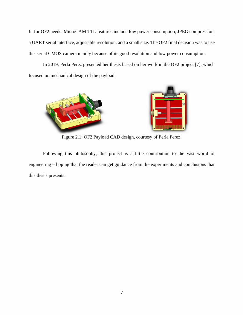
In 2019, Perla Perez presented her thesis based on her work in the OF2 project [7], which
focused on mechanical design of the payload.
Figure 2.1: OF2 Payload CAD design, courtesy of Perla Perez.
Following this philosophy, this project is a little contribution to the vast world of
engineering – hoping that the reader can get guidance from the experiments and conclusions that
this thesis presents.

8
Chapter 3: Fundamental Theory and Principles
The fundamental theory and principles for this project are based on microcontroller
applications. Microcontrollers are nowadays used for many different applications that include
some form of computation. They can be used to solve a variety of real-life problems. For instance,
microcontrollers are at the core of applications in the Internet of things (IoT) [8]. In this project,
the purpose of the use of microcontrollers is to solve a real-life problem that is crucial for space
exploration. As an illustration, when an ISS electronic device gets broken, an astronaut needs to
fix it or replace it. A good example of such devices are solar cells, sometimes they get damaged in
space and they cannot generate enough power to drive their electric system load. Thus, the idea of
implementing a microcontroller to run an experiment that potentially could fix a solar cell in space
could save a lot of time spent on repair. Moreover, this could open the doors for space exploring
satellites to survive more time in space.
3.1 Embedded Systems
A microcontroller is a control unit (CU) that can be reprogrammed. Because of this, and
using different data processing methods, a microcontroller can do different tasks without the need
for fixed-hardware digital design. This enables the user to spend more time on developing the
software and testing the system. When a microcontroller is programmed and implemented in a
system, this system is referred to as an embedded system. There are different data processing
techniques that can be applied in most microcontrollers. Basic techniques used in this project are
presented in the next sections of this chapter.
3.2 General Purpose Input and Output
In embedded systems, general purpose input and output (GPIO) is the simplest data
processing technique. It consists of reading a logical zero (0) for voltages between 0 volts (V), or

9
ground, and 0.7 volts. To read a logical one (1), the voltage range is between 2.5V and 3.3V. This
leaves a gap of 1.8 volts between logical 0 and logical 1.
Figure 3.1: Example of a logic 1.
Depending on the 0s and 1s that are read, the microcontroller can execute different tasks
from acting like a logic gate to more complex systems such as manipulating data sent from a
satellite in space to a specific ground station on earth.
Figure 3.2: Example of a logic 0.
3.3 Pulse Width Modulation
Pulse width modulation (PWM) is a technique to manipulate DC power transmission with
a microcontroller. Basically, PWM consists of an alternation of logical 0s and 1s in a certain
amount of time. For instance, let’s assume a microcontroller uses GPIO to transmit a signal every
millisecond. During this millisecond, for five hundred microseconds the GPIO signal is a 1, while
the other 500 microseconds the GPIO signal is a zero. If this signal keeps repeating this process

10
every millisecond the frequency of the signal results in 1KHz and the percentage of the modulation
is 50 percent because half of the period the signal is one, and the other half of the period the signal
is zero. If a DC voltmeter is connected to the signal, it will be observed that the output is half of
the voltage supplied by a 1. In this case, assuming that 1 is 3.3V the voltage read would be 1.65V.
In the same way, if the percentage is changed to ten percent, which is one hundred microseconds
as a 1 and nine hundred microseconds as a zero, the voltmeter would read 330 millivolts. This
technique is good for controlling the power of any output device that works using DC and is not
adversely affected by the PWM signal frequency.
3.4 Analog to Digital Conversion
Most of the sensors in the electronics field work in an analog way. This means producing
different continuous voltage levels that correlate with a physical measurement that is being read.
For instance, the TMP36 integrated circuit is a common temperature sensor. This sensor can
measure temperatures from negative 25ºC up to 125ºC. This sensor outputs a voltage that changes
10 millivolts for every 1ºC of temperature change. These changes in voltage could not be read
using GPIO because of the digital voltage levels that GPIO uses. The solution for this problem is
to use analog to digital conversion (ADC), where the microcontroller represents the voltage or
current in a specific continuous range with an integer number. The accuracy of the number read
depends on the resolution of the conversion and the voltage range. As an example, if a
microcontroller has a range from 0 volts to 3.3 volts and a precision of conversion of 214 bits, this
means that the integer number will be represented with the numbers from 0 to 16,383 (214-1) for 0
to 3.3 volts respectively. In this case 1.5 volts or 1,500 millivolts would be represented with the
integer number 7,446.

11
3.5 Universal Asynchronous Receiver Transmitter
Universal Asynchronous Receiver Transmitter (UART) is a serial communication mode
that does not need clock synchronization. Instead of a synchronization clock, devices have the
same baud rate, which is the number of bits that are transmitted per second. The most common
baud rate is 9600 bits per second. Nevertheless, some devices can go up to three million (3000000)
bits per second.
Figure 3.3: UART Connection.
When the communication is half-duplex, data can be sent bidirectionally but not
simultaneously. When there is no data transmission, the transmitter sends a 1 constantly, which
means the channel is idle. The standard protocol consists in the transmitter starting the transmission
by sending a start bit, which is a zero. After the start bit, a data package is sent which consists of
a byte (eight bits). To finish the transmission a stop bit is sent, which is a logical 1, thereafter the
receiver goes back to idle mode. Also, an extra bit can be sent between the last data bit and the
stop bit. This is called a parity bit and is used to ensure robust communication by detecting wrong
packages received with a single bit error.
3.6 Inter-Integrated Circuit
Inter-integrated circuit (I2C) is a serial bus for communication where a master can
communicate with different slaves. The bus consists of two lines, one for source clock

12
synchronization (SCL), and one for data transmission (SDA). When the clock line starts to
oscillate, the data line sends a one-byte packet. Every time that a byte has been sent in the data
line, the clock stops oscillating for a small amount of time and this separates every packet that is
being sent from other packets. Every slave has its own address, which is a seven-bit address where
the least significant bit is a signal for the slave to know if it will receive or transmit data. If this
last bit is a 0 from the master, this means transmit to the slave. On the other hand, if the last bit
received from the master is a 1, this means receive from the slave.
Figure 3.4: I2C Connection.
For instance, assuming that the address of a slave is 1011 110x in binary and the
master starts to transmit data to this slave and writes 1011 1100, this means that after an
acknowledge signal from the slave, the master is going to transmit one byte to the slave. On
the other hand, if the master writes 1011 1101, this means that the master is expecting to
receive a byte from the slave after the acknowledge signal.

13
3.7 Serial Peripheral Interface
Serial Peripheral Interface (SPI) is a synchronous communication approach that can
communicate a master with different slaves. The difference between I2C and SPI is that SPI does
not use addresses to communicate, but it uses a GPIO signal that enables the slaves that the master
needs to communicate with. There are two signals to send data, namely, Master Out Slave In
(MOSI) and Master In Slave Out (MISO). When the master wants to communicate with a slave it
sends a 0 using GPIO to select the slave. After this, the clock starts to oscillate and MOSI starts to
send data from master to slave. If the slave needs to send data to the master, MISO starts to send
data. A disadvantage when SPI is used is the number of connections that are needed. If there are
seven different slaves, seven different GPIO lines are needed for slave selection. A decoder would
be a good option to reduce the number of output pins from the master. However, it is needed to
connect every output of the decoder to the slave selection inputs.
Figure 3.5: SPI Connection.

14
3.8 Software Development in C
C is a programming language developed as a tool for programmers working in Bell Labs
in 1972 by Dennis Ritchie and Ken Thompson [9]. Nowadays C is one of the most common
programming languages used both by the hobbyist and the professional programmer. C language
results very useful for microcontrollers when programming at the register lever because it enables
the programmer to interact directly with memory and registers. Also, C language is directly related
to assembly language, which is the lowest abstraction layer between hardware and software. This
helps the programmer to understand what is going on inside of the microcontroller as the
instructions in C are being written. Microcontrollers used in this project have been programmed
employing C language using different integrated development environments (IDE), which resulted
helpful for debugging and behavior analysis.
3.9 FreeRTOS
FreeRTOS is a real-time operating system with a set of libraries for microcontrollers that
simplify the development of a real time embedded system. A disadvantage of programming using
this tool is that access to the microcontroller registers is partially limited. However, both the kernel
and the threads are easy to manipulate and the use of libraries for all the functions result in a more
convenient experience for the software engineer. The OBC was provided by EnduroSat and it
included a code base with a FreeRTOS library. Due to this situation, the software for the OBC was
written in C using FreeRTOS.

15
Chapter 4: System Design
To have a working embedded system, two things are necessary: hardware and software.
Hardware relates to the physical part of the system while software refers to the instructions
implementing algorithms to be executed inside the central processing unit (CPU). This chapter
begins with section 4.1 introducing the hardware provided by EnduroSat, the CubeSat hardware
vendor, because they provided the OBC and the software that controls it. The rest of the chapter
covers all of the software and hardware designed for the OF2 payload, which are the basis of this
thesis. In addition to meeting functional requirements, the design of payload subsystems aimed at
reducing the probability of failures. The main hardware and software subsystems that comprise
the OF2 payload are shown in Figure 4.10 as part of the system data flow and call graph.
4.1 Hardware
Some modules in this project were provided by Eurostat while some others were designed
in-house specifically for OF2. In the next sections, hardware modules are presented.
4.1.1 On-Board Computer (OBC)
Due to lack of time before the launch, an OBC was bought from EnduroSat, which is a
company specialized in CubeSat products. The OBC contains a detumbling controller, an attitude
determination controlling system, a diagnostic module, and power management. These control
units are manipulated using complex drivers. Peripheral devices provided in the embedded system
are two three-axis gyroscopes, two three-axis accelerometers, three magnetometers, five sun
sensors connected to solar panels, and an SD card. The microcontroller uses different data
transmission techniques to communicate with the drivers like GPIO, UART, I2C, and SPI. The
microcontroller provided is an STM32F42IIT6 and the IDE used to program this microcontroller
is System Workbench, containing a FreeRTOS C library. This made coding easier for the mission.
Even though some libraries were provided for basic communication, new libraries had to be built

16
since the payload was designed, tested and assembled using different commercial off-the-shelf
(COTS) products.
Figure 4.1: Layers for the OBC’s components, courtesy of EnduroSat.
4.1.2 Accelerometers
Two three-axis linear accelerometers are included in the OBC unit. These two
accelerometers are facing opposite sides of the printed circuit board (PCB). Accelerometers can
be used to measure the non-gravitational forces acting on the CubeSat. However, this could not be
implemented due to the lack of time with respect to the launch. Both accelerometers were tested
and they operate fine. Accelerometer communicate with the OBC via I2C.
17
4.1.3 Magnetometers
Two magnetometers are included in the OBC unit. In the same way as the accelerometers,
these two magnetometers are placed facing opposite sides of the PCB. The function of the
magnetometers is to read the magnetic field that is being exerted on the small satellite in space and
activate magnetorquers using PWM to make a detumbling system. This helps to avoid the Doppler
effect that would be generated if the satellite is spinning while it is orbiting around the earth. These
accelerometers communicate to the OBC via I2C and they are integrated in the system.
Nevertheless, a detumbling algorithm was not implemented due to lack of time before the launch.
4.1.4 Diagnostic Module
The diagnostic module collects data and manages data and an SD card connected to the
OBC via SPI. This diagnostic module keeps different text files for the most important modules,
namely, the modules for the Electric Power System (EPS), OBC, Payload, Solar Panels, and UHF.
Diagnostic values of the EPS have a one- or two-byte number for every register status that
can be decoded using Eurostat’s reference sheet. As an example, register one has a 12-bit ADC
conversion that refers to the battery voltage status. A number read from that register needs to be
multiplied times 0.0023394775 and the result is the actual voltage stored in the batteries from the
EPS in volts.
Diagnostic values of the OBC give an update of the actual time that is being read by the
real-time clock (RTC) and an update of status for the magnetometer sensors.
The diagnostic values of the solar panels give an update of the temperature of every solar
panel and the status of five photodiodes, each one connected to one axis of the CubeSat except for
the one that does not have a solar panel.
Diagnostics of the UHF module give a two-byte status register that can be decoded using
the user manual. This register can be used to determine if the antennas were deployed correctly,

18
the frequency of receiving and transmitting, the time period for beacon signals, and the number of
resets that the UHF module has performed.
Text files can be accessed and read sending a specific instruction ping (+2%) from the
ground station. This instruction is discussed in detail in table 4.5.
4.1.5 Power Management
All of the power management is controlled using an electric power system (EPS) designed
by EnduroSat. This system has two Li-Po battery packs encapsulated inside an aluminum box. The
capacity of these battery packs can go up to 20.98 Wh. The EPS has a system protection against
overvoltage, overcurrent, and overtemperature. Moreover, the system has a low power mode
algorithm that shuts down the battery bus when the raw voltage in the batteries goes below 3.05
volts. Once the batteries reach a voltage of 4.65 volts or above, the algorithm turns on the battery
bus again. Also, the EPS has two latch-up voltage switches that turn off the power supply for 5
volts and 3.3 volts. When the current exceeds 2 amperes, these latch up switches can be turned off
sending an instruction via I2C from the OBC. Also, the EPS system has 52 registers that can be
read to check the status of different modules. The system also has six connections for the solar
panels, so that it can get charged once the satellite is in space. Finally, the system has six general
purpose output (GPO) pins that can be accessed using the OBC. Some of these GPO pins have a
pre-assigned function, like turning on the OBC, UHF module, or SBAND module. Every GPO pin
has a diode connected to avoid reverse current flow, this is for safety purposes of the whole
CubeSat.
4.1.6 File System
The OBC has an SD card system to store data to be transmitted to earth. This storage uses
a FATS file system. The library implemented to send commands to the SD card using C is called
FATS FS. This is a multi-microcontroller file system that resulted useful.

19
4.2 Payload
Even though the payload can be considered hardware, it was decided to cover it in an
independent section. The purpose of this is to describe in more detail how the payload was
designed, tested, improved, retested, assembled, and included in the OF2 CubeSat. Every part of
the payload was designed and tested in UTEP by different team members of the OF2 project. In
the next sections a description of the printer is presented focusing in its electronics and sensors.
Figure 4.2: Payload module before being placed in the CubeSat.
4.2.1 Early Design
The primary mission for this CubeSat is to deposit a special ink that cures in space and
becomes conductive. At the beginning of the project, the ink was being released from a nozzle
using a nylon wire that was burned using electricity. The heat generated by the burned wire melted
wax on the tip of the nozzle. Using a motor driver and a stepper motor connected to a one-axis rail,
the ink could be spread over a PCB. The ink was tested in a vacuum chamber. After three minutes

20
the ink cured. Then it was taken out of the vacuum chamber and conductivity was tested using a
voltmeter to prove that indeed the cured ink was conductive.
Figure 4.3: Early design of the nozzle using nylon wire.
During this early experimentation, an Arduino processor was used. The OBC could not be
used for the experiments because it needed to control at least four GPIO peripherals. Due to the
lack of GPIO peripherals in the OBC, the Arduino processor became an early solution. However,
it was not a good idea to use an Arduino because it was not for sure at all that this device could
survive being exposed to space radiation. Another solution that was tested was to use a field
programmable gate array (FPGA). However, during the SETS Symposium in 2019, a presentation
about OF2 was given [10] and there was a recommendation to use a radiation-tolerant
microcontroller. Following these exchanges, the option of using an FPGA was discarded.
After looking for different options for the payload microcontroller and reviewing Felker
document [5] as mentioned in chapter 2, a Texas Instruments MSP430FR4133 microcontroller

21
was chosen as the OBC slave for payload control. This microcontroller was chosen specifically
because its architecture is proven to work under radiation. This microcontroller has an IC version
with 64 pins. This model fitted completely the specification needed for running the experiment.
For testing conductivity, twenty-six GPIO pins were used, ten pins would deliver signals, while
sixteen pins would read voltage in different areas of a PCB. If the ink cured properly, all of the
input pins in the PCB would be set resulting in a successful conductivity proof. The number of the
pins reading voltage and their result would be stored in the OBC’s SD card with a two-byte number
representing the number of pins that resulted positive after the conductivity test.
Time Measurement Batt. Voltage. Batt. Current Ext. Volts Ext. Current
Figure 4.4: Power analysis while the motor was running.
4.2.2 Power Analysis
After power analysis while the experiment was running, some modifications were needed
because the payload was consuming too much power. The current supplied to burn the wire was
between two and three amperes. Also, the stepper motor was consuming about 0.8 amperes for
ninety seconds when it was moving the nozzle around the rail. As can be seen in Figure 4.4, the
22
first column shows the timestamp, the second column shows the number of them measurement,
the third column shows voltage supplied in the battery bus in volts, the fourth column shows the
current consumed from the battery bus in milliamperes, the fifth column shows the external battery
voltage, and the last column shows the external battery current in milliamperes.
4.2.3 Improvements in Design
The results of this analysis showed that a shutdown of the CubeSat could happen while the
experiment was running. To avoid a possible shutdown, the whole payload was moved from the
regular voltage bus to the LUP bus and to avoid the two-ampere consumption generated by burning
the wire, an electric valve was implemented to open and close the nozzle. The specification sheet
of this valve recommends to use it at a temperature above 10 ºC degrees, otherwise the valve could
neither open nor close. Thus, a temperature sensor was connected to the valve. The first sensor
tested was a DS18B20, a digital sensor that uses a one-wire protocol. Since this protocol was not
included in the MSP430, this temperature sensor was exchanged for a TMP36, a temperature
sensor that works using ADC. A spring was placed inside the valve to release the ink and a pressure
sensor was tested to detect if the ink was being deployed. Nevertheless, this could not succeed
because the spring was not strong enough to create a considerable change in the pressure sensor.
Even with an amplifier, not too much change in the pressure sensor reading was detected. Thus,
the pressure sensor had to be discarded from the payload.

23
Figure 4.5: Design of the nozzle using the valve.
4.2.4 Commercial Off-The-Shelf Cameras
To see how the ink spread around the payload, a small camera was going to be connected
inside of the payload. For a secondary mission, another camera was going to be taking pictures of
the earth. Some inexpensive cameras were found at Spinel Electronics. The camera chosen for
earth pictures is a SC50MPA model. This is 5.0-megapixel camera. For internal pictures, not too
much resolution was needed. Thus, an SC03MPA model was chosen. This is a 0.3-megapixel
camera. Both cameras are built in the same fashion, the only difference is their resolution. They
are one fourth CMOS color image sensors with JPEG compression. They have a UART serial
interface at a baud rate of 115,200 bits per second. The communication protocol that these cameras
use is VC0706, which consists in sending and receiving data for instructions. Cameras turn on and
off using LUP buses and they were routed to the OBC bus using two pico-Molex connectors in the
payload. The algorithm implemented to take pictures from the OBC is shown in Figure 4.6.

24
Figure 4.6: Algorithm implemented to take pictures.

25
First, when the camera is turned on, an initial set of bytes is sent. After these bytes are sent,
an instruction is sent to set the resolution selected. The next step is to send an instruction to the
camera to get an image. If the camera answers back with and image taken, the next step is to ask
about data length of the image. Once the camera answers with the data length, this specific amount
of data is asked to be sent from the camera. At this point, the beginning of the picture will start
with 0xFFD8 because this is how the jpeg format starts. In the same way, the picture must finish
with 0xFFD9. If this ending is not received, the picture may be corrupted. Data is received and
stored in ASCII representing hex format, so once downloaded it needs to be converted from hex
to jpeg to see the actual picture. All of the answers from the camera are revised by the OBC. At
the end, the OBC creates an array with a report for any wrong answer from the camera during the
execution of the algorithm. If any step is wrong, the picture taken will not be stored in the SD card.
For internal pictures, two white LEDs were placed inside the payload board pointing to the
conductivity test PCB. LEDs turn on using the MSP430 slave. It was expected that in every pass
in space, the ground station would have between seven to nine minutes to download data from the
CubeSat. A picture would need about thirty minutes to be downloaded completely. Also, some
earth pictures may be completely black if the camera was pointing to space at the moment they
were taken. The solution to this data problem was to make every camera to take two pictures. One
with the lowest resolution possible and the second one with the full resolution. The lowest
resolution pictures need about 10 minutes for transmission and could be downloaded in 2 passes.
Cameras needed to be turned on only when they were taking pictures, so they are connected also
to the LUP voltages to save power. When everything was tested in a FlatSat. A PCB for connecting
everything in the payload was designed and tested. The MSP430FR4133 was debugged and coded
using a spy-bi-wire connection. Instead of buying an MSP430 debugger, an MSP430FR4133
Launchpad was bought and connected to the spy-by-wire pins of the IC in the PCB. After a few
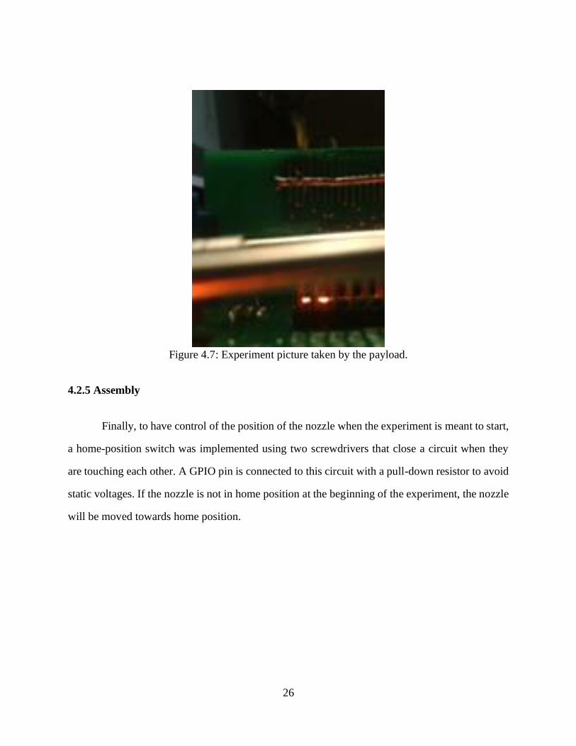
corrected versions of the PCB, the first picture taken by the payload and controlled by the OBC
was taken, thus running a successful experiment.
26
Figure 4.7: Experiment picture taken by the payload.
4.2.5 Assembly
Finally, to have control of the position of the nozzle when the experiment is meant to start,
a home-position switch was implemented using two screwdrivers that close a circuit when they
are touching each other. A GPIO pin is connected to this circuit with a pull-down resistor to avoid
static voltages. If the nozzle is not in home position at the beginning of the experiment, the nozzle
will be moved towards home position.

27
Figure 4.8: Poster used for presentation to NASA visitors in 2019 introducing a new
payload design.
When the experiment was run, sometimes the ink started to leak outside of the objective
PCB board. If this could happen in space, there is a possibility for the ink to spread around critical
components of the CubeSat creating a short circuit. To avoid this possibility the payload was
wrapped in Kapton tape.
Figure 4.9: Assembled Payload.

28
4.3 Software
All the software for this project was written in C. The OBC has an
STM32F42IIT6 microcontroller, which is based on the ARM Cortex M4 processor. The main
clock frequency of this microcontroller can go up to 180 MHz and consumes typically 104 mA. It
has 2MB for program memory and 256kB of RAM. EnduroSat provided basic code using
FreeRTOS and libraries for the devices included in the OBC. The software development kit (SDK)
used is System Workbench, which is an Eclipse-based platform. Even though basic libraries were
provided by the OBC vendor, others had to be written to meet the needs of this mission. For the
payload an MSP430FR4133 was used. This is a Texas Instruments mixed signal microcontroller
with a 16-bit RISC architecture that can operate at 16 MHz. However, it was used at a frequency
of 1MHz for this project. This microcontroller consumes 139 microamperes because it was
programmed to be in low power mode when not in use. It has 15KB of program flash memory and
2KB of RAM. The software development kit used for programming this microcontroller is Code
Composer Studio provided by TI and it is also an Eclipse-based platform. The microcontroller was
programmed at the register level using only the msp430.h header file.
4.3.1 SCMPA Library
The OBC has three UART channels available. One is used to communicate with the UHF
antenna module, another one is used for ground-station communications, and the last one is
intended to be used for payload. At the beginning, it was planned to use one camera to
communicate using UART and the other one with SPI. However, after a few weeks this task
resulted harder than expected. Then the option of using both cameras with UART was put on the
table. The problem with this alternative was that the OBC only had one UART bus and both
cameras used the same communication protocol. The baud rate could be changed in one of the
cameras but this could cause a problem if the cameras get reset, because by default both have a
baud rate of 115,200 bits per second. A decoder was another option, but in the end the

29
communication UART bus was tested and worked without any interruption in other tasks of the
OBC. Every picture that is taken successfully is stored in the SD card in a text file with a unique
identification number in the name of the file. In Table 4.1, the functions developed are presented
with a brief description.
Table 4.1: SCMPA library instructions.
Function void take_picture(char cam);
Brief Depending on the character received, the OBC will take an internal picture or an external
picture.
Param in char cam
Return void
Function void SC03MPA_TAKE_PICTURE(char s);
Brief Depending on the character received, the internal camera will take a low-resolution picture
or a high-resolution picture.
Param in char s
Return void
Function void SC50MPA_TAKE_PICTURE(char s);
Brief Depending on the character received, the external camera will take a low-resolution picture
or a high-resolution picture.
Param in char s
Return void
Function void SC50MPA_ON (void);
Brief Send a specific set of bytes that turn on external camera.
Param in void
Return void
Function int SC50MPA_GET_IMAGE (void);
Brief Send the instruction to external camera to get an image.
Param in void
Return Answer from the camera following VC0706 communication protocol.

30
Function int SC50MPA_READ_IMAGE_DATA_LENGTH (void);
Brief Send the instruction to external camera to get the number of bytes of the image taken.
Param in void
Return Answer from the camera following VC0706 communication protocol.
Function int SC50MPA_READ_IMAGE_DATA (char s);
Brief Send the instruction to send the bytes of the picture and then save them in the SD card in a txt file.
Param in void
Return Answer from the camera following VC0706 communication protocol.
Function int SC50MPA_RESOLUTION_SELECT (int Res);
Brief Select the resolution for the picture to be taken
Param in void
Return Answer from the camera following VC0706 communication protocol.
Function int SC50MPA_STOP (void);
Brief Stop taking pictures from external camera
Param in void
Return Answer from the camera following VC0706 communication protocol.
Function int SC03MPA_RESET (void);
Brief Send a specific set of bytes that turn on internal camera.
Param in void
Return void
Instruction int SC03MPA_GET_IMAGE (void);
Brief Send the instruction to internal camera to get an image.
Param in void
Return Answer from the camera following VC0706 communication protocol.
Function int SC03MPA_READ_IMAGE_DATA_LENGTH (void);
Brief Send the instruction to internal camera to get the number of bytes of the image taken.
Param in void
Return Answer from the camera following VC0706 communication protocol.

31
Function int SC03MPA_READ_IMAGE_DATA (char s);
Brief Send the instruction to send the bytes of the picture and then save them in the SD card in a txt file.
Param in void
Return Answer from the camera following VC0706 communication protocol.
Function int SC03MPA_BAUD_RATE_SELECT (int Baud03);
Brief Change the baud rate of the internal camera.
Param in void
Return Answer from the camera following VC0706 communication protocol.
Function int SC03MPA_COMPRESS (int comp);
Brief Change the compression ratio of the internal camera.
Param in void
Return Answer from the camera following VC0706 communication protocol.
Function int SC03MPA_RESOLUTION_SELECT (int Res);
Brief Change the resolution of the internal camera.
Param in void
Return Answer from the camera following VC0706 communication protocol.
Function int SC03MPA_STOP (void);
Brief Stop taking pictures from internal camera.
Param in void
Return Answer from the camera following VC0706 communication protocol.
4.3.2 Payload Library
The payload is controlled by a TI MSP430F4133 microcontroller. However, this
microcontroller only acts as a slave receiving instructions from the OBC master. Both
microcontrollers interact using I2C. A custom application protocol was designed for
communication of these two devices. This protocol is explained in detail in chapter 4 section 4.3.6.
The OBC has three I2C buses, the one selected to communicate with the MSP430 is the payload

32
bus. The address of the MSP430 is 0xD0. The MSP430 is in low power mode and as soon as it
gets an instruction from the OBC, it executes the instruction and goes back to low power mode.
When the experiment was being tested, sometimes the EPS was shutting down the whole CubeSat
because the batteries did not have enough power. To avoid this problem, a threshold voltage of 3.9
volts was set at the beginning of the experiment. If there were a need to force the experiment
avoiding the threshold voltage, a “force” variable is set to run the experiment. Once the experiment
is done, the conductivity test results are stored in a file called “test.txt.” All of the functions needed
to run the experiment by the OBC are in a file called “payload.c” and “payload.h”. Also, some
functions were created to have an updated status of the most important modules which are EPS,
UHF, OBC, Payload, and Panels. All of these files contain a timestamp based on the real-time
clock inside the OBC. These functions are discussed in Table 4.2.
Table 4.2: Payload library functions.
Function uint8_t check_home(void);
Brief Check if the nozzle is in home position.
Param in void
Return uint8_t 1 (true) or 0 (false) for home position.
Function void move_nozzle(char position, int steps);
Brief Move the nozzle towards (‘+’) home position or against (‘-’) home position the desired
number of steps for the stepper motor.
Param in char position, int steps
Return void
Function void deploy_ink(int force);
Brief Open valve to deploy ink.
Param in int force
Return void
Function int check_temperature (void);
33
Brief Check if temperature is above 10°C to open the valve. This function returns the temperature
in an integer representing °C.
Param in void
Return int
Function void LEDS_ON (void);
Brief Turn on white LEDs from payload to take a picture of the experiment with the internal camera.
Param in void
Return 1 (true) or 0 (false) for home position.
Function void LEDS_OFF (void);
Brief Turn off LEDs from payload.
Param in void
Return 1 (true) or 0 (false) for home position.
Function void enable_mux_read_demux (uint8_t test);
Brief Run conductivity test and check conductivity in specific pin.
Param in uint8_t test
Return void
Function void log_test(uint8_t I,uint8_t da);
Brief Create log file to store the experiment result of specific pin.
Param in uint8_t I, uint8_t da
Return void
Function void stop_ink(void);
Brief Close the valve to not deploy ink anymore.
Param in void
Return void
Function void I2C1_Reset(void);
Brief Reset payload I2C to default settings.
Param in uint8_t test
Return void

34
Function void logger (char data[], char path[]);
Brief General function that creates a file in a specific folder with the data requested.
Param in char data, char path
Return void
Function void loggerEPS (void);
Brief Create a file called “EPS.txt” storing all of the status register numbered from 0 to 52. This file can be also opened in excel.
Param in void
Return void
Function void loggerUHF(void);
Brief Create a file called “UHF.txt” which present the actual status of the UHF. This file can also
be opened in excel
Param in void
Return void
Function void loggerOBC(void);
Brief Create a file called “OBC.txt” which present the last reads of the magnetometers and the
accelerometers in the OBC. This file can also be open in excel.
Param in void
Return void
Function void loggerPayload(void);
Brief Create a file called “PAY.txt” which present the status of the Payload.
Param in void
Return void
Function void loggerPanels(void);
Brief Create a file called “PAN.txt” which present the last reads of the from the photovoltaic
sensors and the temperature sensors in every solar panel. This file can also be open in excel.
Param in void
Return void

35
4.3.3 EPS Library
The EPS has its own microcontroller and some instructions can be sent to it to manipulate
the GPIO of the OBC and check the voltage and current of different buses and batteries in the EPS
module. The interface is via I2C and the address of the EPS module is 0x18, but it is a 7-bit address,
so this address needs to be shifted one bit to the left in the OBC code. Some functions had to be
developed for power analysis and debugging. Functions are in the files named “EPS.h” and
“EPS.c”. The functions written in this file are presented in Table 4.3.
Table 4.3: EPS library functions.
Function void Read_EPS_Reg (uint8_t regNumber);
Brief Reads a specific register of the EPS module and stores it in a global array.
Param in uint8_t regNumber
Return void
Function float EPS_Battery_Voltage (void);
Brief For debugging purposes. Reads register 1 which stores the voltage of the battery bus in
ADC format. Then multiplies it by a constant and prints it out in the terminal. This function
returns a float variable for the voltage in volts units with 2 decimals precision.
Param in void
Return float
Function float EPS_Battery_Current (void);
Brief For debugging purposes. Reads register 2 which stores the voltage of the battery bus in ADC format. Then multiplies it by a constant and prints it out in the terminal. This function
returns a float variable for the current in milliampere units.
Param in void
Return float
Function float EPS_Extern_Battery_Voltage (void);
Brief For debugging purposes. Reads register 3 which stores the voltage of the raw battery in
ADC format. Then multiplies it by a constant and prints it out in the terminal. This function
returns a float variable for the voltage in volts units with 2 decimals precision.
Param in void
Return float

36
Function float EPS_Extern_Battery_Current (void);
Brief For debugging purposes. Reads register 4 which stores the current of the raw battery in ADC format. Then multiplies it by a constant and prints it out in the terminal. This function
returns a float variable for the current in milliampere units.
Param in void
Return float
Function void Power_Analysis (void);
Brief For debugging purposes. Creates a file called “POW.txt”. This file has 6 columns
containing a timestamp, number of row, battery bus voltage read, battery bus current read,
raw battery voltage read and raw battery current read.
Param in void
Return void
Function void Enable_LUP (uint8_t v);
Brief Enables LUP bus voltage for 5 volts (int 5) or 3.3 volts (int 3).
Param in uint8_t v
Return void
Function void Disable_LUP (uint8_t v);
Brief Disables LUP bus voltage for 5 volts (int 5) or 3.3 volts (int 3).
Param in uint8_t v
Return void
4.3.4 UHF Library
This CubeSat has two antennas for communication: a UHF antenna and an experimental
SBAND antenna provided by Lockheed Martin Space. The primary antenna is a UHF antenna
provided by EnduroSat. This antenna is set to communicate at a frequency of 435.04 MHz. By
default, it uses a two-frequency shift key (2GFSK) modulation with a data rate of 9600 bits per
second, and a frequency deviation of 2.4 KHz. The parameters and other options in the antenna
can be configured using the UART. By default, the antenna is neither in beacon mode or pipe
mode. Also, an instruction is necessary to be sent to the UHF module to deploy the antennas once

37
it is in space. A library was written to interact with the UHF antenna module. The files are named
“UHF.h” and “UHF.c.” The functions inside this library are presented in Table 4.4.
Table 4.4: UHF library functions.
Function void UHF_On (void);
Brief Turn on the GPO from the OBC to turn on the UHF.
Param in void
Return void
Function void UHF_Pipe_Mode (void);
Brief Make the UFH to work in pipe mode, so that data can be transmitted and received.
Param in void
Return void
Function void UHF_Transmit(char *msg);
Brief Once the UHF is in pipe mode, this function transmits the data contained in the variable
“msg” in ASCII format.
Param in char *msg
Return void
Function void UHF_Receive (uint32_t t);
Brief Once the UHF is in pipe mode, this function runs a timer and keeps the OBC waiting for
that amount of time to receive data using a DMA interrupt.
Param in uint32_t t
Return void
Function void UHF_Beacon_Mode(void);
Brief Changes the UHF from pipe mode to beacon mode.
Param in void
Return void
Function void UHF_Automatic_Deploy_Enable(void);
Brief Give the instruction to the UHF to deploy the antennas.
Param in void

38
Return void
Function void UHF_Check_Antenna(void);
Brief Check if the antennas have been deployed. The answer is stored in a global variable called
UHF_Ans.
Param in void
Return void
Function void UHF_Stop_Transmission(void);
Brief Disable UHF pipe mode.
Param in void
Return void
Function char Check_Pipe_Mode (void);
Brief Check if UHF is in pipe mode.
Param in void
Return char
4.3.5 SBAND Library
A secondary mission of this CubeSat is to test a patch antenna designed by Lockheed
Martin Space. The antenna is connected to an S-Band module designed by EnduroSat and they
made a library with all the functions needed to test it. Since this library was not developed in this
project, it will not be documented here.
4.3.6 Payload Software
Since the MSP430FR4133 microcontroller is a Texas Instruments (TI) device, it was
decided to develop software for it using TI’s integrated development environment (IDE). The
MSP430FR4133 is an extension of the OBC used for different tasks. One task using GPIO is to
detect if the printer is in its home position. Another GPIO task is to communicate with a motor
driver that controls the printer’s valve and the stepper motor. GPIO is also used to check

39
conductivity test results and turn on LEDs to photograph ink deposition results. ADC is used for
a temperature sensor, as below 10 ºC the printer valve would not be able to open.
Figure 4.10: Payload data flow and call graph.
When it is not performing a task, the microcontroller is in low power mode waiting on an
interrupt to receive I2C data. Once the slave receives data representing an instruction, the task
associated with the instruction will be executed and then the slave will return to low power mode.
A protocol was designed to ensure communication between the OBC and the MSP430 slave. As
can be seen in Figure 4.11, two registers designed for the protocol were implemented in the
MSP430. To access these registers, the OBC first sends an update of the Payload Command
Register (PCR) to the payload. Then the payload echoes back the command received from the
OBC and, depending on the command received, the payload will do different tasks and modify its
Status Register (SR).
The PCR is a read and write, one-byte register with 6 different bit entries. The DIR entry
defines the direction of the nozzle. If DIR is 0, the stepper motor will move the nozzle towards the
home position one hundred steps; if DIR is 1, the stepper motor will move the nozzle away from
the home position one hundred steps. The next entry is RUN and it controls the motor. When RUN
is set, the stepper motor will run. On the other hand, if this entry is reset, the stepper motor will

40
not run. Next, the LED entry is used to turn on or off payload LEDs when it is 1 or 0, respectively.
The DPY entry opens and closes the valve to deposit ink. When DPY is enabled, the valve will
open; when it is disabled, the valve is closed. The STA entry indicates payload status. When the
OBC sends an instruction and STA is set, the payload slave will reply with an update of the register
submitted and an update of the status register. When STA is cleared, the OBC will just receive an
echo of the instruction sent. The last entry is TST, which is a code to run the printer conductivity
test. This code needs to be 0x07 to run the test.
The Status Register (SR) is a 4-byte register that can only be accessed enabling the STA
bit in the PCR. The SR has seven-bit entries or bit fields. The HME is set if the nozzle has reached
the home position. In case the nozzle is not in its home position, HME is cleared. IPDY is set once
the ink has been deployed. If IPDY is cleared, this means that the ink has not been deployed, yet.
ERR is a set of bits. Two types of errors can be detected. If ERR is 00, no error has been detected.
If ERR is 01, it specifies that the home switch is not working; 10 means that ink has been deployed
before the experiment is run. Next, PS is a set of bits that specifies which output pins are working
during the conductivity test. Every one of the four pins is directly related to one of the four PS bits.
Next, TMP is a byte that stores the temperature inside of the payload, the values are in Celsius
degrees and in integer format. Finally, RS is a set of sixteen bits that are directly related to the pins
that are connected to the experiment PCB. In case any of these sixteen input pins detects a voltage,
the bit referred to that voltage gets set.

41
Figure 4.11: Design of payload’s communication protocol and registers.

42
Chapter 5: Testing
OF2 system testing, as opposed to unit and integration testing performed while modules
were developed and integrated, was designed to be performed by testing the payload functions.
For the tests, the OBC invoked all of the functions to be executed by the payload slave processor.
A protocol was designed to ensure communication between processors and to have instructions
from OBC performed by the MSP430 slave. These instructions, which were encoded in the data
field 2 of the protocol, were tested in a laboratory environment to simulate how OF2 would behave
in space.
When the CubeSat was completely assembled, some critical bugs were found. To simulate
the ground station a LimeSDR device was bought and EnduroSat provided a radio application that
was able to send and receive data from the small satellite. The application uses GNU radio, which
is a good tool to create your own radio applications with an inexpensive software-defined radio
(SDR). Before using a radio, a terminal connected to the satellite simulated the radio. Also, the
software was always running in debugging mode. When no critical errors were found, the software
was uploaded to the small satellite and some instructions were sent to the CubeSat. Unfortunately,
the CubeSat started to act buggy and the watchdog was resetting the whole system. Moreover,
after execution of a few threads was tried, the only thread that was not causing trouble was the
apptask. It was decided to move all of the threads to this one and transform the other threads into
functions of the apptask thread. Later on, some functions using dynamic memory were causing
some unexpected problems. For instance, when the program counter (PC) was trying to return from
the functions called, the link register was pointing to another place and this was resulting in a reset
from the whole system. Other weird behavior that was found in functions using dynamic memory
is that when a string was made and another function was called inside this function, the data that
was supposed to be sent was being changed to some corrupted data. Imagine having this type of
troubles in important functions like log files that save the status of the system in an SD card. After

43
some debugging time, software defects were corrected and the OF2 started to communicate as
expected with LimeSDR.
The packet structure for communication between modules consists of 5 fields. The first
field consists of a five-byte preamble and the data sent is 0xAAAAAAAAAA. The second field is
the synchronization word, which is 0x7E. The third field is a byte that specifies the number of
bytes that will be sent in the next data field, which is the one that contains the actual data. The last
field is a cyclic redundancy check for data field 1 and data field 2.
Figure 5.1: Packet structure for UHF courtesy of EnduroSat.
It was established for the data field 2 to contain instructions. These instructions were tested
in a laboratory environment having OF2 about 10 meters away from the LimeSDR using 30 dB
attenuators. The purpose of this experiment was to see how successful it would be to communicate
with OF2 once it was in space. An example of a satellite instruction is presented in Table 4.5
Table 4.5: OF2 Instructions.
Instruction +2% or +2~arg%
Nickname Ping
Task Answers “OF2 OK!” + last status update, arg is optional. Eg. +2~Hello% will make OF2 to
answer back “OF2 Received: Hello”.
Result Instruction is working with no problem found.

44
An interesting problem was found two days before the shipment to Nanoracks. It was found
that after a software update provided by EnduroSat, the whole system was shutting down. And
when the CubeSat started to get charged, perhaps the whole instructions were erased because the
OBC started to act like it was running its sample code. During those two days, a power analysis
was done and different solutions were tried, like moving the whole PC instructions from the OBC
to the SD card or uploading the instructions to the OBC via the UHF module. Nevertheless, the
CubeSat was still not responding. One day before the shipment, it was found that the problem was
that LUP buses were being turned off in the main file. This was shutting down the EPS and the
OBC. After moving these instructions to the apptask file, the OBC started to work as expected.
After testing every instruction twice and checking their results, OF2 batteries were charged during
the last day before turning it in. OF2 was turned in to Nanoracks on September 19, 2019. It was
encapsulated with other small satellites and launched on a Northrop Grumman Antares rocket on
November 2, 2019.
Figure 5.2: Eduardo Macias Zugasti in Nanoracks’ clean room setting up OF2.

45
During this time, a presentation was given to ULA, giving an update about the status of
OF2. In this presentation it was confirmed that OF2 has been successfully launched to space and
it was waiting to be deployed to space. Also, preparations for future missions started, including
the ULA-awarded deploy. Finally, OF2 was deployed from the CRS2 NG-12 (Cygnus) on January
31, 2020. After that, OF2 started orbiting around the world.
Figure 5.3: Poster used to present the OF2 project during ULA visit.

46
Chapter 6: Analysis
This section focuses on the ground station that was built to analyze the behavior of OF2 in
space. Also, the results from communication with this CubeSat are presented. Up to now, no
answer from OF2 nor a beacon signal has been received by UTEP’s ground station. However, it is
known that the satellite is sending beacon signals because other ground stations around the world
have received them.
6.1 Ground Station
While OF2 was in the International Space Station waiting to be deployed, UTEP started to
build a ground station. Since this is the first satellite that was built by this University, it had no
ground station. The facility for the ground station has been nicknamed cSPACE by the students
and professors working on the project. The ground station was designed to establish
communication with OF2. Moreover, the ground station was to track other satellites in the same
range of frequency of OF2. The operation of the UHF antennas is in the range of frequencies
between 420-450 MHz while the SBAND antenna operates in the frequency of 2.426 GHz.
During the first month of the ground station construction, satellites were tracked with a small
antenna that is commonly used for amateur communications. Software used for tracking is
SATPC32, which communicates with the antenna and changes the azimuth and degrees of position
of the antenna. This results helpful when a satellite is being tracked and the antenna needs to be
moved to point directly to the satellite. G-Predict is a software that calculates the position of a
satellite and can predict the Doppler correction needed in Hertz to ensure communication with the
satellite. Finally, GNURadio is a software that can be used with different software-defined radios
(SDRs) to allow a ground station to receive data. It can be coded in python or in blocks. EnduroSat
provided the GNURadio software that can communicate with their UHF. This software has been
modified and used to communicate with OF2. G-Predict is updated every day with the newest TLE

47
files that determine the movement in space of OF2. When OF2 is in range, G-Predict transmits to
SATPC32 the position that the antennas need to be in and they are updated every 0.5 degrees.
SATPC32 is directly connected to the control unit of the antenna rotors, so they are placed pointing
as accurately as possible to OF2. At the same time, G-Predict is transmitting to GNURadio the
Doppler correction that is needed and GNURadio takes the Doppler correction and implements it
in LimeSDR. When GNURadio is running, a waterfall of data can be observed. Also, a
spectrogram of the received data is shown. Data transmitted can be seen and demodulated; data
received is stored in a file.
Figure 6.2: Operation room at cSPACE ground station.
Later on, better antennas were acquired. A new 6-feet diameter dish antenna was connected
for SBAND. Also, two new Yagi antennas were mounted in the SBAND antenna. Testing proved
that these antennas have more accuracy than previous ones. Also, the team started using SDR
Angel software to demodulate different types of data. For instance, after UHF antennas were
connected to LimeSDR using SDR Angel, some radio stations could be tracked. Moreover, a DVB-
S2 video transmitter software was used for testing by simulating SBAND transmissions. After a
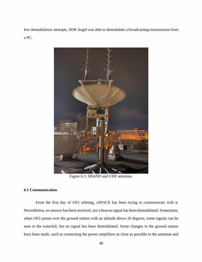
48
few demodulation attempts, SDR Angel was able to demodulate a broadcasting transmission from
a PC.
Figure 6.3: SBAND and UHF antennas.
6.1 Communication
From the first day of OF2 orbiting, cSPACE has been trying to communicate with it.
Nevertheless, no answer has been received, nor a beacon signal has been demodulated. Sometimes,
when OF2 passes over the ground station with an altitude above 20 degrees, some signals can be
seen in the waterfall, but no signal has been demodulated. Some changes in the ground station
have been made, such as connecting the power amplifiers as close as possible to the antennas and

49
implementing digital and analog filters for the exact frequencies needed for communications with
the satellite. Unfortunately, none of this has resulted in a successful communication with the
satellite. Also, the place of the ground station is not really favorable, because non-negligible noise
has been detected in the exact frequency OF2 operates. Testing has started using a LimeSDR
simulating OF2 transmissions from Scenic Drive, near the UTEP main campus, but no signal has
been received. In Bulgaria, EnduroSat has tracked OF2 and received beacon signals with OF2’s
unique id code. Also, CalPoly has been able to demodulate signals from OF2 decoding
successfully the “Hello World” beacon signal from it. Moreover, amateur people from the
SatNOGS community have reported receiving beacon signals from OF2 from different parts of the
world including England, Switzerland, Mexico, Greece, Indonesia, and Holland. Results of these
observations report that the satellite usually transmits beacon signals every 5 seconds. Then it waits
for a minute and continues with beacon signals. This means that the code in the satellite is working
properly. Unfortunately, the only ground station with the license to communicate with OF2 is
cSETR. Until today the cSPACE team is still working on how to communicate with OF2.

50
Chapter 7: Conclusions and Future Work
Development of the project is continuing. Due to the situation of the cSPACE ground
station, the OF2 experiment has not been run. Also, no pictures have been taken of the experiment
and the SBAND antenna has not been tested yet. However, updates will be done to the ground
station until it is able to receive signals from OF2. As long as beacon signals are reported from
OF2 around the world, there is still opportunity to communicate with it.
Also, OF2 has created opportunities for different new projects. There is already a project
nicknamed OF3 that will run a robotic arm in space. Also, there is another project nicknamed
OFX-CG that consists of a 1U CubeSat that will be propelled using cold-gas pressure. And a more
ambitious project is under way for a small satellite orbiting in geostationary transfer orbit (GTO)
thanks to ULA. The OF2 project also provided a lot of experience to the team. Thanks to
presentations given, more investors got interested in CubeSat projects from UTEP. The last lesson
learned from a presentation was during a visit from CalPoly members. During a tour of the
cSPACE ground station, one of the visitors recommended to have power amplifiers as close as
possible to the antennas to reduce noise as much as possible. This greatly improved data received
during operation.
There is also plenty of lessons learned that will not be repeated in future projects. A good
lesson learned is that it is necessary to have at least two CubeSats per project. An engineering unit,
and a flight unit. The purpose of the engineering unit is to simulate and analyze the behavior of
the flight unit on the ground to obtain better conclusions of the behavior of the satellite. Also, the
ground station can be used to simulate transmissions from space adding attenuators to the small
satellites. Another important lesson learned is that every part of the satellite needs to be tested in
an environment that simulates as close as possible the actual environment that the satellite is going
to confront. In 2016, NASA announced that almost every one of two small satellites failed [11].
Moreover, the probabilities of failure increase when it is the first satellite designed by a university.

51
Figure 7.1: Poster used for presenting the OF2 project during a visit from CalPoly
members.
Once a presentation about OF2 was given to employees of Lockheed Martin. One of the
guests said to the OF2 team that if its beacon signals were being received, the team can “pop up
the champagne and celebrate,” because the probabilities were against the project. OF2 should be
considered at least a partial success because it was an accelerated training experience for the team
and third parties all over the world have received proofs that the satellite is working. Later on,
when cSPACE is able to communicate with OF2, experiments may be run and additional
successful results will be presented.

52
Figure 7.2: Members of OF2 team in clean room.
Figure 7.3: Dr. Joel Quintana and Eduardo Macias Zugasti,
two of the OF2 team members in Nanoracks.

53
References
[1] NASA’s Voyager 2 Probe Enters Interstellar Space, Retrieved from
https://voyager.jpl.nasa.gov/mission/timeline/#event-nasas-voyager-2-probe-enters-interstellar-
sace.
[2] CubeSat 101 Basic Concepts and Processes for First-Time CubeSat Developers,
Retrieved from https://www.nasa.gov/directorates/heo/home/CubeSats_initiative.
[3] Valvano, J. 2015. Embedded Systems: Introduction to the MSP432 Microcontroller.
[4] Billah, Kazi Md Masum, "Characterization Of Electrically Conductive Inks In Simulated
Space Environment" (2017). Open Access Theses & Dissertations. 413. Retrieved from
https://digitalcommons.utep.edu/open_etd/413.
[5] Felker, N. 2017. Building MemSat: A CubeSat for Testing Resistive Memory. IEEE
Sensors Application Symposium.
[6] Khurshid, K. 2013. A survey of camera modules for CubeSats – Design of Imaging
payload of ICUBE-1. IEEE.
[7] Perez, P. 2019. Development and Environmental Testing of a Single-axis Printer Inside a
1U CubeSat for On Orbit Servicing Repairs in Low Earth Orbit.
[8] Ünsalan, C. 2015. Programmable Microcontrollers. McGraw Hill.
[9] Prata, S. 2014. C Primer Plus. Pearson Education.
[10] Macias-Zugasti, E., Caldelas, A., Quintana, J., “OF II Payload Control,” Proceedings of
the Southwest Emerging Technology Symposium, El Paso, TX, 2019.
[11] Small Satellite Mission Failure Rates. Retrieved from
https://ntrs.nasa.gov/archive/nasa/casi.ntrs.nasa.gov/20190002705.pdf.

54
Glossary
CMOS Complementary Metal Oxide Semiconductor
COTS Commercial-Off-The-Shelf
CPU Control Processing Unit
cSETR Center for Space Exploration and Technology Research
DC Direct Current
EPS Electric Power System
FPGA Field Programmable Gate Array
GPIO General Purpose Input Output
GPO General Purpose Output
GPS Global Positioning System
IC Integrated Circuit
IDE Integrated Development Environment
ISS International Space Station
I2C Inter-integrated circuit
LUP Latch Up
MOSI Master Out Slave In
MISO Master In Slave Out
OBC On-Board Computer
OF2 Orbital Factory 2
PCB Printed Circuit Board
RTC Real Time Clock

55
RTOS Real Time Operating System
SCL Source Clock
SDA Source Data
SPI Serial Peripheral Interface
UART Universal Asynchronous Receiver Transmitter
UHF Ultra-High Frequency

56
Vita
Eduardo Macias Zugasti attended the University of Texas at El Paso, where he received a
Bachelor of Science in Electrical Engineering in 2018. Deciding to learn more about embedded
systems, he continued his studies with a Master Degree in Electrical Engineering. At the end of
his first graduate semester, he was hired for a research opportunity at UTEP’s NASA MIRO Center
for Space Exploration and Technology Research. From the beginning, he was placed in the
CubeSats team focused on the payload design and the OBC coding for the first small satellite that
UTEP was going to launch, the OF2. After OF2 was launched, Macias Zugasti started to work in
another CubeSat project which works with cold gas by designing the control unit. Macias Zugasti
also worked as a teaching assistant for the class “Introduction to Thermodynamic Fluids” in 2019.
Also, Macias Zugasti has participated in different conferences and he has presented at the local
Southwest Emerging Technology Symposium.
After graduation, Macias Zugasti plans to apply for a Ph.D. program and continue with his
studies by focusing his research in embedded systems for space exploration devices.