Oxyacetylene Cutting An Overview to the Process and Experience.
Introduction
Thermoplastic composites reinforced with continuousfibers have been studied in a wide variety of applications, in-cluding commercial with low cost involved and engineering,and found to have high benefits (Refs. 1–3). In comparisonwith aerospace thermosets, the main advantages of fiber-reinforced thermoplastic composites, such as polyphenylenesulfide (PPS) and polyetherimide (PEI), are in the fact thatthese materials can be stored at room temperature, allowing
for faster cycle times in the manufacture of pressed parts,and have higher efficiency in the welding assembly (Refs. 4,5). In addition, thermoplastic composites offer many inter-esting features, such as high fracture toughness, high dam-age tolerance, reprocessing, and lower recycling and storagecosts (Refs. 6, 7). Among the most used thermoplastic polymers as a ma-trix for composites, PEI stands out. Polyetherimides arehigh-performance amorphous thermoplastics with excellentmechanical, thermal, and chemical properties, even at hightemperatures (Refs. 8, 9). Welding composite materials hasadditional significant advantages over traditional joiningmethods (adhesives and mechanical fixing), given reducedassembly time without increasing weight. Bonding using ad-hesives is time-consuming, and volatile organic solvents in-volve problems that include a possible risk to the health ofoperators. In addition, welding is able to overcome the limi-tations related to the adhesive and avoid the weight gain ofa structure assembled by mechanical fixation (Refs. 10, 11). Different welding processes have been developed for sev-eral applications and procedures. The main processes forjoining thermoplastic composite materials are ultrasonicwelding (USW), resistance welding (RW), and inductionwelding (IW) (Refs. 10, 12, 14). However, despite the great advantages and ample infor-mation described in the literature for these main weldingprocesses for composites, they have some disadvantages.Electrical RW and IW require relatively long welding cycles(Refs. 17, 19), and IW uses expensive equipment (Ref. 16).In USW, there is difficulty in automating the process (Ref.16), and it has a limited welding area (Ref. 12). Welding bonding techniques can be classified accordingto the technology used to generate heating (Refs. 20, 21).There are several processes that are used for welding ther-moplastics. Among these techniques, the hot gas processuses an electric heater to heat the gas and direct it to thewelding region. Also, in search of new welding methods, theoxyfuel gas welding process has been viable, because in addi-tion to its similarity to conventional methods of hot gaswelding, this method is inexpensive and more versatile, as itdoes not require electricity (Refs. 5, 14, 22). During the process, voids may form in welded compos-
WELDING RESEARCH
Development of the Oxyacetylene WeldingProcess for PEI/Glass Fiber Laminates
The optimization of welding parameters was performed using complete factorial planning 22, with time and distance of the flame as variables
BY V. S. OLIVEIRA, R. R. LUCAS, T. P. CARVALHO, L. F. MARQUES, J. F. REIS, A. B. R. M. ABRAHÃO, AND E. C. BOTELHO
ABSTRACT The technology for joining thermoplastics through weld-ing offers numerous advantages over mechanical joining.Currently, the joining of composite parts with weight reduc-tion and cost savings is being developed to improve aircraftperformance. This paper proposes the use of oxygen-acetylene as a process for bonding composite materials.Oxyacetylene welding is a simple and economical methodthat can be suitable for polymeric materials. The advantageof applying this technique is a more accessible processthat is composed of a portable system with low cost. Inevaluating the welding efficiency for composite materials,the lap shear strength (LSS) mechanical test stands outamong the most referenced essays in the literature. Thiswork aimed to study the development of oxyacetyleneflame welding as well as the optimization of welding pa-rameters for polyetherimide/glass fiber composite. The op-timization was performed using complete factorial planning22 as a tool, and the variables studied were time and dis-tance of the flame. With the optimized condition set as theresponse variable with the highest lap shear value, thejoints obtained were measured for their quality by means ofend-notched flexure mechanical testing, thermal analysis,and fracture analysis after LSS testing using optical andelectronic microscopy.
KEYWORDS• Composites • Factorial Planning • Hybrid Welding• Oxyacetylene • Manufacturing • Aluminum
WELDING JOURNAL / APRIL 2021, VOL. 100142-s
https://doi.org/10.29391/2021.100.012
Layout_Oliveira Supp 202058 April 21.qxp_Layout 1 3/3/21 5:37 PM Page 142
ites, leading to weld line failures. This may be related to thepresence of volatile polymer matrix or weld waste gases, re-sulting in delamination of the composite (Refs. 23, 25).Temperature and pressure control during the weldingprocess are of great importance to avoid the formation ofvoids in the welded composites (Refs. 26, 27). However, in-vestigating the presence of voids in the welded material is agood indicator of welding quality by assessing whether theadhesion process was effective. This article presents the development and optimizationof parameters for welding glass fiber (GF)/PEI compositesvia oxyacetylene flame (oxyacetylene welding process, alsoknown as oxyfuel gas welding). The welding parameterswere evaluated by experimental planning. The coupons sub-mitted from the oxyacetylene welding process were charac-terized by LSS and end-notched flexure (ENF) tests, to eval-uate the failure mode II. The morphology of the fracture re-sulting from the mechanical tests was evaluated by opticaland scanning electron microscopy.
Materials and Methods
Laminates
The laminate used in this work was processed and sup-plied by Toray Advanced Composites. The GF/PEI compositefabric laminate was prepared with glass fiber 8HS style, inthe configuration of (0/90)5s, containing approximately 50%in volume of reinforcement, providing a final thickness be-tween 2.0 and 3.5 mm.
Oxyacetylene Welding Process
The process selected for this study was welding by oxy-acetylene gas, due to its versatility and easy handling. It alsodoes not require an electrical source and can be welded auto-genously. This process is known to have three types offlame: fuel, neutral, and oxidant, each of which can be ad-justed by combining gas flow or noting the appearance of
the gas. It is noteworthy that some literature defends thedefinition of these flames by a certain flow value and othersby appearance of the flame (Ref. 20). In this work, the flametype was defined by the visual appearance of the flame. Thefirst sample was welded with the fuel flame, which is ac-quired with more acetylene than oxygen, and the appear-ance is an elongated orange profile. However, in this case,immediately after welding, it was observed that the flameleft a layer of soot that interfered with the temperaturemeasurement. Thus, the type of flame used in this weldingwas the oxidant. With a flow rate of 0.5 m³/s of acetyleneand 1.0 m³/s of oxygen, it was characterized by excess oxy-gen in relation to acetylene and the higher temperature ofthe flames. With the optimization of gas flows, the oxidiz-ing flame acquired a blue profile with a characteristic noise.At the end of welding with this flame, the absence of sootwas noted, and as oxygen increased the flame temperature,the welding time decreased.
Development of the Welding Device
An important point for welding in advanced polymer ma-trix composites is the welding temperature range (weldingwindow). The PEI has a degradation temperature start of ap-proximately 460°C (Ref. 26). The glass transition tempera-ture (Tg) is approximately 217°C (Ref. 27), and for this, thetemperature was measured during and after welding withthe use of a Lasergrip GM400 infrared thermometer with acapacity of –50° to 400°C, with the temperature varying be-tween 230° and 250°C. For welding to occur, this materialmust be subjected to temperatures above its Tg; however, itmust not reach its temperature of thermal degradation dur-ing the process. Between these ranges, the polymer softensand solidifies, causing a union and thus forming a joint. Ad-ditionally, to guarantee the quality and efficiency of com-posite material joints obtained by welding, it is necessary toensure the heating does not harm the polymeric matrix, asthis would be compromising the mechanical property of thematerial. In this work, for the execution of welding usingthe oxyacetylene process, a device was first built with refrac-
WELDING RESEARCH
APRIL 2021 / WELDING JOURNAL 143-s
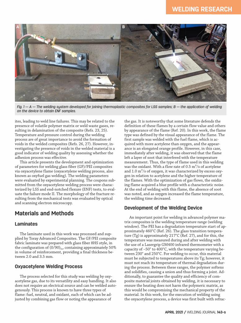
A B
Fig. 1 — A — The welding system developed for joining thermoplastic composites for LSS samples; B — the application of weldingon the device to obtain ENF samples.
Layout_Oliveira Supp 202058 April 21.qxp_Layout 1 3/3/21 5:37 PM Page 143
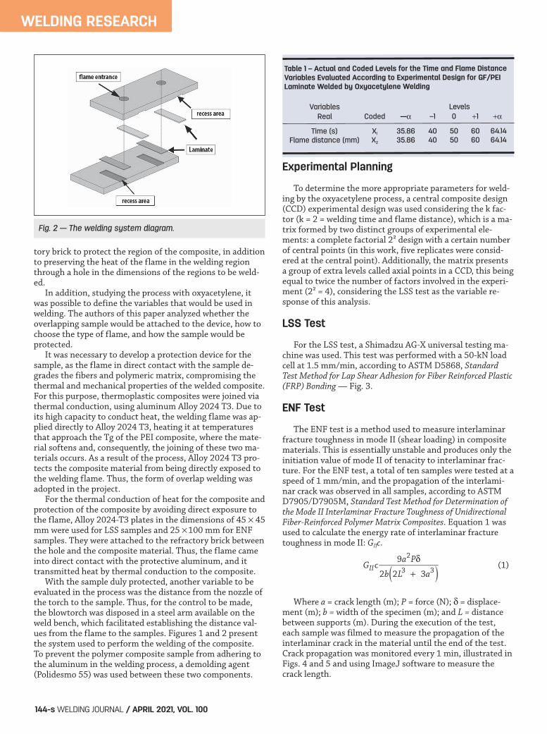
tory brick to protect the region of the composite, in additionto preserving the heat of the flame in the welding regionthrough a hole in the dimensions of the regions to be weld-ed. In addition, studying the process with oxyacetylene, itwas possible to define the variables that would be used inwelding. The authors of this paper analyzed whether theoverlapping sample would be attached to the device, how tochoose the type of flame, and how the sample would be protected. It was necessary to develop a protection device for thesample, as the flame in direct contact with the sample de-grades the fibers and polymeric matrix, compromising thethermal and mechanical properties of the welded composite.For this purpose, thermoplastic composites were joined viathermal conduction, using aluminum Alloy 2024 T3. Due toits high capacity to conduct heat, the welding flame was ap-plied directly to Alloy 2024 T3, heating it at temperaturesthat approach the Tg of the PEI composite, where the mate-rial softens and, consequently, the joining of these two ma-terials occurs. As a result of the process, Alloy 2024 T3 pro-tects the composite material from being directly exposed tothe welding flame. Thus, the form of overlap welding wasadopted in the project. For the thermal conduction of heat for the composite andprotection of the composite by avoiding direct exposure tothe flame, Alloy 2024-T3 plates in the dimensions of 45 45mm were used for LSS samples and 25 100 mm for ENFsamples. They were attached to the refractory brick betweenthe hole and the composite material. Thus, the flame cameinto direct contact with the protective aluminum, and ittransmitted heat by thermal conduction to the composite. With the sample duly protected, another variable to beevaluated in the process was the distance from the nozzle ofthe torch to the sample. Thus, for the control to be made,the blowtorch was disposed in a steel arm available on theweld bench, which facilitated establishing the distance val-ues from the flame to the samples. Figures 1 and 2 presentthe system used to perform the welding of the composite.To prevent the polymer composite sample from adhering tothe aluminum in the welding process, a demolding agent(Polidesmo 55) was used between these two components.
Experimental Planning
To determine the more appropriate parameters for weld-ing by the oxyacetylene process, a central composite design(CCD) experimental design was used considering the k fac-tor (k = 2 = welding time and flame distance), which is a ma-trix formed by two distinct groups of experimental ele-ments: a complete factorial 2² design with a certain numberof central points (in this work, five replicates were consid-ered at the central point). Additionally, the matrix presentsa group of extra levels called axial points in a CCD, this beingequal to twice the number of factors involved in the experi-ment (2² = 4), considering the LSS test as the variable re-sponse of this analysis.
LSS Test
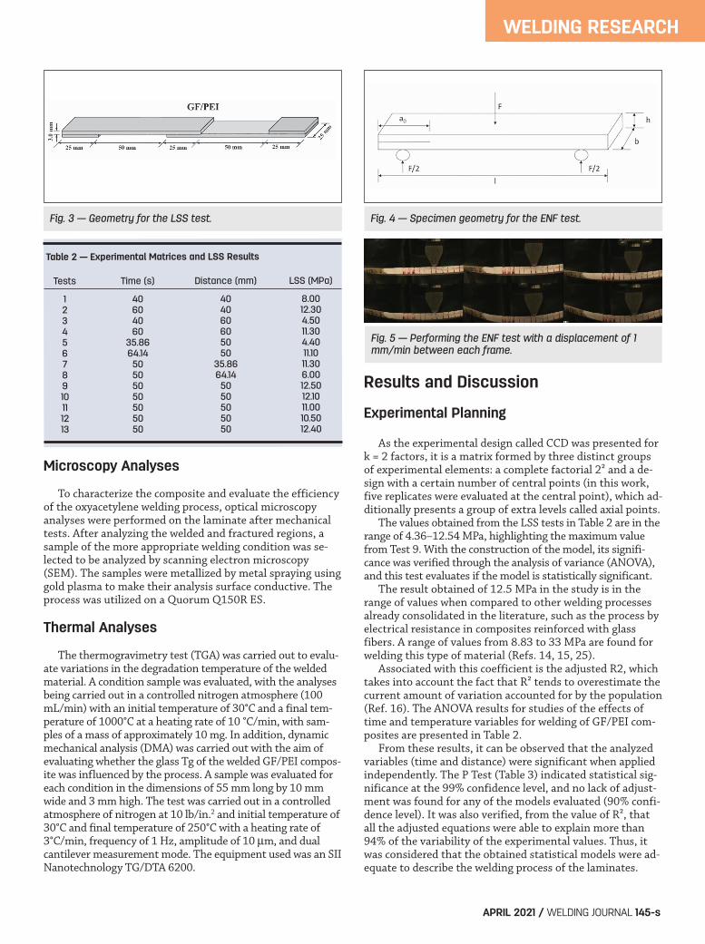
For the LSS test, a Shimadzu AG-X universal testing ma-chine was used. This test was performed with a 50-kN loadcell at 1.5 mm/min, according to ASTM D5868, StandardTest Method for Lap Shear Adhesion for Fiber Reinforced Plastic(FRP) Bonding — Fig. 3.
ENF Test
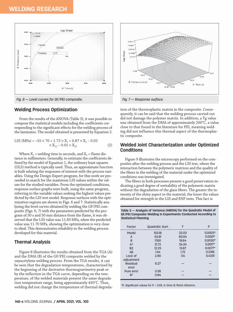
The ENF test is a method used to measure interlaminarfracture toughness in mode II (shear loading) in compositematerials. This is essentially unstable and produces only theinitiation value of mode II of tenacity to interlaminar frac-ture. For the ENF test, a total of ten samples were tested at aspeed of 1 mm/min, and the propagation of the interlami-nar crack was observed in all samples, according to ASTMD7905/D7905M, Standard Test Method for Determination ofthe Mode II Interlaminar Fracture Toughness of UnidirectionalFiber-Reinforced Polymer Matrix Composites. Equation 1 wasused to calculate the energy rate of interlaminar fracturetoughness in mode II: GIIc.
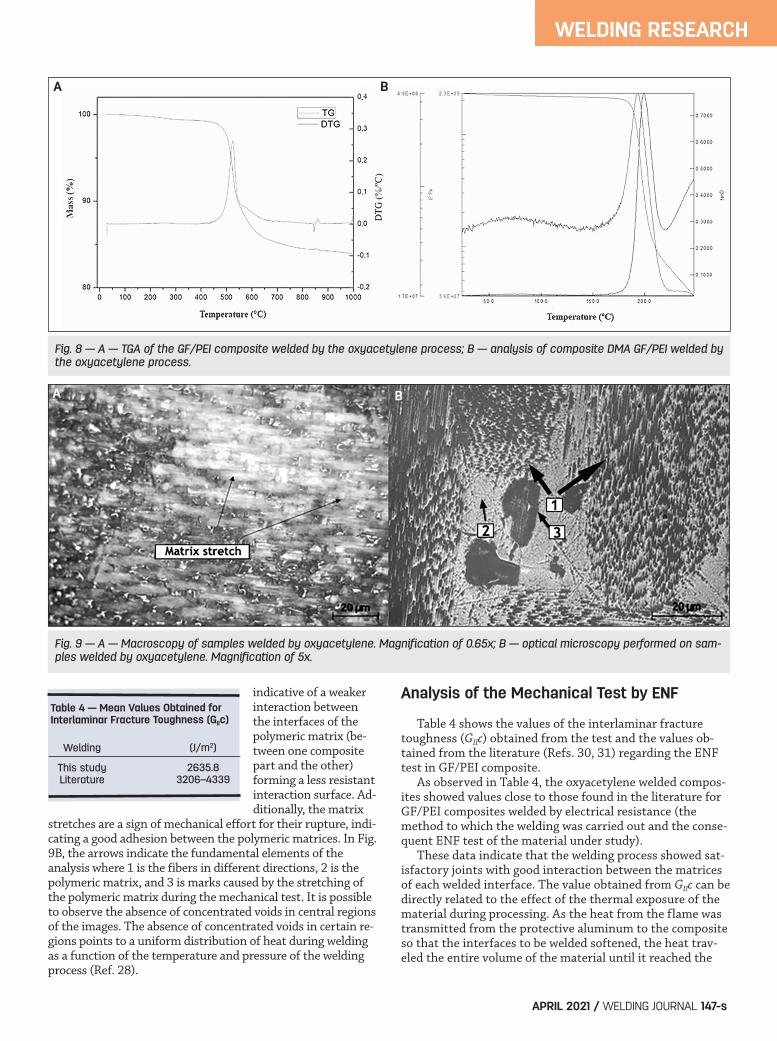
Where a = crack length (m); P = force (N); = displace-ment (m); b = width of the specimen (m); and L = distancebetween supports (m). During the execution of the test,each sample was filmed to measure the propagation of theinterlaminar crack in the material until the end of the test.Crack propagation was monitored every 1 min, illustrated inFigs. 4 and 5 and using ImageJ software to measure thecrack length.
GIIc9a2P�
2b 2L3 + 3a3( ) (1)
WELDING RESEARCH
WELDING JOURNAL / APRIL 2021, VOL. 100144-s
Fig. 2 — The welding system diagram.
Table 1 – Actual and Coded Levels for the Time and Flame DistanceVariables Evaluated According to Experimental Design for GF/PEILaminate Welded by Oxyacetylene Welding
Variables LevelsReal Coded — –1 0 +1 +
Time (s) X1 35.86 40 50 60 64.14 Flame distance (mm) X2 35.86 40 50 60 64.14
Layout_Oliveira Supp 202058 April 21.qxp_Layout 1 3/3/21 5:37 PM Page 144
Microscopy Analyses
To characterize the composite and evaluate the efficiencyof the oxyacetylene welding process, optical microscopyanalyses were performed on the laminate after mechanicaltests. After analyzing the welded and fractured regions, asample of the more appropriate welding condition was se-lected to be analyzed by scanning electron microscopy(SEM). The samples were metallized by metal spraying usinggold plasma to make their analysis surface conductive. Theprocess was utilized on a Quorum Q150R ES.
Thermal Analyses
The thermogravimetry test (TGA) was carried out to evalu-ate variations in the degradation temperature of the weldedmaterial. A condition sample was evaluated, with the analysesbeing carried out in a controlled nitrogen atmosphere (100mL/min) with an initial temperature of 30°C and a final tem-perature of 1000°C at a heating rate of 10 °C/min, with sam-ples of a mass of approximately 10 mg. In addition, dynamicmechanical analysis (DMA) was carried out with the aim ofevaluating whether the glass Tg of the welded GF/PEI compos-ite was influenced by the process. A sample was evaluated foreach condition in the dimensions of 55 mm long by 10 mmwide and 3 mm high. The test was carried out in a controlledatmosphere of nitrogen at 10 lb/in.2 and initial temperature of30°C and final temperature of 250°C with a heating rate of3°C/min, frequency of 1 Hz, amplitude of 10 m, and dualcantilever measurement mode. The equipment used was an SIINanotechnology TG/DTA 6200.
Results and Discussion
Experimental Planning
As the experimental design called CCD was presented fork = 2 factors, it is a matrix formed by three distinct groupsof experimental elements: a complete factorial 2² and a de-sign with a certain number of central points (in this work,five replicates were evaluated at the central point), which ad-ditionally presents a group of extra levels called axial points. The values obtained from the LSS tests in Table 2 are in therange of 4.36–12.54 MPa, highlighting the maximum valuefrom Test 9. With the construction of the model, its signifi-cance was verified through the analysis of variance (ANOVA),and this test evaluates if the model is statistically significant. The result obtained of 12.5 MPa in the study is in therange of values when compared to other welding processesalready consolidated in the literature, such as the process byelectrical resistance in composites reinforced with glassfibers. A range of values from 8.83 to 33 MPa are found forwelding this type of material (Refs. 14, 15, 25). Associated with this coefficient is the adjusted R2, whichtakes into account the fact that R² tends to overestimate thecurrent amount of variation accounted for by the population(Ref. 16). The ANOVA results for studies of the effects oftime and temperature variables for welding of GF/PEI com-posites are presented in Table 2. From these results, it can be observed that the analyzedvariables (time and distance) were significant when appliedindependently. The P Test (Table 3) indicated statistical sig-nificance at the 99% confidence level, and no lack of adjust-ment was found for any of the models evaluated (90% confi-dence level). It was also verified, from the value of R², thatall the adjusted equations were able to explain more than94% of the variability of the experimental values. Thus, itwas considered that the obtained statistical models were ad-equate to describe the welding process of the laminates.
WELDING RESEARCH
APRIL 2021 / WELDING JOURNAL 145-s
Fig. 3 — Geometry for the LSS test. Fig. 4 — Specimen geometry for the ENF test.
Table 2 — Experimental Matrices and LSS Results
Tests Time (s) Distance (mm) LSS (MPa)
1 40 40 8.00 2 60 40 12.30 3 40 60 4.50 4 60 60 11.30 5 35.86 50 4.40 6 64.14 50 11.10 7 50 35.86 11.30 8 50 64.14 6.00 9 50 50 12.50 10 50 50 12.10 11 50 50 11.00 12 50 50 10.50 13 50 50 12.40
Fig. 5 — Performing the ENF test with a displacement of 1mm/min between each frame.
Layout_Oliveira Supp 202058 April 21.qxp_Layout 1 3/3/21 5:37 PM Page 145
Welding Process Optimization
From the results of the ANOVA (Table 3), it was possible tocompose the statistical models including the coefficients cor-responding to the significant effects for the welding process ofthe laminates. The model obtained is presented by Equation 2.
LSS (MPa) = –55 70 + 1.72 X1 + 0.87 X2 – 0.02 X12 – 0.01 X22 (2)
Where X1 = welding time in seconds, and X2 = flame dis-tance in millimeters. Generally, to estimate the coefficients de-fined by the model of Equation 1, the ordinary least squares(OLS) method is typically used. Thus, an approximate functionis built relating the responses of interest with the process vari-ables. Using the Design-Expert program, for this work we pro-ceeded to search for the maximum LSS values within the val-ues for the studied variables. From the optimized conditions,response surface graphs were built, using the same program,referring to the variable values seeking the highest values pre-dicted by the LSS test model. Response surfaces with the opti-mization regions are shown in Figs. 6 and 7. Statistically ana-lyzing the level curves obtained by welding the GF/PEI com-posite (Figs. 6, 7) with the parameters predicted by the pro-gram of 50 s and 50 mm distance from the flame, it was ob-served that the LSS value was 11.83 MPa, when the predictedvalue was 11.70 MPa, showing the optimization is very closeto ideal. This demonstrates reliability in the welding processdeveloped for this material.
Thermal Analysis
Figure 8 illustrates the results obtained from the TGA (A)and the DMA (B) of the GF/PEI composite welded by theoxyacetylene welding process. From the TGA results, it canbe seen that the degradation temperatures, characterized bythe beginning of the derivative thermogravimetry peak orby the inflection in the TGA curve, depending on the tem-perature, of the welded materials present the same degrada-tion temperature range, being approximately 450°C. Thus,welding did not change the temperature of thermal degrada-
tion of the thermoplastic matrix in the composite. Conse-quently, it can be said that the welding process carried outdid not damage the polymer matrix. In addition, a Tg valuewas obtained from the DMA of approximately 200°C, a valueclose to that found in the literature for PEI, meaning weld-ing did not influence this thermal aspect of the thermoplas-tic composite.
Welded Joint Characterization under OptimizedConditions
Figure 9 illustrates the microscopy performed on the com-posites after the welding process and the LSS test, where theinteraction between the polymeric matrices and the quality ofthe fibers in the welding of the material under the optimizedconditions was investigated. The fibers in both processes present a good preservation in-dicating a good degree of wettability of the polymeric matrixwithout the degradation of the glass fibers. The greater the in-tensity of the shiny aspect in the material, the lower the valuesobtained for strength in the LSS and ENF tests. This fact is
WELDING RESEARCH
WELDING JOURNAL / APRIL 2021, VOL. 100146-s
Fig. 6 — Level curves for GF/PEI composite. Fig. 7 — Response surface.
Table 3 — Analysis of Variance (ANOVA) for the Quadratic Model ofGF/PEI Composite Welding in Experiments Conducted According to Statistical Planning
Factor Quadratic Sum F P
Model 103.18 23.03 0.0003* A 53.81 60.04 0.0001* B 17.60 19.64 0.0030* A² 21.72 24.24 0.0017* B2 12.25 13.67 0.0077* AB 1.54 1.72 0.2316 Lack of 2.90 1.14 0.4331 adjustment Residual 6.27 — — error Pure error 3.38 — — R2 0.94 — —
*P: Significant values for P 0.05, A: time; B: flame distance.
Layout_Oliveira Supp 202058 April 21.qxp_Layout 1 3/3/21 5:37 PM Page 146
indicative of a weakerinteraction betweenthe interfaces of thepolymeric matrix (be-tween one compositepart and the other)forming a less resistantinteraction surface. Ad-ditionally, the matrix
stretches are a sign of mechanical effort for their rupture, indi-cating a good adhesion between the polymeric matrices. In Fig.9B, the arrows indicate the fundamental elements of theanalysis where 1 is the fibers in different directions, 2 is thepolymeric matrix, and 3 is marks caused by the stretching ofthe polymeric matrix during the mechanical test. It is possibleto observe the absence of concentrated voids in central regionsof the images. The absence of concentrated voids in certain re-gions points to a uniform distribution of heat during weldingas a function of the temperature and pressure of the weldingprocess (Ref. 28).
Analysis of the Mechanical Test by ENF
Table 4 shows the values of the interlaminar fracturetoughness (GIIc) obtained from the test and the values ob-tained from the literature (Refs. 30, 31) regarding the ENFtest in GF/PEI composite. As observed in Table 4, the oxyacetylene welded compos-ites showed values close to those found in the literature forGF/PEI composites welded by electrical resistance (themethod to which the welding was carried out and the conse-quent ENF test of the material under study). These data indicate that the welding process showed sat-isfactory joints with good interaction between the matricesof each welded interface. The value obtained from GIIc can bedirectly related to the effect of the thermal exposure of thematerial during processing. As the heat from the flame wastransmitted from the protective aluminum to the compositeso that the interfaces to be welded softened, the heat trav-eled the entire volume of the material until it reached the
WELDING RESEARCH
APRIL 2021 / WELDING JOURNAL 147-s
Table 4 — Mean Values Obtained forInterlaminar Fracture Toughness (GIIc)
Welding (J/m2)
This study 2635.8 Literature 3206–4339
Fig. 8 — A — TGA of the GF/PEI composite welded by the oxyacetylene process; B — analysis of composite DMA GF/PEI welded bythe oxyacetylene process.
Fig. 9 — A — Macroscopy of samples welded by oxyacetylene. Magnification of 0.65x; B — optical microscopy performed on sam-ples welded by oxyacetylene. Magnification of 5x.
A B
A B
Layout_Oliveira Supp 202058 April 21.qxp_Layout 1 3/3/21 5:37 PM Page 147
interfaces in contact under pressure. This process resultedin a thermal expansion of both the matrix and the fibersand, because they are dissimilar materials, they presenteddifferent thermal expansion coefficients. This may result inthe appearance of microdefect principles such as pores andmicrocracks, favoring the appearance and propagation of in-terlaminate cracks during the mechanical request of thetest. Figure 10 shows results from scanning electron mi-croscopy of samples welded by oxyacetylene. From the obtained images it is possible to observe that thefracture surfaces of both figures are rich in fractographic as-pects, with the presence of flaws from the thermoplastic ma-trix. The figures show cusps from the shear between thefiber/matrix regions. Also observed are regions of detachedand broken fibers along with river marks in regions with ahigher volume of the polymeric matrix. These factors are indi-cators of intralaminar failures. The river marks were formedby several uneven crack planes directed to a single plane whilethe fault propagated in the material. The river marks con-verged in a direction where the crack had grown. It is also pos-sible to notice fiber print marks on the polymeric matrix andplastic deformations of the matrix, resulting from the vis-coelastic characteristic of the polymeric matrix. In addition,Fig. 10 shows a good consolidation between the welded jointsthrough the broken fibers with the presence of a thin coveringof the polymer matrix. However, there was a significant reduc-tion in the polymer matrix covering the broken glass fiberwires and the number of strands that were detached with theabsence of a polymeric matrix, indicating less interaction be-tween the welded matrices (Ref. 31). This fact indicates aslightly weaker interfacial adhesion of the welding processwhen compared to the other process, corroborating with thedata obtained through mechanical tests.
Conclusion
Based on the results obtained in this work, it is possibleto establish a better statistical model to evaluate the mostsuitable parameters for the welding of GF/PEI composite bythe oxyacetylene process. With welding parameters of 50 sat a distance of 50 mm, a LSS value of 12.50 MPa was ac-
quired, which is an interesting value in relation to otherprocesses with the same material. In addition, the adapta-tion of the refractory device provided suitable welding forthe composite without degradation of the sample, as provenby the microscopic and visual analysis of the laminate. Frac-tography showed failure mechanisms in oxyacetylene weld-ing, obtaining results rich in details in regions with higherdensity of the polymeric matrix, such as cusps, river marksindicating the direction of failure propagation, plastic defor-mation of the matrix, glass fiber detachment and breakage,and printing marks of metal mesh and glass fibers in thepolymer matrix. These fractographic aspects are indicatorsof intralaminar failure, characterizing a good interactionand molecular diffusion of the polymer between the inter-faces in contact.
This study was financed by the FAPESP (São Paulo ResearchFoundation) under project 2017/16970-0 and CNPq under project303224/2016-9.
1. Botelho, E. C., Scherbakoff, N., Rezende, M. C., Kawamoto, A.M., and Sciamareli, J. 2001. Synthesis of polyamide 6/6 by interfa-cial polycondensation with the simultaneous impregnation of car-bon fibers. Macromolecules 34: 3367–3375. DOI: 10.1021/ma000902k
2. Khan, M. A., Syed, A. K., Ijaz, H., and Shah, R. M. B. R. 2018.Experimental and numerical analysis of flexural and impact behav-iour of glass/pp sandwich panel for automotive structural applica-tions. Advanced Composite Materials 27: 367–386. DOI: 10.1080/09243046.2017.1396199
3. Okabe, T., Motani, T., Nishikawa, M., and Hashimoto, M.2012. Numerical simulation of microscopic damage and strengthof fiber-reinforced plastic composites. Advanced Composite Materi-als 21: 147–163. DOI: 10.1080/09243046.2012.688495
4. Fischer, F. J. C., Beyrle, M., Thellmann, A. H., Endrass, M.,
WELDING RESEARCH
WELDING JOURNAL / APRIL 2021, VOL. 100148-s
Fig. 10 — SEM analysis on fractured ENF samples of composite GF/PEI. A — Magnification 200x; B — magnification of 1000x.
References
Acknowledgments
A B
Layout_Oliveira Supp 202058 April 21.qxp_Layout 1 3/3/21 5:37 PM Page 148
Stefani, T., Gerngross, T., and Kupke, M. 2017. Corrugated com-posites: Production-integrated quality assurance in carbon fiber re-inforced thermoplastic sine wave beam production. Advanced Man-ufacturing: Polymer and Composites Science 3: 10–20. DOI: 10.1080/20550340.2017.1283100
5. Tafreshi, O. A., Hoa, S. V., Shadmehri, F., Minh, D., and Rosca,D. 2019. Heat transfer analysis of automated fiber placement ofthermoplastic composites using a hot gas torch. Advanced Manufac-turing: Polymer and Composites Science 5: 206–223. DOI: 10.1080/20550340.2019.1686820
6. Zhang, X., Lu, C., and Liang, M. 2011. Preparation of thermo-plastic vulcanizates based on waste crosslinked polyethylene andground tire rubber through dynamic vulcanization. Journal of Ap-plied Polymer Science 122(3): 2110–2120. DOI: 10.1002/app.34293
7. Zammar, I., Huq, M. S., Mantegh, I., Yousefpour, A., andAhamadi, M. 2017. A three-dimensional transient model for heattransfer in thermoplastic composites during continuous resistancewelding. Advanced Manufacturing: Polymer and Composites Science3(1): 32–41. DOI: 10.1080/20550340.2017.1311094
8. Ramgobin, A., Fontaine, G., and Bourbigot, S. 2019. Thermaldegradation and fire behavior of high performance polymers. Poly-mer Reviews 59(1): 55–123. DOI: 10.1080/15583724.2018.1546736
9. Cacciotti, I., Rinaldi, M., Fabbrizi, J., and Nanni, F. 2019. In-novative polyetherimide and diatomite based composites: Influ-ence of the diatomite kind and treatment. Journal of Materials Re-search and Technology 8(2): 1737–1745. DOI: 10.1016/j.jmrt.2018.12.004
10. Lionetto, F., Pappadà, S., Buccoliero, G., and Maffezzoli, A.2017. Finite element modeling of continuous induction welding ofthermoplastic matrix composites. Materials and Design 120(15):212–221. DOI: 10.1016/j.matdes.2017.02.024
11. Nagatsuka, K., Xiao, B., Wu, L., Natata, K., Saeki, S., Kita-moto, Y., and Iwamoto, Y. 2018. Dissimilar materials joining ofmetal/carbon fibre reinforced plastic by resistance spot welding.Welding International 32(7): 505–512. DOI: 10.1080/01431161.2017.1346889
12. Villegas, I. F., Moser, L., Moser, A., Yousefpour, P., andMitschang, H. E. N. 2013. Process and performance evaluation ofultrasonic, induction and resistance welding of advanced thermo-plastic composites. Journal of Thermoplastic Composite Materials26(8): 1007–1024. DOI: 10.1177/0892705712456031
13. Brassard, D., Dubé, M., and Tavares, J. R. 2019. Resistancewelding of thermoplastic composites with a nanocomposite heat-ing element. Composites Part B: Engineering 165(15): 779–784. DOI:10.1016/j.compositesb.2019.02.038
14. Dubé, M. et al. 2012.Metal mesh heating element size effectin resistance welding of thermoplastic composites. Journal of Com-posite Materials 46(8): 911–918.
15. Pannerselvam, K. et al. 2012. Study on resistance welding ofglass fiber reinforced thermoplastic composites. Materials and De-sign 41: 453–459.
16. Yousefpour, A., Hojjati, M., and Immarigeon, J. P. 2004. Fu-sion bonding/welding of thermoplastic composites. Journal of Ther-moplastic Composite Materials 17(4): 303–341. DOI: 10.1177/0892705704045187
17. Ageorges, C., and Ye, L. 2001. Resistance welding ofmetal/thermoplastic composite joints. Journal of ThermoplasticComposite Materials 14: 449–475. DOI: 10.1106/PN74-QXKH-7XBE-XKF5
18. André, N. M., Goushegir, S. M., Santos, J. F., Canto, L. B.,and Filho, S. T. 2016. Friction spot joining of aluminum Alloy2024-T3 and carbon-fiber-reinforced poly(phenylene sulfide) lami-nate with additional PPS film interlayer: Microstructure, mechani-cal strength and failure mechanisms. Composites Part B: Engineering94: 197–208. DOI: 10.1016/j.compositesb.2016.03.011
19. Mitschang, P., Velthuis, R., and Didi, M. 2013. Induction
spot welding of metal/CFRPC hybrid joints. Advanced EngineeringMaterials 15(9): 804–813. DOI: 10.1002/adem.201200273
20. Palary, G., Shi, H., Levy, A., Le Corre, S., and Villegas, I. F.2018. A study on amplitude transmission in ultrasonic welding ofthermoplastic composites. Composites Part A: Applied Science andManufacturing 113: 339–349. DOI: 10.1016/j.compositesa.2018.07.033
21. Wang, K., Shriver, D., Li, Y., Banu, M., Hu, S. J., Xiao, G.,Arinez, J., and Fan, H. T. 2017. Characterization of weld attributesin ultrasonic welding of short carbon fiber reinforced thermoplas-tic composites. Journal of Manufacturing Processes 29: 124–132.DOI: 10.1016/j.jmapro.2017.07.024
22. Messler, R. W. 2004. Joining of Materials and Structures: FromPragmatic Process to Enabling Technology. London, United Kingdom:Butterworth-Heinemann.
23. Chang, T., Zhan, L., Tan, W., and Li, S. 2017. Void contentand interfacial properties of composite laminates under differentautoclave cure pressure. Composite Interfaces 24(5): 529–540. DOI:10.1080/09276440.2016.1237113
24. Shi, H., Villegas, I. F., Octeau, M. A., Bersee, H. E. N., andYousefpour, A. 2015. Continuous resistance welding of thermo-plastic composites: Modelling of heat generation and heat transfer.Composites Part A: Applied Science and Manufacturing 70: 16–26.DOI: 10.1016/j.compositesa.2014.12.007
25. Warren, K. C., Anido, R. A. L., Freund, A. L., and Dagher, H.J. 2016. Resistance welding of glass fiber reinforced PET: Effect ofweld pressure and heating element geometry. Journal of ReinforcedPlastics and Composites 35(12): 974–985. DOI: 10.1177/0731684416633516
26. Costa, M. L., Rezende, M. C., and de Almeida, S. F. M. 2006.Effect of void content on the moisture absorption in polymericcomposites. Polymer-Plastics Technology and Engineering 45(6): 691–698. DOI: 10.1080/03602550600609549
27. Shi, H., Villegas, I. F., and Bersee, H. E. N. 2017. Analysis ofvoid formation in thermoplastic composites during resistancewelding. Journal of Thermoplastic Composite Materials 30: 1654–1674. DOI: 10.1177/0892705716662514
28. Reis, J. F., Abrahao, A. B. M., Costa, M. L., and Botelho, E. C.2018. Assessment of the interlaminar strength of resistance-welded PEI/carbon fibre composite. Welding International 32(2):149–160. DOI: 10.1080/09507116.2017.1347329
29. Pozegic, T. R., King, S. G., Fotouhi, M., Stolojan, V., Silva, S.R. P., and Hamerton, I. 2019. Delivering interlaminar reinforce-ment in composites through electrospun nanofibres. AdvancedManufacturing: Polymer & Composites Science 5(4): 155–171. DOI:10.1080/20550340.2019.1665226
30. Yuan, Q., Mai, Y. W., Ye, L., and Hou, M. 2001. Resistancewelding of carbon fiber reinforced polyetherimide composite. Jour-nal of Thermoplastic Composite Materials 14(1): 2–19. DOI:10.1106/XF4F-6NEH-9KGN-1Y4R
31. Zenasni, R., Bachir, A. S., Viña, I., Arguelles, A., and Viña, J.2006. Effect of hygrothermomechanical aging on the interlaminarfracture behavior of woven fabric fiber/PEI composite materials.Journal of Thermoplastic Composite Materials 19(4): 385–398. DOI:10.1177/0892705706059743
WELDING RESEARCH
APRIL 2021 / WELDING JOURNAL 149-s
VITÓRIA SIMPLÍCIO OLIVEIRA ([email protected])and ANA BEATRIZ RAMOS MOREIRA ABRAHÃO are with Tech-nology College – FATEC, Pindamonhangaba, Brazil. RAFAELRESENDE LUCAS, TAYENNE PRADO CARVALHO, LUIS FELIPEMARQUES, JONAS FRANK REIS, and EDSON COCCHIERIBOTELHO are with the Department of Materials and Technol-ogy, School of Engineering, São Paulo State University –UNESP, Guaratinguetá, Brazil.
Layout_Oliveira Supp 202058 April 21.qxp_Layout 1 3/3/21 5:37 PM Page 149