Development of Lithium-Sulfur Battery with Cation Exchange ... · PDF file8 Technical Report...
7
8 Technical Report 報 文 ty over 800 mAh g -1 based on the mass of the com- posite 1 . However, the lithium- sulfur (Li- S) battery with the composite still has problems of capacity fad- ing during charge-discharge cycles and low coulom- bic efficiency as well as common Li - S batteries. These are derived from a formation of Li2S with poor reversibility and the migration of the polysulfide which induce continuous redox reaction between pos- itive and negative electrodes so called “polysulfide shuttle”. In order to solve these problems, the sup- pression technology of the formation of Li2S by apply- ing polysulfides into the ether-based electrolyte solu- tion with Li salt of lithium bis(trifluoromethane sulfonyl)imide (LiTFSI) was reported 2 . It is well known that the carbonate-based solvents such as ethylene 1 Introduction Sulfur is the most promising candidate of the posi- tive active material for next-generation batteries with high energy density because of high theoretical specif- ic capacity (1675 mAh g -1 ). However, this material has serious problem of low utilization for the electrochem- ical reaction due to the insulating nature of sulfur and Li2S of its discharge product. We have reported that sulfur-porous carbon composite (SPC) manufactured by filling high content sulfur of 70 mass% into na- no-sized pore of MgO templated carbon showed high utilization of sulfur resulting in high discharge capaci- We have investigated the influence of electrolyte solution for the lithium-sulfur battery with cation exchange membrane as a separator and lithium polysulfide solution in the positive electrode containing elemental sulfur on the charge-discharge performance of the battery. As a result of the investigation, the high concentration of lithium bis(trifluoromethane sulfonyl)imide (LiTFSI) as a Li salt in the solution causes the drastically high internal resist- ance of the battery resulting in the low performance, so that the solution without LiTFSI is found out to be favora- ble to improve the performance of the battery. The battery containing the solution in the positive electrode shows extremely high and stable capacity and high coulombic efficiency. This high and stable capacity is derived from that the polysulfide solution contributes to electrochemical reaction as the active material resulting in suppression of Li2S formation. And the high coulombic efficiency is caused by the fact that the cation exchange membrane pre- vented the migration of polysulfide anion which brings “polysulfide shuttle”. Key words : Lithium ; Sulfur ; Cation exchange membrane separator ; Lithium polysulfide solution Abstract © 2016 GS Yuasa International Ltd., All rights reserved. Development of Lithium-Sulfur Battery with Cation Exchange Membrane Separator and Lithium Polysulfide Solution Kaname Nakajima * Heisuke Nishikawa * Shuji Hitomi * Tokuo Inamasu * * Department Ⅱ, R&D Center
-
Upload
nguyennguyet -
Category
Documents
-
view
214 -
download
1
Transcript of Development of Lithium-Sulfur Battery with Cation Exchange ... · PDF file8 Technical Report...

8
Technical Report
報 文
ty over 800 mAh g-1 based on the mass of the com-posite1. However, the lithium-sulfur (Li-S) battery with the composite still has problems of capacity fad-ing during charge-discharge cycles and low coulom-bic efficiency as well as common Li-S batteries. These are derived from a formation of Li2S with poor reversibility and the migration of the polysulfide which induce continuous redox reaction between pos-itive and negative electrodes so called “polysulfide shuttle”. In order to solve these problems, the sup-pression technology of the formation of Li2S by apply-ing polysulfides into the ether-based electrolyte solu-tion with Li salt of lithium bis(trifluoromethane sulfonyl)imide (LiTFSI) was reported2. It is well known that the carbonate-based solvents such as ethylene
1 Introduction
Sulfur is the most promising candidate of the posi-tive active material for next-generation batteries with high energy density because of high theoretical specif-ic capacity (1675 mAh g-1). However, this material has serious problem of low utilization for the electrochem-ical reaction due to the insulating nature of sulfur and Li2S of its discharge product. We have reported that sulfur-porous carbon composite (SPC) manufactured by filling high content sulfur of 70 mass% into na-no-sized pore of MgO templated carbon showed high utilization of sulfur resulting in high discharge capaci-
We have investigated the influence of electrolyte solution for the lithium-sulfur battery with cation exchange membrane as a separator and lithium polysulfide solution in the positive electrode containing elemental sulfur on the charge-discharge performance of the battery. As a result of the investigation, the high concentration of lithium bis(trifluoromethane sulfonyl)imide (LiTFSI) as a Li salt in the solution causes the drastically high internal resist-ance of the battery resulting in the low performance, so that the solution without LiTFSI is found out to be favora-ble to improve the performance of the battery. The battery containing the solution in the positive electrode shows extremely high and stable capacity and high coulombic efficiency. This high and stable capacity is derived from that the polysulfide solution contributes to electrochemical reaction as the active material resulting in suppression of Li2S formation. And the high coulombic efficiency is caused by the fact that the cation exchange membrane pre-vented the migration of polysulfide anion which brings “polysulfide shuttle”.
Key words : Lithium ; Sulfur ; Cation exchange membrane separator ; Lithium polysulfide solution
Abstract
© 2016 GS Yuasa International Ltd., All rights reserved.
Development of Lithium-Sulfur Battery with Cation Exchange Membrane Separator
and Lithium Polysulfide Solution
Kaname Nakajima* Heisuke Nishikawa* Shuji Hitomi* Tokuo Inamasu*
* Department Ⅱ, R&D Center

9
GS Yuasa Technical Report 2016 年 12 月 第 13巻 第 2号
2.2 Preparation of lithiated cation exchange mem-brane
The cation exchange membrane of Nafion mem-brane in H+ form (Nafion® NRE-212, Dupont) was used as a separator. The Li+ ion exchange for the membrane (Li-Nafion) was carried out by immersing it in a solution of 1.0 M LiOH/H2O : ethanol = 50 : 50 (vol%) at 80℃ for 4 h under stirring. The Li-Nafion was rinsed in boiling deionized water followed by vac-uum drying at 120℃ overnight. After the procedure, Li-Nafion was swollen by DOL : DME = 50 : 50 (vol%)(DOL-DME) at 80℃ for 12 h.2.3 Synthesis of polysulfide (Li2S6) solution
Polysulfide solution of 0.5 M Li2S6 in DOL-DME was prepared by dissolving stoichiometric amounts of Li2S and elemental sulfur in the solvent under stirring at 60℃ for 24 h.2.4 Measurement of polysulfide permeation
In order to evaluate the polysulfide permeation through the separator, we used the glass cell shown in Fig. 1. Two glass tubes were separated by Li-Nafion separator. The left reddish brown solution is poly-sulfide solution, and the right transparent liquid is a blank solvent of DOL-DME. The degree of permeation was evaluated by color change of the solvent in lapsed times.2.5 Electrochemical characterization
Li-S test cell was assembled by stacking in turn lithium metal as the negative electrode, Li-Nafion separator and the positive electrode with 0.5 M Li2S6
carbonate (EC) and diethyl carbonate (DEC) react with the polysulfides irreversibly3. Therefore, ether-based electrolyte solutions such as 1,3-dioxolane (DOL), 1,2-dimethoxyethane (DME) and tetraethylene glycol dimethyl ether (TEGDME) as solvents with Li salt, LiT-FSI, lithium bis(fluoro sulfonyl)imide (LiFSI) and lithi-um triflate (LiCF3SO3) are generally used for Li-S bat-tery. On the other hand, the suppression technology of the shuttle by using cation exchange membrane which inhibits the migration of polysulfide anion was reported4. However, we have found out that in the case of only combining both of these technologies, the battery shows extremely high internal resistance and low charge-discharge performance. In this study, we have succeeded in reducing the internal resistance by decreasing Li salt concentration in the electrolyte solution with the polysulfide and dramatically im-proved the capacity, cyclability and coulombic effi-ciency of the battery.
2 Experimental
2.1 Preparation of SPC and positive electrodeSPC was synthesized as follows. The porous carbon
was synthesized by MgO template derived from mag-nesium citrate5. The magnesium citrate was used as the precursor of the carbon and also provided the na-no-sized MgO particles template. The magnesium cit-rate was heated to 900℃ under N2 atmosphere with a heating rate of 5℃ min-1, and maintained at this tem-perature for 1 h. Obtained carbon-MgO composite was treated by 1.0 M H2SO4 for removing MgO. Sub-sequently, this composite was washed by H2O and dried at 100℃ for 12 h. The sulfur-porous carbon composite was prepared as follows. The porous car-bon was mixed with sulfur powder in a mass ratio of 3 : 7. And then, this mixture was heated at 150℃ for 5 h followed by 300℃ for 2 h in a sealed vessel filled with Ar.
The positive electrode was prepared with a slurry by mixing 85 mass% SPC, 5 mass% acetylene black as a conductive agent, and 10 mass% poly(vinylidene flu-oride) as a binder in N-methyl-2-pyrroridone (NMP). The slurry was pasted on a Ni mesh substrate and dried at 100℃ for 2 h.
Fig. 1 Setup of the glass cell for the measurement of polysulfide permeation.
Separator
0.5 M Li2S6 in DOL-DME
Blank solvent (DOL-DME)
10
GS Yuasa Technical Report 2016 年 12 月 第 13巻 第 2号
in DOL-DME (polysulfide solution), 1.0 M LiTFSI in DOL-DME or a mixed solution of 1.0 M LiTFSI and 0.5 M Li2S6 in DOL-DME as an electrolyte solution in a glove box filled with Ar. The electrochemical imped-ance spectroscopy (EIS) of these test cells were car-ried out at open-circuit potential in the frequency range between 1.0 MHz and 100 mHz with perturba-tion amplitude of 5 mV. The charge-discharge tests were carried out at a constant current of 0.1 CA (167.5 mA g-1-sulfur) in the voltage range of 1.0 to 3.0 V or capacity limitation of 1170 mAh g-1 calculated from theoretical capacity of sulfur and its content in the composite. In order to separate the resistance components of the electrolyte solution, Li-Nafion sep-arator and an interfacial resistance between the solu-tion and the separator for the Li-S cell, measurements of the impedance of two-electrode symmetric cells with SUS plates as current collectors were conducted
by using these individual components and Li-Nafion separator with the solutions in both sides.
3 Results and discussion
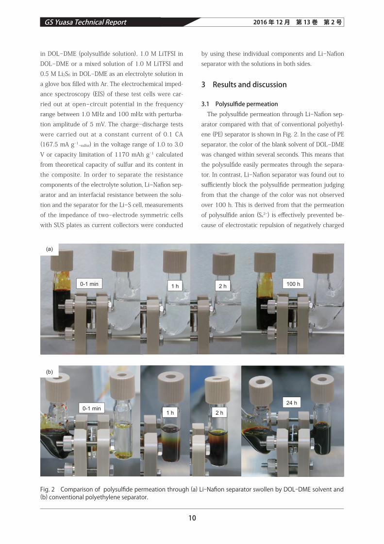
3.1 Polysulfide permeation The polysulfide permeation through Li-Nafion sep-
arator compared with that of conventional polyethyl-ene (PE) separator is shown in Fig. 2. In the case of PE separator, the color of the blank solvent of DOL-DME was changed within several seconds. This means that the polysulfide easily permeates through the separa-tor. In contrast, Li-Nafion separator was found out to sufficiently block the polysulfide permeation judging from that the change of the color was not observed over 100 h. This is derived from that the permeation of polysulfide anion (Sx2-) is effectively prevented be-cause of electrostatic repulsion of negatively charged
Fig. 2 Comparison of polysulfide permeation through (a) Li-Nafion separator swollen by DOL-DME solvent and (b) conventional polyethylene separator.
0-1 min 1 h 2 h 100 h
0-1 min1 h 2 h
24 h
(b)
(a)

11
GS Yuasa Technical Report 2016 年 12 月 第 13巻 第 2号
of the cell with Li-Nafi on separator was maintaining approximately 100% and higher than that of PE sep-arator. Then, the coulombic effi ciency is calculated by 1st charge and 2nd discharge capacity because the charge-discharge tests of the Li-S cell start from dis-charge process. These cycle performances are attrib-uted to the formation of Li2S with poor reversibility during charge-discharge cycle but the migration of polysulfi de anion to the negative electrode was eff ec-tively suppressed only in the case of Li-Nafion sep-arator. In order to suppress the formation of Li2S, a mixed solution of 1.0 M LiTFSI and 0.5 M Li2S6 in DOL-DME is applied to the positive electrode for the cell with Li-Nafion separator. The discharge perfor-mance of the cell was shown in Fig. 5. It was con-fi rmed that the capacity of this cell is extremely lower than that of the cell using 1.0 M LiTFSI in DOL-DME as shown in aforementioned Fig. 3. In order to investi-gate the reason of this low capacity, the EIS measure-ment of the cell was conducted. The result of this measurement was shown in Fig. 6, together with the results of the cells with Li-Nafion separator and PE separator using 1.0 M LiTFSI in DOL-DME. The re-sistance of the cell with Li-Nafi on separator using the mixed solution is found out to be signifi cantly higher than that of the cells with PE or Li-Nafi on separator using 1.0 M LiTFSI in DOL-DME. The high resistance brings a low discharge voltage and the progress of Li2S formation resulting in reaching cut-off voltage of
sulfonated groups in Li-Nafi on membrane4.3.2 Electrochemical performance
The charge-discharge performances and cycle per-formances of Li-S test cells with Li-Nafi on separator and PE separator using 1.0 M LiTFSI in DOL-DME are shown in Fig. 3 and 4, respectively. It turned out that the capacity of the cell with Li-Nafion separator at the fi rst discharge was lower than that of PE separator and the degrees of capacity fading for both cells were almost same level. However, the coulombic effi ciency
Fig. 4 Changes in discharge capacities and coulom-bic efficiencies for the Li-S cells with Li-Nafion sep-arator and PE separator using 1.0 M LiTFSI in DOL-DME at 25℃. The current and cutoff voltage are 0.1 C (167.5 mA g-1-sulfur) and 1.0‒3.0 V, respectively.
Fig. 5 Discharge performance for the Li-S cell with Li-Nafi on separator using the mixed solution of 1.0 M LiTFSI and 0.5 M Li2S6 in DOL-DME at 25℃. The cur-rent and cutoff voltage are 0.1 CA (167.5 mA g-1-sul-fur) and 1.0 V, respectively.
Li-Nafion separator PE separator
Cel
l vol
tage
/ V
Specific capacity / mAh g-1 (-composite)
0.00 200 400 600 800 1000 1200 1400
0.5
1.0
1.5
2.0
2.5
3.0
3.5
Fig. 3 Charge-discharge performances for the Li-S cells with Li-Nafi on separator and PE separator using 1.0 M LiTFSI in DOL-DME at 25℃. The current and cutoff voltage are 0.1 CA (167.5 mA g-1-sulfur) and 1.0‒3.0 V, respectively.
Cycle / -
Cap
acity
/ m
Ah
g-1 (-
com
posi
te)
Cou
lom
bic
effic
ienc
y / %
: Li-Nafion separator
00 2 4 6 8 10
400
800
1200
1600
2000
0
40
20
60
80
100
120: PE separator
Cel
l vol
tage
/ V
Specific capacity / mAh g-1 (-composite)0
0.0
0.5
1.0
1.5
2.0
2.5
3.0
3.5
200 400 600 800 1000 1200 1400
12
GS Yuasa Technical Report 2016 年 12 月 第 13巻 第 2号
Nafi on separator to the highly electrolyte concentrat-ed solution because of decrease of free solvents. Therefore, in the case of polysulfi de solution without LiTFSI, the resistance was lower than that with LiTFSI. Furthermore, we have confirmed that the Li+ ionic conductivity of 0.5 M Li2S6 solution was found out to be 4.4×10⁻⁴ S cm-1 in micro-pored PE separator as same level as that of 1.0 M LiTFSI in DOL-DME (5.4×10⁻⁴ S cm-1). This means that Li2S6 performs as a Li salt instead of LiTFSI in the solution and 0.5 M Li2S6 in DOL-DME without LiTFSI is favorable to the Li-S cell with Li-Nafi on separator.
The result of EIS of the Li-S test cell by using both Li-Nafi on separator and 0.5 M Li2S6 in DOL-DME was shown in Fig. 8. The internal resistance of the cell without LiTFSI showed remarkably lower than that of the cell with LiTFSI. The charge-discharge perfor-mance and the cycle performance of the cell with Li-Nafion separator and the polysulfide solution were shown in Fig. 9 and 10, respectively. The cell was found out to show high capacity corresponding limit-ed value of 1170 mAh g-1 and the high discharge voltage at 1st and 10th discharge. Furthermore, the test cell showed high and stable capacity of 1170 mAh g-1 and high coulombic effi ciency of 100%. The high and stable capacity is considered to be derived from the fact that the polysulfi de solution contributes to electrochemical reaction as the active material, so
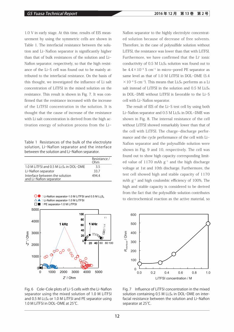
1.0 V in early stage. At this time, results of EIS meas-urement by using the symmetric cells are shown in Table 1. The interfacial resistance between the solu-tion and Li-Nafion separator is significantly higher than that of bulk resistances of the solution and Li-Nafi on separator, respectively, so that the high resist-ance of the Li-S cell was found out to be mainly at-tributed to the interfacial resistance. On the basis of this thought, we investigated the infl uence of Li salt concentration of LiTFSI in the mixed solution on the resistance. This result is shown in Fig. 7. It was con-fi rmed that the resistance increased with the increase of the LiTFSI concentration in the solution. It is thought that the cause of increase of the resistance with Li salt concentration is derived from the high ac-tivation energy of solvation process from the Li-
Fig. 6 Cole-Cole plots of Li-S cells with the Li-Nafi on separator using the mixed solution of 1.0 M LiTFSI and 0.5 M Li2S6 or 1.0 M LiTFSI and PE separator using 1.0 M LiTFSI in DOL-DME at 25℃.
Fig. 7 Infl uence of LiTFSI concentration in the mixed solution containing 0.5 M Li2S6 in DOL-DME on inter-facial resistance between the solution and Li-Nafi on separator at 25℃.
Table 1 Resistances of the bulk of the electrolyte solution, Li-Nafion separator and the interface between the solution and Li-Nafi on separator.
Resistance / Ohm
1.0 M LiTFSI and 0.5 M Li2S6 in DOL-DME 3.5Li-Nafi on separator 33.7Interface between the solutionand Li-Nafi on separator
494.4
:Li-Nafion separator-1.0 M LiTFSI and 0.5 M Li2S6
:Li-Nafion separator-1.0 M LiTFSI:PE separator-1.0 M LiTFSI
0
00
20
40
60
80
100
20 40 60 80 100
0
1000
2000
3000
4000
5000
1000 2000
Z’ / Ohm
-Z’’
/ Ohm
3000 4000 5000
1 kHz1 kHz1 kHz
00
20
40
60
80
100
20 40
1 kHz 1 kHz1 kHz1 kHz
0.00
100
200
300
400
500
600
0.2 0.4 0.6
LiTFSI concentration / M
Rin
terfa
cial /
Ohm
0.8 1.0

13
GS Yuasa Technical Report 2016 年 12 月 第 13巻 第 2号
fectively inhibit the migration of polysulfi de anion to the negative electrode.
4 Conclusion
In this study, we have developed Li-S battery by us-ing both the polysulfi de solution in the positive elec-trode and Li-Nafion separator. The battery with the polysulfi de solution containing LiTFSI shows high in-ternal resistance. The main factor of this high resist-ance is attributed to the interfacial resistance between the solution and the Li-Nafi on separator. And it found out that the resistance is strongly aff ected by the Li salt concentration in the solution and the polysulfi de solution without LiTFSI shows the lowest value of the resistance. The battery using the polysulfi de solution without LiTFSI successfully achieved to show high and stable capacity of 1170 mAh g-1 based on the mass of the positive composite material and high cou-lombic efficiency of approximately 100%. These are attributed to the facts that the formation of Li2S and the polysulfide shuttle are effectively suppressed by using the polysulfide solution and Li-Nafion separa-tor, respectively.
that only if the capacity is limited at the calculated value from theoretical capacity of sulfur in the SPC, the formation of Li2S is suppressed because the utili-zation of sulfur decreases, judging from that the volt-age at the end of discharge doesnʼ t reach the level for the formation of Li2S at not only 1st but also 10th discharge curve as shown in Fig. 9. The high coulom-bic effi ciency is attributed to that the polysulfi de shut-tle is suppressed because Li-Nafi on separator can ef-
Fig. 9 Charge-discharge performances at 1st and 10th cycles for the Li-S cell with Li-Nafi on separator using 0.5 M Li2S6 in DOL-DME at 25℃. The current is 0.1 CA (167.5 mA g-1-sulfur). The value of capacity limitation is 1170 mAh g-1 calculated from theoretical capacity of sulfur and its content in SPC.
Fig. 10 Changes in discharge capacity and coulom-bic effi ciency for the Li-S cells with Li-Nafi on separa-tor using 0.5 M Li2S6 in DOL-DME at 25℃. The current is 0.1 CA (167.5 mA g-1-sulfur). The value of capacity limitation is 1170 mAh g-1 calculated from theoretical capacity of sulfur and its content in SPC.
Fig. 8 Cole-Cole plots of the Li-S cells with Li-Nafi on separator using 0.5 M Li2S6 or the mixed solution of 1.0 M LiTFSI and 0.5 M Li2S6 in DOL-DME at 25℃.
: 0.5 M Li2S6 in DOL-DME: 1.0 M LiTFSI and 0.5 M Li2S6 in DOL-DME
1 kHz
00
1000
2000
3000
4000
50001000
800
600
400
200
00 200 400 600 800 1000
1000 2000 3000
Z’ / Ohm
-Z’’ /
Ohm
4000 5000
1 kHz
1 kHz
1000
800
600
400
200
00 200 400 600 800 1000
1 kHz
Cel
l vol
tage
/ V
Specific capacity / mAh g-1 (-composite)0
0.0
0.5
1.0
1.5
2.0
2.5
3.0
3.5
200 400 600 800 1000 1200 1400
1st 10th
Cycle / -0
0
400
800
1200
1600
2000
2400
0
20
40
60
80
100
120
2 4 6 8 10
Cap
acity
/ m
Ah
g-1 (-
com
posi
te)
Cou
lom
bic
effic
ienc
y / %

14
GS Yuasa Technical Report 2016 年 12 月 第 13巻 第 2号
3. Jie. Gao, Michael A. Lowe, Yasuyuki Kiya and Hector D. Abruna, Journal of Physical Chemistry C , 115, 25132 (2011).
4. Zhaoqing Jin, Kai Xie, Xiaobin Hong, Zongqian Hu and Xiang Liu, Journal of Power Sources , 218, 163 (2012).
5. Hironori Orikasa and Takahiro Morishita, TANSO , 254, 153 (2012).
References
1. Heisuke Nishikawa, Shuji Hitomi and Hiroaki Yoshida, GS Yuasa Technical Report , 12 (1), 9 (2015).
2. Shuru Chen, Fang Dai, Mikhail L. Gordin and Donghai Wang, The Royal Society of Chemistry , 3, 3540 (2013).