Development of Interface and Diagnostic System for...
3
─────────────── * [email protected] DEVELOPMENT OF AN INTERFACE AND DIAGNOSTIC SYSTEM FOR THE ECR ION SOURCE AT KBSI Jungbae Bahng, Eun-San Kim, Kyungpook National University, Daegu 702-701, Korea Byoung Seob Lee*, Jung-Woo Ok , Seyong Choi, Jonggi Hong, Seong Jun Kim, Jin Yong Park, Chang Seouk Shin, Jang-Hee Yoon, Mi-Sook Won, Korea Basic Science Institute, Busan, 609-735, Korea Abstract A 28 GHz superconducting ECR (electron cyclotron resonance) ion source was recently developed at KBSI (Korea Basic Science Institute) to produce a high current and high charge state ions [1]. The condition of the ion beam extracted from the ion source should be analyzed by a diagnosis tool after accelerating and focusing process. For this, we developed an ion beam diagnostic system composed of a slit, a wire scanner, a view screen and a faraday cup. The interface of the diagnostic system was designed so as to achieve stable operation of the ECR ion source. The information obtained from the diagnostic system can be used as a reference in studies of the optimum beam conditions needed to adjust the extraction parameters. The details of the diagnostic system and initial test results will be reported. INTRODUCTION A heavy ion accelerator using fast neutrons was developed for the radiography facility at KBSI. A 28 GHz superconducting ECR (electron cyclotron resonance) ion source was employed for a high current ion beam to meet the requirements needed for generating fast neutrons. The key part of heavy ion accelerator system is comprised of the 28 GHz ECR ion source, an LEBT (low energy beam transport) system with a series of electromagnets (a dipole, two quadrupoles and three solenoids), RFQ (radio frequency quadrupole) for ion beam acceleration from 12 keV/u to 500 keV/u and DTL (Drift Tube linear accelerator) for acceleration up to 2.7 MeV/u. The layout is shown in figure 1. Neutron imaging is planned to be generated by the reaction of an accelerated lithium beam and a hydrogen target. The figure 2 shows the components of the LEBT system, which are a dipole magnet, three solenoids, two quadrupoles and the diagnostic system. Ion beams extracted from the ECR ion source are transported to the RFQ entrance via the LEBT system. After analysing the process at the dipole magnet, we prepared a diagnostic chamber to obtain the beam profile, the transverse emittance and the intensity of the beam current at this location. Inside of the diagnostic chamber, we installed horizontal and vertical slits, a wire scanner, the screen monitor and the faraday-cup. The slits and wire scanner permit us to select the desired beam and to measure the transverse emittance. The screen monitor and wire scanner are utilized to identify the horizontal and vertical profiles of the ion beam. The faraday-cup provides information regarding the beam intensity as an electrical current. Figure 1: The layout of the KBSI accelerator. Pair Solenoid Magnets Dipole Magnet Quadrupole Magnet (Spare) Beam Diagnostic System Quadrupole Magnets Pair Solenoid Magnet Beam Diagnostic System (Spare) Figure 2: Schematic diagram of the LEBT system. Simulations of the ion beam optics were carried out using the TRANSPORT code. The basic parameters used in this simulation are listed in Table 1. Proceedings of ECRIS-2014, Nizhny Novgorod, Russia MOPPH011 Status reports and new developments ISBN 978-3-95450-158-8 61 Copyright © 2014 CC-BY-3.0 and by the respective authors
-
Upload
nguyennguyet -
Category
Documents
-
view
214 -
download
0
Transcript of Development of Interface and Diagnostic System for...

─────────────── * [email protected]
DEVELOPMENT OF AN INTERFACE AND DIAGNOSTIC SYSTEM FOR THE ECR ION SOURCE AT KBSI
Jungbae Bahng, Eun-San Kim, Kyungpook National University, Daegu 702-701, Korea
Byoung Seob Lee*, Jung-Woo Ok , Seyong Choi, Jonggi Hong, Seong Jun Kim, Jin Yong Park, Chang Seouk Shin, Jang-Hee Yoon, Mi-Sook Won, Korea Basic Science Institute,
Busan, 609-735, Korea
Abstract A 28 GHz superconducting ECR (electron cyclotron
resonance) ion source was recently developed at KBSI (Korea Basic Science Institute) to produce a high current and high charge state ions [1]. The condition of the ion beam extracted from the ion source should be analyzed by a diagnosis tool after accelerating and focusing process. For this, we developed an ion beam diagnostic system composed of a slit, a wire scanner, a view screen and a faraday cup. The interface of the diagnostic system was designed so as to achieve stable operation of the ECR ion source. The information obtained from the diagnostic system can be used as a reference in studies of the optimum beam conditions needed to adjust the extraction parameters. The details of the diagnostic system and initial test results will be reported.
INTRODUCTION A heavy ion accelerator using fast neutrons was
developed for the radiography facility at KBSI. A 28 GHz superconducting ECR (electron cyclotron resonance) ion source was employed for a high current ion beam to meet the requirements needed for generating fast neutrons. The key part of heavy ion accelerator system is comprised of the 28 GHz ECR ion source, an LEBT (low energy beam transport) system with a series of electromagnets (a dipole, two quadrupoles and three solenoids), RFQ (radio frequency quadrupole) for ion beam acceleration from 12 keV/u to 500 keV/u and DTL (Drift Tube linear accelerator) for acceleration up to 2.7 MeV/u. The layout is shown in figure 1. Neutron imaging is planned to be generated by the reaction of an accelerated lithium beam and a hydrogen target. The figure 2 shows the components of the LEBT system,
which are a dipole magnet, three solenoids, two quadrupoles and the diagnostic system. Ion beams extracted from the ECR ion source are transported to the RFQ entrance via the LEBT system. After analysing the process at the dipole magnet, we prepared a diagnostic chamber to obtain the beam profile, the transverse emittance and the intensity of the beam current at this location. Inside of the diagnostic chamber, we installed
horizontal and vertical slits, a wire scanner, the screen monitor and the faraday-cup. The slits and wire scanner permit us to select the desired beam and to measure the transverse emittance. The screen monitor and wire scanner are utilized to identify the horizontal and vertical profiles of the ion beam. The faraday-cup provides information regarding the beam intensity as an electrical current.
Figure 1: The layout of the KBSI accelerator.
Pair Solenoid Magnets
Dipole Magnet
QuadrupoleMagnet(Spare)
BeamDiagnostic
System
Quadrupole Magnets Pair Solenoid Magnet
Beam Diagnostic System(Spare)
Figure 2: Schematic diagram of the LEBT system.
Simulations of the ion beam optics were carried out
using the TRANSPORT code. The basic parameters used in this simulation are listed in Table 1.
Proceedings of ECRIS-2014, Nizhny Novgorod, Russia MOPPH011
Status reports and new developmentsISBN 978-3-95450-158-8
61 Copy
right
©20
14CC
-BY-
3.0
and
byth
eres
pect
ivea
utho
rs
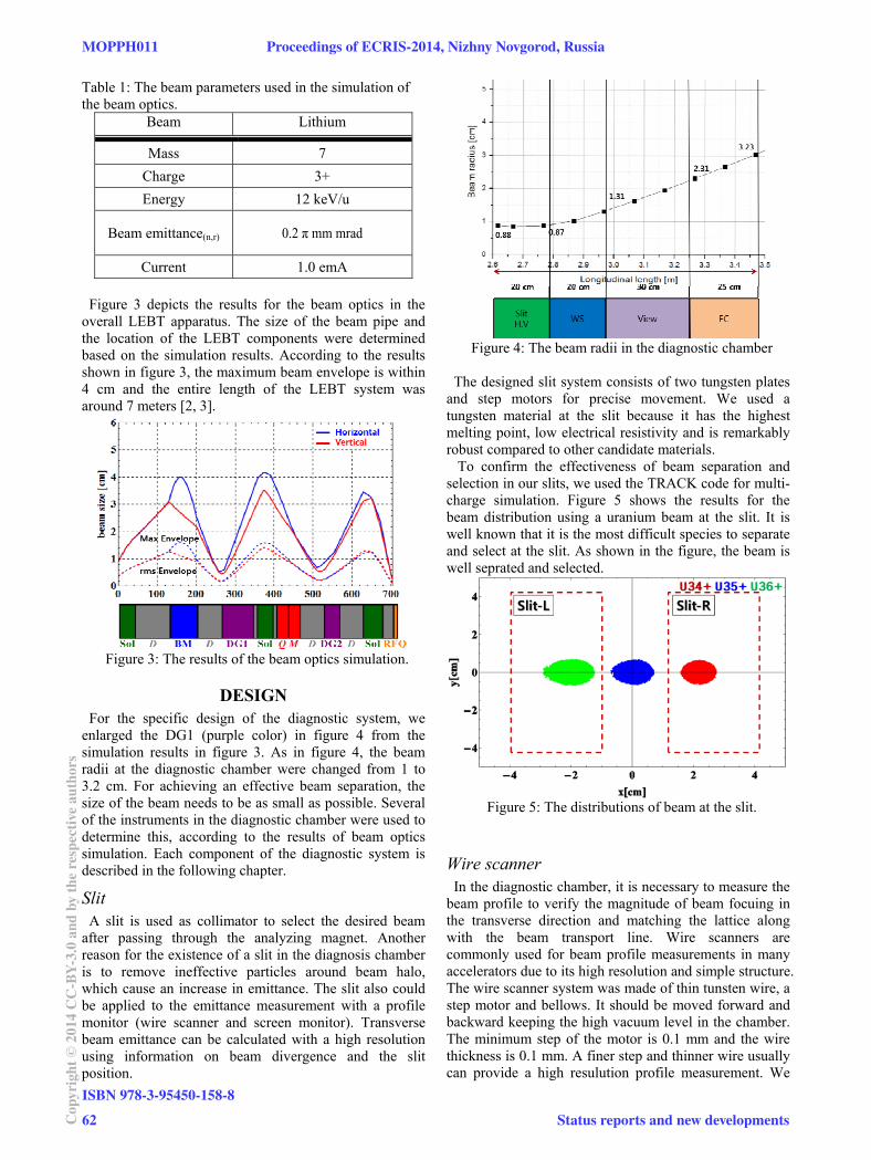
Table 1: The beam parameters used in the simulation of the beam optics.
Beam Lithium
Mass 7 Charge 3+ Energy 12 keV/u
Beam emittance(n,r) 0.2 π mm mrad
Current 1.0 emA Figure 3 depicts the results for the beam optics in the
overall LEBT apparatus. The size of the beam pipe and the location of the LEBT components were determined based on the simulation results. According to the results shown in figure 3, the maximum beam envelope is within 4 cm and the entire length of the LEBT system was around 7 meters [2, 3].
Figure 3: The results of the beam optics simulation.
DESIGN For the specific design of the diagnostic system, we
enlarged the DG1 (purple color) in figure 4 from the simulation results in figure 3. As in figure 4, the beam radii at the diagnostic chamber were changed from 1 to 3.2 cm. For achieving an effective beam separation, the size of the beam needs to be as small as possible. Several of the instruments in the diagnostic chamber were used to determine this, according to the results of beam optics simulation. Each component of the diagnostic system is described in the following chapter.
Slit A slit is used as collimator to select the desired beam
after passing through the analyzing magnet. Another reason for the existence of a slit in the diagnosis chamber is to remove ineffective particles around beam halo, which cause an increase in emittance. The slit also could be applied to the emittance measurement with a profile monitor (wire scanner and screen monitor). Transverse beam emittance can be calculated with a high resolution using information on beam divergence and the slit position.
Figure 4: The beam radii in the diagnostic chamber
The designed slit system consists of two tungsten plates
and step motors for precise movement. We used a tungsten material at the slit because it has the highest melting point, low electrical resistivity and is remarkably robust compared to other candidate materials. To confirm the effectiveness of beam separation and selection in our slits, we used the TRACK code for multi-charge simulation. Figure 5 shows the results for the beam distribution using a uranium beam at the slit. It is well known that it is the most difficult species to separate and select at the slit. As shown in the figure, the beam is well seprated and selected.
Figure 5: The distributions of beam at the slit.
Wire scanner In the diagnostic chamber, it is necessary to measure the
beam profile to verify the magnitude of beam focuing in the transverse direction and matching the lattice along with the beam transport line. Wire scanners are commonly used for beam profile measurements in many accelerators due to its high resolution and simple structure. The wire scanner system was made of thin tunsten wire, a step motor and bellows. It should be moved forward and backward keeping the high vacuum level in the chamber. The minimum step of the motor is 0.1 mm and the wire thickness is 0.1 mm. A finer step and thinner wire usually can provide a high resulution profile measurement. We
MOPPH011 Proceedings of ECRIS-2014, Nizhny Novgorod, Russia
ISBN 978-3-95450-158-862Co
pyrig
ht©
2014
CC-B
Y-3.
0an
dby
ther
espe
ctiv
eaut
hors
Status reports and new developments

adopted three wires in wire scanner. The advantage of a three wire scanner is that not only can the projection signal be obtained as in a conventional two wires scanner but additional information such as the correlation, the twiss alpha can be obtained in a single measurement.
Screen monitor The screens, which are made of stainless steel, are thought to be a kind of popular profile monitor due to its simplicity and convenience of use. The screen monitor system consists of a stainless steel screen, a CCD camera and an air cylinder for achieving movement. The screen was tilted at a 45° angle so as to permit the beam to be viewed through a viewport. The thickness of the screen was 10 mm with several pin holes to calibrate the physical position. We coated the the surface layer of the screen with Y2O2S. Such a doping material provides the optimized conditions for achieving a short decay time and a high luminance, even at low energy.
Faraday Cup A Faraday Cup is typically used to measure the intensity
of the beam current. Furthermore the faraday cup is also used as a dump to consume the beam energy. During the dumping process, heat is generated in the device. We therefore added a cooling water channel to control the temperature in the structure. The interaction of the beam and faraday cup produces a secondary electron emission (SEE) effect. To avoid secondary particles outflowing to another device, we adopted a high voltage plate to suppress the SEE effect. The Faraday cup consists of a copper body, an electrode
for high voltage, a water cooling channel and an air cylinder for the movement in the chamber. Figure 6 shows the structure of the faraday cup. The copper body is 55 mm in diameter and 220 mm in length. The faraday cup will be operated at an electrical potential at -200 V at the electrode to suppress outflowing SEE. The faraday cup was designed to be cooled with the cooling water with a flow rate of 0.5 m/s, which enables to to operate the equipment at room tempeature.
Figure 6: The structure of faraday cup.
CONCLUSIONS The size and position of a diagnostic system was
determined by a simulation of the beam optics of teh equipment. The components of the diagnostic system include a slit, a screen monitor, a wire scanner and a faraday cup. They were successfully installed inside the diagnostic chamber, as shown in figure 7. The diagnostic system is used to obtain information regarding the ion beam, such as beam profile, beam intensity and beam emittance. An initial test of most of the components in the diagnostic system was performed to check the movement and the communication between devices and controller. Beam extraction from a 28 GHz superconducting ECR ion source is scheduled the autumn in 2014. We expect that the developed diagnostic system will be ready to use at the time of the KBSI ion beam commissioning.
Figure 7: The installed diagnostic system.
REFERENCES [1] M. Won, et. al., International Nuclear Information
System Vol.44 IS.09 44026105, 2012. [2] J. Bahng, et. al., “Design study of LEBT beam line in
KBSI at Busan”, Journal of Korea Physics Society, 2011.
[3] J. Bahng, et. al., “Design study of LEBT beam line and Diagnostics for ECR-IS in KBSI”, Journal of Korea Physics Society, 2012.
Proceedings of ECRIS-2014, Nizhny Novgorod, Russia MOPPH011
Status reports and new developmentsISBN 978-3-95450-158-8
63 Copy
right
©20
14CC
-BY-
3.0
and
byth
eres
pect
ivea
utho
rs