Development of Design Standards for Low-Volume …€¦ · · 2016-08-02Development of Design...
45
Development of Design Standards for Low-Volume Roads in Ethiopia AFCAP/ETH/005/A Otta Seal Demonstration project: Combel Village, Tulubolo-Kela Road Construction and Workshop Report Report No. CPR1614 C Overby (Consultant) A Otto May 2013
Transcript of Development of Design Standards for Low-Volume …€¦ · · 2016-08-02Development of Design...

Development of Design Standards for Low-Volume Roads in Ethiopia
AFCAP/ETH/005/A
Otta Seal Demonstration project: Combel Village, Tulubolo-Kela Road Construction and Workshop Report
Report No. CPR1614
C Overby (Consultant) A Otto
May 2013

This project was funded by the Africa Community Access Programme (AFCAP) which promotes safe and sustainable access to markets, healthcare, education, employment and social and political networks for rural communities in Africa. Launched in June 2008 and managed by Crown Agents, the five year-long, UK government (DFID) funded project, supports research and knowledge sharing between participating countries to enhance the uptake of low cost, proven solutions for rural access that maximise the use of local resources. The programme is currently active in Ethiopia, Kenya, Ghana, Malawi, Mozambique, Tanzania, Zambia, South Africa, Democratic Republic of Congo and South Sudan and is developing relationships with a number of other countries and regional organisations across Africa. This material has been funded by UKaid from the Department for International Development, however the views expressed do not necessarily reflect the department’s or the managing agent’s official policies. For further information visit https://www.afcap.org

List of Tables ....................................................................................................................................... 3
List of Figures ...................................................................................................................................... 3
1 Background ..................................................................................................................................... 1
1.1 Project objectives. ................................................................................................................... 1
2 Site Location .................................................................................................................................... 1
2.1 Topography and cross section ................................................................................................ 2
3 Pavement Design ............................................................................................................................ 2
3.1 Existing road and materials ........................................................................................................... 2
3.1 Pavement design for Otta seal ................................................................................................ 3
3.2 Construction of the pavement layers ..................................................................................... 4
3.3 Primed base layer.................................................................................................................... 4
3.4 Layout of the demonstration project ...................................................................................... 5
3.5 Properties of the aggregate .................................................................................................... 5
4 Surfacing aggregate ........................................................................................................................ 5
4.1 Crushed rock aggregate .......................................................................................................... 6
4.2 Crusher dust ............................................................................................................................ 6
4.3 Weathered basalt.................................................................................................................... 7
4.4 Volcanic Cinder aggregate ...................................................................................................... 8
5 CONSTRUCTION OF THE OTTA SEAL / SAND SEAL .......................................................................... 8
5.1 Introduction ............................................................................................................................ 8
5.2 Type of binder and spraying ................................................................................................... 9
5.3 Aggregate application ........................................................................................................... 11
5.4 Weather condition during construction ............................................................................... 13
6 CONSTRUCTION CONSTRAINTS..................................................................................................... 13
6.1 General .................................................................................................................................. 13
6.1.1 Bitumen distributor. ...................................................................................................... 13
6.1.2 Aggregate. ..................................................................................................................... 13
6.1.3 Sealing operations. ........................................................................................................ 14
7 CONSIDERATIONS FOR APPLICATION OF THE SECOND SEAL........................................................ 14
8 WORKSHOP AND FIELD VISIT ........................................................................................................ 14
8.1 Introduction .......................................................................................................................... 14
8.2 Purpose and Scope ................................................................................................................ 14
8.3 Field visit ............................................................................................................................... 15
9 Provisional cost estimates for Combel .......................................................................................... 15
9.1 Distortion of costs ................................................................................................................. 15
9.2 Estimated costs ..................................................................................................................... 16
9.3 Discussion of cost estimates ................................................................................................. 18
9.4 Final remarks on costs .......................................................................................................... 18

10 Prevailing problems with mainstreaming Otta seal technology. .............................................. 19
Appendix A ............................................................................................................................................ 20
Layout of test sections .......................................................................................................................... 20
Appendix B ............................................................................................................................................ 22
Workshop Presentations....................................................................................................................... 22
List of Tables
Table 3.1 Pavement Design Parameters ................................................................................................. 3 Table 3.2 Base compaction Base Compaction ........................................................................................ 4 Table 5.1 Binder spray rates for the sand seal section 0 – 100 m, including transition zone. ............... 9 Table 5.2 Actual binder spray rates for the section 100m to 300m using screened volcanic cinder aggregate .............................................................................................................................................. 10 Table 5.3 Actual spray rates for the section 300m to 600m using screened weathered basalt .......... 10 Table 5.4 Actual binder spray rates for the section 600m to 1900m and 34m transition zone using crushed basalt ....................................................................................................................................... 10
List of Figures
Figure 1 Location of the project area ...................................................................................................... 2 Figure 2 Coarse base and dense base layers after priming .................................................................... 5 Figure 3recommended aggregate properties for an Otta seal ............................................................... 6 Figure 4 Grading curve from Awash quarry after mixing including other key properties ...................... 6 Figure 5 Grading curve of crusher dust from Awash quarry. .................................................................. 7 Figure 6 Grading curve for natural gravel of weathered basalt (screened) including other key properties ................................................................................................................................................ 7 Figure 7 Grading curve for volcanic cinder gravel (screened) including other key properties ............... 8 Figure 8 Checking the spray bar nozzles prior to spraying of binder ...................................................... 9 Figure 9 Paper laid to achieve straight transverse joints ...................................................................... 11 Figure 10 The front-end loader “airing” the aggregate in order to remove dust ................................. 12 Figure 11 Self-propelled chipspreader in operation and the sprading of aggregate by the use of labour. ................................................................................................................................................... 12 Figure 12 Rolling in progress by the use of both a pneumatic roller and the loaded tipper truck....... 13

1 | P a g e
1 Background
The Ethiopian Road Authority (ERA) has included demonstration projects on the use of Otta seal surfacing under the Africa Community Access Programme (AFCAP). This type of seal is an alternative to the more commonly used chip seal and other more conventional surface treatments. The main project objectives in Ethiopia were to demonstrate Otta seal technology and to research the use of locally available materials. Two sections of the road network were identified for inclusion in the demonstration project. One section 1900 metres in length was located at Combel village along the Tulubulo – Kela road and the other section 3000 metres long was located in the village of Gerado on the Combolcha – Mekaneselam road. This report deals with the construction of the section at Combel.
1.1 Project objectives
The demonstration project had three objectives:
1. Demonstrate an Otta seal using aggregate that is within the prescribed grading and strength
requirements
2. Demonstrate the use of locally available natural gravel (decomposed weathered basalt and
volcanic cinder aggregate) that might perform satisfactorily although outside the specified
aggregate requirements.
3. Demonstrate that waste fines from crushing (crusher dust) could be used as a sand seal.
2 Site Location
The Tulubola – Kela road through the Combel village is situated south of Addis Ababa, 37 km from Tulubolo – along the Tulubolo – Kela road. One of the reasons for this location was that it was relatively close to the capital Addis Ababa and that the sources of aggregate used were relatively close to the project site. Bitumen was hauled from the Tiya heating plant, 69 km along Alemegena – Butajira road. Figure 1 shows the location of the demonstration project. The village location was selected in order to demonstrate the potential benefits of using the technique to improve rural roads including roads through rural residential areas. The benefits of sealing these roads include improved all-weather access to facilities within the village as well as the significant environmental benefits from reduced dust pollution compared with the existing gravel road.

2 | P a g e
Figure 1 Location of the project area
2.1 Topography and cross section
The demonstration section itself is 1900 m in length. Transition zones of 75 metres at the start of the section and 34 metres at the end were also constructed. The first 200 metres are located on relatively flat terrain. The following 900 metres includes an uphill gradient of between 3% and 5% in the direction towards the village with a relatively flat section through Combel village itself up to the end of the trial. The road width varied between 5.00 and 7.00 metres. The maximum sealed road width was 6.30 metres. The side drainage has been adequately improved throughout the entire section.
3 Pavement Design
The pavement was designed on the basis of the ERA’s “Design Standards for Low Volume: Part B 2011”.
3.1 Existing road and materials
A simple classified traffic count was carried out. The design traffic estimated over a period of 15 years is shown in Table 3.1 in which a summary of laboratory and field results are also given. A key note from the table is the fact that the design chart requires a G65 base layer on top of a G30 sub-base layer each of 125mm thickness. It was not possible to find natural gravel within the project
Site/ Combel
Addis
Bitumen / Tiya
Cinder
Quarry/ Awash

3 | P a g e
site that met the materials strength and plasticity requirements in the design charts. The choice of materials was moving a crusher near the site so that the harder ‘fresh’ basalt could be used a s base course,, hauling crushed stone base from an established source more than 130km away, or using the available weathered basalt. Field tests using the Dynamic Cone Penetrometer (DCP) on the existing wearing course showed that the lowest in-situ CBR was 120% and the average thickness of gravel was 170mm. The soaked CBR of the weathered basalt proposed for use as base course was only 45% but its strength at optimum moisture content (OMC) and specified density was 65%.
3.1 Pavement design for Otta seal
Based on the measurements taken on the existing road, it was considered appropriate to construct a 200mm layer of weathered basalt base course on top of the existing wearing course, which would act as a sub-base and met the strength requirements for sub-base materials in the design chart. Table 3.1 Pavement Design Parameters
Pavement Design Parameters
Commercial Vehicles (ADT) Two-way ADT Estimated
ESA/vehicle ESA/day
Large Bus 24 1.0 24.0
Medium Trucks 8 2.5 20.0
Heavy Trucks 4 5.0 20.0
Sum 64.0
ESAs/Day in one direction 32.0
Design MESA (15 yrs, 5% growth) 0.04
Design Class LV 2
Laboratory Results Others
Subgrade CBR (4-day soaked, Mod AASHTO) 15 S5 PI = 22
Existing Gravel Wearing Course CBR (%) 44 G45 PI = 23
Proposed Base Material CBR (%) 45*; 65** G45 PI = 20
Proposed Base Material MDD = 2.26g/cm3 OMC = 8%
*soaked at OMC **at OMC
Field Tests
Existing Layer CBR (%) Thickness
(mm) Class
Gravel Wearing Course CBR 120 170 G80
Design Chart Requirement (S5, LV2) Thickness (mm) Strength Class Others
Base Layer 125 G65
PI<15, PM<400,
Grading "B"
Sub-base Layer 125 G30
There is clearly a risk involved in using weathered basalt materials due to their susceptibility to damage from moisture ingress but the costs of extracting and hauling conventional materials that fully met the specifications for base course were prohibitive. The perceived risks were reduced by the decision to use a double seal and to seal the carriageway right up to the side drains. It is expected that this will reduce the possibility of the ingress of moisture and of any subsequent deleterious effects to the performance of the basalt base and sub-base. On areas of flat geometry

4 | P a g e
where there is a possibility of ponding of storm water, it is proposed that the side drains should be lined.
3.2 Construction of the pavement layers
In the latest ERA Design Manual, the recommended standard for roads in villages is that the carriageway should be 9.3m wide. The existing carriageway was 5.5m wide but at this location, there were various constraining influences which limited widening of the carriageway and ERA recommended a maximum design paved width of 6.3m which was used throughout the trial section. During construction, the existing road was widened to a nominal width of 7metres by a benching technique with material from the borrow pit used for construction of the base. The edge of the road was then trimmed on both left and right hand sides to form the side drains. The existing carriageway was then scarified to 150mm depth and re-compacted. The weathered basalt base material was imported from borrow pit, which was located 7km from the site, spread 250mm thick on the finished sub-base to 2.5% camber and compacted to a thickness of approximately 200mm. The material before compaction had a significant quantity of oversize material which broke down upon compaction. The rainy season began in July 2012, before construction of the base was completed, and work was suspended. The rains continued for a period of more than 3months. The major detrimental effect of the rains was soaking of the base course and washing out the fines from the base material. When construction resumed, it was clear that considerable damage to the base had occurred. The base was scarified, patched and extra material added where required. Fine material was added under vibration compaction. The remedial works took place in January 2013. Further re-compaction was also required on some sections following the remedial work on the base. As a consequence of the rains and the re-working of the base, some smoothness and tightness of the base was lost. This necessitated some sections of the carriageway being re-cut and the final road width varied between 5m and 7m. The final base compaction densities before sealing are shown in the Table 3.2. Table 3.2 Base compaction Base Compaction
Chainage Test Location Relative compaction (% of MDD)
39.125 CL 99
38.950 LHS 100
38.775 RHS 95
38.6 CL 100
38.425 LHS 95
38.25 RHS 100
38.075 CL 99
37.9 LHS 96
37.725 RHS 97
37.55 CL 99
37.375 LHS 98
3.3 Primed base layer
The gravel road base layer of weathered basalt road base was primed with MC 30 at an application rate of +/- 1.0 l/m2 about a week before the sealing operation started.

5 | P a g e
The primed base was in a general satisfactory condition but segregation in the base material in localised areas left the base rather open in general from chainage 0 to 600 metres. The binder application rates for the surfacing were slightly increased in these areas to allow for this. From chainage 600 – 1000 metres, the base was very dense and hard. At the end of the section chainage 1000 – 1900 metres the base had become somewhat loose and areas with lamination and had to be improved prior to sealing. Figure 2 shows two photographs of the primed base. Figure 2 Coarse base and dense base layers after priming
3.4 Layout of the demonstration project
The demonstration project comprises of four sections of various length using the following different types of aggregate and bitumen viscosity. All sections will eventually have a double seal, which will be applied 3 months after completion of the first seal. This is to ensure that all the volatile oils (solvent) have evaporated prior to the second seal being applied. If the volatile oils trapped are between the two seals, then the result will be heavy bleeding and instability of the seal. The layout of the demonstration project through Combel village is shown in Appendix A.
3.5 Properties of the aggregate
The demonstration project used four types of aggregate:
Plant crushed from Awash quarry “hard” fresh rock basalt.
Crusher dust < 5.0 mm from Awash quarry.
Decomposed basalt labour screened from project road.
Volcanic cinder gravel screened by labour to produce the required grading.
4 Surfacing aggregate
The recommended grading limits and other commonly-used key aggregate properties for an Otta
seal are shown in Figure 3.

6 | P a g e
Figure 3recommended aggregate properties for an Otta seal
4.1 Crushed rock aggregate
The aggregate produced from crushed rock was obtained from the quarry at Awash. The parent rock was “hard” fresh rock basalt. Three size fractions (¾”, 3/8” and < 5.0 mm) were produced at the quarry, hauled to site and mixed at site in the proportions of 2 + 2 + 1, respectively, to produce the required grading. The resulting grading and other key properties are shown in figure 4. Figure 4 Grading curve from Awash quarry after mixing including other key properties
The grading of the above material follows the “medium” grading in the Otta seal Design Guide, although the material is somewhat gap-graded because the fraction between 6,7mm and 4mm is missing. The other key properties are well within the requirements such (e.g. PI of 9, Flakiness of 15, 10% FACT dry as high as 300kN and a wet/dry value of 0.87. Water absoption is low at 1,0%.
4.2 Crusher dust
The crusher dust is the fine fraction (< 5mm) produced at the crusher. It is alaso often referred to as crusher –waste. The grading curve for the crusher dust is shown in Figure .
7 | P a g e
Figure 5 Grading curve of crusher dust from Awash quarry.
4.3 Weathered basalt
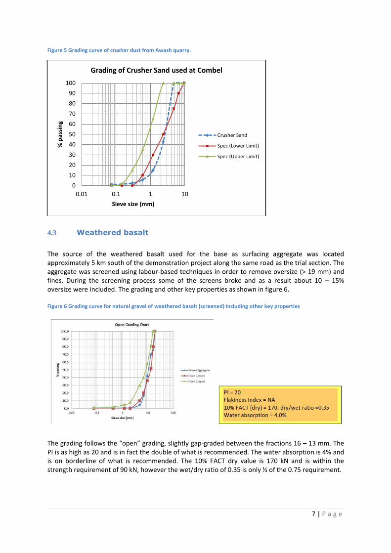
The source of the weathered basalt used for the base as surfacing aggregate was located approximately 5 km south of the demonstration project along the same road as the trial section. The aggregate was screened using labour-based techniques in order to remove oversize (> 19 mm) and fines. During the screening process some of the screens broke and as a result about 10 – 15% oversize were included. The grading and other key properties as shown in figure 6. Figure 6 Grading curve for natural gravel of weathered basalt (screened) including other key properties
The grading follows the “open” grading, slightly gap-graded between the fractions 16 – 13 mm. The PI is as high as 20 and is in fact the double of what is recommended. The water absorption is 4% and is on borderline of what is recommended. The 10% FACT dry value is 170 kN and is within the strength requirement of 90 kN, however the wet/dry ratio of 0.35 is only ½ of the 0.75 requirement.
0
10
20
30
40
50
60
70
80
90
100
0.01 0.1 1 10
% p
assi
ng
Sieve size (mm)
Grading of Crusher Sand used at Combel
Crusher Sand
Spec (Lower Limit)
Spec (Upper Limit)

8 | P a g e
4.4 Volcanic Cinder aggregate
Volcanic Cinder aggregate is abundant in the project area and in other places within the country. The aggregate can easily be extracted and screened by labour to remove oversize and fines from the bulk sample. The source was about 46 km west of the demonstration project. Figure 7 shows the grading and other key properties for the cinder aggregate. Figure 7 Grading curve for volcanic cinder gravel (screened) including other key properties
The grading follows the “dense” grading down to about the 2 mm sieve, then follows a much finer grading (about 10 %) than the recommended Otta seal grading requirements. The fraction passing the 0.075 mm sieve is 22%, which is more than double than the recommended value. The other key properties such as a PI of 13 is higher than the recommended value (10). The 10% FACT dry is as low as 39 (requirement 90) but the wet/dry ratio is 0.85. The most challenging parameter is the high water absorption value of 13%.
5 CONSTRUCTION OF THE OTTA SEAL / SAND SEAL
5.1 Introduction
The sealing work was carried out by an ERA Emergency Works Unit, using the following equipment:
Bitumen distributor (6000 l capacity).
Self-proppelled chip-spreader.
2 tipper trucks (capacity 9 m3)
Pneumatic roller (12 tons)
Steel roller (8 tons)
Front-end loader.
Wheel barrows, brooms and shovels incl. an adequate number of labours.
The primed base was protected by a diversion and watchmen patrolled the primed area in order to keep livestock, the hooves of which picked up the bitumen-based prime leaving ‘dimples’ of unpromed base material. The aggregate to be used were stockpiled on site adjacent to the road. The sealing operation took place between the 30th of January and 8th of February 2013.

9 | P a g e
5.2 Type of binder and spraying
Two types of binders were used. The base binder bitumen was MC 3000 and a quantity was cut back to MC 800 viscosity by adding 15% by volume of MC 30 used for priming. Cutting-back was carried out on site. The bitumen hot spray rates ranged from 1.1 -3.9 l/m2. The binder application rates were initially increased from the original design values by 0.1 – 0.2 l/m2
due to the coaresness of the base and the amount of fines in the aggregate which appeared to be significantly different from the results obtained in the laboratory. The bitumen distributor did not have a dip stick to measure the volume in the disributor tank which is normally used as a check on volume delivered and hence the spray rate. Consequently the spray rate was controlled using a low speed gauge on the dashboard. This made it very difficult for the driver to maintain an accurate speed whilst at the same time ensuring that the vehicle followed the required spray line. Hence, the actual spray rates produced were rather erratic and adjustments had to be made on a regular basis as the rate of spray was checked after each run using trays placed on the road prior to spraying the binder. The laboratory personel weighed the trays and calculated the actual binder spray rate applied by the distributor. Prior to the daily sealing operations. the nozzels of the bitumen distributer where checked on site as shown in Figure 8. Figure 8 Checking the spray bar nozzles prior to spraying of binder
The actual binder spray rates for each “spray pull” for each sub-section of the trial is given for the sand seal, cinder gravel, weathered bassalt, in Table 5.1, Table 5.2, Table 5.3 and Table 5.4 respecitively and for both the right hand side (RHS) and left hand side (LHS) of the road. Table 5.1 Binder spray rates for the sand seal section 0 – 100 m, including transition zone.
RHS Chainage (m)
Type of seal Binder used
Bitumen distributor
Speed
Actual spray rate (kg/m2)
Comments
Minus 0 - 74 Sand seal
(crusher dust)
MC 3000
0.8 0.90 Transistion zone. Crusher dust applied by labours
0 – 40 1.15 1.69 Crusher dust applied by labour 40 – 100 0,.9 1.47
LHS Chainage
(m)

10 | P a g e
Minus 0 - 74 Sand seal
(crusher dust)
MC 3000
0.8 1.11 Transistion zone
0 – 50 NA 1.08 Crusher dust applied by labour
50 – 100 0.8 1.07 Crusher dust applied by labour
Table 5.2 Actual binder spray rates for the section 100m to 300m using screened volcanic cinder aggregate
RHS Chainage
(m)
Type of seal Binder used
Bitumen distributor
Speed
Actual spray rate (kg/m2)
Comments
100 – 190 Otta seal, cinder
aggregate
MC 800
1.8 2.77 Bitumen flowing on the primed base
190 – 300 1.9 3.90
LHS Chainage
(m)
100 – 210 Otta seal, cinder
aggregate
MC 800
1,7 2.2
210 – 300 1.7 2.04
Table 5.3 Actual spray rates for the section 300m to 600m using screened weathered basalt
RHS Chainage
(m)
Type of seal Binder used
Bitumen distributor
Speed
Actual spray rate (kg/m2)
Comments
300 – 400 Otta seal, screened
weathered basalt
MC 800
18 2.20 * * Not measured in tray
400 – 500 18 2.20* * Not measured in tray
500 – 600 MC 3000 17 1.94 Aggregate applied by labour
LHS Chainage
(m)
300 – 400 Otta seal, screened
weathered basalt
MC 800
18 1.90 Longitudinal joint no overlap in short places 400 – 500 18 1.96
500 – 600 MC 3000 18 2.20 Aggregate applied by labour
Table 5.4 Actual binder spray rates for the section 600m to 1900m and 34m transition zone using crushed basalt
RHS Chainage
(m)
Type of seal Binder used
Bitumen distributor
Speed
Actual spray rate (kg/m2)
Comments
600 -710
Otta seal, crushed hard
basalt
MC3000
15 2.18
710 – 810 14 1.89
810 - 860 14 1.88
860 -960 14 1.80
960 - 1060 14 2.00
1060 - 1160 1.90 * * Not measured in tray
1160 - 1270 14 1.90
1270 - 1400 16 2.56 ?
1400 - 1530 14 1.60 * * Not measured in tray Aggregate applied by labour
1530 – 1580 2.06
[Skriv inn et sitat fra dokumentet eller sammendrag av et interessant poeng. Du kan plassere tekstboksen hvor som helst i dokumentet. Bruk kategorien Tegneverktøy for å endre formateringen av tekstboksen for sitat.]

11 | P a g e
1580 – 1630
1.85 Aggregate applied by labour 1630 – 1680 16 2.06
1680 – 1730 16 2.20
1730 – 1780 16 2.06
1780 - 1900 16 2.20
1900 - 1934 2.20 * * Not measured in tray Aggregate applied by labour
LHS
Chainage (m)
Type of seal Binder used
Bitumen distributor
Speed
Actual spray rate (kg/m2)
Comments
600 - 700
Otta seal, crushed hard
basalt
MC 3000
1,8 2.56
700 -800 17 2.42
800 - 860 16 2.26
860 – 960 15 2.70
960 – 1060 15 2.28
1060 - 1160 14 1.56
1160 - 1260 16 1.78
1260 - 1360 15 1.70 * * Not measured in tray
1360 – 1460 14 1.54
1460 – 1560 15 1.70
1560 – 1660 16 1.89
1660 – 1760 16 1.90 * * Not measured in tray
1760 – 1860 16 1.90
1860 - 1900 16 1.90 * * Not measured in tray
1900 – 1934 1.90 * * Not measured in tray
Paper was laid between each start and stop position of the distributor in order to achieve straight transverse joints as shown in Figure 9. Figure 9 Paper laid to achieve straight transverse joints
5.3 Aggregate application
The aggregate was pre-stockpiled in the site camp and before loading the aggregate into the tipper trucks, the front-end loader “aired” the aggregate in order to remove as much dust as possible. This entailed tipping the aggregate from a height above stockpile to allow the wind to blow away excess dust as shown in figure 10.

12 | P a g e
Figure 10 The front-end loader “airing” the aggregate in order to remove dust
The aggregate application was carrried out by a self-propelled chip spreader which applied the aggregate evenly. However, due to two breakdowns some section of the medium hard natural decomposed basalt aggregate and the hard basalt aggregate had to be applied by the use of labour. This worked effectively but the spray length of the sections had to be reduced to about 50 metres in length to enable the aggregate to be applied when the binder was still hot. Also, for the sand seal section the crusher dust had to be spread by labour as the minimum opening for the chip spreader was too big for crusher dust. The application rate of all the four types of aggregate was on the high side (about 25 l/m2 or even more) because of the relatively high rate of binder applied due to the difficulty of controlling the distributor spray rates. In fact, most of the entire length of the demonstration section was re-chipped with aggregate due to the high binder spray rates in order to avoid excessive bleeding during the rolling operation. Figure 11 shows the self-propelled chip-spreader in operation and the spreading of aggregate by the use of labours. Figure 11 Self-propelled chipspreader in operation and the sprading of aggregate by the use of labour.
Rolling during construction and after
The rolling during the construction and after was carried out using a 12 tonne pneumatic roller, a 5 tonne steel roller and the two tipper trucks fully loaded with aggregate (capacity 9 m3). The rolling was carefully supervised so the entire width of the surfacing and all sections in the trial received adequate rolling. After completion of the sealing operations the entire length of the trial (1000 – 1800) received three days of full rolling using the same equipment,

13 | P a g e
except for the cinder aggregate which received only two passes of the steel to avoid the the weak aggregate was crushed down.
Figure 12 shows rolling with a loaded tipper truck and the pnumatic roller immediately after the chip-spreader Figure 12 Rolling in progress by the use of both a pneumatic roller and the loaded tipper truck.
5.4 Weather condition during construction
The weather conditions during the sealing operations were mainly sunny and partly cloudy with temperatures ranging between 17 – 23 Co. However, strong wind prevailed all times and on Saturday 2nd February rain started in the late of the afternoon and the sealing operation had to be suspended.
6 CONSTRUCTION CONSTRAINTS
6.1 General
This section highlights some of the problems that occurred during the construction of the Otta seals.
6.1.1 Bitumen distributor.
The most significant part was the hauling of bitumen and the inaccuracy of the spray rates from the bitumen distributor. The haulage of bitumen from Tiya 69 km from Alemgena – Butajira road took more the 5 hours each way for the bitumen distrubutor and as a result the sealing operation could not take place every day causing significant dealys. This also caused problems when sealing operations took place as the bitumen had to be heated to spray temperatures from early in the morning and as this took time very seldom the sealing operations took place before 1300 in the afternoon. The inaccuracy of the bitumen spray rates also caused far too much bitumen for a number sections as seen in the tables 1 - 4. This was partly due to the fact the bitumen operator had difficulties in maintaing the set speed accuratly and at the same time looking at the bitumen spray line. The situation improved when placing a person inside the bitumen distributor assisting the operator keep constant speed.
6.1.2 Aggregate.
The crushed basalt and natural weathered basalt contained too much oversize aggregate and may cause potholes at an early stage as the bitumen may not hold the oversize aggregate. The breakdown of the chip-spreader at two locations and the fact that the aggrgate opening was too

14 | P a g e
open for the crusher dust caused minor problems as the aggregate was applied by the use of labour and, the bitumen “pull” had to be reduced to 50 metres instead of 100 metres.
6.1.3 Sealing operations.
Construction of the the seal was generally well executed, given that this surfacing technique is new to Ethiopia. Following a slow start in which the constuction team were trained in the various activities, which understandably required close supervision, the whole operation proceeded without any major problems.
7 CONSIDERATIONS FOR APPLICATION OF THE SECOND SEAL
The second seal is planned to be placed after a minimum period of 12 weeks allowing the volatile oil (solvent) to evaporate. During this period, dislodged aggregate (first 4 – 5 weeks) can be broomed back in order to ensure a fully matured Otta seal and sand seal. Thereafter all the loose aggrgate can be broomed off. Prior to construct the second seal all aggregates need to be stockpiled at site and covered with tarpaulins in order to keep the aggregate dry in the case of rain. Obviously, all defects in the first seal must be repaired prior to the construction of the second seal. All bituminous repair work should be completed at least 3-4 week before sealing operations take place. The experience with the bitumen distributor giving very high spray rates for the first seal requires serious consideration for the second seal and the second seal spray rates need to be adjusted based on a visula assessment after the seal has been in service for 12 weeks. The side drains/ditch on the flat area in the village from 0+900 metres to 1+500 metres need to be lined to protect the weathered basalt since water is likely to pond in these areas. Scour checks need to be constructed in the drains on the steep sections to minimise erosion..
8 WORKSHOP AND FIELD VISIT
8.1 Introduction
The construction of the trial presented an opportunity to promote the Otta seal concept and a one-day workshop was held to discuss the trial with local stakeholders (ERA engineers, Consultants and Contractors) on the 4th February 2013 at Dreamliner Hotel in Addis Ababa. The workshop was attended by 34 participants.
8.2 Purpose and Scope
The pupose and scope of the workshop and the field visit to the project site the following day were to promote the Otta seal concept and in general terms providing a better understanding of following aspects regarding application of an Otta seal: 1 - An Overview of gravel roads vs Sealed roads 2 - Various types of Surface Treatments 3 - What is the Otta Seal including the economic aspects

15 | P a g e
4 - How to Design and Construct an Otta Seal o The Condition of the road to be sealed. o Materials on site. o Plant / Equipment / tools. o The Design of the Otta Seal o Construction. o Quality Assurance. o “After Care” o Reporting.
Slides from the power point presentation are shown in Appendix B.
8.3 Field visit
On the field visit, the workshop articipants travelled to the demonstration site in the village of Combel. At the borrow pit nearby to the village, the participants were able to observe the full production process for the decomposed basalt aggregate. This included excavation, primary screening, secondary screening, transportation and stockpiling and demonstrated the process of using Otta Seal aggregate obtained by screening the material that had also been used for constructing the base course.
At the village, they were able to observe the construction of the Otta Seal using MC3000 binder and the decomposed basalt aggregate.The process of cutting back MC3000 with MC30 to obtain MC800 that was used to construct the Cinder Gravel Otta Seal was also demonstrated.
9 Provisional cost estimates for Combel
The aggregates used for the project were:
1) Crushed Stone Aggregate from Awash Crusher plant, located 130km from the site
2) Crusher Sand (Crusher Dust) from the same plant in 1)
3) Cinder gravels obtained from 60km from the site
4) Decomposed Basalt obtained from 7km from the site
9.1 Distortion of costs
An attempt has been made to assess the relative costs but it is very difficult to estimate costs on
small scale research projects and there are no benefits from “economies of scale”. The mobilisation
costs are a much higher component of the total costs than in larger projects. For instance if a Dozer
is transported by a low-bed truck to stockpile material for 300m of road, the unit cost would be
much higher than when the same machine is used to stockpile material for say 10km of road.
Furthermore, materials may be resourced and hauled from further afield because they need to be
included in the research rather than because they are the most economic source of available
material.
Because of factors such as these, the equipment mobilisation and materials stockpiling cost was
excluded from the rate build up and instead a mark-up of 15% was added to the material cost as an
alternative.

16 | P a g e
For aggregates 1) and 2) which were purchased from a crusher plant, the purchase cost, haulage cost
(fuel) and a mark-up of 15% for truck wear and tear, crew, handling and storage were used to build
the rates.
The Emergency Works Unit which carried out the construction is part of ERA and some of the cost
components which would normally be assigned to a contract by a contractor do not apply in this
case or are not easily quantifiable. The mark-up of 15% was used as an estimate of the actual costs.
For natural aggregates 3) and 4), the cost of simple tools, labour for screening and haulage costs
were used to build the rates. A mark-up of 15% for truck wear and tear, crew, handling and storage
were used to build the rates. The cost of heavy plant to produce the natural materials have been
excluded and assumed to be part of the cost of producing the base material. This is because the
screened natural aggregates used for Otta Seals and the materials for the base course were sourced
from the same borrow pit using the same equipment.
9.2 Estimated costs
The cost estimates are presented in the Table 9.1 below:

17 | P a g e
Table 9.1 Table of costs for construction of Otta seal at Combel
Material Aggregate Unit Cost Design
application
rate of
Bitumen
Prime + Bitumen
Cost (Design)
Aggregate Cost
(Design)
Otta Seal or Surfacing
Cost
Birr/m3 US$/m3 Litres/m2 Birr/m2
US$/m2 Birr/m2 US$/m2 Birr/m2 US$/m2
Crushed Stone
Aggregate
597 31.4 1.8 89 4.7 11 0.6 100 5.3
Crusher Sand
(Crusher Dust)
651
411*
34.3
21.6*
1.1 67 3.5 8 0.4 75 3.9
Cinder Gravels 376 19.8 2.3 105 5.5 7 0.4 112 5.9
Decomposed
Basalt
238 12.5 2.0 95 5.0 5 0.3 100 5.3
* factored at 0.63 as a ratio of application rate of Sand to Otta seal aggregate for comparison

18 | P a g e
9.3 Discussion of cost estimates
The costs of crushed aggregates obtained from blasted rock are usually significantly higher than the cost of natural aggregates (extracted and screened). The two advantages of the aggregate component of this type of seal is that (a) a larger fraction of the crusher output can be used than for a chip seal when using a crushed rock source and (b) the ability to use screened locally available (weaker) aggregate.
The relative bitumen/asphalt costs are the opposite of the aggregate costs in that these costs are
higher for natural aggregates than crushed rock. This is because the natural aggregates demand
higher quantities of binder than the crushed aggregates. The extra demand occurs as a result of the
dense grading and relatively high absorption of natural aggregates compared to the medium grading
and low absorption of the crushed aggregates. However, the cost of the increased application rate of
binder compared, for example with a chip spray, is offset by the additional life-cycle benefits from
increased durability.
However costs are distorted on small-scale research projects as is evident from Table 9.1.
As a result of these factors, the costs of both crushed aggregates and natural aggregates all tend to a
central value of between US$5.3 and US$5.9 (excluding contractor’s mark-up for overheads and
profits) per square metre of the surfacing.
The crusher sand seal is cheapest and ideal for very low volume roads although not very durable as a
single seal, especially on a relatively weak base.
9.4 Final remarks on costs
The aggregate from the crusher plant appears to be unusually expensive, especially since crusher
sand is the most expensive material from the plant. This could be a result of the plant spreading its
running costs uniformly over all aggregate sizes. It is known, for example, that 1.0m3 of blasted rock
produces about 0.75m3 of aggregate that can be used for an Otta Seal but 1m3 of blasted rock
produces only about 0.3m3 useful aggregate for Double Bituminous Surface Treatment which uses
single sized aggregates. Therefore for a large-scale project, it is cheaper per volume of output to
produce aggregate from a crushing plant for Otta Seals than for conventional bituminous surfacing.
The cinder gravel was hauled unscreened from the borrow pit, which is an unusual practice. The
screening was then carried out on site. This meant that an additional cost was incurred in hauling
“waste” material. The gravel was hauled from a source 60km away compared to the decomposed
basalt for which the haul distance was 7km. If both the cinder gravel and basalt had been located at
a similar distance, the cost of the cinder would be cheaper because of the ease of extraction and
screening.
Blasting and crushing rock is expensive and at a certain haul distance it will also become uneconomic
to transport crushed stone aggregate or even mobilise a crusher plant near the construction site.
The exploitation of natural aggregates for rural road construction is usually much more economical,
especially if the same material can be used for both base course and can be screened for use
surfacing aggregate in an Otta seal and is clearly cheaper than crushed aggregate as well as creating
employment in both material extraction and screening.
The initial construction costs of Otta Seals may be higher than that of some other bituminous surface
treatments but the life cycle costs of Otta Seals can be up to 40% lower due to their increased
durability. Also, the technique has significant potential for using labour-based technology with

19 | P a g e
relatively low mobilisation costs and is, therefore, ideally suited for spot improvement/targeted
interventions such through villages or problem sections on the rural road network.
10 Prevailing problems with mainstreaming Otta seal technology.
A major problem in the construction of Otta seals is that they are not yet mainstreamed in most of
the LIC countries in which it has been demonstrated and almost every project continues to be, in
effect, a research/demonstration project using different materials in a different environment. This
leads to a situation where quantities are varied on site with external expert advice, which is not a
sustainable option in terms of local use.
Another related problem is that significant variations are carried out on site and the items in the Bill
of Quantities produced on the basis of the Guideline often to need to be changed during
construction so that both the quantities of materials and the associated costs may no longer apply.
Whilst this is not particularly important for small-scale research/demonstration projects, such
changes could have more serious implications in full-scale projects. It is important for a consultant to
be confident in a design based on the Guideline and a contractor to be confident about the prices in
the BoQ.
The situation is further exacerbated by the Guideline document being outdated, not reflecting
current knowledge, experience gained in various developing countries nor the wide range of
materials that are currently candidate materials for use in Otta seals. It needs to give far more
comprehensive guidance to be of use to local practitioners. Whilst it is recognised that a certain
amount of engineering judgement may be necessary in many projects and that the document is a
Guideline rather than a manual, it should contain sufficient guidance to enable experienced
engineers to construct the seal relatively unaided. In its current form, it clearly falls short in
providing the required guidance.
Therefore, if the technique is to be more widely used, there is an urgent need for the Guideline to be
updated.

20 | P a g e
Appendix A
Layout of test sections

21 | P a g e
Layout of the Demonstration/Research sections
6.3
37+325 39+330
300m
-65 0 100 200 300 600 800 1100 1200 1400 1600 1900 1930
Double
Crusher Double Otta Seal
Sand Seal Natural aggregate Transition
Transition
Double Otta Seal Crushed Aggregate
175m 200m 500m 830m
Single Otta Seal Crushed
Aggregate
Crusher Sand Cover Seal
Double
Otta Seal
Cinder aggr.
37+900 COMBEL VILLAGE, width 6,30m

22 | P a g e
Appendix B
Workshop Presentations

23 | P a g e

24 | P a g e

25 | P a g e

26 | P a g e

27 | P a g e

28 | P a g e

29 | P a g e

30 | P a g e

31 | P a g e

32 | P a g e

33 | P a g e

34 | P a g e

35 | P a g e

36 | P a g e

37 | P a g e

38 | P a g e

39 | P a g e

40 | P a g e

41 | P a g e