Development of Contra-Rotating Propeller with Tip … Marine United Inc. (IHIMU) has much experience...
6
Second International Symposium on Marine Propulsors smp’11, Hamburg, Germany, June 2011 Development of Contra-Rotating Propeller with Tip-Raked Fins Yasuhiko Inukai 1 IHI Marine United Inc., Tokyo, Japan ABSTRACT One of the solutions to reduce fuel oil costs and emission of green house gases of ships is the application of Contra- Rotating Propeller (CRP), which is considered one of the most effective energy saving devices. IHI Marin United Inc., has continued to develop the CRP technology for a long time and today various sizes of CRPs have already been equipped to more than 10 vessels and they have all attained high performance in service. To improve the efficiency further, we developed advanced CRP combined with tip-raked fins. Special attention was paid to the advantage of blade tip geometries, which realize larger aft propeller diameter. The hydrodynamic characteristics of tip-raked fin propellers (TRP) were investigated by potential theory calculation. After design of tip-raked CRP, its higher efficiency was verified by the open water tests with high Reynolds number. This paper introduces the new concept of CRP with tip- raked fins and presents the results of the theoretical and experimental investigations. Keywords Contra-rotating propeller, Energy saving device, Tip- raked fins 1 INTRODUCTION Today, social demands for saving energy and reducing greenhouse gases (GHG) is increasing more than ever. To meet such demands, various energy saving devices have already been developed. Among them, CRP is well known as one of the most effective devices. IHI Marine United Inc. (IHIMU) has much experience applying CRPs to various kinds and sizes of vessels, such as VLCC and bulk carriers. Recently, CRPs combined with electric propulsion systems were installed to coastal vessels, and a great amount of fuel oil and GHG reduction was achieved compared with the existing vessels (Inukai 2010). Although a high performance of CRP has already been already, the pursuit for an energy saving technology is never ending. To further improve CRP’s efficiency, we paid attention to the concept of a propeller with tip-raked fins (TRP), which has special blade tip geometries. The concept of TRP started originally from the airplane wing, (e.g., Cone 1962), and applied to marine propeller by several researchers (Andersen & Kappel 2005, Suzuki 2002, Yamasaki 2005). In general, efficiency of TRP can be improved by modifying the lift distribution over the blade and reducing drag. Most successful example of TRP is “KAPPEL Propeller”, developed by Andersen and Kappel. They have been equipped to various kinds of vessels and the amount of the improvement has been reported around 4-5%. TRP is a very cost effective device because only geometries nearby blade tip are modified without any additional equipment. Accordingly, we tried to apply this advantageous concept to CRP in this study. Firstly, the hydrodynamic characteristics of TRP were investigated by potential theory calculation. Secondly, special attention was paid to the advantage of the blade tip geometries which realize larger aft propeller diameter when TRP concept is applied to CRP. Thirdly, after optimizing CRP’s geometries by parametrical numerous study, open water tests with exclusively high Reynolds number were carried out in HSVA’s high speed cavitation tunnel. Consequently, 1.5% higher efficiency compared with the conventional CRP, i.e., without curved rake, was verified by the model tests. This paper introduces the new concept of CRP with tip- raked fins and presents the results of the theoretical and experimental investigations. 2 CHARACTERISTICS of TIP-RAKED PROPELLER To investigate the principal hydrodynamic characteristics of TRP, potential theory calculation was applied in this section. The effects of tip and other geometry distribution on propeller performance were examined by the parametric study. 2.1 Calculation Method To calculate the hydrodynamic performance of single propeller (SP) and CRP, Source and Quasi-Continuous vortex Method (SQCM) developed by Ando (1995) for SP were used. CRP’s performance can be calculated by iterative calculation with the effect of interaction between aft and forward propellers taken into account. Further, estimation of slipstream is necessary in this CRP study because aft propeller works inside the slipstream of forward propeller. Therefore, the trailing wake vortex model introduced by Kawakita (1992) was adapted to the original calculation code. Good accuracy of this calculation method was already confirmed by the comparison between calculation and
Transcript of Development of Contra-Rotating Propeller with Tip … Marine United Inc. (IHIMU) has much experience...

Second International Symposium on Marine Propulsors smp’11, Hamburg, Germany, June 2011
Development of Contra-Rotating Propeller with Tip-Raked Fins
Yasuhiko Inukai
1IHI Marine United Inc., Tokyo, Japan
ABSTRACT One of the solutions to reduce fuel oil costs and emission of green house gases of ships is the application of Contra-Rotating Propeller (CRP), which is considered one of the most effective energy saving devices. IHI Marin United Inc., has continued to develop the CRP technology for a long time and today various sizes of CRPs have already been equipped to more than 10 vessels and they have all attained high performance in service. To improve the efficiency further, we developed advanced CRP combined with tip-raked fins. Special attention was paid to the advantage of blade tip geometries, which realize larger aft propeller diameter. The hydrodynamic characteristics of tip-raked fin propellers (TRP) were investigated by potential theory calculation. After design of tip-raked CRP, its higher efficiency was verified by the open water tests with high Reynolds number.This paper introduces the new concept of CRP with tip-raked fins and presents the results of the theoretical and experimental investigations.
KeywordsContra-rotating propeller, Energy saving device, Tip-raked fins
1 INTRODUCTIONToday, social demands for saving energy and reducing greenhouse gases (GHG) is increasing more than ever. To meet such demands, various energy saving devices have already been developed. Among them, CRP is well known as one of the most effective devices. IHI Marine United Inc. (IHIMU) has much experience applying CRPs to various kinds and sizes of vessels, such as VLCC and bulk carriers. Recently, CRPs combined with electric propulsion systems were installed to coastal vessels, and a great amount of fuel oil and GHG reduction was achieved compared with the existing vessels (Inukai 2010). Although a high performance of CRP has already been already, the pursuit for an energy saving technology is never ending. To further improve CRP’s efficiency, we paid attention to the concept of a propeller with tip-raked fins (TRP), which has special blade tip geometries. The concept of TRP started originally from the airplane wing, (e.g., Cone 1962), and applied to marine propeller by several researchers (Andersen & Kappel 2005, Suzuki 2002, Yamasaki 2005). In general, efficiency of TRP can
be improved by modifying the lift distribution over the blade and reducing drag. Most successful example of TRP is “KAPPEL Propeller”, developed by Andersen and Kappel. They have been equipped to various kinds of vessels and the amount of the improvement has been reported around 4-5%. TRP is a very cost effective device because only geometries nearby blade tip are modified without any additional equipment. Accordingly, we tried to apply this advantageous concept to CRP in this study. Firstly, the hydrodynamic characteristics of TRP were investigated by potential theory calculation. Secondly, special attention was paid to the advantage of the blade tip geometries which realize larger aft propeller diameter when TRP concept is applied to CRP. Thirdly, after optimizing CRP’s geometries by parametrical numerous study, open water tests with exclusively high Reynolds number were carried out in HSVA’s high speed cavitation tunnel. Consequently, 1.5% higher efficiency compared with the conventional CRP, i.e., without curved rake, was verified by the model tests.This paper introduces the new concept of CRP with tip-raked fins and presents the results of the theoretical and experimental investigations.
2 CHARACTERISTICS of TIP-RAKED PROPELLERTo investigate the principal hydrodynamic characteristics of TRP, potential theory calculation was applied in this section. The effects of tip and other geometry distribution on propeller performance were examined by the parametric study.
2.1 Calculation MethodTo calculate the hydrodynamic performance of single propeller (SP) and CRP, Source and Quasi-Continuous vortex Method (SQCM) developed by Ando (1995) for SP were used. CRP’s performance can be calculated by iterative calculation with the effect of interaction between aft and forward propellers taken into account. Further, estimation of slipstream is necessary in this CRP study because aft propeller works inside the slipstream of forward propeller. Therefore, the trailing wake vortex model introduced by Kawakita (1992) was adapted to the original calculation code.Good accuracy of this calculation method was already confirmed by the comparison between calculation and
experimental results for CRP’s open water characteristics, an example of which is shown in Figure 1. It should be noted that the present calculation method can be applied to a propeller only in open water.
Figure 1: Comparison of calculation and experimental results for CRP’s open water characteristics
2.2 Single PropellerTo investigate the principal hydrodynamic characteristics of TRP, we first carried out the tentative calculations with varying tip and other geometries for SP.
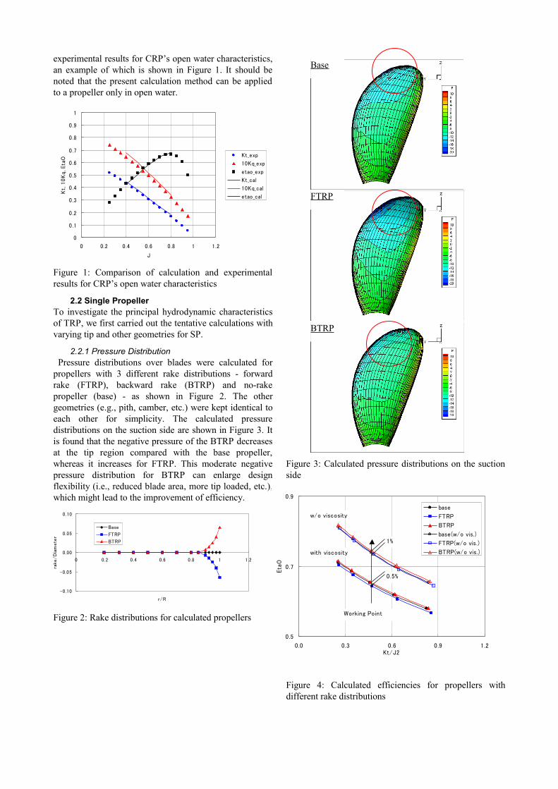
2.2.1 Pressure Distribution Pressure distributions over blades were calculated for propellers with 3 different rake distributions - forward rake (FTRP), backward rake (BTRP) and no-rake propeller (base) - as shown in Figure 2. The other geometries (e.g., pith, camber, etc.) were kept identical to each other for simplicity. The calculated pressure distributions on the suction side are shown in Figure 3. It is found that the negative pressure of the BTRP decreases at the tip region compared with the base propeller, whereas it increases for FTRP. This moderate negative pressure distribution for BTRP can enlarge design flexibility (i.e., reduced blade area, more tip loaded, etc.), which might lead to the improvement of efficiency.
Figure 2: Rake distributions for calculated propellers
Figure 3: Calculated pressure distributions on the suction side
Figure 4: Calculated efficiencies for propellers with different rake distributions
0
0 .1
0 .2
0 .3
0 .4
0 .5
0 .6
0 .7
0 .8
0 .9
1
0 0.2 0.4 0 .6 0.8 1 1.2
J
Kt,
10K
q, E
taO
Kt_exp
10Kq_exp
etao_exp
Kt_cal
10Kq_cal
etao_cal
-0.10
-0.05
0.00
0.05
0.10
0 0.2 0.4 0.6 0.8 1 1.2
r/R
rake
/D
iam
ete
r
Base
FTRP
BTRP
0.5
0.7
0.9
0.0 0.3 0.6 0.9 1.2Kt/J2
Eta
O
base
FTRP
BTRP
base(w/o vis.)
FTRP(w/o vis.)
BTRP(w/o vis.)
Working Point
w/o viscosity
with viscosity
1%
0.5%
Base
FTRP
BTRP
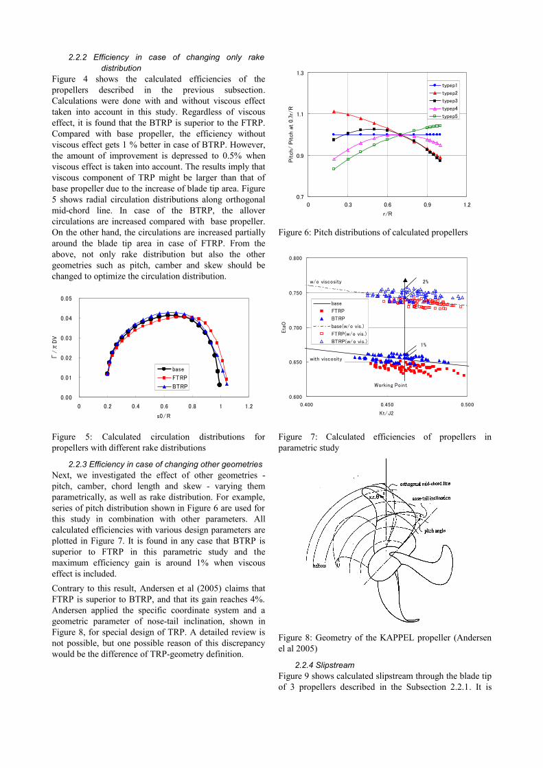
2.2.2 Efficiency in case of changing only rake distribution
Figure 4 shows the calculated efficiencies of the propellers described in the previous subsection. Calculations were done with and without viscous effect taken into account in this study. Regardless of viscous effect, it is found that the BTRP is superior to the FTRP. Compared with base propeller, the efficiency without viscous effect gets 1 % better in case of BTRP. However, the amount of improvement is depressed to 0.5% when viscous effect is taken into account. The results imply that viscous component of TRP might be larger than that of base propeller due to the increase of blade tip area. Figure 5 shows radial circulation distributions along orthogonal mid-chord line. In case of the BTRP, the allover circulations are increased compared with base propeller. On the other hand, the circulations are increased partially around the blade tip area in case of FTRP. From the above, not only rake distribution but also the other geometries such as pitch, camber and skew should be changed to optimize the circulation distribution.
Figure 5: Calculated circulation distributions for propellers with different rake distributions
2.2.3 Efficiency in case of changing other geometriesNext, we investigated the effect of other geometries - pitch, camber, chord length and skew - varying them parametrically, as well as rake distribution. For example, series of pitch distribution shown in Figure 6 are used for this study in combination with other parameters. All calculated efficiencies with various design parameters are plotted in Figure 7. It is found in any case that BTRP is superior to FTRP in this parametric study and the maximum efficiency gain is around 1% when viscous effect is included. Contrary to this result, Andersen et al (2005) claims that FTRP is superior to BTRP, and that its gain reaches 4%. Andersen applied the specific coordinate system and a geometric parameter of nose-tail inclination, shown in Figure 8, for special design of TRP. A detailed review is not possible, but one possible reason of this discrepancy would be the difference of TRP-geometry definition.
Figure 6: Pitch distributions of calculated propellers
Figure 7: Calculated efficiencies of propellers in parametric study
Figure 8: Geometry of the KAPPEL propeller (Andersen el al 2005)
2.2.4 SlipstreamFigure 9 shows calculated slipstream through the blade tip of 3 propellers described in the Subsection 2.2.1. It is
0.7
0.9
1.1
1.3
0 0.3 0.6 0.9 1.2
r/R
Pitch/
Pitch a
t 0.7
r/R
typep1
typep2
typep3
typep4
typep5
0.00
0.01
0.02
0.03
0.04
0.05
0 0.2 0.4 0.6 0.8 1 1.2
s0/R
Γ/π
DV
base
FTRP
BTRP
0.600
0.650
0.700
0.750
0.800
0.400 0.450 0.500
Kt/J2
Eta
O
base
FTRP
BTRP
base(w/o vis.)
FTRP(w/o vis.)
BTRP(w/o vis.)
w/o viscosity
with viscosity
Working Point
2%
1%

found that the streamline changes according to the shift of the blade tip position. At the aft propeller’s position, the slipstream diameter of the BTRP is larger than that of the base propeller. The change of slipstream diameter at the aft propeller is one of the most important characteristics when TRP concept is applied to CRP. Aft propeller of CRP works in the slipstream of forward propeller and its diameter must be smaller than the streamline diameter to avoid a forward propeller’s tip vortex. From the general principle by momentum theory, propeller efficiency is improved as propeller diameter is enlarged. Applying the BTRP to forward propeller, aft propeller can be enlarged more which leads to the further improvement of CRP’s efficiency.
Figure 9: Slipstream of propellers with different rake distributions
2.3 CRPThe same approach as described in 2.2 was applied to CRP design with tip-raked fins. Table 1 shows the calculated results for the CRP with different rake-combination. In this case, the other geometries were kept identical to each other. The resultant ranking of efficiency is BB>BF>FB>FF, as shown in the table. CRP with the BTRP geometry is superior to that with the FTRP, which shows similar results in case of SP-TRP design. The tendencies for the changes of pressure and circulation distribution are also similar to those for the single propeller case.
Table 1: Calculated results for CRPs with different rake distributions
3 DESIGN OF TIP-RAKED CRP Based on the studies mentioned, new tip-raked CRP was designed under the following concept, aimed at improving its efficiency:
1) Applying backward tip rake to forward propeller with the aim of maximizing aft propeller diameter within a slipstream of forward propeller;
2) Utilizing advantage of moderate negative pressure distribution on the suction side of BTRP, optimize forward propeller’s geometries within an allowable range of cavitation performance.
Figure 10 shows an illustration of the designed tip-raked CRP. To maximize aft propeller diameter, aft propeller has a little forward rake. Table 2 shows the dimensions of the conventional CRP without curved rake (CRP1) and the designed CRP with tip rake (CRP2) in model scale. Both CRPs were designed under the same design condition to keep the same thrust.
Figure 10: Illustration of the designed CRP
Table 2: Dimensions of designed CRP and based CRP
4 MODEL TESTSSubsequently, the model tests were carried out to verify the performance of the CRPs in Table 2. In addition, model tests for each aft and forward propeller were also carried out as a single propeller mode.
4.1 ConditionsIt is known that TRP is strongly influenced by viscous effect and, thus, open water tests for TRP should be carried out at high Reynolds number (Andersen et al 2005). To meet this requirement, open water tests were carried out at HSVA’s high speed cavitation tunnel, increasing flow speeds up to 7 m/s with model propellers of up to 360 mm diameters.
Aft Propeller’s position
Forward Aft Forward AftModel Number MP2955 MP2956 MP2957 MP2958
Number of Blades 4 5 4 5Direction of Rotation right left right left
Diameter (mm) 360 300 360 329.5Pitch Ratio at 0.7R 0.86 1.059 0.859 1.087
Rake Straight StraightBackwardTip Rake
ForwardTip Rake
CRP1 (Base) CRP2 (TRP)
Case Forward Aft J Kt 10Kq etaO etaO_gain
Base No rake No rake 0.55 0.302 0.464 0.570 baseBF BTRP FTRP 0.55 0.302 0.463 0.571 0.2%BB BTRP BTRP 0.55 0.302 0.458 0.578 1.5%FB FTRP BTRP 0.55 0.302 0.466 0.567 -0.4%FF FTRP FTRP 0.55 0.302 0.472 0.560 -1.7%

4.2 Open Water Tests ResultsFigure 11 shows the comparison between calculation and experimental results for both CRPs. Both calculation and experiment show that efficiency of CRP2 (designed CRP) was improved compared with the CRP1 (base CRP). However, 1.5% efficiency gain derived from experiment is smaller than estimated one. The above discrepancy would be raised by the forward propeller’s efficiency in single mode, and so, not as improved as expected, as shown in Figure 12. That is, optimization of forward propeller is still insufficient whereas aft propeller diameter could be increased as arranged. Further, in spite of the intention to keep Kt for both forward propellers, Kt for TRP is smaller than that of the base propeller as shown in Figure 13. However, the reasons of this discrepancy are not clear up to now. Compared with the conventional propeller (e.g., without curved rake), larger viscous effect appears on TRP as described in the next chapter and the surrounding flow field at the tip region should be more complex. So, inaccuracy for the estimation of viscous effect and trailing wake vortex might be major reasons. To improve the calculation accuracy for TRP, more detailed investigations are necessary.
4.3 Reynolds Number DependencyFigure 14 shows the Reynolds dependency of the both CRP and each propeller in single mode at the respective working point (J=0.55 for CRPs, J=0.6 for forward propellers, and J=0.7 for aft propellers). It is found that efficiencies of TRP change steeply compared with the base propeller in both case of CRP and single propeller mode. From these findings, it seems necessary to carry out open water tests for TRP over Reynolds number of 1*106.
Figure 11: Comparison of efficiencies of CRP1 (base) and CRP2 (TRP), experimental results are at Reynolds number=1.4*106
Figure 12: Comparison of efficiencies of CRP1’s forward propeller (base) and CRP2’s forward propeller (TRP), experimental results are at Reynolds number=1.4*106
Figure 13: Comparison of open water characteristics of CRP1’s forward propeller (base) and CRP2’s forward
Figure 14: Reynolds dependencies of CRP1 and CRP2
4.4 Trajectory of Forward Propeller’s Tip Vortex During open water tests, trajectory of forward propeller’s tip vortex was visualized by depressing static pressure of the tank. As shown in Figure 15, it was observed that the aft propeller works within the trajectory and the tip vortex didn’t hit the aft propeller blade. Although it is necessary
0
0.1
0.2
0.3
0.4
0.5
0.6
0.7
0.8
0.2 0.4 0.6 0.8 1 1.2
J
Kt, 1
0K
q, E
taO
Kt_CRP1(base)
10Kq_CRP1(base)
etaO_CRP1(base)
Kt_CRP2(TRP)
10Kq_CRP2(TRP)
EtaO_CRP2(TRP)
0.5
0.65
0.8
0 0.5 1 1.5
Kt/J2
Eta
O
CRP1_fore(base)_exp
CRP2_fore(TRP)_exp
CRP1_fore(base)_cal
CRP2_fore(TRP)_cal
Efficiency gainCalculation 1.5%Experiment 0.1%
Working Point
0.50
0.65
0.80
1.E+05 1.E+06 1.E+07
Reynold's Number (Kempf)
Eta
O
CRP1_fore
CRP1_aft
CRP2_fore
CRP2_aft
CRP1
CRP2
0.5
0.65
0 .8
0 0.5 1 1.5 2
Kt/J2
Eta
O
CRP1(base)_exp
CRP2(TRP)_exp
CRP1(base)_cal
CRP2(TRP)_cal
Efficiency gainCalculation 3%Experiment 1.5%
Working Point

to investigate cavitation behavior in ship wake field, the basic concept to enlarge aft propeller diameter inside the slipstream of forward propeller goes well in homo flow.
Figure 15: Pictures of the trajectory of tip vortex of the CRP
5 ConclusionTo improve CRP’s efficiency further, we applied tip-raked fins to conventional CRP and its performance was verified by model tests and calculations. Concluding remarks are summarized as follows:1) From the investigation of basic characteristics of
TRP by potential calculation, negative pressure on the suction side is moderated by backward tip rake;
2) According to the calculation, it is found that the slipstream moves according to the shift of the blade tip position. By applying backward tip rake to forward propeller, aft propeller diameter can be increased which leads to the improvement of efficiency;
3) CRP with increased aft propeller diameter was designed and its performance was verified by model tests in HSVA’s high speed cavitation tunnel. The efficiency of the designed CRP with tip rake was improved by 1.5% compared with the conventional CRP without curved rake;
4) It is found by the model test that the viscous effect for TRP is larger than that for the conventional propeller;
5) According to the calculation, the efficiency of propeller with backward rake is improved compared with the conventional propeller. However, its model tests show no gain from the conventional propeller.
In this study, the improvement of CRP efficiency has been attained by application of tip-raked propeller. To improve the performance of the tip-raked CRP more, the following items should be investigated in the future: 1) Accurate calculation method for TRP and application
of the present method to a wake adapted propeller;2) Cavitation behavior of tip-raked CRP in ship wake;3) Self-propulsion factors with tip-raked CRP.
REFERENCESAndo, J., Maita, S. & Nakatake, K. (1995). ʻA Simple
Surface Panel Method to Predict Steady Marine Propeller Performance’. Journal of the Society of Naval Architects of Japan 178.
Cone, Jr. C. D. (1962). ‘The theory of induced lift and minimum drag of nonplanar lifting systems’. NASA Technical Report R-139.
Kawakita, C. (1992). ‘A Surface Panel Method for Ducted Propellers with New Wake Model Based on Velocity Measurements’. Journal of the Society of Naval Architects of Japan 172.
Inukai, Y. (2010). ‘A Development of the Electric Propulsion Vessels with Contra-Rotating Propeller’. International Propulsion Symposium 2010, Japan.
Andersen, P., Friesch, J., Kappel, J. J., Lundegaard, L. & Patience, G. (2005). ‘Development of a Marine Propeller with Non-Planar Lifting Surfaces’. Marine Technology 42(3).
Suzuki, K., Fukumori, S. & Mizuno, S. (2002). ‘A Study for Tip-Raked Propeller’. The Hitachi Zosen Technical Review 62 (4).
Yamasaki, S. & Okazaki, A. (2005). ‘Cavitation test on a straight leading edge propeller and a tip rake propeller’. Journal of the Japan Society of Naval Architect and Ocean Engineers 2.