Development of an Electric induction furnace for heat treatment of ferrous and non-ferrous alloys
7
American Journal of Engineering Research (AJER) 2015 American Journal of Engineering Research (AJER) e-ISSN: 2320-0847 p-ISSN : 2320-0936 Volume-4, Issue-5, pp-29-35 www.ajer.org Research Paper Open Access www.ajer.org Page 29 Development of an Electric induction furnace for heat treatment of ferrous and non-ferrous alloys Ufuoma Peter Anaidhuno 1 ; Chinedum Ogonna Mgbemena 2 1,2 Department of Mechanical Engineering, Federal University of Petroleum Resources, Effurun, Nigeria ABSTRACT : A 3kg capacity Electric induction furnace with a power rating of 2500W for heat treatment of ferrous and non-ferrous alloys was developed. The furnace which is made from mild steel sheet was monolithically lined with fire clay refractories and designed to attain a temperature of 1200 0 C on the automatic control panel. This project was primarily undertaken to build local capacity in foundry practice in Nigeria and to encourage the demonstration of fundamental foundry practice for undergraduates of a Nigerian Universit y. KEYWORDS -Furnace, Temperature, induction, Foundry, Ferrous, Non-ferrous I. INTRODUCTION 1.1 Background of the Study Electric Induction heating is a non-contact heating process which is used to bond, harden or soften metals or other conductive materials [1, 2]. In advanced manufacturing processes, induction heating provides an appealing assemblage of speed, consistency and control. Induction heating has a good heating efficiency, high production rate and clean working environments. The fundamentals of induction heating have been apprehended and utilized in manufacturing since the 19 th century [1, 3, 4]. Historically, the early development of Induction furnaces started from the discovery of the principle of electromagnetic induction by Michael Faraday. However, De Ferranti in the late 1870s started experimenting with induction furnaces in Europe. Edward Allen Colby patented an induction furnace for melting metals in the year 1890 and produced the first steel the United States in 1907 [5]. During World War II, the technology grew rapidly to satisfy pressing wartime demands for a quick and authentic method of hardening metal engine parts. Lately, the concentration on lean manufacturing techniques and emphasis on improved quality control have led to a rediscovery of induction technology, along with the development of precisely controlled solid state induction power supplies [1]. In a majority of the heating methods, a torch or open flame is instantly applied to the metal part, but with induction heating, heat is actually "induced" within the part itself by circulating electrical currents [1]. On account of heat being transferred to the product through electromagnetic waves of which the part never comes into direct contact with any flame, there is no product contamination and when duly set up, the process can be replicated and controlled. This dissertation deals on the construction of an electric heat treatment furnace with easier and better control system and timing unit. Typical applications of induction heating are melting of metals, heating of metals, brazing and welding and all sorts of surface treatments. However, by using electric conductive recipients (e.g. graphite) also other materials like glass can be heated. Surface hardening techniques are suitable for steel with a carbon percentage of at least 0.3 %, where the work piece is heated up to approximately 900°C and after that it is chilled [4]. This technique is used for the hardening of gear wheels, crankshafts, valve stems, saw blades, spades, rails, and many other things. The inductive process has the advantage that the treatment can be localized very accurately.
-
Upload
ajer123 -
Category
Technology
-
view
92 -
download
9
Transcript of Development of an Electric induction furnace for heat treatment of ferrous and non-ferrous alloys

American Journal of Engineering Research (AJER) 2015
American Journal of Engineering Research (AJER)
e-ISSN: 2320-0847 p-ISSN : 2320-0936
Volume-4, Issue-5, pp-29-35
www.ajer.org Research Paper Open Access
w w w . a j e r . o r g
Page 29
Development of an Electric induction furnace for heat treatment
of ferrous and non-ferrous alloys
Ufuoma Peter Anaidhuno1; Chinedum Ogonna Mgbemena
2
1,2Department of Mechanical Engineering, Federal University of Petroleum Resources, Effurun, Nigeria
ABSTRACT : A 3kg capacity Electric induction furnace with a power rating of 2500W for heat treatment of
ferrous and non-ferrous alloys was developed. The furnace which is made from mild steel sheet was
monolithically lined with fire clay refractories and designed to attain a temperature of 12000C on the automatic
control panel. This project was primarily undertaken to build local capacity in foundry practice in Nigeria and
to encourage the demonstration of fundamental foundry practice for undergraduates of a Nigerian University.
KEYWORDS -Furnace, Temperature, induction, Foundry, Ferrous, Non-ferrous
I. INTRODUCTION
1.1 Background of the Study Electric Induction heating is a non-contact heating process which is used to bond, harden or soften
metals or other conductive materials [1, 2]. In advanced manufacturing processes, induction heating provides an
appealing assemblage of speed, consistency and control. Induction heating has a good heating efficiency, high
production rate and clean working environments. The fundamentals of induction heating have been apprehended
and utilized in manufacturing since the 19th
century [1, 3, 4]. Historically, the early development of Induction
furnaces started from the discovery of the principle of electromagnetic induction by Michael Faraday. However,
De Ferranti in the late 1870s started experimenting with induction furnaces in Europe. Edward Allen Colby
patented an induction furnace for melting metals in the year 1890 and produced the first steel the United States
in 1907 [5].
During World War II, the technology grew rapidly to satisfy pressing wartime demands for a quick and
authentic method of hardening metal engine parts. Lately, the concentration on lean manufacturing techniques
and emphasis on improved quality control have led to a rediscovery of induction technology, along with the
development of precisely controlled solid state induction power supplies [1]. In a majority of the heating
methods, a torch or open flame is instantly applied to the metal part, but with induction heating, heat is actually
"induced" within the part itself by circulating electrical currents [1]. On account of heat being transferred to the
product through electromagnetic waves of which the part never comes into direct contact with any flame, there
is no product contamination and when duly set up, the process can be replicated and controlled. This
dissertation deals on the construction of an electric heat treatment furnace with easier and better control system
and timing unit.
Typical applications of induction heating are melting of metals, heating of metals, brazing and welding
and all sorts of surface treatments. However, by using electric conductive recipients (e.g. graphite) also other
materials like glass can be heated. Surface hardening techniques are suitable for steel with a carbon percentage
of at least 0.3 %, where the work piece is heated up to approximately 900°C and after that it is chilled [4]. This
technique is used for the hardening of gear wheels, crankshafts, valve stems, saw blades, spades, rails, and many
other things. The inductive process has the advantage that the treatment can be localized very accurately.

American Journal of Engineering Research (AJER) 2015
w w w . a j e r . o r g
Page 30
II. MATERIALS AND METHODOLOGY
This chapter introduces the materials and methods employed in the design and development of the electric
induction heat treatment furnace.
2.1 Materials The materials utilized for the design a n d development of the Electric heat-treatment furnace are: 1.5
mm thick steel sheets, kaolin clay, hard wood saw dust, temperature controller, switch, light indicators, wire,
heating element-copper coil. Tables 1-2 show the detailed materials used in the development of the electric heat
treatment furnace and their cost implications. The total costs for a unit is $862 (Eight hundred and sixty two
dollars).
2.2 Furnace casing The steel sheet selected is a mild steel of composition: 0.15% C, 0.45% Mn, 0.18% Si, 0.031% S,
0.001% P, 0.0005% Al, 0.0008% Ni and 0.1867% Fe. It was selected for the fabrication of the furnace casing
because of its light weight, good strength, excellent formability, weldability, availability, and low cost of
purchase. The furnace casing houses all the components of the furnace including: the refractory bricks and
lining, the electro-technical devices (temperature controller, light indicator etc.), the coils. The design was
made taking into consideration that the control box should be attached to the casing, and the control box must
have holes for easy wiring. The casing was made from a 1.5mm thick flat sheet of mild steel. The sheet was
cut to size of 500mm and then folded into box shape. The folding joint was seam welded for strength and
rigidity.
2.3 Design/Model Drawings
The design/model drawings of the furnace were achieved using AUTOCAD. Figures 1-11 show the
various views and sections of the electric heat treatment furnace developed.
Figure 1 Skeletal Frame Work of the Furnace.
Figure 2 Furnace Pictorial view with Detailed Dimensions

American Journal of Engineering Research (AJER) 2015
w w w . a j e r . o r g
Page 31
Figure 3 Section A-A of the Furnace
Figure 4 Section B-B of the Furnace
Figure 5 Section C-C of the Furnace
Figure 6 Back View of the Furnace.
American Journal of Engineering Research (AJER) 2015
w w w . a j e r . o r g
Page 32
Figure 7 Parts of the Furnace
Figure 8 Furnace with the Door Opened and Closed
Figure 9 Autographic Projection of the Furnace
Figure 10 Labeled Furnace Parts
American Journal of Engineering Research (AJER) 2015
w w w . a j e r . o r g
Page 33
Figure 11 Dis-Assembling Drawing
Table 1 List of Materials, Their Source and Function
S/N MATERIAL SOURCE FUNCTIONS
1 Metal sheet Diamond Metraco
International Ltd, 1387
Bridge Head Market,
Onitsha
Metal sheet was used to build the casing or panel of the
furnace.
It is capable to withstand high temperature
It hardly gets burnt
It has the tendency to withstand sagg
2 Angle iron Zonal Steel company, A377
Bridge Head Market,
Onitsha
It acts as a reinforcement to the casing and through
which the legs are provided
3 Asbestos
sheet
Naze Timber shop, Owerri This contributes to retain the heat in the furnace i.e. it
prevents heat loss.
It prevents damage to the metal casing by preventing
excess heat that mat burn the metal body or cause
corrosion
4 Fire clay Nwanneji & Sons (Nig)
Itape
This was used for casting.
It has the tendency to withstand crack and breakage
when heated.
It has the ability to retain heat
5 Beads Bridge Head Market Onitsha They act as insolators to prevent current from escaping
the induction coils.
The prevent shock
6 Induction
coils
Rusana Electrical store, No.
65 Old Aba Road PH
It produces heat for heat treatment
7 Temperature
relay
Rusana Electrical store, No.
65 Old Aba Road PH
It displays the temperature of the furnace.
It displays working principles
8 Circuit
breaker
Rusana Electrical store, No.
65 Old Aba Road PH
It controls the working principles of the electrical parts
9 Switch Rusana Electrical store, No.
65 Old Aba Road PH
It acts as the powering section of the furnace
10 Indicators Rusana Electrical store, No.
65 Old Aba Road PH
One indicates power ON and OFF, the other indicates
danger
11 Electrodes Elinus and son Enterprises,
Steel Market, Owerri
It was used for the joining and welding together of
components
12 Water School borehole It was used to make the solution of fire clay and silica
13 Cable Onitsha For the connection and wiring of the electrical and
power systems
14 Fuse Rusana Electrical store, No.
65 Old Aba Road PH
For the transfer and grip of current
15 Filler Shop 35 A, New market,
Owerri
It was used for filling up of opened regions on the
panel
16 Paint Shop 35A New market,
Owerri
It was used for the nice looking and finishing of the
project
17 Template University workshop It was used for the excavation of the opening for heat
treatment portion
American Journal of Engineering Research (AJER) 2015
w w w . a j e r . o r g
Page 34
Table 2 Bill for Engineering Measurement and Evaluation
S/N MATERIAL QUANTITY UNIT COST
($)
TOTAL COST
($)
1 Metal sheet (1.5mm) 1 36 36
2 Angle iron 2X2 1 31 31
3 Template - 16 16
4 Asbestos ¼ roll 13 13
5 Fire clay 3 bags 47 141
6 Purslin Beads 200 0.5 100
7 Heating Element 5 9 45
8 Temperature relay 1 128 128
9 Circuit breaker 1 31 31
10 Switch 1 5 5
11 Indicators 2 2.6 5.2
12 Electrodes 1 10.25 10.25
13 Cable/wire 15Meters 1.30 19.5
14 Fuse 1 5 5
15 Filler - - 8
16 Paint 1 13 13
17 Transportation/Logistics 105
18 Labour costs 150
Total $861.95
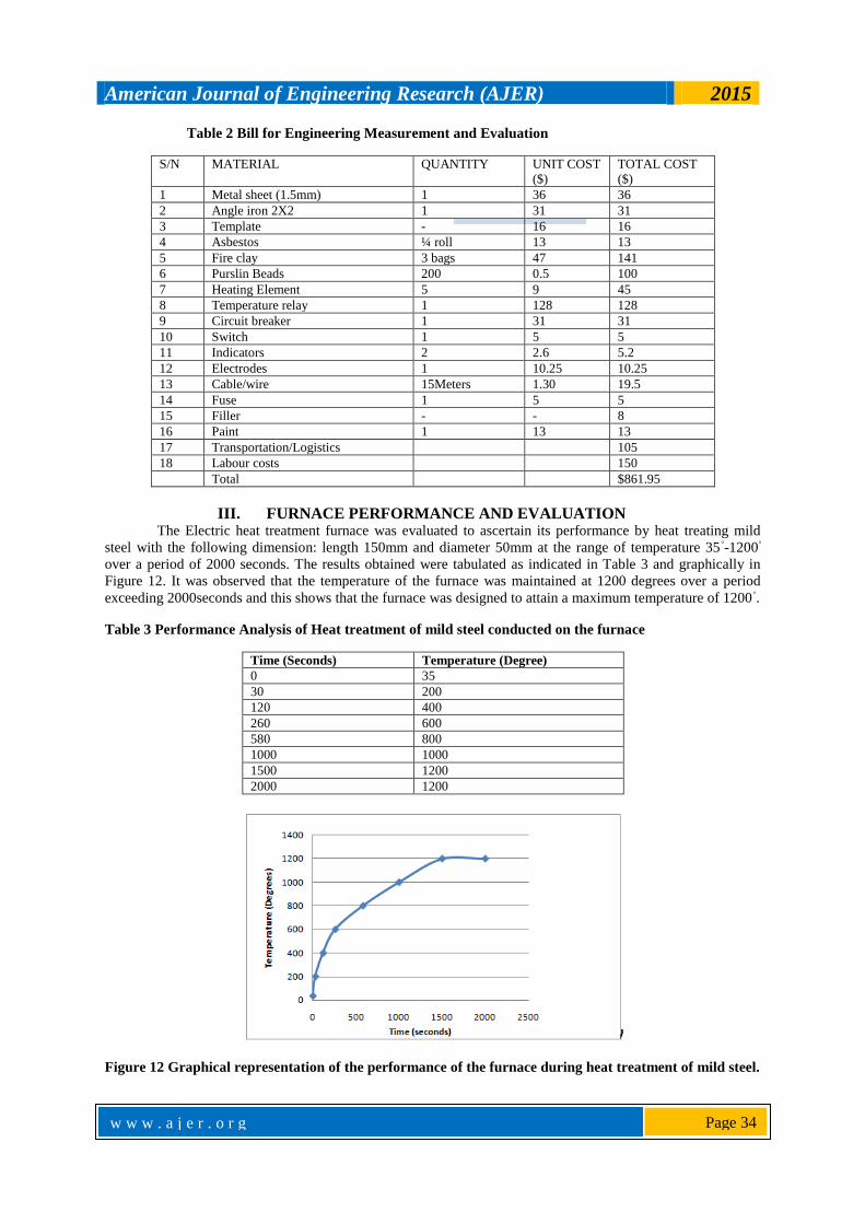
III. FURNACE PERFORMANCE AND EVALUATION The Electric heat treatment furnace was evaluated to ascertain its performance by heat treating mild
steel with the following dimension: length 150mm and diameter 50mm at the range of temperature 35◦-1200
◦
over a period of 2000 seconds. The results obtained were tabulated as indicated in Table 3 and graphically in
Figure 12. It was observed that the temperature of the furnace was maintained at 1200 degrees over a period
exceeding 2000seconds and this shows that the furnace was designed to attain a maximum temperature of 1200◦.
Table 3 Performance Analysis of Heat treatment of mild steel conducted on the furnace
Time (Seconds) Temperature (Degree)
0 35
30 200
120 400
260 600
580 800
1000 1000
1500 1200
2000 1200
Figure 12 Graphical representation of the performance of the furnace during heat treatment of mild steel.

American Journal of Engineering Research (AJER) 2015
w w w . a j e r . o r g
Page 35
IV. CONCLUSION
This project was undertaken to design and develop an electric induction heat treatment furnace for
undergraduate students’ demonstrations on heat treatment processes such as annealing, normalizing, case
hardening, tempering, spheroidizing etc. in the Mechanical Engineering Foundry Shop. The furnace was
constructed putting into consideration; its temperature attainment, capacity of metals it can hold, the
depth/surface area to be heat treated, operators safety, space to be occupied in the workshop floor, cost
restrictions, availability of the materials used, its maintainability and portability .
Finally, the actualization and realization of this project is a boost to the development of local
manpower capacity in Nigeria and also to advance the reliability of engineering materials in service.
REFERENCES [1]. http://www.gh-ia.com › Induction Heating retrieved on 29/1/2015.
[2]. http://www.inductivelogic.co.uk/induction-heating-products.html retrieved on 29/1/2015. [3]. Bala, K.C. (2005). Design Analysis of an Electric Induction Furnace for Melting Aluminum Scrap, AU J.T. 9(2): 83-88.
[4]. Anaidhuno, P. U. (2014). Construction of an Electric Heat Treatment Furnace, M. Eng Thesis; Mechanical Engineering Department;
Anambra State University, Nigeria.
[5]. Gandhewar, V.R., Bansod, S.V., Borade, A.B.(2011).Induction Furnace-A Review,International Journal of Engineering and
Technology Vol.3 (4), 277-284.