DEVELOPMENT OF AN AUTOMATED SYSTEM FOR · PDF fileDEVELOPMENT OF AN AUTOMATED SYSTEM FOR...
10
DEVELOPMENT OF AN AUTOMATED SYSTEM FOR MANEUVERING PARABOLIC DISH ANTENNAS USED IN SATELLITE COMUNICATION Marcos César Rafael, [email protected] Foundation João Paulo II – Department of Broadcasting Rua João Paulo II, s/n – CEP: 12630-000 – Cachoeira Paulista, SP - Brasil João Bosco Gonçalves, [email protected] Pedro Paulo Leite do Prado, [email protected] University of Taubaté (UNITAU) – Department of Electrical Engineering Rua Daniel s/n (Campus da Juta) – CEP: 12060-440 – Taubaté, SP - Brasil Abstract. The automation in all its aspects has become widespread and promises to represent the future for information technology, according to some researchers. This paper aims to present and discuss the results from the development of an automated system for maneuvering of the parabolic reflector antennas of a satellite communication. This work automates the key steps involved in the manual maneuvering of an antenna dish. Based on procedures for the manual maneuvering a satellite dish, was proposed an architecture that employs hardware solutions and software. It was added to the platform a GPS antenna to monitor the spatial location, and a digital receiver, which provides the value for the carrier-to-noise ratio, C/N. The main focus of this work was to design and develop in Java, a Control System Antenna Maneuvering, 3SA that can process the information of the spatial position of the antenna, generating a reference signal for a servo capable of processing the C/N and making a fine adjustment of the position of the antenna in order to improve signal reception. The user can select the desired satellite and monitor the process of automatic annotation, through a set of user-friendly graphical interfaces. In the context of this work, we found that even if the antenna is in a desired position, the C/N ratios should be above a minimum value for a good reception. Consequently, it was necessary to design a control system to fine-tuning the antenna position. Our approach in this case was to use a fuzzy controller which employed 63 rules, generated according to rules of thumb used in the process of manual maneuvering a satellite dish. This solution allowed for better placement of the antenna and therefore a C/N ratio above the minimum for good reception. The experimental results showed a perfect match for our approach to automate the key steps manual maneuvering an antenna dish. Keywords: automation, object-orientation, antenna maneuvering, system development. 1. INTRODUCTION The maneuvering of satellite dishes is currently performed manually wasting many hours to perform this process. Basically, for the manual, we use a spectrum analyzer to monitor the signal during movement of the antenna until the desired satellite is found. Also, to look for the location of a satellite in order to achieve the best reception is an exhaustive process. Figure 1 illustrates a professional application of parabolic antennas: a satellite communication system to send and receive TV, radio and internet. The parabolic antennas have a high cost, that depends on the diameter of the antenna. Since each antenna is dedicated to a satellite, it is difficult to point it. So, it is necessary an automated system in order to achieve the optimum positioning for reception of the signal. ABCM Symposium Series in Mechatronics - Vol. 5 Copyright © 2012 by ABCM Section II – Control Systems Page 69
Transcript of DEVELOPMENT OF AN AUTOMATED SYSTEM FOR · PDF fileDEVELOPMENT OF AN AUTOMATED SYSTEM FOR...

DEVELOPMENT OF AN AUTOMATED SYSTEM FOR MANEUVERING
PARABOLIC DISH ANTENNAS USED IN SATELLITE COMUNICATION
Marcos César Rafael, [email protected] Foundation João Paulo II – Department of Broadcasting
Rua João Paulo II, s/n – CEP: 12630-000 – Cachoeira Paulista, SP - Brasil
João Bosco Gonçalves, [email protected]
Pedro Paulo Leite do Prado, [email protected] University of Taubaté (UNITAU) – Department of Electrical Engineering
Rua Daniel s/n (Campus da Juta) – CEP: 12060-440 – Taubaté, SP - Brasil
Abstract. The automation in all its aspects has become widespread and promises to represent the future for
information technology, according to some researchers. This paper aims to present and discuss the results from the
development of an automated system for maneuvering of the parabolic reflector antennas of a satellite communication. This work automates the key steps involved in the manual maneuvering of an antenna dish. Based on procedures for
the manual maneuvering a satellite dish, was proposed an architecture that employs hardware solutions and software.
It was added to the platform a GPS antenna to monitor the spatial location, and a digital receiver, which provides the
value for the carrier-to-noise ratio, C/N. The main focus of this work was to design and develop in Java, a Control
System Antenna Maneuvering, 3SA that can process the information of the spatial position of the antenna, generating a
reference signal for a servo capable of processing the C/N and making a fine adjustment of the position of the antenna
in order to improve signal reception. The user can select the desired satellite and monitor the process of automatic
annotation, through a set of user-friendly graphical interfaces. In the context of this work, we found that even if the
antenna is in a desired position, the C/N ratios should be above a minimum value for a good reception. Consequently,
it was necessary to design a control system to fine-tuning the antenna position. Our approach in this case was to use a
fuzzy controller which employed 63 rules, generated according to rules of thumb used in the process of manual
maneuvering a satellite dish. This solution allowed for better placement of the antenna and therefore a C/N ratio above
the minimum for good reception. The experimental results showed a perfect match for our approach to automate the
key steps manual maneuvering an antenna dish.
Keywords: automation, object-orientation, antenna maneuvering, system development.
1. INTRODUCTION
The maneuvering of satellite dishes is currently performed manually wasting many hours to perform this process.
Basically, for the manual, we use a spectrum analyzer to monitor the signal during movement of the antenna until the
desired satellite is found. Also, to look for the location of a satellite in order to achieve the best reception is an
exhaustive process.
Figure 1 illustrates a professional application of parabolic antennas: a satellite communication system to send and
receive TV, radio and internet. The parabolic antennas have a high cost, that depends on the diameter of the antenna.
Since each antenna is dedicated to a satellite, it is difficult to point it. So, it is necessary an automated system in order to
achieve the optimum positioning for reception of the signal.
ABCM Symposium Series in Mechatronics - Vol. 5 Copyright © 2012 by ABCM
Section II – Control Systems Page 69

Figure 1 – Satellite communication system
Many works addressed the antenna control system realization.
Chang-ho, Sang-hyo (2003) developed a control method using an antenna step tracking algorithm with 𝐻∞
controller. This required to develop a discrete-time controller for the fast tracking of the satellite. The method applies
the sample data control theory 𝐻∞ . The real-time controllers are implemented using the CEMTOOL software and the
DSP/IO board (RG-DSPIO). Block algorithms are transformed into C codes by AUTOTOOLS in CEMTOOLS and
downloaded to the DSP board in order to execute experiments. In implementing the step algorithm, it was verified that
the performance of the antenna tracking system largely depends on step sizes through repeated experiments. The results
of this work through samples of 𝐻∞ controller data, demonstrate the robustness of the method compared with the
conventional PID controller.
Jongkwon et al. (2006) developed a method for controlling an antenna mounted on a vehicle. This required to design
a fuzzy controller to control the tracking antenna. The method was developed from the stabilization of fuzzy rule-based
tracking algorithm. With the stabilizing the tracking algorithm, the PID fuzzy controller was determined. The
performance of the method was verified through simulations with Matlab® and Simulink
® software. The data obtained
were compared with the conventional PID controller. The result of this work indicated that the fuzzy PID controller has
better performance than the conventional PID controller.
Our new approach address the key steps involved in manually maneuvering a satellite dish to generate design
solutions called Automatic Antenna Maneuvering, S3A. Our method, S3A, incorporates a database containing
information about the satellites available in our country, used for transmission in broadcasting. After the choice of a
satellite, S3A generates the reference position for the antenna, which will be used by a servomechanism. S3A offers
many user-guided-interfaces that provide information about the movement of the antenna toward the reference position,
the spatial position of the antenna and the C/N ratio. After the antenna reaches the reference position, S3A monitors the
quality of the reception through the C/N ratio. For a good reception quality, the C/N ratio must be at least 8 dB (HA,
1986). If this ratio is below of this value, the S3A realize the fine adjustment of the antenna position through
servomechanism small movements around the beam width (Esteves, 1980).
2. TECHNICAL MANEUVERING MANUAL
Basically, in the manual maneuvering is necessary: a receiver decoder digital satellite set at a desired frequency, a
spectrum analyzer; a C band parabolic antenna, coaxial cable, and RF signal splitter. Manual maneuvering the parabolic
antenna to search for the location of a satellite is exhaustive processes to achieve a C/N ratio above a minimum value
for a good reception.
The parabolic antenna is manually maneuvered in elevation an azimuth, using a compass and an inclinometer,
respectively.
ABCM Symposium Series in Mechatronics - Vol. 5 Copyright © 2012 by ABCM
Section II – Control Systems Page 70

Figure 2 – Antenna elevation and azimuth angles
The phases of the alignment are:
The antenna is aligned using the calculations of azimuth and elevation angles and observing the signal strength on
the spectrum analyzer;
The receiver provides a signal (control variable) proportional to the signal-to-noise ratio (SNR);
This variable controls the antenna azimuth and elevation in order to achieve the best SNR.
3. MODEL AUTOMATIC MANEUVERING SYSTEM
Our solution comprises the following phases: to construct a database with information about the satellites available
for transmission in broadcasting in Brazil, to calculates and generates the antenna reference position, which will be used
by a servomechanism, to perform the antenna position fine adjustments through small servomechanism movements
around the beam width, and, finally, to offers user-guided-interfaces that will provide information about the spatial
position of the antenna and the C/N ratio.
Figure 3 shows the system architecture proposed for the automatic maneuvering of the satellite: a 3.2 m diameter
antenna dish, a digital satellite receiver to decode the channels of the satellite and a GPS to determine the position of the
antenna.
Figure 3 – Automatic maneuvering system.
Figure 4 is a flowchart of the S3A system.
ABCM Symposium Series in Mechatronics - Vol. 5 Copyright © 2012 by ABCM
Section II – Control Systems Page 71

Figure 4 – Automatic maneuvering system.
The S3A system was divided into three blocks, whose functions are:
- Block 1: realizes the choice of the desired satellite registered in the database and extracts the data. The system
waits for the choice to go to the next step.
- Block 2: carries out the configuration of the GPS and of the digital receiver, extracting the latitude, longitude,
altitude and C/N in order to calculate the values of elevation and azimuth angles (the reference position to the
antenna) an send them to the servomechanism system, using the Control System 1 (SC1). The data obtained
from the communication system are: channel, frequency, symbol rate, forward error control, modulation and
polarization.
- Block 3: performs the management control and a second control (SC2) for moving the antenna, and verifies the
quality of the received signal using the C/N ratio provided by the digital receiver. If the value of the C/N is
greater than or equal to 8 dB, then the pointing process ends the antenna. In this case, it is used a fuzzy
controller which employs 63 rules, generated according to the rules of thumb user in manual maneuvering of
the satellite dish.
ABCM Symposium Series in Mechatronics - Vol. 5 Copyright © 2012 by ABCM
Section II – Control Systems Page 72

3.1 Calculation for the reference position to the antenna
The azimuth can be defined as the angular distance measured on the horizon, from a point of origin, clockwise until
the vertical circle passing through a given satellite (Maral, 2002).
With the geographic coordinates of satellite and the ground station, the azimuth angle can be derived:
 = 𝑎𝑟𝑐𝑡𝑔 𝑡𝑔 ∅𝑠+∅𝑇
𝑠𝑒𝑛 𝜃𝑇 (1)
Where:
𝜃𝑇 Latitude of the earth station;
∅𝑇 Longitude of the earth station;
∅𝑠 Longitude of the satellite.
For the southern hemisphere with the earth station west of the satellite:
ÂA (2)
For the southern hemisphere with the station east of the satellite:
ÂA º360 (3)
For the northern hemisphere with the earth station west of the satellite:
ÂA º180 (4)
For the northern hemisphere with the earth station east of the satellite:
ÂA º180 (5)
The elevation angle is one that exist in the vertical plane between the satellite and earth station antenna. According
to Ha (1986), the value of the elevation angle can be obtained from Eq. (6).
𝐸 = 𝑎𝑟𝑐𝑡𝑔 𝑟−𝑅𝑒 .𝑐𝑜𝑠∅𝑇 .𝑐𝑜𝑠 ∅𝑆−∅𝑇
𝑅𝑒 .𝑠𝑒𝑛 𝑎𝑟𝑐𝑐𝑜𝑠 𝑐𝑜𝑠∅𝑇 .𝑐𝑜𝑠 ∅𝑠−∅𝑇 − 𝑎𝑟𝑐𝑐𝑜𝑠 𝑐𝑜𝑠∅𝑇 . 𝑐𝑜𝑠 ∅𝑆 − ∅𝑇 (6)
Where:
𝑟 radius of the geostationary orbit [42,164 km];
𝑅𝑒 radius of the Earth [6,378 km].
4. SYSTEM AUTOMATIC ANTENNA MANEUVERING
The calculation of elevation and azimuth of the antenna requires the location of the satellite and of the earth station
antenna. The level of the receiver signal is provided by de receiver decoder.
A set of graphical interfaces allows the user to manage the entire automatic maneuvering antenna, attaching the
information on the antenna position and level of desired received signal.
Figure 5 illustrates how the user selects the desired satellite: the system searches the database information for the
chosen satellite, using the GPS information, and then computes the values of the elevation and azimuth.
ABCM Symposium Series in Mechatronics - Vol. 5 Copyright © 2012 by ABCM
Section II – Control Systems Page 73

Figure 5 – Main graphical interface
The system performs the calculation of the pointing and configuration of satellite decoder automatically.
The satellite receiver is plugged into the laptop's serial port, allowing it to be automatically configured by the
software based on Java platform (Reese, 2000).
The computer performs communication via the serial port RS-232 protocol with the satellite receiver to send the
configuration data of the satellite channel and to receive the data signal in a iteration way.
After setting up the receiver, the computer performs the calculation for the antenna placement in a iteration way.
The position of the antenna is obtained from the GPS information that constantly sends to the computer via the serial
port. The system monitors the position of the antenna and recalculates the maneuvering, if necessary.
The system with the information about latitude, longitude and the satellite position performs a mathematical
calculation to obtain the values of azimuth and elevation angles in order to move the antenna.
After calculation, the system stores data in a database. Also, the system, from the movement of the antenna,
evaluates the level of signal-to-noise ratio is ≥ 8 dB.
Thus, the antenna is properly pointed and is receiving a good quality digital signal. If a good quality signal is not
achieved, the system automatically performs a second control, using then fuzzy logic (Ross, 1997) to refine the
maneuvering.
4.1 Fine tuning
Fine tuning aims to improve the antenna gain of the link “antenna - satellite”, after the dish motion. In adverse
conditions, the signal-to-noise ratio can be degraded due to the attenuation by rain, therefore, the importance of the
antenna to have the best C/N ratio to ensure the reliability of the link.
Even when the antenna is in a desired position, the C/N ratio can be below the minimum value for a good reception.
Consequently, it was necessary to design a control system to solve the problem of fine-tuning the antenna position. Our
approach was to use a fuzzy controller which employed 63 rules, generated according to rules of thumb used in the
process of manual maneuvering a satellite dish.
For the project, were considered two inputs, the first is the received signal (signal-to-noise ratio) and the second is
the variation of the error of the received signal. The output was the control signal for the fine motion of the antenna, in
degrees.
In this work we used a Mamdani type inference (Mendel, 1995).
Figure 6 illustrates the implementation of the system, using the software Matlab ® Fuzzy Logic Toolbox.
ABCM Symposium Series in Mechatronics - Vol. 5 Copyright © 2012 by ABCM
Section II – Control Systems Page 74
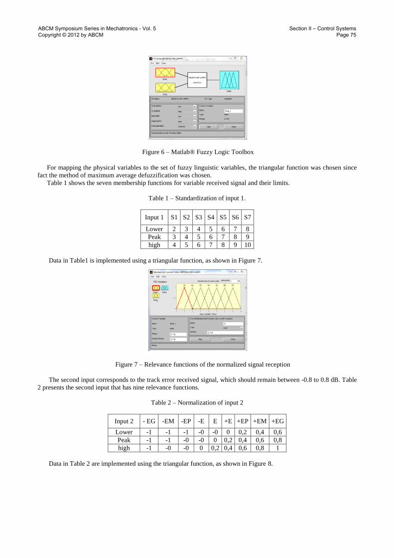
Figure 6 – Matlab® Fuzzy Logic Toolbox
For mapping the physical variables to the set of fuzzy linguistic variables, the triangular function was chosen since
fact the method of maximum average defuzzification was chosen.
Table 1 shows the seven membership functions for variable received signal and their limits.
Table 1 – Standardization of input 1.
Input 1 S1 S2 S3 S4 S5 S6 S7
Lower 2 3 4 5 6 7 8
Peak 3 4 5 6 7 8 9
high 4 5 6 7 8 9 10
Data in Table1 is implemented using a triangular function, as shown in Figure 7.
Figure 7 – Relevance functions of the normalized signal reception
The second input corresponds to the track error received signal, which should remain between -0.8 to 0.8 dB. Table
2 presents the second input that has nine relevance functions.
Table 2 – Normalization of input 2
Input 2 - EG -EM -EP -E E +E +EP +EM +EG
Lower -1 -1 -1 -0 -0 0 0,2 0,4 0,6
Peak -1 -1 -0 -0 0 0,2 0,4 0,6 0,8
high -1 -0 -0 0 0,2 0,4 0,6 0,8 1
Data in Table 2 are implemented using the triangular function, as shown in Figure 8.
ABCM Symposium Series in Mechatronics - Vol. 5 Copyright © 2012 by ABCM
Section II – Control Systems Page 75

Figure 8 – Relevance functions of the standard error of the received signal.
Table 3 and Figure 9 show the limits of the relevant output. The direction of movement of the antenna will be
positive for clockwise motion and negative for counterclockwise.
Table 3 – Normalization of output.
Output -R6 -R5 -R4 -R3 -R2 -R1 R R1 R2 R3 R4 R5 R6
Lower -6 -5 -4 -3 -2 -1,25 -0,5 0 0,5 1,25 2 3 4
Peak -5 -4 -3 -2 -1,25 -0,5 0 0,5 1,25 2 3 4 5
high -4 -3 -2 -1,25 -0,5 0 0,5 1,25 2 3 4 5 6
Figure 9 – Normalized relevance functions of the control signal.
From the input and output linguistic variables and from the configuration of their relevance functions, 63 rules were
developed, as shown in Table 4.
Table 4 – Block of fuzzy rules
-EG -EM -EP -E E +E +EP +M +EG
S1 -R6 -R6 -R6 -R6 +R6 +R6 +R6 +R6 +R6
S2 -R5 -R5 -R5 -R5 +R5 +R5 +R5 +R5 +R5
S3 -R4 -R4 -R4 -R4 +R4 +R4 +R4 +R4 +R4
S4 -R3 -R3 -R3 -R3 +R3 +R3 +R3 +R3 +R3
S5 -R2 -R2 -R2 -R2 +R2 +R2 +R2 +R2 +R2
S6 -R1 -R1 -R1 -R1 +R1 +R1 +R1 +R1 +R1
S7 R R R R R R R R R
Figure 10 illustrates the implementation of the block of fuzzy rules, according to Table 4.
ABCM Symposium Series in Mechatronics - Vol. 5 Copyright © 2012 by ABCM
Section II – Control Systems Page 76

Figure 10 – Block of rules
Below are some examples of the implementation of the block of fuzzy rules:
* If (Input_1 is S1) and (Input_2 is -EG) then (Output is -R6)
* If (Input_1 is S2) and (Input_2 is -EM) then (Output is -R5)
* If (Input_1 is S3) and (Input_2 is -EG) then (Output is -R4)
5. VALIDATION OF THE EXPERIMENT
The validation experiment was performed in Santa Cruz farm, in Cachoeira Paulista -SP, using a receiving antenna
with a 3.2 m diameter parabolic reflector.
We added to the platform an antenna, a GPS to monitor the same spatial location, and a digital receiver, which
provides the C/N. Our Control System Antenna Maneuvering, S3A, processed the information of the spatial position of
the antenna, generating a reference signal for a servo (not treated in this work). After processed, if the C/N was not
adequate, the system performed a fine antenna positioning to improve the received signal.
Given that K represents the time instant, the input data SK are obtained directly from the receiver. The error data
EK+1 are calculated by EK+1 = SK+1 − SK , and the values of the movement of the antenna are obtained from the
response of the fuzzy method.
Table 5 represents the results obtained in the field, by moving the antenna. When the values of the signal increased,
the corresponding motion values of the antenna decreased.
Table 5 – Results obtained from experience and testing of the measures in the field.
K Movimento da Antena 𝑺𝑲,𝒅𝑩 𝑬𝑲+𝟏, dB
0 - 5.37 -
1 1.00º Right 5.95 0.58
2 1.81º Rigth 6.35 0.38
3 1.34º Rigth 6.94 0.59
4 0.93º Rigth 7.58 0.64
5 0.97º Left 7.50 -0.80
6 0.52º Rigth 8.44 0.90
6. CONCLUSION
The results proved to be very good.
Based on the manual pointing we could generate all the architecture control system and create a simple and fully
operational Control System Antenna Maneuvering (S3A).
An efficient fuzzy controller was developed, with 63 rules to interpret human knowledge during the pointing.
The manual procedure takes about 50 minutes to align the antenna until it find the level of C/N required (> = 8 dB).
In the manual procedure is not always found the value of the C/N > = 8 dB, due to having a large number of exhausting
attempts so obtain a value close to that.
With our system the alignment took only about 3 min to be successfully completed, it was found at a C/N of 8.44
dB.
This response of the C/N ratio was obtained starting from 6 attempts of the system until it reaches the desired value.
ABCM Symposium Series in Mechatronics - Vol. 5 Copyright © 2012 by ABCM
Section II – Control Systems Page 77

So, we can conclude that the results obtained from the experiments validated the system S3A and our automation
goals were completely achieved.
7. REFERENCES
Chang-Ho, Sang-hyo, T., Y. “Antenna control system using step tracking algorithm with h controller”. International
Journal of control automation and system, v. 1, p. 1, March 2003.
Date, C. J., 2004. “Introdução a Sistemas de Banco de Dados”. Rio de Janeiro, Afiliada.
Elmasri, R. E. . N. S.,2005. “Sistema de Bando de Dados”. São Paulo, Pearson.
Esteves, L. C. Antenas: teoria e aplicações. [S.l.]: Mac Graw Hill do Brasil, 1980.
Franco, M. Y.,2004. “Universidade Java. Ambiente de Desenvolvimento Java”. Afiliada.
Ha, T. T.,1986. “Digital Satellite Communications”. Macmillan Publishing Comp.
Jongkwon, Kyeumrae J., Cheolsoon, T. “Simplified fuzzy PID controller of data link antenna system for moving
vehicles”. Lecture Notes in Computer Science, Berlin, v. 4099, p. 1083-1088, 2006.
Maral, G.; Bousquet, M., 2002. “Satellite Communications Systems: Systems, Techniques and Technology”,
John Wiley & Sons, Inc.
Mendel, J. M., 1995. Proceedings of the IEEE. In: “Fuzzy Logic Systems for Engineering”. McGraw-Hill, v. 83,
Cap. 3, p. 345-377.
Nunes, M. A. S.,1986. “Telecomunicações IV”. CDT - INATEL.
Reese, G., 2000. “Database Programming with JDBC and Java”. O`Reilly.
Ross, T. J., 1997. “Fuzzy Logic with Engineering Applications”. McGraw-Hill.
ABCM Symposium Series in Mechatronics - Vol. 5 Copyright © 2012 by ABCM
Section II – Control Systems Page 78