Development of a Single-Phase PWM AC Controllerpsasir.upm.edu.my/40524/1/55. Development of a...
10
ISSN: 0128-7680 Pertanika J. Sci. & Technol. 16 (2): 119 - 127 (2008) © Universiti Putra Malaysia Press Development of a Single-Phase PWM AC Controller S.M. Bashi*, N.F. Mailah and W.B. Cheng Department of Electrical and Electronic Engineering, Faculty of Engineering, Universiti Putra Malaysia, 43400 UPM, Serdang, Selangor, Malaysia *E-mail: [email protected] ABSTRACT An AC chopper controller with symmetrical Pulse-Width Modulation (PWM) is proposed to achieve better performance for a single-phase induction motor compared to phase-angle control line-commutated voltage controllers and integral-cycle control of thyristors. Forced commutated device IGBT controlled by a microcontroller was used in the AC chopper which has the advantages of simplicity, ability to control large amounts of power and low waveform distortion. In this paper the simulation and hardware models of a simple single phase IGBT An AC controller has been developed which showed good results. Keywords: PWM, AC controller, AC choppers ABBREVIATIONS PWM Pulse-Width Modulation AC Alternating Current RMS Root Mean Square IGBT Insulated Gate Bipolar Transistor DC Direct Current INTRODUCTION The AC voltage regulator is used as one of the power electronic systems to control AC voltage output for power ranges from a few watts up to fractions of megawatts, as in starting systems and speed control for large induction motors. Traditionally, phase-angle control line-commutated voltage controllers and integral-cycle control of thyristors have been used in these types of regulators. These techniques suffer from inherent disadvantages, such as retardation of the firing angle that causes a lagging power factor at the input side, and distorted waveforms in load and supply voltages and currents (Ahmed et. al. 1999). Many researchers have investigated and studied these types of AC controllers. Kwon et. al. (1999) have proposed a novel topology of pulse-width modulated AC chopper for single-phase, and three-phase systems are proposed for buck, boost and buck-boost types. The advantages of their proposed topologies for AC choppers include increased power factor, low harmonic input current, fast dynamics, high efficiency and high reliability. They have compared their results with the phase-controlled AC controller using thyristors. Bodur et. al. (2000) have carried out research on universal motor speed control with current controlled PWM AC chopper using a microcontroller. The proposed method proved that the universal motor speed control system has stable control in a wide range Received :5 July 2007 Accepted:13 February 2008 * Corresponding Author
Transcript of Development of a Single-Phase PWM AC Controllerpsasir.upm.edu.my/40524/1/55. Development of a...
ISSN: 0128-7680Pertanika J. Sci. & Technol. 16 (2): 119 - 127 (2008) © Universiti Putra Malaysia Press
Development of a Single-Phase PWM AC Controller
S.M. Bashi*, N.F. Mailah and W.B. ChengDepartment of Electrical and Electronic Engineering, Faculty of Engineering,
Universiti Putra Malaysia, 43400 UPM, Serdang, Selangor, Malaysia*E-mail: [email protected]
ABSTRACTAn AC chopper controller with symmetrical Pulse-Width Modulation (PWM) is proposed toachieve better performance for a single-phase induction motor compared to phase-anglecontrol line-commutated voltage controllers and integral-cycle control of thyristors. Forcedcommutated device IGBT controlled by a microcontroller was used in the AC chopperwhich has the advantages of simplicity, ability to control large amounts of power and lowwaveform distortion. In this paper the simulation and hardware models of a simple singlephase IGBT An AC controller has been developed which showed good results.
Keywords: PWM, AC controller, AC choppers
ABBREVIATIONS
PWM Pulse-Width ModulationAC Alternating CurrentRMS Root Mean SquareIGBT Insulated Gate Bipolar TransistorDC Direct Current
INTRODUCTIONThe AC voltage regulator is used as one of the power electronic systems to control ACvoltage output for power ranges from a few watts up to fractions of megawatts, as instarting systems and speed control for large induction motors. Traditionally, phase-anglecontrol line-commutated voltage controllers and integral-cycle control of thyristors havebeen used in these types of regulators. These techniques suffer from inherent disadvantages,such as retardation of the firing angle that causes a lagging power factor at the input side,and distorted waveforms in load and supply voltages and currents (Ahmed et. al. 1999).
Many researchers have investigated and studied these types of AC controllers. Kwonet. al. (1999) have proposed a novel topology of pulse-width modulated AC chopper forsingle-phase, and three-phase systems are proposed for buck, boost and buck-boost types.The advantages of their proposed topologies for AC choppers include increased powerfactor, low harmonic input current, fast dynamics, high efficiency and high reliability.They have compared their results with the phase-controlled AC controller using thyristors.Bodur et. al. (2000) have carried out research on universal motor speed control withcurrent controlled PWM AC chopper using a microcontroller. The proposed methodproved that the universal motor speed control system has stable control in a wide range
Received :5 July 2007Accepted:13 February 2008* Corresponding Author
04. jst30/2008 1/21/09, 16:51119
S.M. Bashi, N.F. Mailah and W.B. Cheng
Pertanika J. Sci. & Technol. Vol. 16 (2) 2008120
of speeds, and also found that the motor shows good response to sudden load changes,which is suitable for many industrial control system applications.
Ryoo et al. (2003) has studied the series compensated AC voltage regulator using ACchopper with auxiliary. The proposed AC regulator has many advantages such as fastvoltage control, high efficiency and simple control logic. Experimental results proved thatit can be used very efficiently as step-down AC voltage regulators for power saving purposes.
Hongxiang et. al. (2004) has improved the PWM AC chopper for harmonic elimination.The modulation function is derived from the input voltage signal. Compared withprevious constant duty cycle controls, it has the advantage of eliminating 11 low orderharmonic voltages contained in AC mains without the need for processing harmonicfrequency.
In this work, an AC chopper controller with a symmetrical pulse-width modulation(PMW) was modified to achieve a simple controller for a single-phase induction motor.Only two forced commutated devices IGBTs have been used as switching elements toconstruct the controller, while in the literature, at least three of these switching deviceswere reportedly used in the controller (Ahmed, et al, 1999).
Simulation of the system was developed using Matlab and the hardware systemconstructed. The results showed good agreement in the waveforms and harmonicscontent
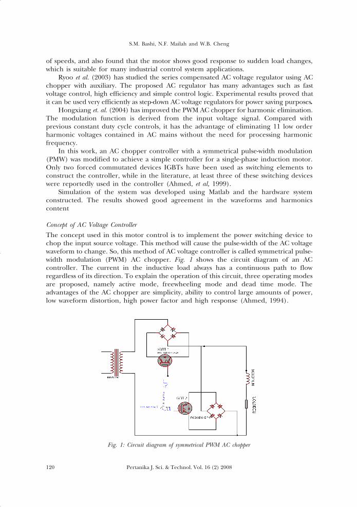
Concept of AC Voltage ControllerThe concept used in this motor control is to implement the power switching device tochop the input source voltage. This method will cause the pulse-width of the AC voltagewaveform to change. So, this method of AC voltage controller is called symmetrical pulse-width modulation (PWM) AC chopper. Fig. 1 shows the circuit diagram of an ACcontroller. The current in the inductive load always has a continuous path to flowregardless of its direction. To explain the operation of this circuit, three operating modesare proposed, namely active mode, freewheeling mode and dead time mode. Theadvantages of the AC chopper are simplicity, ability to control large amounts of power,low waveform distortion, high power factor and high response (Ahmed, 1994).
Fig. 1: Circuit diagram of symmetrical PWM AC chopper
04. jst30/2008 1/21/09, 16:51120
121Pertanika J. Sci. & Technol. Vol. 16 (2) 2008
Development of a Single-Phase PWM AC Controller
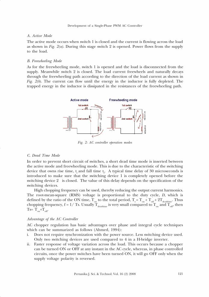
A. Active ModeThe active mode occurs when switch 1 is closed and the current is flowing across the loadas shown in Fig. 2(a). During this stage switch 2 is opened. Power flows from the supplyto the load.
B. Freewheeling ModeAs for the freewheeling mode, switch 1 is opened and the load is disconnected from thesupply. Meanwhile switch 2 is closed. The load current freewheels and naturally decaysthrough the freewheeling path according to the direction of the load current as shown inFig. 2(b). The current can flow until the energy in the inductor is fully depleted. Thetrapped energy in the inductor is dissipated in the resistances of the freewheeling path.
Fig. 2: AC controller operation modes
C. Dead Time ModeIn order to prevent short circuit of switches, a short dead time mode is inserted betweenthe active mode and freewheeling mode. This is due to the characteristic of the switchingdevice that owns rise time, tr and fall time tf. A typical time delay of 30 microseconds isintroduced to make sure that the switching device 1 is completely opened before theswitching device 2 is closed. The value of this delay depends on the specification of theswitching devices.
High chopping frequency can be used, thereby reducing the output current harmonics.The root-mean-square (RMS) voltage is proportional to the duty cycle, D, which isdefined by the ratio of the ON time, Ton to the total period, Ts = Ton + Toff + 2Tdeadtime. Thuschopping frequency, f = 1/ Ts. Usually Tdeadtime is very small compared to Ton and Toff, thenTs= Ton+Toff.
Advantage of the AC ControllerAC chopper regulation has basic advantages over phase and integral cycle techniqueswhich can be summarized as follows (Ahmed, 1994):i. Does not require synchronization with the power source. Less switching device used.
Only two switching devices are used compared to 4 in a H-bridge inverter.ii. Faster response of voltage variation across the load. This occurs because a chopper
can be turned ON or OFF at any instant in the AC cycle, whereas, in phase controlledcircuits, once the power switches have been turned ON, it will go OFF only when thesupply voltage polarity is reversed.
04. jst30/2008 1/21/09, 16:51121
S.M. Bashi, N.F. Mailah and W.B. Cheng
Pertanika J. Sci. & Technol. Vol. 16 (2) 2008122
iii. The overall power factor in the chopper regulator is higher than other topologies.iv. Although the output voltage is PWM modulated sinusoidal, the impact of the
harmonics at high frequency is minimal. Output voltage can be smoothed by simplecapacitive filter.
MATERIALS AND METHODSMatlab software has been used to simulate the AC controller circuit, and a hardwaremodel has been designed and constructed. The load and component ratings chosen forpower circuit in this work were about 10A and 240V. The main components used are asfollows:-i. IGBT (insulated gate bipolar transistor)
The IGBT chosen is IRGB10B60KDPbF with VCES = 600V and Ic = 12A. The rise time(29ns) and fall time (32ns) is also very fast, so it is excellent for fast switchingoperations.
ii. RectifierThe bridge rectifier which consists of a power diode is implemented. The bridgerectifier provides the DC voltage to IGBT because current can only flow throughIGBT in one direction.
iii. MicrocontrollerThe microcontroller chosen for this project was an 8-bit PIC16F873 microcontrollerwhich has high speed technology, low power consumption, wide operating voltagerange and fully static design.
iv. Gate DriveTo provide voltage isolation and floating points required to operate the IGBTs,single channel gate IR2117 drives have been used. There are a number of ways inwhich the gate to source, Vgs floating supply can be generated, one of these beingthe bootstrap method. The duty cycle and on-time are limited by the requirement torefresh the charge in the bootstrap capacitor (long on-times and high duty cyclesrequire a charge pump circuit). This means that the output IR2117 has to be off fora short time enough to charge the bootstrap capacitor.
v. Freewheeling diodeA “freewheeling diode” is put into a circuit to protect the switching device frombeing damaged by the reverse current of an inductive load. Without the “freewheelingdiode”, the voltage can go high enough to damage the switching devices.
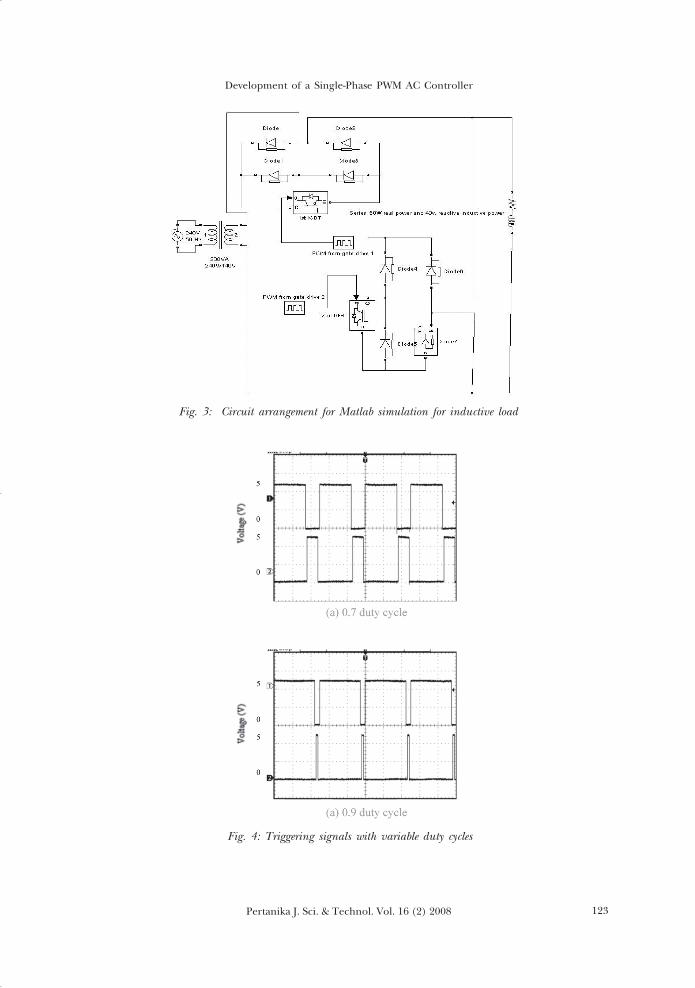
RESULTS AND DISCUSSIONTo verify the performance of the proposed symmetrical PWM AC chopper, an experimentalmodel was constructed, and a software simulation of the system developed using Matlab.Fig. 3 shows the circuit used in Matlab simulation. The circuit consists of a transformer,diodes, IGBTs and pulse generator. Inductive load has been used to represent theinduction motor at study state.
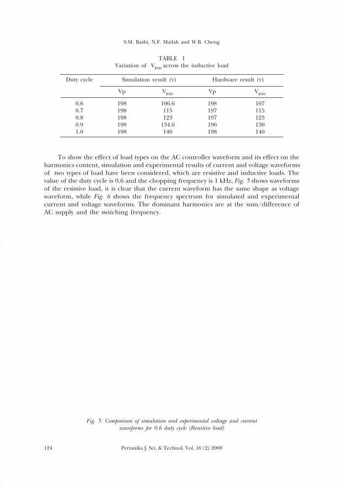
A microcontroller program has been written in C language which can providerequired signals with variable duty cycles, as shown in Fig. 4. Both models have beentested with different types of load (resistive and inductive) and different values of dutycycle. In general close agreement has been found in the simulated and experimentalresults. Table 1 shows the simulation and practical measurements, and the variation ofeffective voltage VRMS when the duty cycle changes.
04. jst30/2008 1/21/09, 16:51122
123Pertanika J. Sci. & Technol. Vol. 16 (2) 2008
Development of a Single-Phase PWM AC Controller
Fig. 3: Circuit arrangement for Matlab simulation for inductive load
Fig. 4: Triggering signals with variable duty cycles
04. jst30/2008 1/21/09, 16:51123
S.M. Bashi, N.F. Mailah and W.B. Cheng
Pertanika J. Sci. & Technol. Vol. 16 (2) 2008124
To show the effect of load types on the AC controller waveform and its effect on theharmonics content, simulation and experimental results of current and voltage waveformsof two types of load have been considered, which are resistive and inductive loads. Thevalue of the duty cycle is 0.6 and the chopping frequency is 1 kHz, Fig. 5 shows waveformsof the resistive load, it is clear that the current waveform has the same shape as voltagewaveform, while Fig. 6 shows the frequency spectrum for simulated and experimentalcurrent and voltage waveforms. The dominant harmonics are at the sum/difference ofAC supply and the switching frequency.
TABLE 1Variation of VRMS across the inductive load
Duty cycle Simulation result (v) Hardware result (v)
Vp VRMS Vp VRMS
0.6 198 106.6 198 1070.7 198 115 197 1150.8 198 123 197 1230.9 198 134.6 196 1301.0 198 140 198 140
Fig. 5: Comparison of simulation and experimental voltage and currentwaveforms for 0.6 duty cycle (Resistive load)
04. jst30/2008 1/21/09, 16:51124

125Pertanika J. Sci. & Technol. Vol. 16 (2) 2008
Development of a Single-Phase PWM AC Controller
K= fc / fs , where fc is carrier frequency (1000Hz) and fs is the supply frequency (50Hz).The order of the high harmonic content can be found as:
Harmonic order = nK ±1, where, n=1,2,3,……
So, the high harmonic contents of the voltage and current can be found in order of19, 21, 39, 40, 59 and 61. Also this can be proven by comparing with harmonic spectraas in Fig. 7. The Total Harmonic Distortion, THD of the simulated current waveform wasfound to be equal to 48% and the experimental was 51%, without any filter.
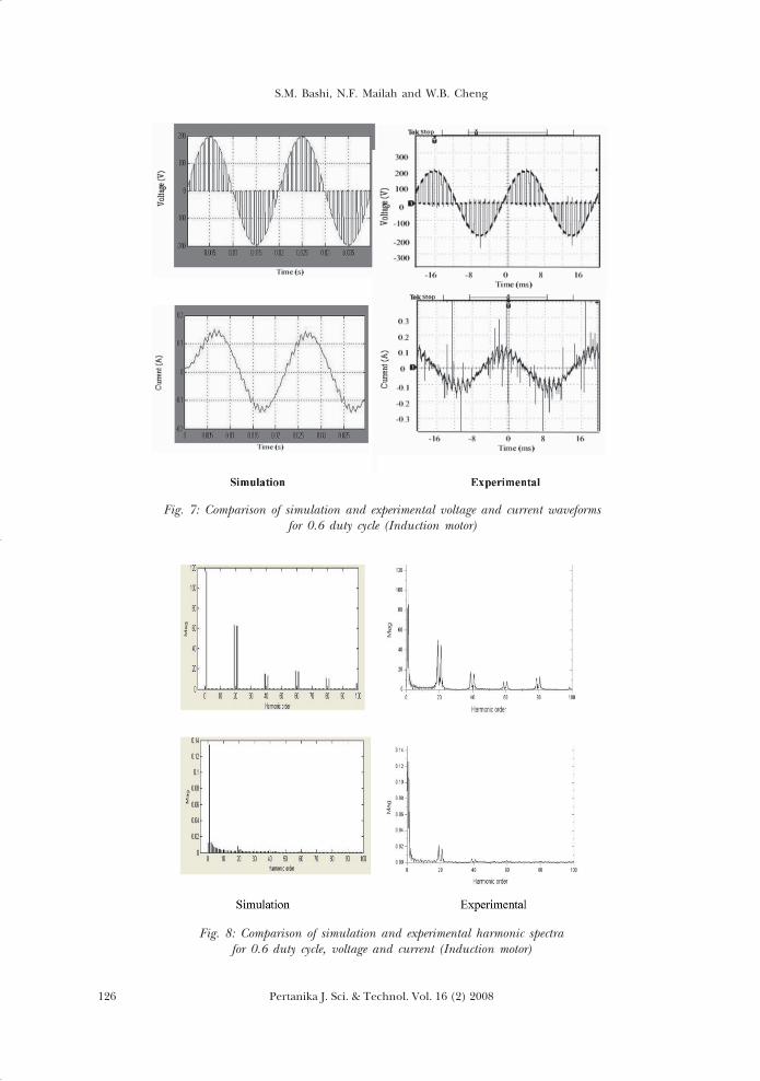
Similar measurements have been carried out for inductive loads represented by smallmotors. In Fig. 8 and due to presence of inductance, the shape of the current and voltagewaveforms are not the same. Further, there is a difference in the simulated andexperimental current waveforms and this is due to the dynamic parameters of the motor.The harmonics analysis shows that the harmonic order are the same but the amplitudeof the current harmonics are smaller due to presence of the inductance. It is clear thatthe THD of the current waveform has lower values compared with resistive loads whichshowed 17% for simulation and 21% for the experimental waveform.
Fig. 6: Comparison of simulation and experimental harmonic spectrafor 0.6 duty cycle, voltage and current (Resistive load)
Simulation Experimental
04. jst30/2008 1/21/09, 16:51125
S.M. Bashi, N.F. Mailah and W.B. Cheng
Pertanika J. Sci. & Technol. Vol. 16 (2) 2008126
Fig. 7: Comparison of simulation and experimental voltage and current waveformsfor 0.6 duty cycle (Induction motor)
Fig. 8: Comparison of simulation and experimental harmonic spectrafor 0.6 duty cycle, voltage and current (Induction motor)
04. jst30/2008 1/21/09, 16:52126

127Pertanika J. Sci. & Technol. Vol. 16 (2) 2008
Development of a Single-Phase PWM AC Controller
CONCLUSIONSA software simulation was developed for a simple AC controller and a hardware systemconstructed. Good agreement was achieved between the simulation and experimentalresults. The amount of voltage supply across the motor can be changed by varying thePWM signal of the symmetrical PWM AC chopper. This was done with the aid of aPIC16F873 microcontroller. In general, the performance of the symmetrical PWM ACchopper was good. The high order of harmonic content can be eliminated easily by asmall LC passive filter. Therefore, this method can replace the convention phase-anglecontrol line-commutated voltage controllers and integral-cycle control.
REFERENCESAHMED F.I., ZAKI A.M. and ALI E. (1994). Terminal-impedance control for energy saving in
induction motor at no and partial loads using microprocessor. Power Electronics and Variable-Speed Drives, 5th International Conference (pp. 336-341).
AHMED, N.A., AMEI, K. and SAKUI, M. (1999). A new configuration of single-phase symmetrical pwmac chopper voltage controller. IEEE Transactions on Industrial Electronics (pp. 942 – 952).
BODUR, H., BAKAN, A. F. and SARUL, M. H. (2000). Universal motor speed control with currentcontrolled pwm - ac chopper by using a microcontroller. Proceedings of IEEE InternationalConference Industrial Technology (pp. 394-398).
GUILLEMIN, P. (1996). Fuzzy logic applied to motor control. IEEE Transactions Industry Applications(pp. 51-56).
HONGXIANG Y., MIN L. and YANCHAO J. (2004). An advanced harmonic elimination PWM techniquefor AC choppers. 35th Annual IEEE Power Electronics Specialist Conference (pp. 161-165).
KWON B.H., B. MIN D. and KIM J.H. (1999). Novel topologies of AC choppers. IEE ProceedingsElectrical Power Application (pp. 323-330).
RYOO H. J., KIM J.S., RIM G.H. and KIM D.S. (2003). A study on the series compensated AC voltageregulator using AC chopper with auxiliary transformer. Industrial Electronics Society, IECON ’03,The 29th Annual Conference of the IEEE2003 (pp. 2628- 2633).
04. jst30/2008 1/21/09, 16:52127