Learning Mechanical Motion Therapy Training-Dr Maurice Pisciottano-Canonsburg PA

Journal of Healthcare Engineering · Vol. 3 · No. 3 · 2012 Page 455–476 455
Development of a Laminar Flow Bioreactor byComputational Fluid Dynamics
Meir Israelowitz1§, Birgit Weyand2§, Syed Rizvi1, Peter M. Vogt2,Herbert P. von Schroeder1,3,4,5*
1Biomimetics Technologies, Toronto, Ontario, Canada2Department of Plastic, Hand and Reconstructive Surgery, Hannover Medical School,
Hannover, Germany3Bone Lab, Faculty of Dentistry, University of Toronto, Toronto, Ontario, Canada4University Hand Program, University Health Network, Toronto, Ontario, Canada
5Department of Surgery, University of Toronto, Ontario, Canada
Submitted February 2011. Accepted for publication May 2012.
ABSTRACTThe purpose of this study is to improve the design of a bioreactor for growing bone and other three-dimensional tissues using a computational fluid dynamics (CFD) software to simulate flow througha porous scaffold, and to recommend design changes based on the results. Basic requirements forCFD modeling were that the flow in the reactor should be laminar and any flow stagnation shouldbe avoided in order to support cellular growth within the scaffold. We simulated three differentdesigns with different permeability values of the scaffold and tissue. Model simulation addressedflow patterns in combination with pressure distribution within the bioreactor. Pressure build-up andturbulent flow within the reactor was solved by introduction of an integrated bypass system forpressure release. The use of CFD afforded direct feedback to optimize the bioreactor design.
Keywords: bioreactor, laminar flow, computer graphic mesh, fluid flow simulations,computational fluid dynamics
1. INTRODUCTIONA bioreactor supports a biologically active environment for growing and expandingcells in a culture medium [1]. It can support three-dimensional tissue cultivation andspecific cell differentiation by controlled external forces and stresses [2]. However,design limitations have resulted in undesirable fluid-induced shear forces or stagnationof fluid medium causing high mortality of cells and tissues, especially in perfusionbioreactors [3, 4].
*Corresponding Author: Herb von Schroeder, Toronto Western Hospital, 399 Bathurst Street, HandClinic 2 East, Toronto, On M5T 2S8 Canada. Phone: (416) 603-5641. Fax: (416) 603-5813. E-mail:[email protected]. Other authors: [email protected]; [email protected]; [email protected]; [email protected]. §Authors contributedequally.

456 Development of a Laminar Flow Bioreactor by Computational Fluid Dynamics
In order to prevent cell death, some bioreactors have been proposed based onrotational designs to mimic a micro-gravity environment including a membraneexchange unit for metabolites and gases [5]. The rotational bioreactor design wasinitially developed by NASA [6, 7]. Such rotational models have been shown to reducethe hydrodynamic shear by approximately 10-fold [8]. Low shear is important tomaintain cell viability and tissue structure. Another example of a rotational bioreactorthat includes design properties to increase mass transfer and support large aggregates ofcells is the laminar Taylor vortex that maintains oxygenation for long-term cell culture[9]. However, a limitation with this design is that the tissue size cannot be adequatelycontrolled and the growth of large amount of cells in the scaffold remains a challenge[10, 11]. Other bioreactor designs incorporated medium stirring or cell suspensionmethodologies such as microcarrier-based cultures [5, 12, 13].
The impact of shear forces on mammalian cell’s growth and function due to theirlack of stable cell walls compared to plant cells has been noted since early advances inmammalian cell culture in the late 1980s, leading to the use of bioreactors in order toenhance cell expansion and to improve culture conditions [14, 15]. Experimentalstudies on suspension-adapted mammalian cells found turbulent shear more damagingto cells than laminar shear of the same magnitude [16, 17]. Results from studies of shearimpact on adherent mammalian cells in 2D and 3D culture demonstrated multipleinfluences on cell proliferation, cell attachment and cell differentiation [17, 18, 19].Since responses differ among cell types and sources as well as variable culture andstress conditions, there is a need particularly for well-defined 3D culture systems forcomparison of standardized cell culture [20].
Bioreactor designs are different between industrial and laboratory small-scaleapplications. The latter designs are commonly for research purposes, but cannot betransferred to industrial scale for the growth of clinically useful amount of tissues, sinceincreasing the sizes of these types of bioreactors results in detrimentally large shear forces[4, 21, 22]. An example of industrial scale bioreactors is the Air Lift Bioreactor [23] whichis a low energy input, high-yield alternative to stirred tank bioreactors that manages toachieve good oxygen transfer with low fluid shear [24, 25]. A limitation of the Air LiftBioreactor is the mixing of mass transfer and oxygen availability limiting cell growth [26],and not allowing cultivation for high cell density required for practical application [27].
It is the objective of this work to define and improve the physical environment of abioreactor using a computational fluid dynamics (CFD) model that would allow forscaling-up from research size to industrial size, improving efficiency and increasing celldensity in a controlled flow environment. This study focuses on flow perfusion bioreactorsthat allow for the design including features such as variable (‘tided’) flow, control of theflow through regions of least resistance and maintaining the flow through the scaffold [28].
2. METHODS2.1. Geometrical Model & Mesh ModelBioreactor models were sketched using Pro/Engineering 2000i (PTC, Needham,Massachusetts, USA). With Pro/Engineering, sketching in three dimensions was usefulfor progressive design modifications, and the sketches were compatible with the mesh

used for flow simulations. The three designs considered in this study included astandard reactor with a double-bell-shape vessel (design 1, see Figure 1), a pipe with acylindrical vessel (design 2, see Figure 4), and a standard reactor with internal irises(design 3, see Figure 7A and 7B).
The mesh of the bioreactor model was prepared using GAMBIT (ANSYS, Inc.,Canonsburg, Pennsylvania, USA). A cross-section of the model was composed of35000 (design 1), 65000 (design 2) and 80000 tetrahedral elements (design 3),respectively. For design 3, the porous region as well as the irises required a smallermesh of 1.27 × 10⁻³ m when the flow path becomes very narrow (Figure 7A and 7B).The larger areas of fluid flow were meshed by 5.98 × 10⁻³ m. After transfer of the meshinto the CFD modeling software (FLUENT software, ANSYS, Inc. Canonsburg,Pennsylvania, USA), the grid was checked and scaled in inches.
2.2. Scaffold PropertiesThe scaffold was simulated with a uniform porous medium model. The scaffoldporosity was set within the range of 70–90% since the porosity for bone tissue isapproximately 78% [29]. In order to mimic various stages of cell proliferation withinthe porous scaffold, 5 different permeability values representing different stages of cellgrowth were chosen according to the literature [30, 31, 32]. Scaffold thickness was setat 1 cm prior to scaling. Parameters for modeling of flow through porous media aresummarized in Table 1. The mean particle diameter Dp is determined from the Ergunequation (eqn. 5) below.
2.3. CFD Simulation & Boundary ConditionsCFD modeling was performed using FLUENT software (ANSYS, Inc. Canonsburg,Pennsylvania, USA). A CFD simulation with the following parameters and boundaryconditions was performed: axisymmetric model, segregated solver, laminar fluid flow,incompressible Newtonian fluid with the viscosity of water at 37°C (the cell culturemedium has similar physical properties as water), no-slip boundary conditions on walls,atmospheric operating pressure and reference pressure location [0, 0]. The inlet of thebioreactor was set in terms of either mass flow rate or velocity. For calculation of massflow rate in kg s-1, the components of flow directions were set as [0, -1]. For flow
Journal of Healthcare Engineering · Vol. 3 · No. 3 · 2012 457
Table 1. Scaffold parameters for CFD simulation
Viscous resistance Inertial resistance Permeability, Porosity, coefficient, coefficient, Particle diameter, κ, m2 ε 1/κ, 1/m2 C2, 1/m Dp, m
4.5200 × 10⁻¹³ 8.0000 × 10⁻¹ 2.2124 × 10¹² 5.9404 × 10⁵ 2.3015 × 10⁻⁶
5.0000 × 10⁻¹² 8.0000 × 10⁻¹ 2.0000 × 10¹¹ 1.7861 × 10⁵ 7.6547 × 10⁻⁶
5.0000 × 10⁻¹¹ 8.0000 × 10⁻¹ 2.0000 × 10¹⁰ 5.6481 × 10⁴ 2.4206 × 10⁻⁵
5.0000 × 10⁻¹⁰ 8.0000 × 10⁻¹ 2.0000 × 10⁹ 1.7861 × 10⁴ 7.6547 × 10⁻⁵
5.0000 × 10⁻⁹ 8.0000 × 10⁻¹ 2.0000 × 10⁸ 5.6481 × 10³ 2.4206 × 10⁻⁴

velocity simulations, the inlet velocity was set at 7.34 × 10⁻⁵ m s−1 [33]. Theconvergence criterion was set at 0.001 for continuity, x-velocity and y-velocity. Thenumber of iterations was set at 500 and if there was no convergence, factors for pressureand momentum were adjusted until the solution converged. Plots of flow velocity,pressure, velocity vectors and flow path lines were generated for the fluid analysis.
2.4. Flow CharacterizationLaminar flow is determined by the Reynolds number. When fluid moves smoothly inparallel layers and the Reynolds number is lower than the critical value of 2000, theflow is assumed to be laminar, whereas for Reynolds numbers above 3000, the flow isconsidered to be turbulent [34]. The Reynolds number is calculated as
(1)
where V is the average flow velocity, d is the diameter of the bioreactor and ν is thekinematic viscosity of water with ν = 10−6m2 s−1 = 1 cSt at 20°C [35]. The average flowvelocity V is obtained from
(2)
where Q is the volumetric flow rate and A is the cross-sectional flow area with
(3)
For laminar flow of viscous fluids, the velocity increases towards the center of thescaffold and is a function of the radial location. The velocity is also inverselyproportional to the viscosity of the fluid [36]. The viscosity and permeability for thesimulation are related by Darcy’s Law [18, 36, 37]:
(4)
where κ is the hydrodynamic permeability, µ is the dynamic viscosity (considered to bethe same as water at 20°C with 0.001 Pa s), ∆P is the pressure drop across the porousscaffold, and L is the thickness of the scaffold.
The Ergun equation below can be applied to calculate the pressure drop across aporous medium (packed bed model) by linearly combining the Blake-Kozeny model forlaminar flow with the Burke-Plummer model for turbulent flow (the first and secondterms on the right side of eqn. 5, respectively) [38, 39]:
(5)∆P
L
V
D
V
Dp p
= −( ) + × −( )150 11 75
12
2 3
2
3µ ε
εε ρ
ε.
Q
A
P
L=
×
κµ
∆
A d= ×π 2
4
Q V A= ×
Re = ×V dν
458 Development of a Laminar Flow Bioreactor by Computational Fluid Dynamics

where ε is the porosity of the scaffold, ρ is the density of the fluid and Dp is the meanparticle diameter of the porous medium [39]. Related to this equation, the viscousresistance coefficient 1/κ (which dominates at low Re) and the inertial resistancecoefficient C2 (which dominates at high Re) can be derived as follows [40]:
(6)
(7)
2.5. Prototype testing and cell culture conditionsHuman adipose mesenchymal stem cells were derived from fat tissue of donorsundergoing abdominoplasty after obtaining approval from the Research EthicsCommittee and informed consent from the patients. Briefly, cells were isolated bycollagenase digestion and sequential centrifugation according to standard protocols[41]. Adipose mesenchymal stem cells were expanded in standard culture medium(DMEM-F12 (PAA laboratories, US), 5% FCS, supplemented with antibiotics,sodium pyuvate and non-essential amino-acids (all Biochrom, US)) and then seededonto macroporous ceramic scaffolds (Sponceram® Zellwerk GmbH, Germany).Scaffolds were cultured under static conditions in a Petri dish inside a cell cultureincubator at 37°C, 5% CO2, and under dynamic condition within the bioreactorprototype with continuous perfusion of 1 ml/min via a peristaltic pump (Ismatec,Germany) at 37°C for 1 month in standard culture medium with HEPES buffersolution at 0.01M (PAA Laboratories, US). Scaffold were stained with fluoresceindiacetate 2,4 µmolL−1 (Sigma, Germany), washed with phosphate buffer saline(PAA laboratories, US) and cell vitality was analysed via stereomicroscopy(Olympus SZX16).
3. RESULTS3.1. Design 1The primary design was based on a standard perfusion bioreactor [42]. The mesh modelby GAMBIT is presented in Figure 1.
Flow simulations by FLUENT revealed significant problems with flow stagnationas well as relevant pressure build-up upstream of the reactor as demonstrated inFigure 2A and B. There was a significant decrease in flow velocity across thescaffold, which might adversely affect mass transport and oxygen transfer to thecells in the scaffold.
Figure 3 shows the distribution of flow vectors which are not parallel (laminar)downstream of the scaffold. These results suggest that this design of the bioreactorneeds to be improved in order to reduce flow stagnation and irregularities.
CDp
2 33 5 1= −( )
×. ε
ε
1 150 1 2
2 3κε
ε= −( )
×Dp
Journal of Healthcare Engineering · Vol. 3 · No. 3 · 2012 459

460 Development of a Laminar Flow Bioreactor by Computational Fluid Dynamics
1A
1B
1C
Figure 1. Mesh of bioreactor design 1. 1A: flow inlet. 1B: scaffold. 1C: flow outlet.
2.68e−07
2.41e−07
2.14e−07
Scaffold
1.88e−07
1.61e−07
1.34e−07
1.07e−07
8.04e−08
5.36e−08
2.68e−08
0.00e+00
Figure 2A. Flow path lines of bioreactor design 1 show significant stagnation aboveand below scaffold level (velocity values in m s−1; e-08 = × 10−8).

Journal of Healthcare Engineering · Vol. 3 · No. 3 · 2012 461
6.04e−02
5.44e−02
4.83e−02
4.23e−02
3.62e−02
3.02e−02
2.42e−02
1.81e−02
1.21e−02
6.04e−03
0.00e+00
2.71e−07
2.44e−07
2.17e−07
1.90e−07
1.63e−07
1.36e−07
1.09e−07
8.14e−07
5.43e−08
2.71e−08
1.82e−13
Figure 2B. Pressure distribution of bioreactor design 1 reveals significant pressurebuild-up upstream of scaffold (pressure values in Pa; e-02 = × 10−2).
Figure 3. Flow vectors of bioreactor design 1 show irregular currents downstream ofscaffold, suggesting turbulence (velocity values in m s−1; e-08 = × 10−8).

462 Development of a Laminar Flow Bioreactor by Computational Fluid Dynamics
Figure 4. Mesh of bioreactor design 2. 4A: flow inlet. 4B: scaffold position. 4C:flow outlet.
3.2. Design 2Based on the CFD results of design 1, the geometry of the bioreactor was modified toresemble a pipe in order to optimize flow patterns. Figure 4 shows the GAMBIT meshof bioreactor design 2.
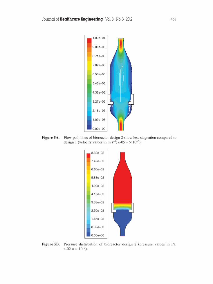
Results of flow simulation by FLUENT software are presented in Figures 5 and 6,demonstrating flow path lines more regular with less stagnation (Figure 5A) but therewas still a significant pressure build-up in the upper half of the vessel (Figure 5B). Flowvectors are more regular and parallel to each other, suggesting laminar flow pattern,than in design 1, as shown in Figure 6.
3.3. Design 3Deficiency of both of the previous designs led to the introduction of a third design.From the simulation results of those designs, we learned that a bypass system wouldbe conducive to releasing pressure build-up in the system and preventing flowirregularities. Therefore, irises were introduced to our design 3 in order to control theflow and pressure in the bioreactor [43, 44]. The iris system opens and closes like theiris of eye, and can be controlled by pressure sensors installed upstream anddownstream of the scaffold in the bioreactor. Although the openings of these iriseswere adjustable, they were set as completely closed or completely open in oursimulation. Figure 7 demonstrates the mesh for design 3 using GAMBIT solidgeometry Modeler and GAMBIT mesh modeler given the flow domain. Figure 7Ashows the design with closed irises, where the main flow field was meshed with amesh size of 5.98 × 10⁻³ m. In order to model the design with open irises as shown in
Journal of Healthcare Engineering · Vol. 3 · No. 3 · 2012 463
1.09e−04
9.80e−05
8.71e−05
7.62e−05
6.53e−05
5.45e−05
4.36e−05
3.27e−05
2.18e−05
1.09e−05
0.00e+00
Figure 5A. Flow path lines of bioreactor design 2 show less stagnation compared todesign 1 (velocity values in m s−1; e-05 = × 10−5).
8.32e−02
7.49e−02
6.66e−02
5.83e−02
4.99e−02
4.16e−02
3.33e−02
2.50e−02
1.66e−02
8.32e−03
0.00e+00
Figure 5B. Pressure distribution of bioreactor design 2 (pressure values in Pa;e-02 = × 10−2).

Figure 7B, a finer mesh size of 1.27 × 10⁻³ m was adopted since the open flow pathbecame very narrow.
CFD simulations of design 3 exemplary for some scaffold permeability values(Table 1) are exhibited in Figure 8 (flow path lines) and Figure 9 (pressure drop acrossscaffold) for closed irises, as well as in Figure 10 (flow path lines) and Figure 11(pressure drop across scaffold) for open irises.
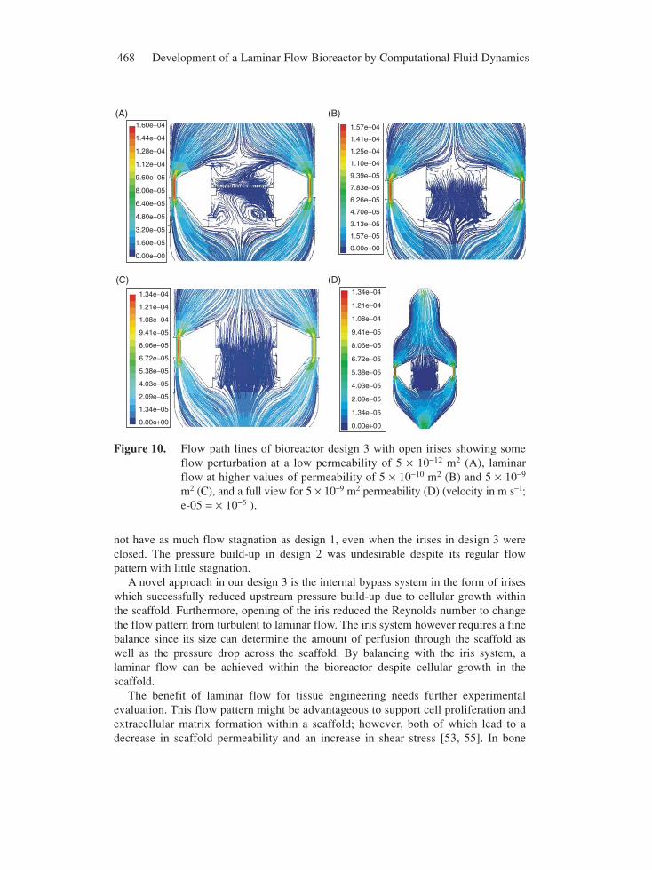
When irises were closed, fluid flow did not converge for the lowest permeability 4.5 ×10⁻¹³ m2 and 5 × 10⁻¹² m2, and even with open irises, there were some flowirregularities for these values of permeability (Figure 10 A). However, at higher valuesof permeability, there was laminar flow at scaffold level when irises were open (Figure10 B – D). Opening of the iris system significantly reduced the pressure drop acrossthe scaffold from 1.05 Pa to 2.0 × 10⁻³ Pa (Figures 9 and 11, simulated for permeabilityof 5 × 10⁻⁹ m2).
Figure 12 presents a closer view of pressure distribution at scaffold level for closed(Figure 12A) and open irises (Figure 12B). The calculated Reynolds number withclosed irises was 2942, indicating turbulence with high pressure drop and shear, whileopening of the iris reduced the Reynolds number to 641, indicating laminar flow.Table 2 summarizes results of CFD simulation for pressure distribution of the threedesigns, where opening of the iris system in design 3 allows decrease of high pressureupstream of the scaffold.
464 Development of a Laminar Flow Bioreactor by Computational Fluid Dynamics
9.84e−05
8.75e−05
7.65e−05
6.56e−05
5.47e−05
4.38e−05
3.28e−05
2.19e−05
1.10e−05
3.97e−08
1.09e−04
Figure 6. Flow vectors of bioreactor design 2 are more regular compared to design1 (velocity values in m s−1; e-05 = × 10−5).

Journal of Healthcare Engineering · Vol. 3 · No. 3 · 2012 465
7A (1)
7A (2)
7A (3)
Figure 7A. Mesh for bioreactor design 3 with a mesh size of 5.98 × 10⁻³ m for themain flow field and finer mesh size of 1.27 × 10⁻³ m at the scaffold level.7A(1): flow inlet. 7A(2): scaffold. 7A(3): flow outlet.
7B (1)
7B (2)
7B (3)
7B (4)
Figure 7B. Mesh for bioreactor design 3 with irises also meshed with a finer meshsize of 1.27 × 10⁻³ m. 7B(1): flow inlet. 7B(2): scaffold. 7B(3): irissystem. 7B(4): flow outlet.

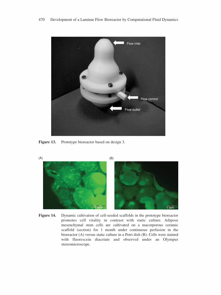
Based on results of the CFD modeling, a prototype reactor was built as shown inFigure 13. Results of biological experiments with human adipose mesenchymal stem cellscultured in a macroporous ceramic scaffold demonstrated constant high cellular viabilityafter 1 month of dynamic culture within the bioreactors, as shown in Figure 14A, incontrast to static culture in the Petri dish (Fig 14B).
466 Development of a Laminar Flow Bioreactor by Computational Fluid Dynamics
7.69e−05
6.93e−05
6.16e−05
6.39e−05
4.62e−05
3.85e−05
3.08e−05
2.31e−05
1.54e−05
7.69e−06
0.00e+00
7.69e−05
6.93e−05
6.16e−05
6.39e−05
4.62e−05
3.85e−05
3.08e−05
2.31e−05
1.54e−05
7.69e−06
0.00e+00
(A)
(B)
Figure 8. Flow path lines of bioreactor design 3 with closed irises showing somestagnation at scaffold level (A) and full view (B) (velocity in m s−1; e-05= × 10−5, permeability = 5 × 10⁻⁹ m2).

Journal of Healthcare Engineering · Vol. 3 · No. 3 · 2012 467
Figure 9. Pressure variation across the scaffold in bioreactor design 3 showingpressure drop of 1.05 Pa at the scaffold for permeability 5 × 10⁻⁹ m2
(inlet location −0.35 m, scaffold location −0.225 m, outlet location −0.125 m).
4. DISCUSSIONDifferent perfusion bioreactors have been developed for tissue engineeringapplications, especially for bone tissue engineering [28, 45, 46]. However, manysystems were characterized only by perfusion rate and lack substantial informationabout shear stress within the reactor vessel [47]. The results of our study suggest thatreactor geometry has a significant impact on flow perfusion and pressure distributionaround the scaffold. Common designs such as bell-shaped and cylindrical vesselscannot guarantee continuous perfusion across scaffolds without creating areas of flowstagnation or pressure build-up, as demonstrated in our CFD simulation results.Furthermore, our results show that increase in permeability of the scaffold due tocellular growth has an impact on flow vectors and pressure distribution.
In our approach, we focused on modeling of flow path lines within a reactor vesseland across the scaffold with different values of permeability due to cellular growth.However, we did not study the shear stress within the scaffold itself. For this issue, theinterconnectivity and tortuosity of scaffold pores as well as cellular growth within thepores need to be considered [48]. Calculations will require precisely defined scaffoldgeometry through, e.g., CT scanning, and infinite elements analysis tools [49, 50].Recent studies on CFD modeling have been performed on modeling fluid flow throughregular and irregular scaffolds during perfusion without considering reactor shape[51, 52, 53, 54].
From the analysis of the different designs, it was apparent that optimizing thegeometry of the reactor was necessary to reduce flow irregularities. Designs 2 and 3 did
468 Development of a Laminar Flow Bioreactor by Computational Fluid Dynamics
not have as much flow stagnation as design 1, even when the irises in design 3 wereclosed. The pressure build-up in design 2 was undesirable despite its regular flowpattern with little stagnation.
A novel approach in our design 3 is the internal bypass system in the form of iriseswhich successfully reduced upstream pressure build-up due to cellular growth withinthe scaffold. Furthermore, opening of the iris reduced the Reynolds number to changethe flow pattern from turbulent to laminar flow. The iris system however requires a finebalance since its size can determine the amount of perfusion through the scaffold aswell as the pressure drop across the scaffold. By balancing with the iris system, alaminar flow can be achieved within the bioreactor despite cellular growth in thescaffold.
The benefit of laminar flow for tissue engineering needs further experimentalevaluation. This flow pattern might be advantageous to support cell proliferation andextracellular matrix formation within a scaffold; however, both of which lead to adecrease in scaffold permeability and an increase in shear stress [53, 55]. In bone
1.60e−04
1.44e−04
1.28e−04
1.12e−04
9.60e−05
8.00e−05
6.40e−05
4.80e−05
3.20e−05
1.60e−05
0.00e+00
1.57e−04
1.41e−04
1.25e−04
1.10e−04
9.39e−05
7.83e−05
6.26e−05
4.70e−05
3.13e−05
1.57e−05
0.00e+00
1.34e−04
1.21e−04
1.08e−04
9.41e−05
8.06e−05
6.72e−05
5.38e−05
4.03e−05
2.09e−05
1.34e−05
0.00e+00
1.34e−04
1.21e−04
1.08e−04
9.41e−05
8.06e−05
6.72e−05
5.38e−05
4.03e−05
2.09e−05
1.34e−05
0.00e+00
(A) (B)
(D)(C)
Figure 10. Flow path lines of bioreactor design 3 with open irises showing someflow perturbation at a low permeability of 5 × 10⁻¹² m2 (A), laminarflow at higher values of permeability of 5 × 10⁻¹⁰ m2 (B) and 5 × 10⁻⁹
m2 (C), and a full view for 5 × 10⁻⁹ m2 permeability (D) (velocity in m s−1;e-05 = × 10−5 ).

Journal of Healthcare Engineering · Vol. 3 · No. 3 · 2012 469
Figure 11. Pressure variation across the scaffold in bioreactor design 3 with openirises, showing significantly reduced pressure drop of 2 × 10⁻³ Pa at thescaffold for permeability of 5 × 10⁻⁹ m2 (inlet position −0.35m, scaffoldposition −0.225 m, outlet position −0.125 m).
4.93e−034.52e−034.11e−033.70e−033.29e−032.88e−032.47e−032.05e−031.64e−031.23e−038.22e−044.11e−040.00e+00
1.08e−039.87e−048.97e−048.07e−047.18e−046.28e−045.38e−044.49e−043.59e−042.69e−041.79e−048.97e−050.00e+00
(A) (B)
Figure 12. Pressure distribution of bioreactor design 3 around the scaffold withclosed (A) and open (B) irises. (Pressure in Pa; e-04 = × 10−4).
Table 2. Comparison of CFD simulation results for pressure variation across thescaffold in different designs of bioreactor
Design 3
Design 1 Design 2 Irises closed Irises open
Upstream Pressure [Pa] 6.04 × 10⁻² 8.32 × 10⁻² 4.93 × 10⁻³ 1.08 × 10⁻³
Downstream Pressure [Pa] 0 0 0 8.97 × 10⁻⁵
470 Development of a Laminar Flow Bioreactor by Computational Fluid Dynamics
Flow inlet
Flow control
Flow outlet
Figure 13. Prototype bioreactor based on design 3.
1 mm
(A) (B)
1 mm
Figure 14. Dynamic cultivation of cell-seeded scaffolds in the prototype bioreactorpromotes cell vitality in contrast with static culture. Adiposemesenchymal stem cells are cultivated on a macorporous ceramicscaffold (section) for 1 month under continuous perfusion in thebioreactor (A) versus static culture in a Petri dish (B). Cells were stainedwith fluorescein diacetate and observed under an Olympusstereomicroscope.

Journal of Healthcare Engineering · Vol. 3 · No. 3 · 2012 471
tissue engineering, osteogenic differentiation is stimulated by higher perfusion rate inperfusion bioreactors where turbulent flow patterns may occur [56]. Interestingly, theshear stress required to induce osteogenic differentiation of cells have been found tobe two to three orders of magnitude (102 to 103) higher in two-dimensional perfusionchambers than in three-dimensional cultures [57]. The results with our prototypebioreactor also demonstrate a benefit of laminar flow compared to static cultureconditions in respect to cell viability and osteogenic differentiation of adipose-derived stem cells [58]. Scaling of the model as performed in the current approachwill allow volume increase of the reactor to an industrial size without change of theinternal flow pattern.
In order to further optimize CFD prediction of the model, additional mesh refinementwould be required, for which as many square edges in the mesh as possible have to beremoved, especially in the area around the tissue and scaffold. Since our systemconsiders fluid pressure in a finite element model, the flow creates a displacementdeformation and therefore the mesh needs to minimize the square surfaces [59].
A problem with utilizing software for the CFD simulations is the limitations of thesoftware (FLUENT was employed in the present study) itself in simulating flow acrosslow-permeability media. The results could be improved with a more powerful softwarecapable of solving flow under very low permeability.
A further improvement of the bioreactor design can be achieved by three-dimensional CFD modeling to characterize the flows through the scaffold and the irises.However, a complete three-dimensional modeling of flow is very costly with respect tocomputer time or hardware, even if using open source software. Furthermore, turbulentflow needs to be analyzed by solving the Navier-Stokes equation which could be verydifficult and costly [59]. Other approaches employed Lattice Boltzmann equation whichrequires many very small increments for optimization of the turbulence [60, 61, 62]. Weare currently working on three-dimensional modeling of the bioreactor in order toresolve issues of turbulence and specify flow patterns based on scaffold properties anddimensions of the irises.
One of the major considerations for any bioreactor design is the support of cellproliferation. This also includes formation of extracellular matrix as a provider forcellular three-dimensional arrangement. The Reynolds number in the reactor affects cellproliferation and extracellular matrix formation. Studies are still needed to examine theeffect of physical stresses on cellular behaviour, cell growth, extracellular matrixformation and cell differentiation which depends on the cell type. Further interestingissues are how cells sense changes in the extracellular environment, and how changesin the extracellular matrix content and composition change cell physiology (e.g., duringthe mineralization process of bone callus tissue in fracture healing). Three-dimensionalcell culture differs significantly from the standard two-dimensional cell culture in aPetri dish where overcrowding often leads to cell growth arrest and cell death [63, 64,65]. The biological complexity always needs to be considered for optimal in vitro 2Dand 3D cell culture. With well-characterized bioreactor systems for tissue engineering,we may achieve a better understanding for the essential factors and stimuli for tissueformation, growth and remodeling.

472 Development of a Laminar Flow Bioreactor by Computational Fluid Dynamics
5. CONCLUSIONDifferent perfusion bioreactor designs were analyzed by CFD software regarding flowpattern and pressure distribution around a porous scaffold with changing permeabilityrepresenting cell growth. Results demonstrated that common designs such as bell-shapedand cylindrical geometries display regions of flow stagnation and flow irregularities aswell as pressure build-up upstream of the scaffold. Laminar flow was achieved byintroducing an internal iris system acting as bypass to regulate pressure drop and flowpath lines after permeability decreased due to cellular growth within the scaffold. Usingirises to control fluid flow, we have developed a method to overcome many limitationsof flow patterns in current bioreactor systems by regulating the pressure. Theadvancement of tissue engineering will continue towards growing clinically relevanttissues for musculoskeletal reconstruction or organ replacement. This advancementrequires bioreactors of high performance. Our data demonstrate that bioreactor geometrycan have a significant impact on internal flow patterns and pressure distributions. CFDmodeling provides a useful tool to improve bioreactor design.
ACKNOWLEDGEMENTSThe authors wish to thank Dr. Ibraheem Swaish of the Institute for ComplexEngineering at Carnegie Mellon University, Pittsburgh, USA for help with the FLUENTsimulations and GAMBIT analysis and Dipl.-Math. Olaf Schmidt from the Institut fürGetriebetechnik of Gottfried Wilhelm Leibniz University of Hannover, Germany forhelp with drawings of the models used in FLUENT.
CONFLICT OF INTEREST:None.
NOMENCLATUREA cross-sectional flow area, m2
C2 inertial resistance coefficient, m−1
d diameter of bioreactor, mDp mean particle diameter, mL thickness of scaffold, mP pressure, PaQ volumetric flow rate, m3 s−1
Re Reynolds number, dimensionlessV average flow velocity, m s−1
Greekε porosity, dimensionlessκ hydrodynamic permeability, m2
1/κ viscous resistance coefficient, m−2
µ dynamic viscosity, Pa-sν kinematic viscosity, m2 s−1
ρ density of fluid, kg m−3

REFERENCES[1] Meyer U, Joos U, Wiesmann HP. Biological and biophysical principles in extracorporal bone tissue
engineering. Part I. International Journal of Oral and Maxillofacial Surgery. 2004, 33(4): 325–332.
[2] Margolis L, Hatfill S, Chuaqui R, Vocke C, Emmert-Buck M, Linehan WM, Duray PH. Long termorgan culture of human prostate tissue in a NASA-designed rotating wall bioreactor. The Journal ofUrology. 1999, 161(1): 290–297.
[3] Cartmell SH, Porter BD, Garcia AJ, Guldberg RE. Effects of medium perfusion rate on cell-seededthree-dimensional bone constructs in vitro. Tissue Engineering. 2003, 9(6): 1197–1203.
[4] Santoro R, Olivares AL, Brans G, Wirz D, Longinotti C, Lacroix D, Martin I, Wendt D. Bioreactorbased engineering of large-scale human cartilage grafts for joint resurfacing. Biomaterials. 2010,31(34): 8946–8952.
[5] Sikavitsas VI, Bancroft GN, Mikos AG. Formation of three-dimensional cell/polymer constructs forbone tissue engineering in a spinner flask and a rotating wall vessel bioreactor. Journal of BiomedicalMaterials Research. 2002, 62(1): 136–148.
[6] Dutt K, Harris-Hooker S, Ellerson D, Layne D, Kumar R, Hunt R. Generation of 3D retina-like structuresfrom a human retinal cell line in a NASA bioreactor. Cell Transplantation. 2003, 12(7): 717–731.
[7] Rucci N, Migliaccio S, Zani BM, Taranta A, Teti A. Characterization of the osteoblast-like cellphenotype under microgravity conditions in the NASA-approved Rotating Wall Vessel bioreactor(RWV). Journal of Cellular Biochemistry. 2002, 85(1): 167–179.
[8] Pollack SR, Meaney DF, Levine EM, Litt M, Johnston ED. Numerical model and experimentalvalidation of microcarrier motion in a rotating bioreactor. Tissue Engineering. 2000, 6(5): 519–530.
[9] Curran SJ, Black RA. Oxygen transport and cell viability in an annular flow bioreactor: comparisonof laminar Couette and Taylor-vortex flow regimes. Biotechnology and Bioengineering. 2005, 89(7):766–774.
[10] Botchwey EA, Pollack SR, Levine EM, Laurencin CT. Bone tissue engineering in a rotating bioreactorusing a microcarrier matrix system. Journal of Biomedical Materials Research. 2001, 55(2): 242–253.
[11] Cummings LJ, Waters SL. Tissue growth in a rotating bioreactor. Part II: fluid flow and nutrienttransport problems. Mathematical Medicine and Biology : A Journal of the IMA. 2007, 24(2):169–208.
[12] Baksh D, Zandstra PW, Davies JE. A non-contact suspension culture approach to the culture ofosteogenic cells derived from a CD49elow subpopulation of human bone marrow-derived cells.Biotechnology and Bioengineering. 2007, 98(6): 1195–1208.
[13] Bilgen B, Barabino GA. Location of scaffolds in bioreactors modulates the hydrodynamicenvironment experienced by engineered tissues. Biotechnology and Bioengineering. 2007, 98(1):282–294.
[14] Papoutsakis ET. Fluid-mechanical damage of animal cells in bioreactors. Trends in Biotechnology.1991, 9(12): 427–437.
[15] Born C, Zhang Z, Al-Rubeai M, Thomas CR. Estimation of disruption of animal cells by laminar shearstress. Biotechnology and Bioengineering. 1992, 40(9): 1004–1010.
[16] Kretzmer G, Schugerl K. Response of mammalian cells to shear stress. Applied Microbiology andBiotechnology. 1991, 34(5): 613–616.
[17] Brindley D, Moorthy K, Lee JH, Mason C, Kim HW, Wall I. Bioprocess forces and their impact oncell behavior: implications for bone regeneration therapy. Journal of Tissue Engineering. 2011, ArticleID620247: 1–13; doi:10.4061/2011/620247.
[18] Kapur S, Baylink DJ, Lau KH. Fluid flow shear stress stimulates human osteoblast proliferation anddifferentiation through multiple interacting and competing signal transduction pathways. Bone. 2003,32(3): 241–251.
[19] Frangos JA, McIntire LV, Eskin SG. Shear stress induced stimulation of mammalian cell metabolism.Biotechnology and Bioengineering. 1988, 32(8): 1053–1060.
Journal of Healthcare Engineering · Vol. 3 · No. 3 · 2012 473

[20] Rauh J, Milan F, Gunther KP, Stiehler M. Bioreactor systems for bone tissue engineering. TissueEngineering. Part B, Reviews. 2011, 17(4): 263–280.
[21] Cioffi M, Kuffer J, Strobel S, Dubini G, Martin I, Wendt D. Computational evaluation of oxygen andshear stress distributions in 3D perfusion culture systems: macro-scale and micro-structured models.Journal of Biomechanics. 2008, 41(14): 2918–2925.
[22] Kehoe DE, Jing D, Lock LT, Tzanakakis ES. Scalable stirred-suspension bioreactor culture of humanpluripotent stem cells. Tissue Engineering. Part A. 2010, 16(2): 405–421.
[23] Christi MY. Airlift Bioreactors. In: R. D. Cook (ed.). Elsevier Applied Biotechnology Series, Springer,Berlin, Heidelberg, New York, 1989: 335–345.
[24] Su WW, Arias R. Continuous plant cell perfusion culture: bioreactor characterization and secretedenzyme production. Journal of Bioscience and Bioengineering. 2003, 95(1): 13–20.
[25] Mahmoudifar N, Doran PM. Tissue engineering of human cartilage and osteochondral compositesusing recirculation bioreactors. Biomaterials. 2005, 26(34): 7012–7024.
[26] Hu W, Zhong J. Effect of bottom clearance on performance of airlift bioreactor in high-density cultureof Panax notoginseng cells. Journal of Bioscience and Bioengineering. 2001, 92(4): 389–392.
[27] Tang WL, Zhao H. Industrial biotechnology: tools and applications. Biotechnology Journal. 2009,4(12): 1725–1739.
[28] Bancroft GN, Sikavitsas VI, Mikos AG. Design of a flow perfusion bioreactor system for bone tissue-engineering applications. Tissue Engineering. 2003, 9(3): 549–554.
[29] Johnson DL, Koplik J, Schwartz LM. New pore-size parameter characterizing transport in porousmedia. Physical Review Letters. 1986, 57(20): 2564–2567.
[30] Shastri VP, Martin I, Langer R. Macroporous polymer foams by hydrocarbon templating.Proceedings of the National Academy of Sciences of the United States of America. 2000, 97(5):1970–1975.
[31] Goskonda VR, Khan MA, Hutak CM, Reddy IK. Permeability characteristics of novel mydriaticagents using an in vitro cell culture model that utilizes SIRC rabbit corneal cells. Journal ofPharmaceutical Sciences. 1999, 88(2): 180–184.
[32] Darling EM, Athanasiou KA. Articular cartilage bioreactors and bioprocesses. Tissue Engineering.2003, 9(1): 9–26.
[33] Zhang H, Williams-Dalson W, Keshavarz-Moore E, Shamlou PA. Computational-fluid-dynamics(CFD) analysis of mixing and gas-liquid mass transfer in shake flasks. Biotechnology and AppliedBiochemistry. 2005, 41(Pt 1): 1–8.
[34] Bear J. Dynamics of Fluids in Porous Media. Dover Books on Physics and Chemistry, DoverPublication, New York, 1988: 5–20.
[35] Tropea C, Yarin AL, Foss JF. Springer handbook of experimental fluid mechanics. Vol. 1, Springer,Berlin, Heidelberg, New York, 2007: 56.
[36] KL Buehler. Effect of Membrane-Support and Solvent Quality on Permeability Characteristics of ConfinedPolyacrylamide Gels. PhD Thesis, Carnegie Mellon University Pittsburgh, PA USA, 1999, 70–90.
[37] Happel J, Brenner H. Low Reynolds Number Hydrodynamics: with special application to particulatemedia. In: Mechanics of Fluids and Transport Processes, Nartinus Jijhof Publisher, Dordrecht,Netherlands, 1965, 10–200.
[38] Wu J-, Yin S-. A Micro-Mechanism Model for Porous Media. Communications in Theoretical Physics.2009, 52: 936–940.
[39] Ergun S. Fluid Flow through Packed Columns. Chemical Engineering Progress. 1952, 48(2): 89–94.
[40] Nagata S. Mixing- principle and applications, 3rd ed., John Wiley and Sons, Halstedt Press, New York,1975, 138–144.
[41] Kuhbier JW, Weyand B, Radtke C, Vogt PM, Kasper C, Reimers K. Isolation, characterization,differentiation, and application of adipose-derived stem cells. Advances in BiochemicalEngineering/Biotechnology. 2010, 123: 55–105.
474 Development of a Laminar Flow Bioreactor by Computational Fluid Dynamics

Journal of Healthcare Engineering · Vol. 3 · No. 3 · 2012 475
[42] McDuffe NG. Bioreactor Design Fundamentals, 3rd ed, Butterwood-Heinemann, Boston, 1991:10–90.
[43] Israelowitz M, Rizvi S, Holmes C, Gille C, von Schroder HP. Apparatus for culture and growth of cellsto a three-dimensional tissue, European Union Patent 200808011144.6/EP 2031501.
[44] Israelowitz M, Rizvi S, Holmes C, Gille C, von Schroder HP. Laminar Flow Bioreactor, United StatesPatent Application 20076083494/20090061508.
[45] Martin I, Wendt D, Heberer M. The role of bioreactors in tissue engineering. Trends in Biotechnology.2004, 22(2): 80–86.
[46] Grayson WL, Bhumiratana S, Cannizzaro C, Vunjak-Novakovic G. Bioreactor cultivation offunctional bone grafts. Methods in Molecular Biology. 2011, 698: 231–241.
[47] Weyand B, Israelowitz M, von Schroeder HP, Vogt PM. Fluid dynamics in bioreactor design:considerations for the theoretical and practical approach. Advances in BiochemicalEngineering/Biotechnology. 2009, 112: 251–268.
[48] Johnson DL, Koplik J, Dashen R. Theory of dynamic permeability and tortuosity in fluid-saturatedporous media. Journal of Fluid Mechanics. 1987, 176: 379–420.
[49] Voronov R, Vangordon S, Sikavitsas VI, Papavassiliou DV. Computational modeling of flow-inducedshear stresses within 3D salt-leached porous scaffolds imaged via micro-CT. Journal of Biomechanics.2010, 43(7): 1279–1286.
[50] Cioffi M, Boschetti F, Raimondi MT, Dubini G. Modeling evaluation of the fluid-dynamicmicroenvironment in tissue-engineered constructs: a micro-CT based model. Biotechnology andBioengineering. 2006, 93(3): 500–510.
[51] Porter B, Zauel R, Stockman H, Guldberg R, Fyhrie D. 3-D computational modeling of media flowthrough scaffolds in a perfusion bioreactor. Journal of Biomechanics. 2005, 38(3): 543–549.
[52] Zhao F, Chella R, Ma T. Effects of shear stress on 3-D human mesenchymal stem cell constructdevelopment in a perfusion bioreactor system: Experiments and hydrodynamic modeling.Biotechnology and Bioengineering. 2007, 96(3): 584–595.
[53] Vossenberg P, Higuera GA, van Straten G, van Blitterswijk CA, van Boxtel AJ. Darcian permeabilityconstant as indicator for shear stresses in regular scaffold systems for tissue engineering.Biomechanics and Modeling in Mechanobiology. 2009, 8(6): 499–507.
[54] Sandino C, Planell JA, Lacroix D. A finite element study of mechanical stimuli in scaffolds for bonetissue engineering. Journal of Biomechanics. 2008, 41(5): 1005–1014.
[55] Martin Y, Vermette P. Bioreactors for tissue mass culture: design, characterization, and recentadvances. Biomaterials. 2005, 26(35): 7481–7503.
[56] Sikavitsas VI, Bancroft GN, Holtorf HL, Jansen JA, Mikos AG. Mineralized matrix deposition bymarrow stromal osteoblasts in 3D perfusion culture increases with increasing fluid shear forces.Proceedings of the National Academy of Sciences of the United States of America. 2003, 100(25):14683–14688.
[57] McCoy RJ, O’Brien FJ. Influence of shear stress in perfusion bioreactor cultures for the developmentof three-dimensional bone tissue constructs: a review. Tissue Engineering. Part B, Reviews. 2010,16(6): 587–601.
[58] Weyand B, Reimers K. Vogt PM, Influences of extracellular matrix properties and flow shear stresses onstem cell shape in a three-dimensional dynamic environment. Conf Proc IFMBE Proc. 2011, 30: 47–50.
[59] Bianchi G, Harders M, Székely G. Mesh Topology Identification for Mass-Spring Models. In: R. E.Ellis, T. M. Peters (eds.). Medical Image Computing and Computer-Assisted Intervention MICCAI2003. Lecture Notes in Computer Science, Springer, Berlin, Heidelberg, New York, 2003: 50–58.
[60] Ferzinger JH. Computational Methods for Fluid Dynamics. 3rd edition, Springer, Berlin, Heidelberg,New York, 2001: 265–306.
[61] Shuib AS, Hoskins PR, Easson WJ. Flow Regime Characterization in a diseased artery model.Proceedings of World Academy of Science, Engineering and Technology. 2010, 62: 110–114.

[62] Sanz-Herrera JA, Kasper C, van Griensven M, Garcia-Aznar JM, Ochoa I, Doblare M. Mechanical andflow characterization of Sponceram carriers: Evaluation by homogenization theory and experimentalvalidation. Journal of Biomedical Materials Research. Part B, Applied Biomaterials. 2008, 87(1):42–48.
[63] Smith SD, Sachs L. Difference in the Cell proliferation and colony-forming ability of normal humanT lymphocytes. Clinical Immunol Experimental. 1979, 37: 348–351.
[64] Smith SD, Wood GW, Fried P, Lownan J T. In vitro growth of lymphoma colonies from children withNon-Hodgkin’s lymphoma. Cancer. 1981, 48: 2612–2623.
[65] Mancuso L, Liuzzo MI, Fadda S, Pisu M, Concas A, Cincotti A, Cao G. In vitro ovine articularchondrocyte proliferation: experiments and modelling. Cell. 2010, 42: 310–320.
476 Development of a Laminar Flow Bioreactor by Computational Fluid Dynamics