Novel testing method to evaluate the mechanical strength ...

Development and Field Testing Novel Natural Gas
(NG) Surface Process Equipment for Replacement
of Water as Primary Hydraulic Fracturing Fluid
Griffin Beck
Southwest Research Institute (PI)
U.S. Department of Energy
National Energy Technology Laboratory
Mastering the Subsurface Through Technology, Innovation and Collaboration:
Carbon Storage and Oil and Natural Gas Technologies Review Meeting
August 16-18, 2016
Sandeep Verma
Schlumberger – Doll Research Center (Sub-PI)
Project # DE-FE0024314

This presentation provides an overview of work to
design and test a novel NG fracturing process
2
Gas/Water/Proppant
Mixing
Proppant Supply
Well InjectionNatural Gas
Compression of Natural Gas
Water Supply
Project Overview, Benefit, & Goals
Future Work
Lab-Scale Test Design
Process Development & Optimization
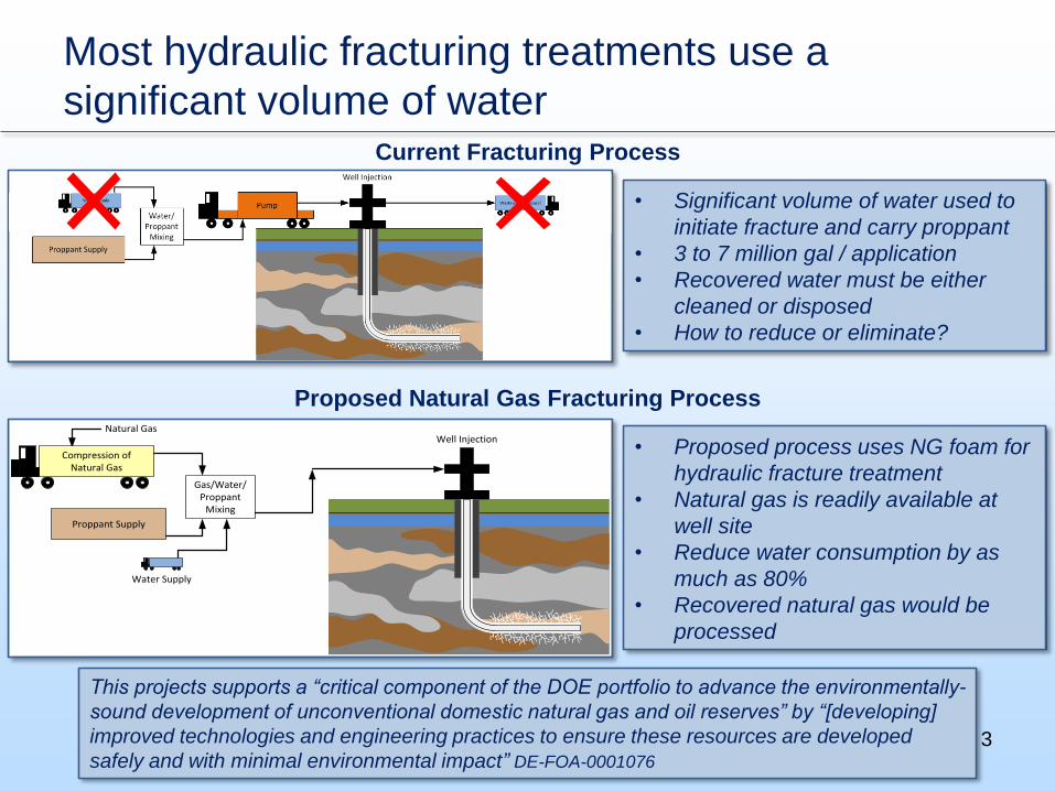
Most hydraulic fracturing treatments use a
significant volume of waterCurrent Fracturing Process
• Significant volume of water used to
initiate fracture and carry proppant
• 3 to 7 million gal / application
• Recovered water must be either
cleaned or disposed
• How to reduce or eliminate?
Gas/Water/Proppant
Mixing
Proppant Supply
Well InjectionNatural Gas
Compression of Natural Gas
Water Supply
• Proposed process uses NG foam for
hydraulic fracture treatment
• Natural gas is readily available at
well site
• Reduce water consumption by as
much as 80%
• Recovered natural gas would be
processed
Proposed Natural Gas Fracturing Process
This projects supports a “critical component of the DOE portfolio to advance the environmentally-
sound development of unconventional domestic natural gas and oil reserves” by “[developing]
improved technologies and engineering practices to ensure these resources are developed
safely and with minimal environmental impact” DE-FOA-0001076
3

4
Work to develop the NG fracturing process is
scheduled to occur over a three-year period
Project Objective
Develop a rugged, mobile, and economic system that can take natural
gas and prepare it for use in fracturing of gas shale to significantly
reduce water usage from traditional fracturing methods
Identify optimal process
for bringing the
wellhead gas to
injection pressure
(10,000 psia) and
temperature (ambient
±20 °F)
Year 1 (2015)
Complete a laboratory
scale test to validate
fracturing concept
Year 2 (2016)
Complete a field test to
validate the ability of the
system to operate at
field conditions
Year 3 (2017)

Initial work in 2015 focused on brainstorming
processes to generate high pressure NG
5
NG Process
On-site NG
500 psia
80°F 35 bbl/min
Water
Pumping
Water
14.7 psia
80°F 15 bbl/min
NG Foam
10,000 psia90°F
50 bbl/min
focus of initial work

Six processes, including direct compression and
multiple refrigeration cycles, were considered
6
Direct Compression N2 Refrigeration
Pre-Cooled Pre-Compressed
• Two additional liquefaction cycles developed (Cycles 5 & 6)
• Patent applications being explored

The cycles were modeled and specific energy was
estimated
7
• HYSYS® models used to
estimate specific energy (energy
required to produce unit mass of
compressed NG)
*all values normalized to direct compression specific energy
• Equipment footprint for
liquefaction cycles (e.g., coolers
to reject heat) found to be very
large
• Specific energy is a function of
gas composition and pressure /
temperature

In general, the amount of energy required for
liquefaction cycles is very high
8

With the top three cycles selected, additional work
focused on preliminary design and optimization
9
• Quotations & specs were
obtained for commercially
available equipment
• Equipment included:
centrifugal and
reciprocating compressors,
cryogenic liquid pumps,
PCHE, companders, air
coolers
• HYSYS models were
updated with specific
equipment performance
values: η, ΔP, ΔT• Cycles were optimized to
achieve lowest cycle
specific energy
• Process footprint estimates
were generated
• System costs were
estimated using vendor
quotations
Ariel JGC Compressor [1]
Cryostar HPP Quintuplex Pump [2]

Models were updated with quoted performance
specifications and optimized
10
*all values normalized to direct compression specific energy
from conceptual analysis
• Direct compression cycle:‒ Included the fewest number of
components
‒ Had the lowest equipment cost
• The cycle was selected for
continued development into project
years 2 & 3

A literature survey was conducted to identify
rheological properties of NG foam
11
• No published rheology data on fluids
foamed with methane/NG
• Foam is a non-Newtonian fluid
• CO2 and N2 foam trends:‒ Fluid viscosity changes with foam quality
‒ Temperature impacts viscosity (increasing T
decreases µ)
‒ Bubble size has minimal impact on foam µ
‒ Foam viscosity is dominated by foam quality
and base fluid viscosity
‒ Pressure has a small effect on viscosity
LNG StorageLNG Pump
LNG Heater/Heat Exchanger
Mixing ValveWater Pump
To Gas Flare
To Dirty Water Storage
Water/Surfactant Storage
Fracture Dynamics
Vaporizer
Separator
Water Flow Control/Recirculation
Vapor Return
Delta- P Test Section
Sight Glass
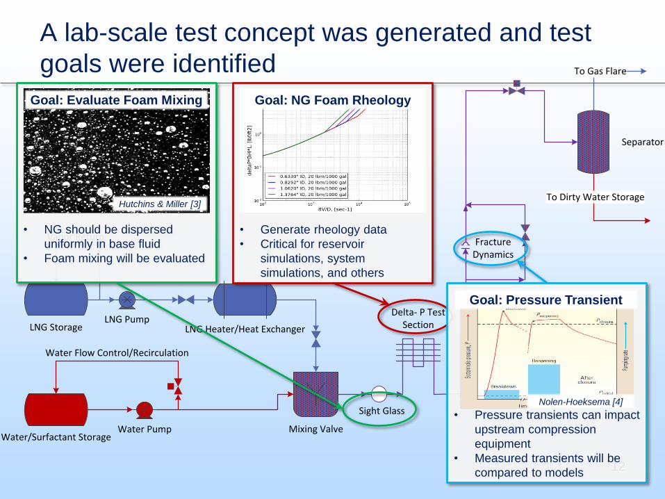
A lab-scale test concept was generated and test
goals were identified
12
• Generate rheology data
• Critical for reservoir
simulations, system
simulations, and others
Goal: NG Foam Rheology
• NG should be dispersed
uniformly in base fluid
• Foam mixing will be evaluated
Goal: Evaluate Foam Mixing
Hutchins & Miller [3]
• Pressure transients can impact
upstream compression
equipment
• Measured transients will be
compared to models
Goal: Pressure Transient
Nolen-Hoeksema [4]

Year 2 project work has focused on the detailed
design and construction of the lab-scale test stand
13
Parameter Parameter Range
Pressure (psia) 2500, 5000, and 7500
Flow Rate (gpm) 0.3 to 7
Shear Rate (s-1) 660 to 140,570
Natural Gas Fraction
(Quality, %)60, 70, and 80
Guar and Surfactant
Concentration
Guar: 30 lbm/1,000 gal
Surfactant: 5 gal/1000 gal
Delta-P Test Section
Diameter (in)0.125 to 0.270
Temperature (°F) 90, 125, and 160
Fracture Pressure
(psi)300 or 500
• Test matrix and test parameter
ranges are defined‒ Limits account for equipment operating
limits
‒ Test conducted at conditions that match
field conditions
• 17 test points
Year 2 Lab-Scale Test Parameters
• Significant effort to identify equipment
suitable for the rigorous test
conditions
CS&P Pump and J.M. Canty Sight-Glass [5-6]

Several accomplishments have been made and
additional tasks are planned for the future
14
Year 1 – System Design and Optimization
Brainstorm different paths for processing natural gas Complete
Identify top process (based on thermodynamics and cost/availability) Complete
Design lab scale test set-up Complete
Investigate the rheological properties of natural gas foams Complete
Year 2 – Lab Scale Testing
Procure equipment for test system In progress
Construct test system Aug./Sept. 2016
Commission test system October 2016
Complete Testing and analysis of data November 2016
Evaluate lab scale testing and identify successes and areas for improvement December 2016
Year 3 – Field Testing
Evaluate available test sites In progress
Set-up equipment at field location 2017
Run system in field and analyze data 2017
Estimate cost of industrial size system In progress
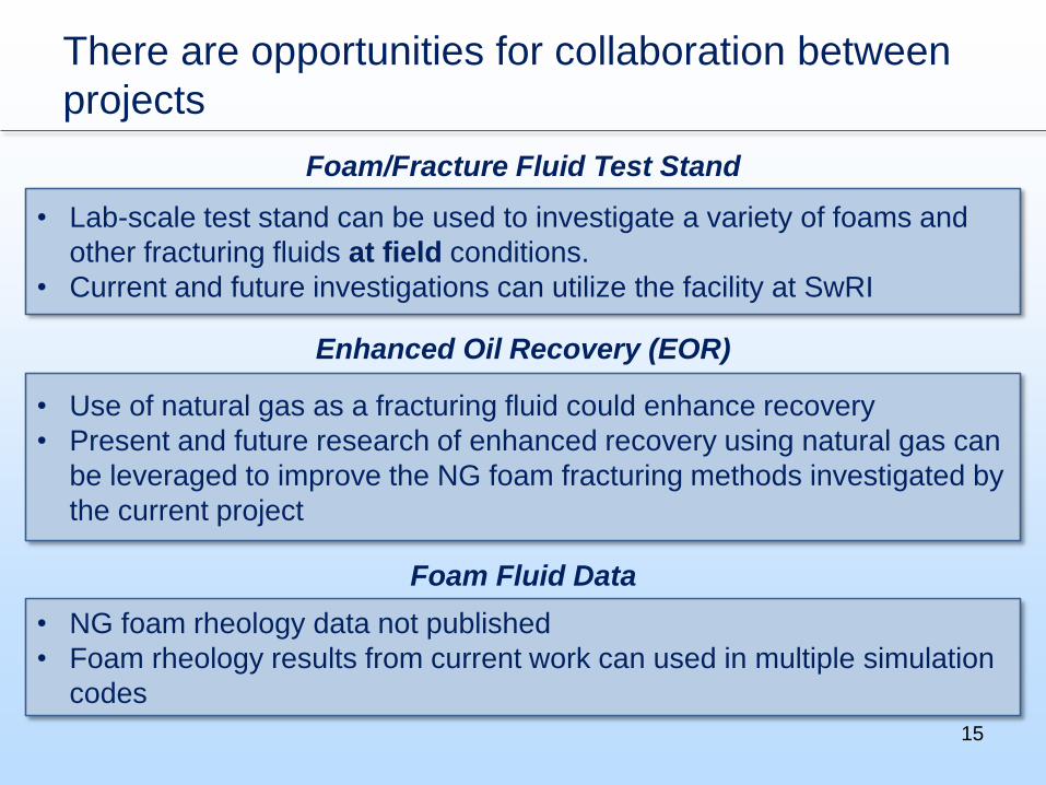
There are opportunities for collaboration between
projects
15
• Lab-scale test stand can be used to investigate a variety of foams and
other fracturing fluids at field conditions.
• Current and future investigations can utilize the facility at SwRI
Foam/Fracture Fluid Test Stand
• Use of natural gas as a fracturing fluid could enhance recovery
• Present and future research of enhanced recovery using natural gas can
be leveraged to improve the NG foam fracturing methods investigated by
the current project
Enhanced Oil Recovery (EOR)
• NG foam rheology data not published
• Foam rheology results from current work can used in multiple simulation
codes
Foam Fluid Data
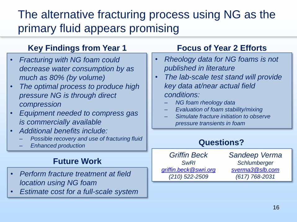
The alternative fracturing process using NG as the
primary fluid appears promising
16
• Fracturing with NG foam could
decrease water consumption by as
much as 80% (by volume)
• The optimal process to produce high
pressure NG is through direct
compression
• Equipment needed to compress gas
is commercially available
• Additional benefits include:‒ Possible recovery and use of fracturing fluid
‒ Enhanced production
Key Findings from Year 1
• Rheology data for NG foams is not
published in literature
• The lab-scale test stand will provide
key data at/near actual field
conditions:‒ NG foam rheology data
‒ Evaluation of foam stability/mixing
‒ Simulate fracture initiation to observe
pressure transients in foam
Focus of Year 2 Efforts
• Perform fracture treatment at field
location using NG foam
• Estimate cost for a full-scale system
Future WorkGriffin Beck
SwRI
(210) 522-2509
Sandeep VermaSchlumberger
(617) 768-2031
Questions?

17
Appendix

Project Organization
18
PI
Melissa Poerner, P.E. &
Griffin Beck (interim PI)
Co-PI
Dr. Klaus Brun & Kevin Hoopes
Engineering Support
Craig Nolen & Charles Krouse
Contracts
Mary Lepel
PI
Dr. Sandeep Verma (SDR)
PM
Garud Sridhar
Engineering Support
Alhad Phatak, Terrence
Goettsch, & Carina Pechiney
Engineering Consultation
Dr. John Brisson (MIT)

Project Schedule
19

20
Bibliography
• At the time of presentation, no publications have resulted
from this project work

21
References
1. Ariel Corporation, 2016, retrieved from https://www.arielcorp.com/JGC-JGD-JGF/
2. Cyrostar, 2016, retrieved from www.cryostar.com/pdf/data-sheet/en/hpp.pdf
3. Hutchins, R. D., and Miller, M. J., 2003, “A Circulating Foam Loop for Evaluating Foam at
Conditions of Use,” Society of Petroleum Engineers, Houston, TX, p. 10. SPE-80242.
4. Nolen-Hoeksema, R., 2013, “Elements of Hydraulic Fracturing,” Oilfield Rev., 25(2), pp. 51–52.
5. CS&P, 2016, retrieved from www.csphouston.com/industrial_cryogenic/ICP45-01202010.pdf
6. J.M. Canty, 2016, “TA7461-1 F700 Series Flanged Sight Flows”, retrieved from
http://www.jmcanty.com/product/f700-series-flanged-sight-flows/