Development and Experimental Investigation of … · Experimental Investigation of Thermopile...
3
Research Article Open Access Waqas et al., J Appl Mech Eng 2016, 5:5 DOI: 10.4172/2168-9873.1000223 Research Article Open Access Journal of Applied Mechanical Engineering J o u r n a l o f A p p l i e d M e c h a n i c a l E n g i n e e r i n g ISSN: 2168-9873 Volume 5 • Issue 5 • 1000223 J Appl Mech Eng ISSN:2168-9873 JAME, an open access journal *Corresponding author: Waqas MS, Department of Mechanical and Aeronautical Engineering, University of Engineering and Technology Taxila P.O Box 46000 Taxila, Pakistan, Tel: +92 312 5093954; E-mail: [email protected] Received June 04, 2016; Accepted June 30, 2016; Published July 03, 2016 Citation: Waqas MS, Muhammad Ali H, Malik AH (2016) Development and Experimental Investigation of Thermopile Sensor with Dynamic Effects. J Appl Mech Eng 5: 223. doi:10.4172/2168-873.1000223 Copyright: © 2016 Waqas MS, et al. This is an open-access article distributed under the terms of the Creative Commons Attribution License, which permits unrestricted use, distribution, and reproduction in any medium, provided the original author and source are credited. Development and Experimental Investigation of Thermopile Sensor with Dynamic Effects Waqas MS*, Muhammad Ali H and Malik AH Department of Mechanical and Aeronautical Engineering, University of Engineering and Technology Taxila P.O Box 46000 Taxila, Pakistan Abstract A highly sensitive ten junction thermopile sensor comprising of twenty K type thermocouples (Alumel/Chromel) with the thermo power of 0.040002 mv/°C fabricated on a barrier terminal with terminal lugs of speciic material having thickness of 25.4 mm. The developed sensor can measure the temperature difference ∆T (°C) up to 0.01°C. An error of 15.73% recorded when the thermopile sensor junction is placed under high humidity and the relative humidity (RH value) goes to 100%. The generation of humidity is through the Marcet boiler steam process and control with gate valve. High temperatures have no significant effect on the junction of thermopile sensor. Keywords: 10 junction; ermopile; Humidity; Temperature; Sensitivity Introduction In thermodynamics there are a lot of means of investigating the observed thermal and electric properties. But they do not have the ability to provide model to explain their behavior. A thermopile sensor is the combination of series of interconnected thermocouples array working on the principle of Seebeck effect [1]. e Seebeck effect is the conversion of thermoelectrically differentials into electrical voltage. Generally K type thermocouple measures the temperature differences ∆T (°C) up to 0.1°C which is insufficient for highly sensitive system for example in heat exchanger where the temperature drops in a micro level so a simple thermocouple fails to measure that drop and the effect of high temperature and humidity may alter the results. ermopile structure is made of material containing Al and silicon which have the ability to measure improper liquid flow across it. e structure is equally heated on the top of membrane SU8. is membrane can compensate a large number of thermocouples according to the requirement forming thermocouple junctions. Forming this combination it has the sensitivity up to 40 µv/C at 2 mw heating power [2]. e heating capacity is controlled by the flowing current and measure generated voltage over heater. When there is lot of change in thermal gradient so for the reduction of these changes a small microchip channel made on the membrane over very small distances [3]. A thermopile structure consist of 196 serially interconnected thermocouples of titanium/nitride with a membrane called SU-8 consist of bulk silicon on the structure have the sensitivity of 5.6 µv/C. the membrane material have itself lower thermal conductivity so lower sensitivity. Flexible mounted sensor having the ability to measure up to 46.54 µv/C with the free silicon nitride membrane thickness of 75.56 µm [4]. e membrane is installed using micro machined techniques called photolithographic. e distance between junctions is quite large which lower the sensitivity [5]. e development of ten junction comprising twenty number of K type thermocouples structure, which have the output efficiency of measuring temperature difference up to 0.01°C and its response under dynamic conditions i.e., high temperature and humidity Figure 1. Sensor Concept e key element of thermopile structure comprising of terminal barriers, terminal lugs with polarity, K type thermocouples. e whole structure is placed in a steel box with varying conditions of temperature and humidity. e outputs of thermopile were placed in a glass tube which further placed in hot and cold water bath for maintaining 0°C reference temperature and zero relative humidity. e thermocouple is composed of 95% of nickel 10% of chromium 2% of manganese and little composition of aluminum and silicon. e Seebeck coefficient of whole thermopile sensor is 0.040002 mv/°C containing twenty number of K type thermocouple making ten junctions [6]. e insulation covered the each thermocouple is made of glass fiber which can bear temperature as low as -30°C to as high as 540°C. Figure 1: Showing the experimental setup with thermopile structure and steam generation and heating process including the hygrometer and multimeter for detection of output voltages.
Transcript of Development and Experimental Investigation of … · Experimental Investigation of Thermopile...
Research Article Open Access
Waqas et al., J Appl Mech Eng 2016, 5:5 DOI: 10.4172/2168-9873.1000223
Research Article Open Access
Journal of Applied Mechanical EngineeringJo
urna
l of A
pplied Mechanical Engineering
ISSN: 2168-9873
Volume 5 • Issue 5 • 1000223J Appl Mech EngISSN:2168-9873 JAME, an open access journal
*Corresponding author: Waqas MS, Department of Mechanical and Aeronautical Engineering, University of Engineering and Technology Taxila P.O Box 46000Taxila, Pakistan, Tel: +92 312 5093954; E-mail: [email protected]
Received June 04, 2016; Accepted June 30, 2016; Published July 03, 2016
Citation: Waqas MS, Muhammad Ali H, Malik AH (2016) Development and Experimental Investigation of Thermopile Sensor with Dynamic Effects. J Appl Mech Eng 5: 223. doi:10.4172/2168-873.1000223
Copyright: © 2016 Waqas MS, et al. This is an open-access article distributed under the terms of the Creative Commons Attribution License, which permits unrestricted use, distribution, and reproduction in any medium, provided the original author and source are credited.
Development and Experimental Investigation of Thermopile Sensor with Dynamic EffectsWaqas MS*, Muhammad Ali H and Malik AHDepartment of Mechanical and Aeronautical Engineering, University of Engineering and Technology Taxila P.O Box 46000 Taxila, Pakistan
Abstract
A highly sensitive ten junction thermopile sensor comprising of twenty K type thermocouples (Alumel/Chromel) with the thermo power of 0.040002 mv/°C fabricated on a barrier terminal with terminal lugs of speciic material having thickness of 25.4 mm. The developed sensor can measure the temperature difference ∆T (°C) up to 0.01°C. An error of 15.73% recorded when the thermopile sensor junction is placed under high humidity and the relative humidity (RH value) goes to 100%. The generation of humidity is through the Marcet boiler steam process and control with gate valve. High temperatures have no significant effect on the junction of thermopile sensor.
Keywords: 10 junction; Thermopile; Humidity; Temperature;Sensitivity
IntroductionIn thermodynamics there are a lot of means of investigating the
observed thermal and electric properties. But they do not have the ability to provide model to explain their behavior. A thermopile sensor is the combination of series of interconnected thermocouples array working on the principle of Seebeck effect [1]. The Seebeck effect is the conversion of thermoelectrically differentials into electrical voltage.
Generally K type thermocouple measures the temperature differences ∆T (°C) up to 0.1°C which is insufficient for highly sensitive system for example in heat exchanger where the temperature drops in a micro level so a simple thermocouple fails to measure that drop and the effect of high temperature and humidity may alter the results.
Thermopile structure is made of material containing Al and silicon which have the ability to measure improper liquid flow across it. The structure is equally heated on the top of membrane SU8. This membrane can compensate a large number of thermocouples according to the requirement forming thermocouple junctions. Forming this combination it has the sensitivity up to 40 µv/C at 2 mw heating power [2]. The heating capacity is controlled by the flowing current and measure generated voltage over heater. When there is lot of change in thermal gradient so for the reduction of these changes a small microchip channel made on the membrane over very small distances [3].
A thermopile structure consist of 196 serially interconnected thermocouples of titanium/nitride with a membrane called SU-8 consist of bulk silicon on the structure have the sensitivity of 5.6 µv/C. the membrane material have itself lower thermal conductivity so lower sensitivity.
Flexible mounted sensor having the ability to measure up to 46.54 µv/C with the free silicon nitride membrane thickness of 75.56 µm [4].
The membrane is installed using micro machined techniques called photolithographic. The distance between junctions is quite large which lower the sensitivity [5].
The development of ten junction comprising twenty number of K type thermocouples structure, which have the output efficiency of measuring temperature difference up to 0.01°C and its response under dynamic conditions i.e., high temperature and humidity Figure 1.
Sensor Concept The key element of thermopile structure comprising of terminal
barriers, terminal lugs with polarity, K type thermocouples.
The whole structure is placed in a steel box with varying conditions of temperature and humidity. The outputs of thermopile were placed in a glass tube which further placed in hot and cold water bath for maintaining 0°C reference temperature and zero relative humidity.
The thermocouple is composed of 95% of nickel 10% of chromium 2% of manganese and little composition of aluminum and silicon. The Seebeck coefficient of whole thermopile sensor is 0.040002 mv/°C containing twenty number of K type thermocouple making ten junctions [6]. The insulation covered the each thermocouple is made of glass fiber which can bear temperature as low as -30°C to as high as 540°C.
Figure 1: Showing the experimental setup with thermopile structure and steam generation and heating process including the hygrometer and multimeter for detection of output voltages.
Page 2 of 3
Citation: Waqas MS, Muhammad Ali H, Malik AH (2016) Development and Experimental Investigation of Thermopile Sensor with Dynamic Effects. J Appl Mech Eng 5: 223. doi:10.4172/2168-873.1000223
Volume 5 • Issue 5 • 1000223J Appl Mech EngISSN:2168-9873 JAME, an open access journal
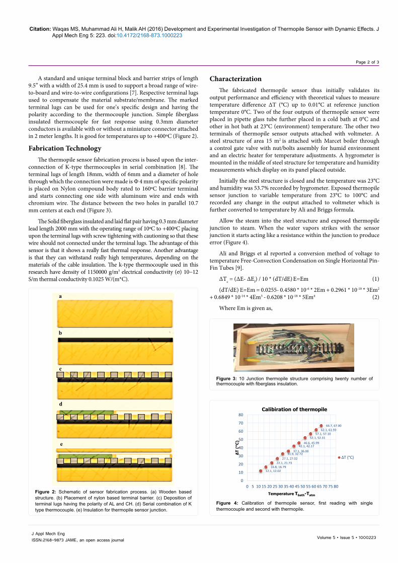
A standard and unique terminal block and barrier strips of length 9.5” with a width of 25.4 mm is used to support a broad range of wire-to-board and wire-to-wire configurations [7]. Respective terminal lugs used to compensate the material substrate/membrane. The marked terminal lugs can be used for one’s specific design and having the polarity according to the thermocouple junction. Simple fiberglass insulated thermocouple for fast response using 0.3mm diameter conductors is available with or without a miniature connector attached in 2 meter lengths. It is good for temperatures up to +400ºC (Figure 2).
Fabrication TechnologyThe thermopile sensor fabrication process is based upon the inter-
connection of K-type thermocouples in serial combination [8]. The terminal lugs of length 18mm, width of 6mm and a diameter of hole through which the connection were made is Φ 4 mm of specific polarity is placed on Nylon compound body rated to 160ºC barrier terminal and starts connecting one side with aluminum wire and ends with chromium wire. The distance between the two holes in parallel 10.7 mm centers at each end (Figure 3).
The Solid fiberglass insulated and laid flat pair having 0.3 mm diameter lead length 2000 mm with the operating range of 10ºC to +400ºC placing upon the terminal lugs with screw tightening with cautioning so that these wire should not connected under the terminal lugs. The advantage of this sensor is that it shows a really fast thermal response. Another advantage is that they can withstand really high temperatures, depending on the materials of the cable insulation. The k-type thermocouple used in this research have density of 1150000 g/m3 electrical conductivity (σ) 10−12 S/m thermal conductivity 0.1025 W/(m*C).
Characterization The fabricated thermopile sensor thus initially validates its
output performance and efficiency with theoretical values to measure temperature difference ∆T (°C) up to 0.01°C at reference junction temperature 0°C. Two of the four outputs of thermopile sensor were placed in pipette glass tube further placed in a cold bath at 0°C and other in hot bath at 23°C (environment) temperature. The other two terminals of thermopile sensor outputs attached with voltmeter. A steel structure of area 15 m2 is attached with Marcet boiler through a control gate valve with nut/bolts assembly for humid environment and an electric heater for temperature adjustments. A hygrometer is mounted in the middle of steel structure for temperature and humidity measurements which display on its panel placed outside.
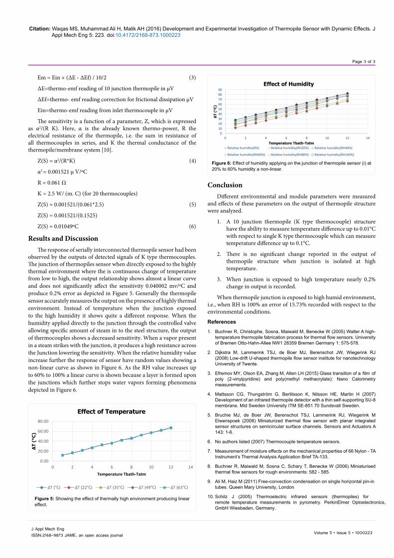
Initially the steel structure is closed and the temperature was 23°C and humidity was 53.7% recorded by hygrometer. Exposed thermopile sensor junction to variable temperature from 23°C to 100°C and recorded any change in the output attached to voltmeter which is further converted to temperature by Ali and Briggs formula.
Allow the steam into the steel structure and exposed thermopile junction to steam. When the water vapors strikes with the sensor junction it starts acting like a resistance within the junction to produce error (Figure 4).
Ali and Briggs et al reported a conversion method of voltage to temperature Free-Convection Condensation on Single Horizontal Pin-Fin Tubes [9].
ΔTc = (ΔE- ΔEf) / 10 * (dT/dE) E=Em (1)
(dT/dE) E=Em = 0.0255- 0.4580 * 10-6 * 2Em + 0.2961 * 10-10 * 3Em2 + 0.6849 * 10-14 * 4Em3 - 0.6208 * 10-18 * 5Em4 (2)
Where Em is given as,
a
b
c
d
e
Figure 2: Schematic of sensor fabrication process. (a) Wooden based structure. (b) Placement of nylon based terminal barrier. (c) Deposition of terminal lugs having the polarity of AL and CH. (d) Serial combination of K type thermocouple. (e) Insulation for thermopile sensor junction.
Figure 3: 10 Junction thermopile structure comprising twenty number of thermocouple with fiberglass insulation.
12.1, 12.0216.8, 16.79
22.1, 21.7327.1, 27.02
31.9, 32.7237.1, 36.00
42.1, 42.1746.6, 45.99
52.1, 52.3157.1, 57.10
62.1, 61.9366.7, 67.00
0
10
20
30
40
50
60
70
80
0 5 10 15 20 25 30 35 40 45 50 55 60 65 70 75 80
∆T
(°C
)
Temperature Tbath-Tatm
Calibiration of thermopile
∆T (°C)
Figure 4: Calibration of thermopile sensor, first reading with single thermocouple and second with thermopile.
Page 3 of 3
Citation: Waqas MS, Muhammad Ali H, Malik AH (2016) Development and Experimental Investigation of Thermopile Sensor with Dynamic Effects. J Appl Mech Eng 5: 223. doi:10.4172/2168-873.1000223
Volume 5 • Issue 5 • 1000223J Appl Mech EngISSN:2168-9873 JAME, an open access journal
Em = Ein + (ΔE - ΔEf) / 10/2 (3)
ΔE=thermo-emf reading of 10 junction thermopile in µV
ΔEf=thermo- emf reading correction for frictional dissipation µV
Ein=thermo-emf reading from inlet thermocouple in µV
The sensitivity is a function of a parameter, Z, which is expressed as α2/(R K). Here, α is the already known thermo-power, R the electrical resistance of the thermopile, i.e. the sum in resistance of all thermocouples in series, and K the thermal conductance of the thermopile/membrane system [10].
Z(S) = α2/(R*K) (4)
α2 = 0.001521 μ V/ºC
R = 0.061 Ω
K = 2.5 W/ (m. C) (for 20 thermocouples)
Z(S) = 0.001521/(0.061*2.5) (5)
Z(S) = 0.001521/(0.1525)
Z(S) = 0.01049ºC (6)
Results and DiscussionThe response of serially interconnected thermopile sensor had been
observed by the outputs of detected signals of K type thermocouples. The junction of thermopiles sensor when directly exposed to the highly thermal environment where the is continuous change of temperature from low to high, the output relationship shows almost a linear curve and does not significantly affect the sensitivity 0.040002 mv/ºC and produce 0.2% error as depicted in Figure 5. Generally the thermopile sensor accurately measures the output on the presence of highly thermal environment. Instead of temperature when the junction exposed to the high humidity it shows quite a different response. When the humidity applied directly to the junction through the controlled valve allowing specific amount of steam in to the steel structure, the output of thermocouples shows a decreased sensitivity. When a vapor present in a steam strikes with the junction, it produces a high resistance across the Junction lowering the sensitivity. When the relative humidity value increase further the response of sensor have random values showing a non-linear curve as shown in Figure 6. As the RH value increases up to 60% to 100% a linear curve is shown because a layer is formed upon the junctions which further stops water vapors forming phenomena depicted in Figure 6.
Conclusion Different environmental and module parameters were measured
and effects of these parameters on the output of thermopile structure were analyzed.
1. A 10 junction thermopile (K type thermocouple) structure have the ability to measure temperature difference up to 0.01°C with respect to single K type thermocouple which can measure temperature difference up to 0.1°C.
2. There is no significant change reported in the output of thermopile structure when junction is isolated at high temperature.
3. When junction is exposed to high temperature nearly 0.2% change in output is recorded.
When thermopile junction is exposed to high humid environment, i.e., when RH is 100% an error of 15.73% recorded with respect to the environmental conditions.
References
1. Buchner R, Christophe, Sosna, Maiwald M, Benecke W (2005) Walter A high-temperature thermopile fabrication process for thermal flow sensors. University of Bremen Otto-Hahn-Allee NW1 28359 Bremen Germany 1: 575-578.
2. Dijkstra M, Lammerink TSJ, de Boer MJ, Berenschot JW, Wiegerink RJ (2008) Low-drift U-shaped thermopile flow sensor institute for nanotechnology University of Twente.
3. Efremov MY, Olson EA, Zhang M, Allen LH (2015) Glass transition of a film of poly (2-vinylpyridine) and poly(methyl methacrylate): Nano Calorimetry measurements.
4. Mattsson CG, Thungström G, Bertilsson K, Nilsson HE, Martin H (2007) Development of an infrared thermopile detector with a thin self-supporting SU-8 membrane. Mid Sweden University ITM SE-851 70 Sundsvall Sweden.
5. Bruchie MJ, de Boer JW, Berenschot TSJ, Lammerink RJ, Wiegerink M Elwenspoek (2008) Miniaturized thermal flow sensor with planar integrated sensor structures on semicircular surface channels. Sensors and Actuators A 143: 1-6.
6. No authors listed (2007) Thermocouple temperature sensors..
7. Measurement of moisture effects on the mechanical properties of 66 Nylon - TA Instrument’s Thermal Analysis Application Brief TA-133.
8. Buchner R, Maiwald M, Sosna C, Schary T, Benecke W (2006) Miniaturised thermal flow sensors for rough environments: 582 - 585.
9. Ali M, Haiz M (2011) Free-convection condensation on single horizontal pin-in tubes. Queen Mary University, London.
10. Schilz J (2005) Thermoelectric infrared sensors (thermopiles) for remote temperature measurements in pyrometry. PerkinElmer Optoelectronics, GmbH Wiesbaden, Germany.
0.00
20.00
40.00
60.00
80.00
0 2 4 6 8 10 12 14
∆T
(°C
)
Temperature Tbath-Tatm
Effect of Temperature
∆T (°C) ∆T (22°C) ∆T (35°C) ∆T (49°C) ∆T (63°C)
Figure 5: Showing the effect of thermally high environment producing linear effect.
0102030405060708090
0 2 4 6 8 10 12 14
∆T
(°C
)
Temperature Tbath-Tatm
Effect of Humidity
Relative humidity(0%) Relative humidity(RH20%) Relative humidity(RH40%)
Relative humidity(RH60%) Relative humidity(RH80%) Relative humidity(RH100%)
Figure 6: Effect of humidity applying on the junction of thermopile sensor (i) at 20% to 60% humidity a non-linear.