Transfer Student Success: Building Partnerships Across Departments and Institutions

Developing high value partnershipsGrowing together across the power products value chain
Rev.1 Dec.12
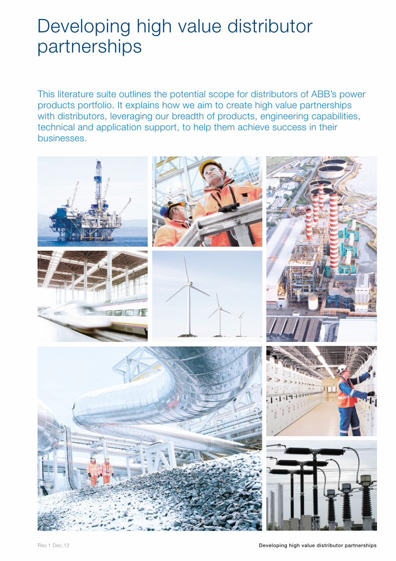
This literature suite outlines the potential scope for distributors of ABB’s power products portfolio. It explains how we aim to create high value partnerships with distributors, leveraging our breadth of products, engineering capabilities, technical and application support, to help them achieve success in their businesses.
Developing high value distributor partnerships
Developing high value distributor partnerships
Rev.1 Dec.12
We believe that distributors are a vital element in building and developing ABB’s customer value chain. Our engineering, manufacturing and logistics capabilities combine with the detailed local market knowledge and expertise provided by our distributors to help drive sales both broader and deeper across the world.
We recognize that distributors are highly valued partners of utilities, OEMs, system integrators and industrial and commercial customers.
We are committed to supporting distributors in creating these high value customer partnerships by providing a comprehensive distributor program and product portfolio that embraces low, medium and high voltage products and systems.
We understand that distributors provide the best possible long term value for their customers by making their products and services supply chain more efficient and reliable.
Our sustainable focus on distributors is a key priority for ABB. We have built on this to create the ABB distributor partnership promise based on: – the strength of the global ABB brand – our ability to create market pull – a vast and continually developing product range – outstanding product quality – first class engineering and technical support – flexibility to adapt products to specific market or customer needs – extensive training as required (on-site, on-line or factory-based) – our desire to be easy to do business with
In essence, ABB’s commitment to distributors is to develop together a long-term partnership that delivers true mutual benefits and the best possible customer service.
Our partnership promise for distributors
Our partnership promise for distributors
Rev.1 Dec.12
About ABB
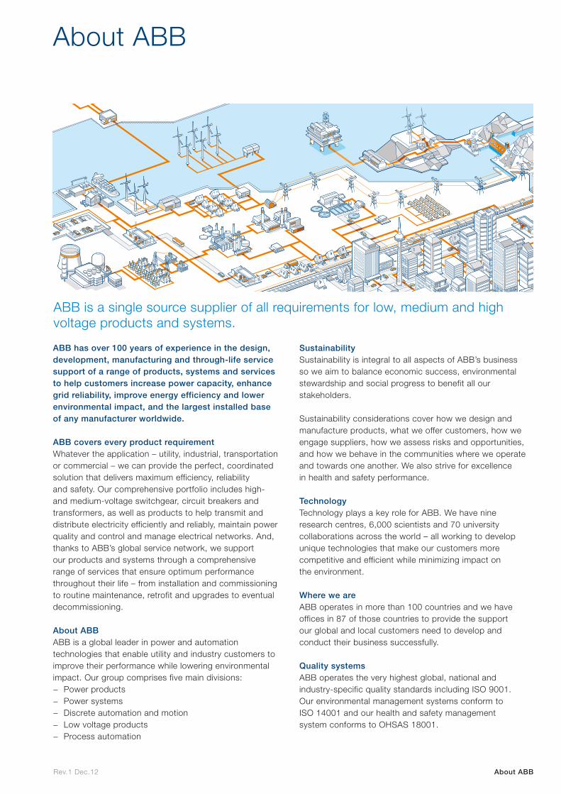
ABB has over 100 years of experience in the design, development, manufacturing and through-life service support of a range of products, systems and services to help customers increase power capacity, enhance grid reliability, improve energy efficiency and lower environmental impact, and the largest installed base of any manufacturer worldwide.
ABB covers every product requirementWhatever the application – utility, industrial, transportation or commercial – we can provide the perfect, coordinated solution that delivers maximum efficiency, reliability and safety. Our comprehensive portfolio includes high- and medium-voltage switchgear, circuit breakers and transformers, as well as products to help transmit and distribute electricity efficiently and reliably, maintain power quality and control and manage electrical networks. And, thanks to ABB’s global service network, we support our products and systems through a comprehensive range of services that ensure optimum performance throughout their life – from installation and commissioning to routine maintenance, retrofit and upgrades to eventual decommissioning.
About ABBABB is a global leader in power and automation technologies that enable utility and industry customers to improve their performance while lowering environmental impact. Our group comprises five main divisions:
− Power products − Power systems − Discrete automation and motion − Low voltage products − Process automation
Sustainability Sustainability is integral to all aspects of ABB’s business so we aim to balance economic success, environmental stewardship and social progress to benefit all our stakeholders.
Sustainability considerations cover how we design and manufacture products, what we offer customers, how we engage suppliers, how we assess risks and opportunities, and how we behave in the communities where we operate and towards one another. We also strive for excellence in health and safety performance.
Technology Technology plays a key role for ABB. We have nine research centres, 6,000 scientists and 70 university collaborations across the world – all working to develop unique technologies that make our customers more competitive and efficient while minimizing impact on the environment.
Where we are ABB operates in more than 100 countries and we have offices in 87 of those countries to provide the support our global and local customers need to develop and conduct their business successfully.
Quality systemsABB operates the very highest global, national and industry-specific quality standards including ISO 9001. Our environmental management systems conform to ISO 14001 and our health and safety management system conforms to OHSAS 18001.
ABB is a single source supplier of all requirements for low, medium and high voltage products and systems.
About ABB
Rev.1 Dec.12
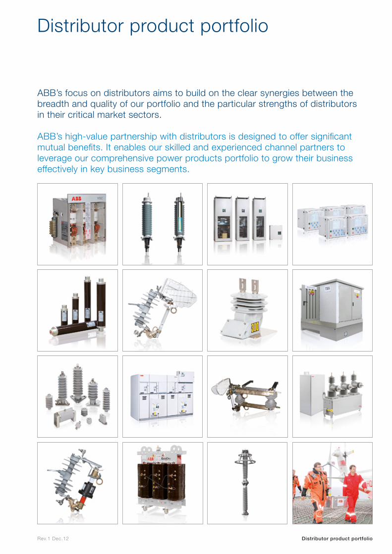
ABB’s focus on distributors aims to build on the clear synergies between the breadth and quality of our portfolio and the particular strengths of distributors in their critical market sectors.
ABB’s high-value partnership with distributors is designed to offer significant mutual benefits. It enables our skilled and experienced channel partners to leverage our comprehensive power products portfolio to grow their business effectively in key business segments.
Distributor product portfolio
Distributor product portfolio
Rev.1 Dec.12
Industry sectors
Industry sectors
Power transmission and distributionABB provides the world’s most comprehensive range of power generation, transmission and distribution solutions to help address the challenges of balancing rising demand for power with increasing concern for the environment.
Airports and port facilitiesABB has developed a set of innovative power product solutions for passenger and cargo handling applications that reduce emissions, save energy and keep noise and vibration to a minimum.
Oil and gasABB is a proven performer in the oil and gas industry, with an expanding range of power product solutions for the hydrocarbon supply chain, encompassing production, processing, transportation, storage and distribution.
Automotive industryABB power products are used by automotive manufacturers and components makers around the world to improve productivity, product quality and employee safety, processing, transportation, storage and distribution.
Railways and traction power supply systemsABB helps to keep the world moving with new sustainable approaches that enable customers to use energy effectively, creating a low carbon railway industry that operates with maximum efficiency and reliability.
Commercial infrastructures – shopping malls etcABB power products ensure the total reliability and continuity of supply essential for developers and operators of commercial buildings such as shopping malls and hotels while also helping to increase their energy efficiency.
Mining industryABB is a world leading supplier for the mining and mineral processing Industries, offering complete and innovative plant electrification solutions for the whole production chain.
WaterABB offers enhanced, efficient and reliable power products for applications throughout the complete water cycle from collection, purification and transportation to distribution and re-use.
Industrial and constructionABB offers a complete range of power products to deliver the ideal combination of reliability, safety and energy efficiency in any industrial project.
RenewablesABB offers a comprehensive range of power products developed to meet the specific needs of renewable energy customers throughout the generation train, from wind turbine or solar panel to grid connection.
Sewage/chemical/cement plantABB’s technical expertise and advanced power products help optimize plant performance while meeting critical safety standards to ensure maximum uptime and continuity of operation.
Data centersABB’s approach to data centers ranges from comprehensive power solutions to state-of-the-art monitoring and control systems that optimize server performance, energy use and cooling.
ABB enables distributors to deliver world-class products and services in these key industry sectors:
Rev.1 Dec.12
Product portfolio matrix
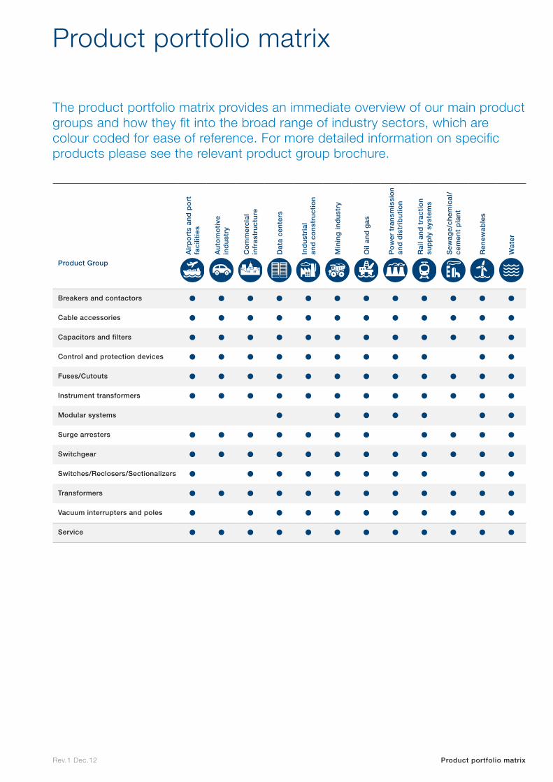
The product portfolio matrix provides an immediate overview of our main product groups and how they fit into the broad range of industry sectors, which are colour coded for ease of reference. For more detailed information on specific products please see the relevant product group brochure.
Product portfolio matrix
Air
po
rts
and
po
rt
faci
litie
s
Au
tom
oti
ve
ind
ust
ry
Co
mm
erci
al
infr
astr
uct
ure
Dat
a ce
nte
rs
Ind
ust
rial
an
d c
on
stru
ctio
n
Min
ing
ind
ust
ry
Oil
and
gas
Po
wer
tra
nsm
issi
on
and
dis
trib
uti
on
Rai
l an
d t
ract
ion
sup
ply
sys
tem
s
Sew
age/
chem
ical
/ce
men
t p
lan
t
Ren
ewab
les
Wat
er
Product Group
Breakers and contactors • • • • • • • • • • • •Cable accessories • • • • • • • • • • • •Capacitors and filters • • • • • • • • • • • •Control and protection devices • • • • • • • • • • •Fuses/Cutouts • • • • • • • • • • • •Instrument transformers • • • • • • • • • • • •Modular systems • • • • • • •Surge arresters • • • • • • • • • • •Switchgear • • • • • • • • • • • •Switches/Reclosers/Sectionalizers • • • • • • • • • •Transformers • • • • • • • • • • • •Vacuum interrupters and poles • • • • • • • • • • •Service • • • • • • • • • • • •

Breakers and contactors
Breakers and
co
ntactors
Rev.1 Dec.12 Breakers and contactors
Breakers and contactors
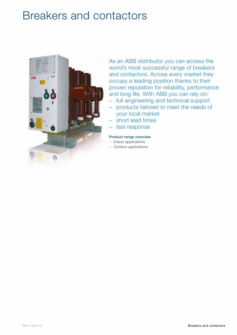
As an ABB distributor you can access the world’s most successful range of breakers and contactors. Across every market they occupy a leading position thanks to their proven reputation for reliability, performance and long life. With ABB you can rely on: – full engineering and technical support – products tailored to meet the needs of
your local market – short lead times – fast response
Product range overview − Indoor applications − Outdoor applications

Indoor applications
Indo
or
app
lications
Rev.1 Dec.12
VD4Vacuum circuit breaker
Breakers and contactors | Indoor applications| Indoor circuit breakers and contactors | VD4
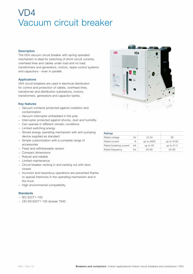
DescriptionThe VD4 vacuum circuit breaker with spring operated mechanism is ideal for switching of short-circuit currents, overhead lines and cables under load and no load, transformers and generators, motors, ripple control systems and capacitors – even in parallel.
ApplicationsVD4 circuit breakers are used in electrical distribution for control and protection of cables, overhead lines, transformer and distribution substations, motors, transformers, generators and capacitor banks.
Key features − Vacuum contacts protected against oxidation and
contamination − Vacuum interrupter embedded in the pole − Interrupter protected against shocks, dust and humidity − Can operate in different climatic conditions − Limited switching energy − Stored energy operating mechanism with anti-pumping
device supplied as standard − Simple customization with a complete range of
accessories − Fixed and withdrawable version − Compact dimensions − Robust and reliable − Limited maintenance − Circuit breaker racking in and racking out with door
closed − Incorrect and hazardous operations are prevented thanks
to special interlocks in the operating mechanism and in the truck
− High environmental compatibility
Standards − IEC 62271-100 − CEI EN 62271-100 dossier 7642
Ratings
Rated voltage kV 12-24 36
Rated current A up to 4000 up to 3150
Rated breaking current kA up to 50 up to 31.5
Rated frequency Hz 50-60 50-60
Rev.1 Dec.12 Breakers and contactors | Indoor applications | Indoor circuit breakers and contactors | eVD4
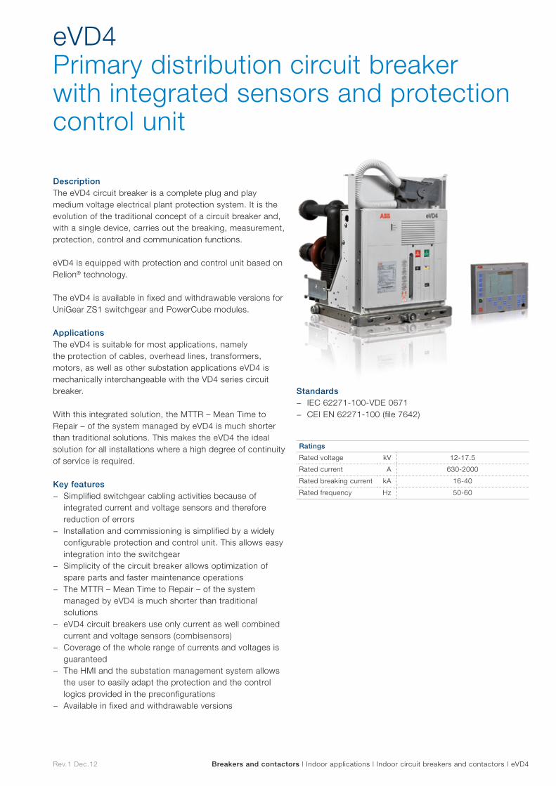
eVD4Primary distribution circuit breaker with integrated sensors and protection control unit
DescriptionThe eVD4 circuit breaker is a complete plug and play medium voltage electrical plant protection system. It is the evolution of the traditional concept of a circuit breaker and, with a single device, carries out the breaking, measurement, protection, control and communication functions.
eVD4 is equipped with protection and control unit based on Relion® technology.
The eVD4 is available in fixed and withdrawable versions for UniGear ZS1 switchgear and PowerCube modules.
ApplicationsThe eVD4 is suitable for most applications, namely the protection of cables, overhead lines, transformers, motors, as well as other substation applications eVD4 is mechanically interchangeable with the VD4 series circuit breaker.
With this integrated solution, the MTTR – Mean Time to Repair – of the system managed by eVD4 is much shorter than traditional solutions. This makes the eVD4 the ideal solution for all installations where a high degree of continuity of service is required.
Key features − Simplified switchgear cabling activities because of
integrated current and voltage sensors and therefore reduction of errors
− Installation and commissioning is simplified by a widely configurable protection and control unit. This allows easy integration into the switchgear
− Simplicity of the circuit breaker allows optimization of spare parts and faster maintenance operations
− The MTTR – Mean Time to Repair – of the system managed by eVD4 is much shorter than traditional solutions
− eVD4 circuit breakers use only current as well combined current and voltage sensors (combisensors)
− Coverage of the whole range of currents and voltages is guaranteed
− The HMI and the substation management system allows the user to easily adapt the protection and the control logics provided in the preconfigurations
− Available in fixed and withdrawable versions
Standards − IEC 62271-100-VDE 0671 − CEI EN 62271-100 (file 7642)
Ratings
Rated voltage kV 12-17.5
Rated current A 630-2000
Rated breaking current kA 16-40
Rated frequency Hz 50-60
Rev.1 Dec.12
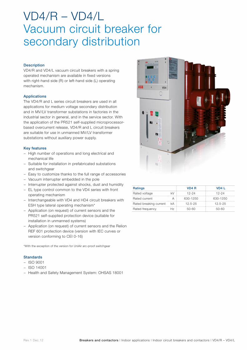
VD4/R – VD4/L Vacuum circuit breaker for secondary distribution
Breakers and contactors | Indoor applications | Indoor circuit breakers and contactors | VD4/R – VD4/L
DescriptionVD4/R and VD4/L vacuum circuit breakers with a spring operated mechanism are available in fixed versions with right-hand side (R) or left-hand side (L) operating mechanism.
ApplicationsThe VD4/R and L series circuit breakers are used in all applications for medium voltage secondary distribution and in MV/LV transformer substations in factories in the industrial sector in general, and in the service sector. With the application of the PR521 self-supplied microprocessor-based overcurrent release, VD4/R and L circuit breakers are suitable for use in unmanned MV/LV transformer substations without auxiliary power supply.
Key features − High number of operations and long electrical and
mechanical life − Suitable for installation in prefabricated substations
and switchgear − Easy to customize thanks to the full range of accessories − Vacuum interrupter embedded in the pole − Interrupter protected against shocks, dust and humidity − EL type control common to the VD4 series with front
operating mechanism − Interchangeable with VD4 and HD4 circuit breakers with
ESH type lateral operating mechanism* − Application (on request) of current sensors and the
PR521 self-supplied protection device (suitable for installation in unmanned systems)
− Application (on request) of current sensors and the Relion REF 601 protection device (version with IEC curves or version conforming to CEI 0-16)
*With the exception of the version for UniAir arc-proof switchgear
Standards − ISO 9001 − ISO 14001 − Health and Safety Management System: OHSAS 18001
Ratings VD4 R VD4 L
Rated voltage kV 12-24 12-24
Rated current A 630-1250 630-1250
Rated breaking current kA 12.5-25 12.5-25
Rated frequency Hz 50-60 50-60
Rev.1 Dec.12
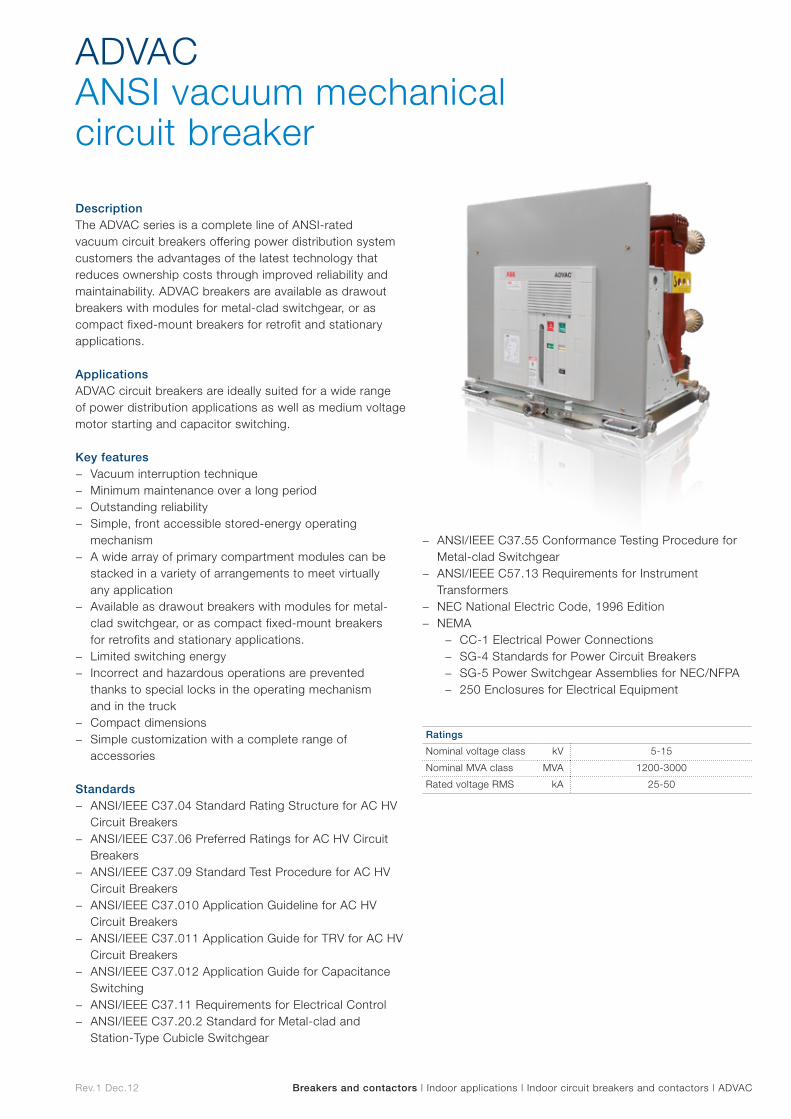
ADVAC ANSI vacuum mechanical circuit breaker
Breakers and contactors | Indoor applications | Indoor circuit breakers and contactors | ADVAC
DescriptionThe ADVAC series is a complete line of ANSI-rated vacuum circuit breakers offering power distribution system customers the advantages of the latest technology that reduces ownership costs through improved reliability and maintainability. ADVAC breakers are available as drawout breakers with modules for metal-clad switchgear, or as compact fixed-mount breakers for retrofit and stationary applications.
ApplicationsADVAC circuit breakers are ideally suited for a wide range of power distribution applications as well as medium voltage motor starting and capacitor switching.
Key features − Vacuum interruption technique − Minimum maintenance over a long period − Outstanding reliability − Simple, front accessible stored-energy operating
mechanism − A wide array of primary compartment modules can be
stacked in a variety of arrangements to meet virtually any application
− Available as drawout breakers with modules for metal-clad switchgear, or as compact fixed-mount breakers for retrofits and stationary applications.
− Limited switching energy − Incorrect and hazardous operations are prevented
thanks to special locks in the operating mechanism and in the truck
− Compact dimensions − Simple customization with a complete range of
accessories
Standards − ANSI/IEEE C37.04 Standard Rating Structure for AC HV
Circuit Breakers − ANSI/IEEE C37.06 Preferred Ratings for AC HV Circuit
Breakers − ANSI/IEEE C37.09 Standard Test Procedure for AC HV
Circuit Breakers − ANSI/IEEE C37.010 Application Guideline for AC HV
Circuit Breakers − ANSI/IEEE C37.011 Application Guide for TRV for AC HV
Circuit Breakers − ANSI/IEEE C37.012 Application Guide for Capacitance
Switching − ANSI/IEEE C37.11 Requirements for Electrical Control − ANSI/IEEE C37.20.2 Standard for Metal-clad and
Station-Type Cubicle Switchgear
− ANSI/IEEE C37.55 Conformance Testing Procedure for Metal-clad Switchgear
− ANSI/IEEE C57.13 Requirements for Instrument Transformers
− NEC National Electric Code, 1996 Edition − NEMA
− CC-1 Electrical Power Connections − SG-4 Standards for Power Circuit Breakers − SG-5 Power Switchgear Assemblies for NEC/NFPA − 250 Enclosures for Electrical Equipment
Ratings
Nominal voltage class kV 5-15
Nominal MVA class MVA 1200-3000
Rated voltage RMS kA 25-50
Rev.1 Dec.12
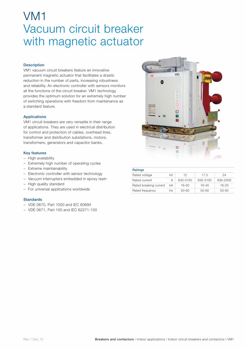
VM1Vacuum circuit breaker with magnetic actuator
Breakers and contactors | Indoor applications | Indoor circuit breakers and contactors | VM1
DescriptionVM1 vacuum circuit breakers feature an innovative permanent magnetic actuator that facilitates a drastic reduction in the number of parts, increasing robustness and reliability. An electronic controller with sensors monitors all the functions of the circuit breaker. VM1 technology provides the optimum solution for an extremely high number of switching operations with freedom from maintenance as a standard feature.
ApplicationsVM1 circuit breakers are very versatile in their range of applications. They are used in electrical distribution for control and protection of cables, overhead lines, transformer and distribution substations, motors, transformers, generators and capacitor banks.
Key features − High availability − Extremely high number of operating cycles − Extreme maintainability − Electronic controller with sensor technology − Vacuum interrupters embedded in epoxy resin − High quality standard − For universal applications worldwide
Standards − VDE 0670, Part 1000 and IEC 60694 − VDE 0671, Part 100 and IEC 62271-100
Ratings
Rated voltage kV 12 17.5 24
Rated current A 630-3150 630-3150 630-2500
Rated breaking current kA 16-50 16-40 16-25
Rated frequency Hz 50-60 50-60 50-60
Rev.1 Dec.12 Breakers and contactors | Indoor applications | Indoor circuit breakers and contactors | AMVAC
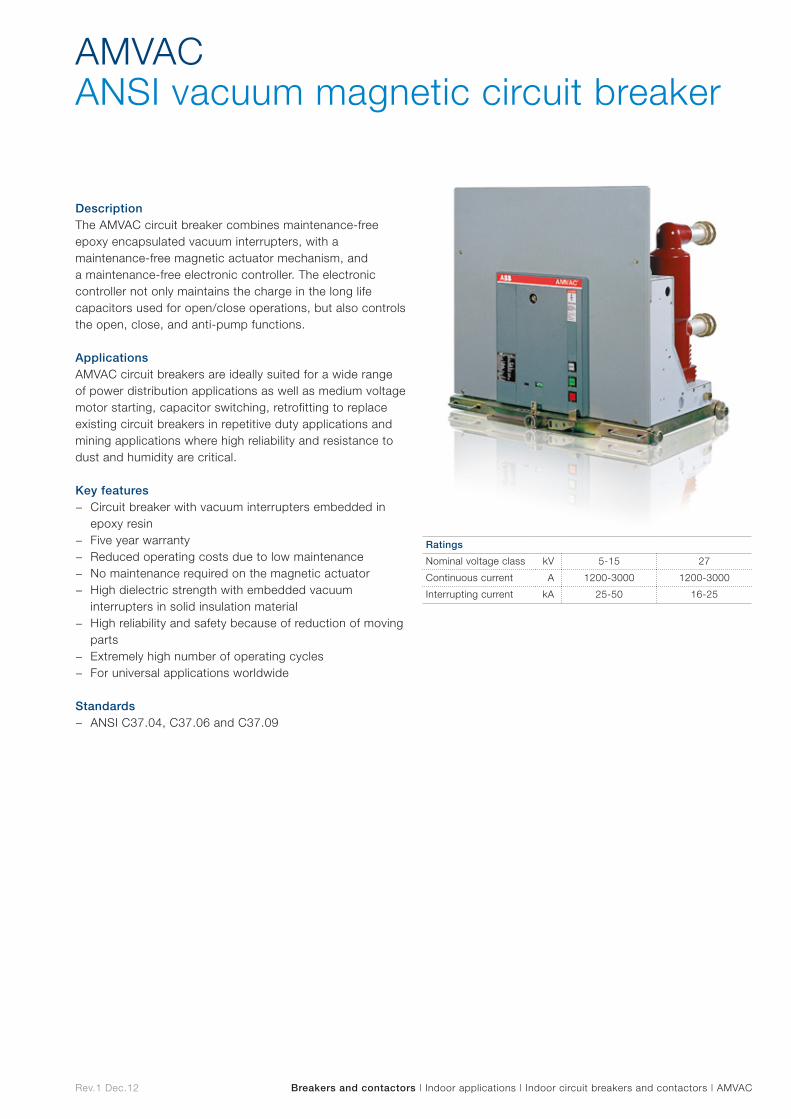
AMVAC ANSI vacuum magnetic circuit breaker
DescriptionThe AMVAC circuit breaker combines maintenance-free epoxy encapsulated vacuum interrupters, with a maintenance-free magnetic actuator mechanism, and a maintenance-free electronic controller. The electronic controller not only maintains the charge in the long life capacitors used for open/close operations, but also controls the open, close, and anti-pump functions.
ApplicationsAMVAC circuit breakers are ideally suited for a wide range of power distribution applications as well as medium voltage motor starting, capacitor switching, retrofitting to replace existing circuit breakers in repetitive duty applications and mining applications where high reliability and resistance to dust and humidity are critical.
Key features − Circuit breaker with vacuum interrupters embedded in
epoxy resin − Five year warranty − Reduced operating costs due to low maintenance − No maintenance required on the magnetic actuator − High dielectric strength with embedded vacuum
interrupters in solid insulation material − High reliability and safety because of reduction of moving
parts − Extremely high number of operating cycles − For universal applications worldwide
Standards − ANSI C37.04, C37.06 and C37.09
Ratings
Nominal voltage class kV 5-15 27
Continuous current A 1200-3000 1200-3000
Interrupting current kA 25-50 16-25
Rev.1 Dec.12
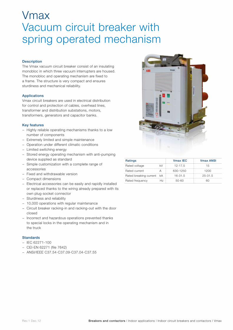
VmaxVacuum circuit breaker with spring operated mechanism
Breakers and contactors | Indoor applications | Indoor circuit breakers and contactors | Vmax
DescriptionThe Vmax vacuum circuit breaker consist of an insulating monobloc in which three vacuum interrupters are housed. The monobloc and operating mechanism are fixed to a frame. The structure is very compact and ensures sturdiness and mechanical reliability.
ApplicationsVmax circuit breakers are used in electrical distribution for control and protection of cables, overhead lines, transformer and distribution substations, motors, transformers, generators and capacitor banks.
Key features − Highly reliable operating mechanisms thanks to a low
number of components − Extremely limited and simple maintenance − Operation under different climatic conditions − Limited switching energy − Stored energy operating mechanism with anti-pumping
device supplied as standard − Simple customization with a complete range of
accessories − Fixed and withdrawable version − Compact dimensions − Electrical accessories can be easily and rapidly installed
or replaced thanks to the wiring already prepared with its own plug-socket connector
− Sturdiness and reliability − 10,000 operations with regular maintenance − Circuit breaker racking-in and racking-out with the door
closed − Incorrect and hazardous operations prevented thanks
to special locks in the operating mechanism and in the truck
Standards − IEC 62271-100 − CEI-EN 62271 (file 7642) − ANSI/IEEE C37.54-C37.09-C37.04-C37.55
Ratings Vmax IEC Vmax ANSI
Rated voltage kV 12-17.5 15
Rated current A 630-1250 1200
Rated breaking current kA 16-31.5 25-31.5
Rated frequency Hz 50-60 60

Rev.1 Dec.12
VSC Vacuum contactor with magnetic actuator
Breakers and contactors | Indoor applications | Indoor circuit breakers and contactors | VSC
DescriptionVSC medium voltage contactors are designed for AC applications in installations requiring a high number of hourly operations. The VSC features a permanent magnetic actuator which is already well proven on medium voltage circuit breakers.
VSC contactors are available in a fixed version with the following functions: Single Command Operated – electrical latching and Double Command Operated – mechanical latching.
ApplicationsVSC contactors are used for controlling electrical apparatus in industry and in the service sector Thanks to the vacuum interrupter breaking technique, the contactors can operate in particularly difficult environments. They are suitable for control and protection of motors, transformers, power factor correction banks, switching systems, etc. Fitted with suitable fuses, they can be used in circuits with fault levels up to 1000 MVA.
Key features − Maintenance-free − High number of operations − Long electrical and mechanical life − Use in Slimline Motor Control Center switchgear possible − Suitable for traditional type switchgear solutions − High reliability because of bi-stable magnetic actuator − Limited power consumption therefore reduced
environmental impact Standards
− IEC 60470 (2000) Standards
Ratings
Rated voltage kV 7.2 12
Rated current A 400 400
Breaking capacity A 4000 4000
Short time withst. Current 1s A 6000 6000
Rev.1 Dec.12
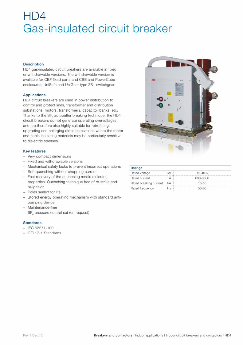
HD4Gas-insulated circuit breaker
Breakers and contactors | Indoor applications | Indoor circuit breakers and contactors | HD4
DescriptionHD4 gas-insulated circuit breakers are available in fixed or withdrawable versions. The withdrawable version is available for CBF fixed parts and CBE and PowerCube enclosures, UniSafe and UniGear type ZS1 switchgear.
ApplicationsHD4 circuit breakers are used in power distribution to control and protect lines, transformer and distribution substations, motors, transformers, capacitor banks, etc. Thanks to the SF6 autopuffer breaking technique, the HD4 circuit breakers do not generate operating overvoltages, and are therefore also highly suitable for retrofitting, upgrading and enlarging older installations where the motor and cable insulating materials may be particularly sensitive to dielectric stresses.
Key features − Very compact dimensions − Fixed and withdrawable versions − Mechanical safety locks to prevent incorrect operations − Soft quenching without chopping current − Fast recovery of the quenching media dielectric
properties. Quenching technique free of re-strike and re-ignition
− Poles sealed for life − Stored energy operating mechanism with standard anti-
pumping device − Maintenance-free − SF6 pressure control set (on request)
Standards − IEC 62271-100 − CEI 17-1 Standards
Ratings
Rated voltage kV 12-40.5
Rated current A 630-3600
Rated breaking current kA 16-50
Rated frequency Hz 50-60
Rev.1 Dec.12
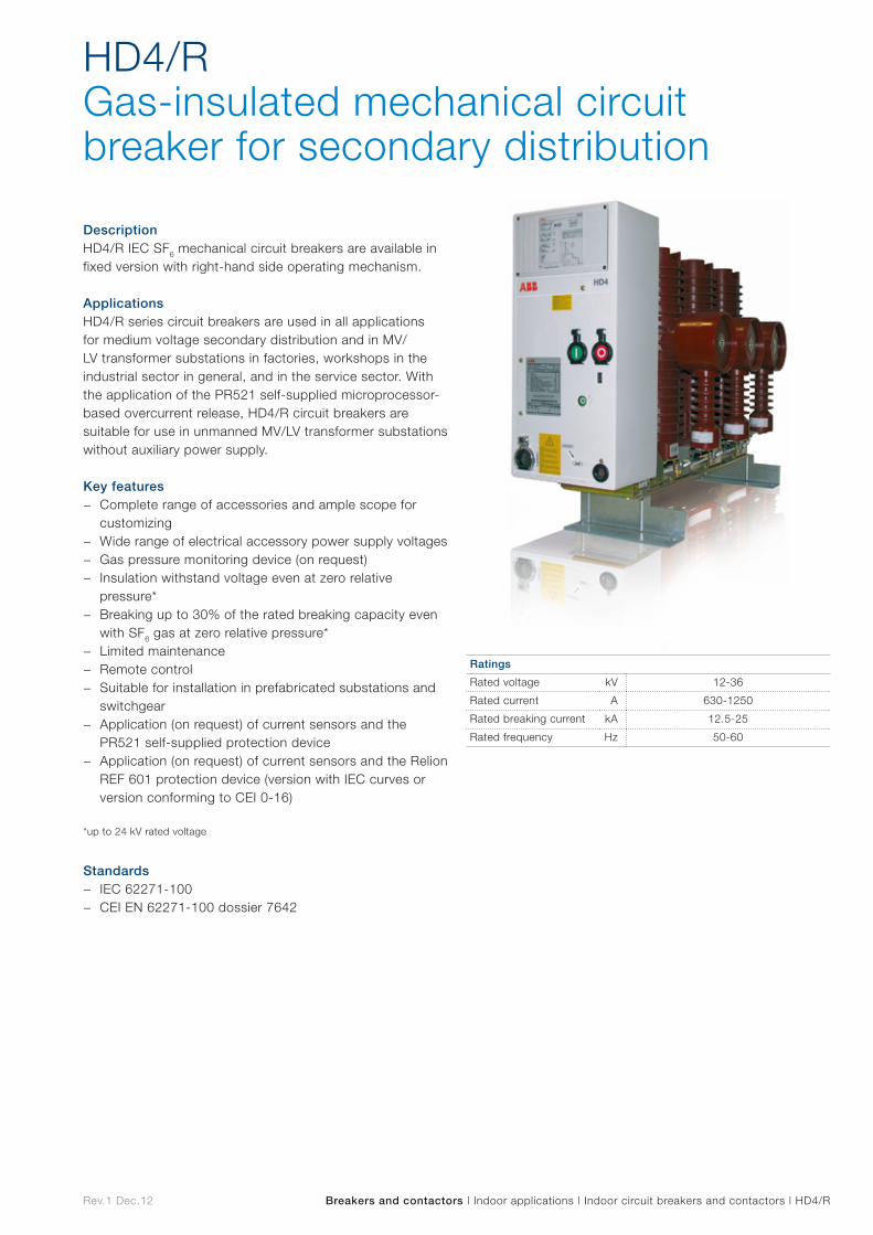
HD4/R Gas-insulated mechanical circuit breaker for secondary distribution
Breakers and contactors | Indoor applications | Indoor circuit breakers and contactors | HD4/R
DescriptionHD4/R IEC SF6 mechanical circuit breakers are available in fixed version with right-hand side operating mechanism.
ApplicationsHD4/R series circuit breakers are used in all applications for medium voltage secondary distribution and in MV/LV transformer substations in factories, workshops in the industrial sector in general, and in the service sector. With the application of the PR521 self-supplied microprocessor-based overcurrent release, HD4/R circuit breakers are suitable for use in unmanned MV/LV transformer substations without auxiliary power supply.
Key features − Complete range of accessories and ample scope for
customizing − Wide range of electrical accessory power supply voltages − Gas pressure monitoring device (on request) − Insulation withstand voltage even at zero relative
pressure* − Breaking up to 30% of the rated breaking capacity even
with SF6 gas at zero relative pressure* − Limited maintenance − Remote control − Suitable for installation in prefabricated substations and
switchgear − Application (on request) of current sensors and the
PR521 self-supplied protection device − Application (on request) of current sensors and the Relion
REF 601 protection device (version with IEC curves or version conforming to CEI 0-16)
*up to 24 kV rated voltage
Standards − IEC 62271-100 − CEI EN 62271-100 dossier 7642
Ratings
Rated voltage kV 12-36
Rated current A 630-1250
Rated breaking current kA 12.5-25
Rated frequency Hz 50-60
Rev.1 Dec.12
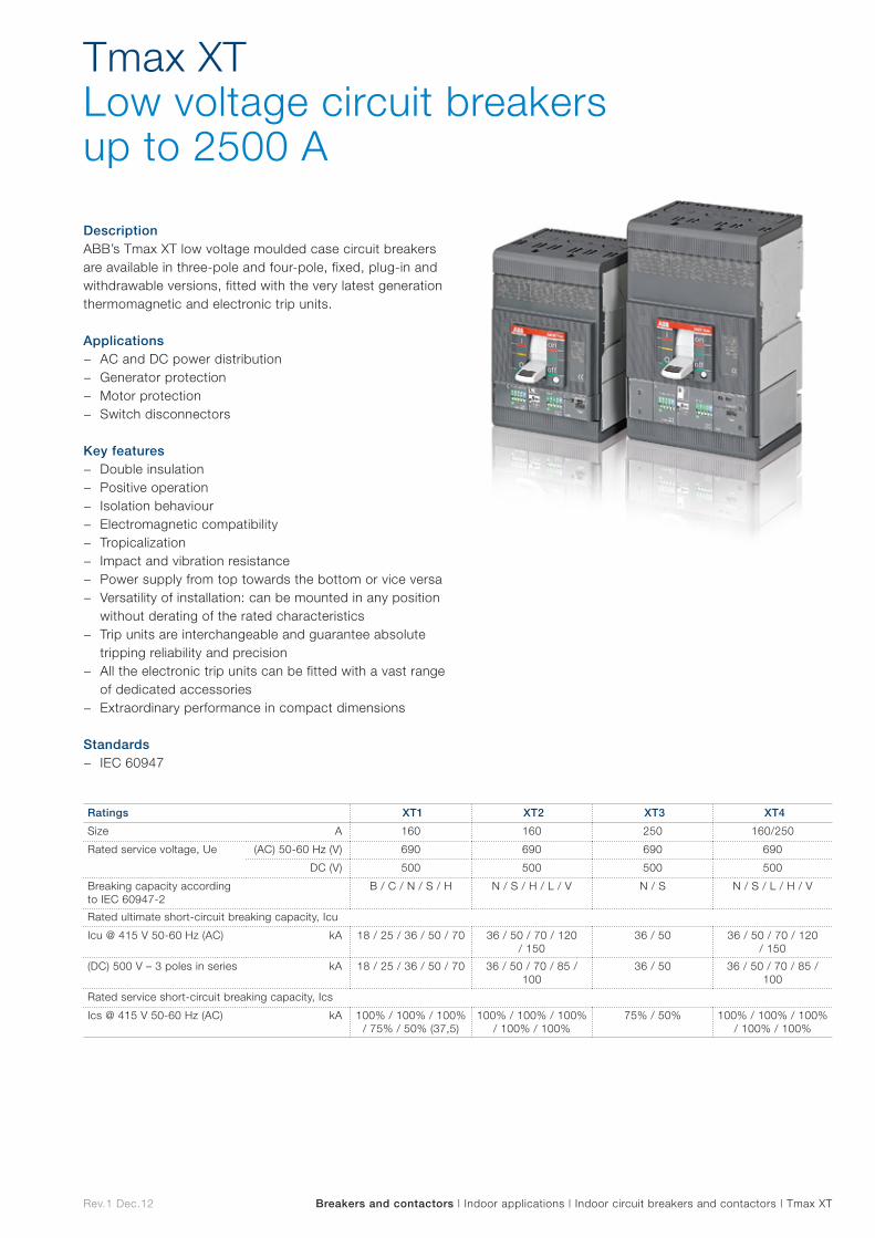
Tmax XT Low voltage circuit breakers up to 2500 A
Breakers and contactors | Indoor applications | Indoor circuit breakers and contactors | Tmax XT
DescriptionABB’s Tmax XT low voltage moulded case circuit breakers are available in three-pole and four-pole, fixed, plug-in and withdrawable versions, fitted with the very latest generation thermomagnetic and electronic trip units.
Applications − AC and DC power distribution − Generator protection − Motor protection − Switch disconnectors
Key features − Double insulation − Positive operation − Isolation behaviour − Electromagnetic compatibility − Tropicalization − Impact and vibration resistance − Power supply from top towards the bottom or vice versa − Versatility of installation: can be mounted in any position
without derating of the rated characteristics − Trip units are interchangeable and guarantee absolute
tripping reliability and precision − All the electronic trip units can be fitted with a vast range
of dedicated accessories − Extraordinary performance in compact dimensions
Standards − IEC 60947
Ratings XT1 XT2 XT3 XT4
Size A 160 160 250 160/250
Rated service voltage, Ue (AC) 50-60 Hz (V) 690 690 690 690
DC (V) 500 500 500 500
Breaking capacity according to IEC 60947-2
B / C / N / S / H N / S / H / L / V N / S N / S / L / H / V
Rated ultimate short-circuit breaking capacity, Icu
Icu @ 415 V 50-60 Hz (AC) kA 18 / 25 / 36 / 50 / 70 36 / 50 / 70 / 120 / 150
36 / 50 36 / 50 / 70 / 120 / 150
(DC) 500 V – 3 poles in series kA 18 / 25 / 36 / 50 / 70 36 / 50 / 70 / 85 / 100
36 / 50 36 / 50 / 70 / 85 / 100
Rated service short-circuit breaking capacity, Ics
Ics @ 415 V 50-60 Hz (AC) kA 100% / 100% / 100% / 75% / 50% (37,5)
100% / 100% / 100% / 100% / 100%
75% / 50% 100% / 100% / 100% / 100% / 100%
Rev.1 Dec.12 Breakers and contactors | Indoor applications | Indoor circuit breakers and contactors | Tmax
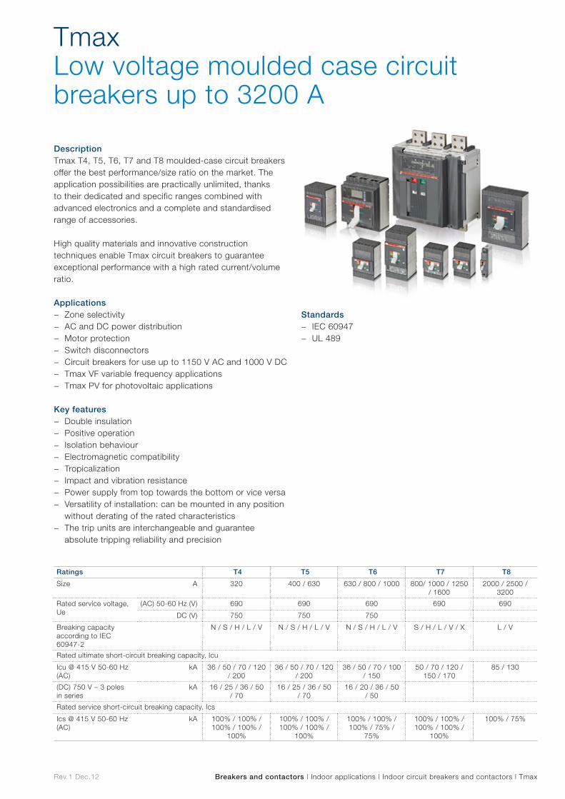
Tmax Low voltage moulded case circuit breakers up to 3200 A
DescriptionTmax T4, T5, T6, T7 and T8 moulded-case circuit breakers offer the best performance/size ratio on the market. The application possibilities are practically unlimited, thanks to their dedicated and specific ranges combined with advanced electronics and a complete and standardised range of accessories.
High quality materials and innovative construction techniques enable Tmax circuit breakers to guarantee exceptional performance with a high rated current/volume ratio.
Applications − Zone selectivity − AC and DC power distribution − Motor protection − Switch disconnectors − Circuit breakers for use up to 1150 V AC and 1000 V DC − Tmax VF variable frequency applications − Tmax PV for photovoltaic applications
Key features − Double insulation − Positive operation − Isolation behaviour − Electromagnetic compatibility − Tropicalization − Impact and vibration resistance − Power supply from top towards the bottom or vice versa − Versatility of installation: can be mounted in any position
without derating of the rated characteristics − The trip units are interchangeable and guarantee
absolute tripping reliability and precision
Standards − IEC 60947 − UL 489
Ratings T4 T5 T6 T7 T8
Size A 320 400 / 630 630 / 800 / 1000 800/ 1000 / 1250 / 1600
2000 / 2500 / 3200
Rated service voltage, Ue
(AC) 50-60 Hz (V) 690 690 690 690 690
DC (V) 750 750 750
Breaking capacity according to IEC 60947-2
N / S / H / L / V N / S / H / L / V N / S / H / L / V S / H / L / V / X L / V
Rated ultimate short-circuit breaking capacity, Icu
Icu @ 415 V 50-60 Hz (AC)
kA 36 / 50 / 70 / 120 / 200
36 / 50 / 70 / 120 / 200
36 / 50 / 70 / 100 / 150
50 / 70 / 120 / 150 / 170
85 / 130
(DC) 750 V – 3 poles in series
kA 16 / 25 / 36 / 50 / 70
16 / 25 / 36 / 50 / 70
16 / 20 / 36 / 50 / 50
Rated service short-circuit breaking capacity, Ics
Ics @ 415 V 50-60 Hz (AC)
kA 100% / 100% / 100% / 100% /
100%
100% / 100% / 100% / 100% /
100%
100% / 100% / 100% / 75% /
75%
100% / 100% / 100% / 100% /
100%
100% / 75%
Rev.1 Dec.12
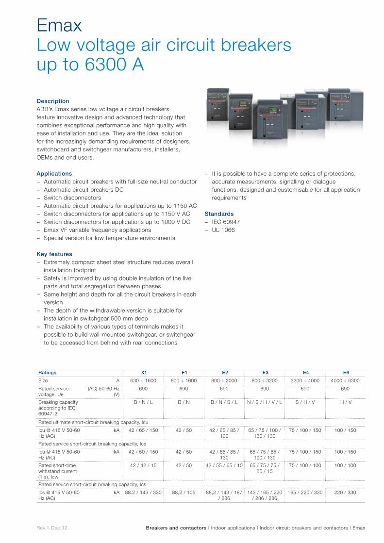
Emax Low voltage air circuit breakers up to 6300 A
Breakers and contactors | Indoor applications | Indoor circuit breakers and contactors | Emax
DescriptionABB’s Emax series low voltage air circuit breakers feature innovative design and advanced technology that combines exceptional performance and high quality with ease of installation and use. They are the ideal solution for the increasingly demanding requirements of designers, switchboard and switchgear manufacturers, installers, OEMs and end users.
Applications − Automatic circuit breakers with full-size neutral conductor − Automatic circuit breakers DC − Switch disconnectors − Automatic circuit breakers for applications up to 1150 AC − Switch disconnectors for applications up to 1150 V AC − Switch disconnectors for applications up to 1000 V DC − Emax VF variable frequency applications − Special version for low temperature environments
Key features − Extremely compact sheet steel structure reduces overall
installation footprint − Safety is improved by using double insulation of the live
parts and total segregation between phases − Same height and depth for all the circuit breakers in each
version − The depth of the withdrawable version is suitable for
installation in switchgear 500 mm deep − The availability of various types of terminals makes it
possible to build wall-mounted switchgear, or switchgear to be accessed from behind with rear connections
− It is possible to have a complete series of protections, accurate measurements, signalling or dialogue functions, designed and customisable for all application requirements
Standards − IEC 60947 − UL 1066
Ratings X1 E1 E2 E3 E4 E6
Size A 630 ÷ 1600 800 ÷ 1600 800 ÷ 2000 800 ÷ 3200 3200 ÷ 4000 4000 ÷ 6300
Rated service voltage, Ue
(AC) 50-60 Hz (V)
690 690 690 690 690 690
Breaking capacity according to IEC 60947-2
B / N / L B / N B / N / S / L N / S / H / V / L S / H / V H / V
Rated ultimate short-circuit breaking capacity, Icu
Icu @ 415 V 50-60 Hz (AC)
kA 42 / 65 / 150 42 / 50 42 / 65 / 85 / 130
65 / 75 / 100 / 130 / 130
75 / 100 / 150 100 / 150
Rated service short-circuit breaking capacity, Ics
Icu @ 415 V 50-60 Hz (AC)
kA 42 / 50 / 150 42 / 50 42 / 65 / 85 / 130
65 / 75 / 85 / 100 / 130
75 / 100 / 150 100 / 150
Rated short-time withstand current (1 s), Icw
42 / 42 / 15 42 / 50 42 / 55 / 65 / 10 65 / 75 / 75 / 85 / 15
75 / 100 / 100 100 / 100
Rated service short-circuit breaking capacity, Ics
Ics @ 415 V 50-60 Hz (AC)
kA 88.2 / 143 / 330 88,2 / 105 88,2 / 143 / 187 / 286
143 / 165 / 220 / 286 / 286
165 / 220 / 330 220 / 330

Outdoor applications Outd
oo
r ap
plicatio
ns
Rev.1 Dec.12
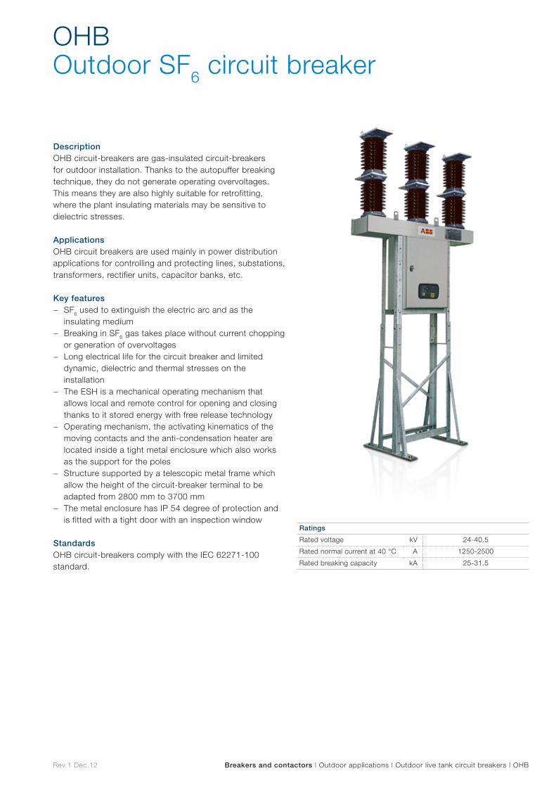
OHB Outdoor SF6 circuit breaker
Breakers and contactors | Outdoor applications | Outdoor live tank circuit breakers | OHB
DescriptionOHB circuit-breakers are gas-insulated circuit-breakers for outdoor installation. Thanks to the autopuffer breaking technique, they do not generate operating overvoltages. This means they are also highly suitable for retrofitting, where the plant insulating materials may be sensitive to dielectric stresses.
ApplicationsOHB circuit breakers are used mainly in power distribution applications for controlling and protecting lines, substations, transformers, rectifier units, capacitor banks, etc.
Key features − SF6 used to extinguish the electric arc and as the
insulating medium − Breaking in SF6 gas takes place without current chopping
or generation of overvoltages − Long electrical life for the circuit breaker and limited
dynamic, dielectric and thermal stresses on the installation
− The ESH is a mechanical operating mechanism that allows local and remote control for opening and closing thanks to it stored energy with free release technology
− Operating mechanism, the activating kinematics of the moving contacts and the anti-condensation heater are located inside a tight metal enclosure which also works as the support for the poles
− Structure supported by a telescopic metal frame which allow the height of the circuit-breaker terminal to be adapted from 2800 mm to 3700 mm
− The metal enclosure has IP 54 degree of protection and is fitted with a tight door with an inspection window
StandardsOHB circuit-breakers comply with the IEC 62271-100 standard.
Ratings
Rated voltage kV 24-40.5
Rated normal current at 40 °C A 1250-2500
Rated breaking capacity kA 25-31.5
Rev.1 Dec.12
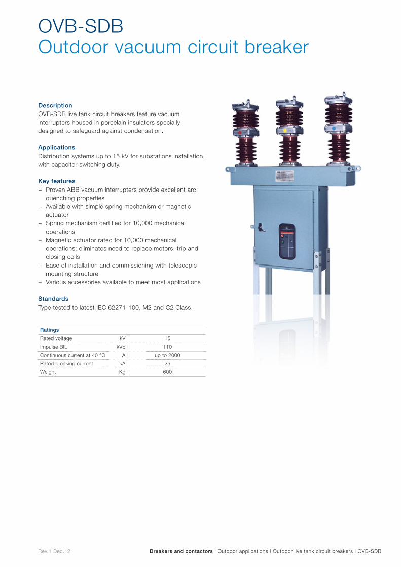
OVB-SDB Outdoor vacuum circuit breaker
Breakers and contactors | Outdoor applications | Outdoor live tank circuit breakers | OVB-SDB
DescriptionOVB-SDB live tank circuit breakers feature vacuum interrupters housed in porcelain insulators specially designed to safeguard against condensation.
ApplicationsDistribution systems up to 15 kV for substations installation, with capacitor switching duty.
Key features − Proven ABB vacuum interrupters provide excellent arc
quenching properties − Available with simple spring mechanism or magnetic
actuator − Spring mechanism certified for 10,000 mechanical
operations − Magnetic actuator rated for 10,000 mechanical
operations: eliminates need to replace motors, trip and closing coils
− Ease of installation and commissioning with telescopic mounting structure
− Various accessories available to meet most applications
StandardsType tested to latest IEC 62271-100, M2 and C2 Class.
Ratings
Rated voltage kV 15
Impulse BIL kVp 110
Continuous current at 40 °C A up to 2000
Rated breaking current kA 25
Weight Kg 600
Rev.1 Dec.12 Breakers and contactors | Outdoor applications | Outdoor live tank circuit breakers | OVB-VBF
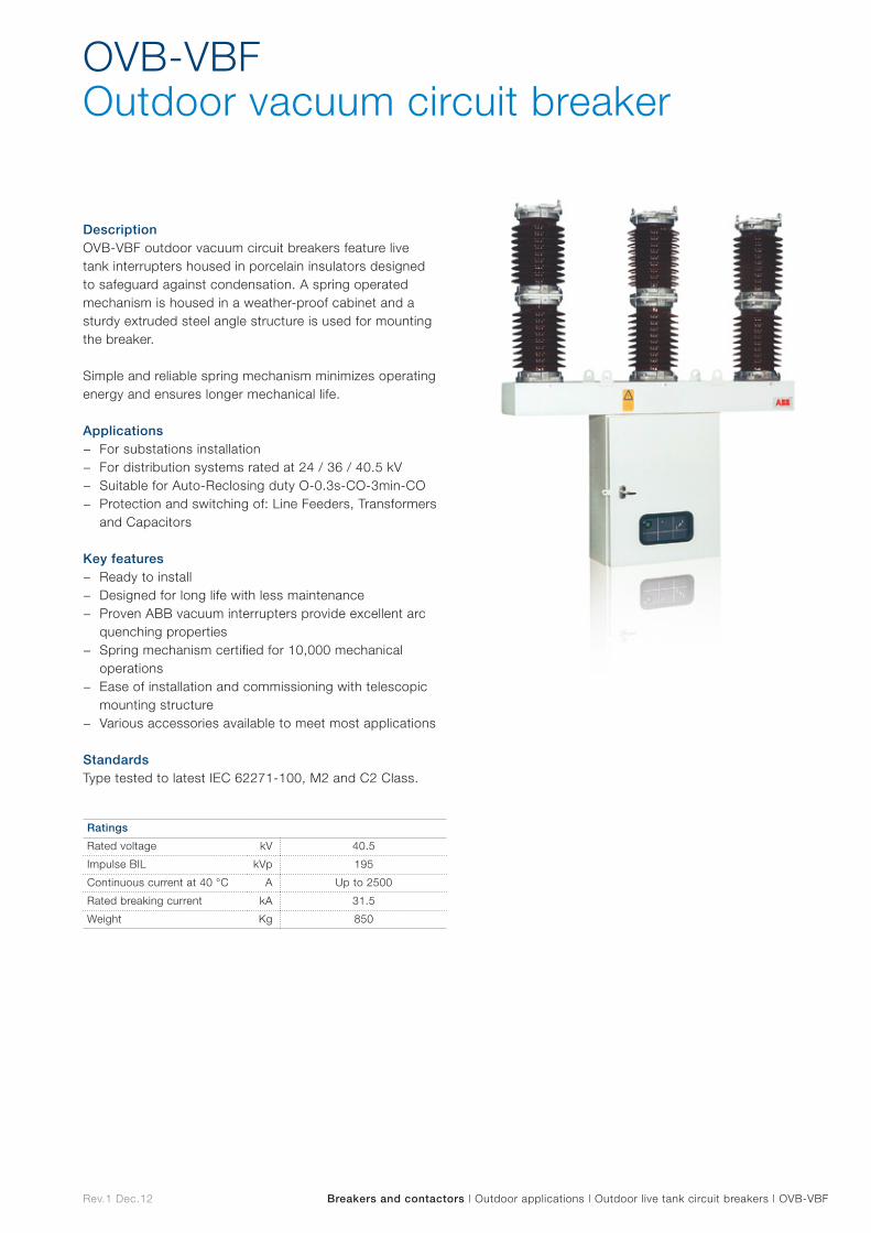
OVB-VBFOutdoor vacuum circuit breaker
DescriptionOVB-VBF outdoor vacuum circuit breakers feature live tank interrupters housed in porcelain insulators designed to safeguard against condensation. A spring operated mechanism is housed in a weather-proof cabinet and a sturdy extruded steel angle structure is used for mounting the breaker.
Simple and reliable spring mechanism minimizes operating energy and ensures longer mechanical life.
Applications − For substations installation − For distribution systems rated at 24 / 36 / 40.5 kV − Suitable for Auto-Reclosing duty O-0.3s-CO-3min-CO − Protection and switching of: Line Feeders, Transformers
and Capacitors
Key features − Ready to install − Designed for long life with less maintenance − Proven ABB vacuum interrupters provide excellent arc
quenching properties − Spring mechanism certified for 10,000 mechanical
operations − Ease of installation and commissioning with telescopic
mounting structure − Various accessories available to meet most applications
StandardsType tested to latest IEC 62271-100, M2 and C2 Class.
Ratings
Rated voltage kV 40.5
Impulse BIL kVp 195
Continuous current at 40 °C A Up to 2500
Rated breaking current kA 31.5
Weight Kg 850
Rev.1 Dec.12
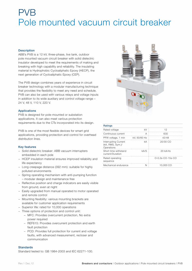
PVB Pole mounted vacuum circuit breaker
Breakers and contactors | Outdoor applications | Pole mounted circuit breakers | PVB
DescriptionABB’s PVB is a 12 kV, three-phase, live tank, outdoor pole mounted vacuum circuit breaker with solid dielectric insulator developed to meet the requirements of making and breaking with high capability and reliability. The insulating material is Hydrophobic Cycloaliphatic Epoxy (HECP), the next generation of Cycloaliphatic Epoxy (CEP).
The PVB design combines years of experience in circuit breaker technology with a modular manufacturing technique that provides the flexibility to meet any need and schedule. PVB can also be used with various relays and voltage inputs in addition to its wide auxiliary and control voltage range – 24 V, 48 V, 110 V, 220 V.
ApplicationsPVB is designed for pole-mounted or substation applications. It can also meet various protection requirements due to the CTs incorporated into its design.
PVB is one of the most flexible devices for smart grid applications, providing protection and control for overhead distribution lines.
Key features − Solid dielectric breaker: ABB vacuum interrupters
embedded in each pole − HCEP insulation material ensures improved reliability and
life expectancy − Long creepage distance (392 mm): suitable for highly
polluted environments − Spring operating mechanism with anti-pumping function
– modular design and maintenance free − Reflective position and charge indicators are easily visible
from ground, even at night − Easily upgraded from manual operated to motor operated
and remote control − Mounting flexibility: various mounting brackets are
available for customer application requirements − Superior life: rated for 10,000 operations − Three options of protection and control unit:
− MFC: Provides overcurrent protection, No extra power required
− REF615: Provides overcurrent protection and earth fault protection
− PCD: Provides full protection for current and voltage faults, with advanced measurement, recloser and communication
StandardsStandard tested to: GB 1984-2003 and IEC 62271-100.
Ratings
Rated voltage kV 12
Continuous current A 630
PFW voltage, 1 min kV, 50/60 Hz 42/48
Interrupting Current (kA, RMS, Sym.)/Operations
kA 20/30 CO
Short time withstand current/Duration
kA/S 20 kA/4s
Rated operating sequence
O-0.3s-CO-15s-CO
Mechanical endurance N 10,000 CO
Rev.1 Dec.12 Breakers and contactors | Outdoor applications | Padmount circuit breakers | ReliaPad
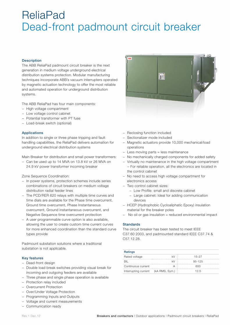
DescriptionThe ABB ReliaPad padmount circuit breaker is the next generation in medium voltage underground electrical distribution systems protection. Modular manufacturing techniques incorporate ABB’s vacuum interrupters operated by magnetic actuation technology to offer the most reliable and automated operation for underground distribution systems.
The ABB ReliaPad has four main components: − High voltage compartment − Low voltage control cabinet − Potential transformer with PT fuse − Load-break switch (optional)
ApplicationsIn addition to single or three phase tripping and fault handling capabilities, the ReliaPad delivers automation for underground electrical distribution systems
Main Breaker for distribution and small power transformers: − Can be used up to 14 MVA on 13.8 kV or 26 MVA on
24.9 kV power transformer incoming breaker
Zone Sequence Coordination: − In power systems, protection schemes include series
combinations of circuit breakers on medium voltage distribution radial feeder lines
− The PCD/RER 620 relays with multiple time curves and time dials are available for the Phase time overcurrent, Ground time overcurrent, Phase Instantaneous overcurrent, Ground instantaneous overcurrent, and Negative Sequence time overcurrent protection
− A user programmable curve option is also available, allowing the user to create custom time current curves for more enhanced coordination than the standard curve types provide
Padmount substation solutions where a traditional substation is not applicable.
Key features − Dead-front design − Double load break switches providing visual break for
incoming and outgoing feeders are available − Three phase and single phase operation is available − Protection relay included − Overcurrent Protection − Over/Under Voltage Protection − Programming Inputs and Outputs − Voltage and current measurements − Communication ready
− Reclosing function included − Sectionalizer mode included − Magnetic actuators provide 10,000 mechanical/load
operations − Less moving parts = less maintenance − No mechanically charged components for added safety − Virtually no maintenance in the high voltage compartment
− For reliable operation, all the electronics are located in the control cabinet
− No need to access high voltage compartment for electronics access
− Two control cabinet sizes: − Low Profile: small and discrete cabinet − Large cabinet: Ideal for adding communication
devices − HCEP (Hydrophobic Cycloaliphatic Epoxy) insulation
material for the breaker poles − No oil or gas insulation = reduced environmental impact
StandardsThe circuit breaker has been tested to meet IEEE C37.60 2003, and padmounted standard IEEE C37.74 & C57.12.28.
ReliaPad Dead-front padmount circuit breaker
Ratings
Rated voltage kV 15-27
BIL kV 95-125
Continuous current A 600
Interrupting current (kA RMS, Sym.) 12.5
Rev.1 Dec.12 Breakers and contactors | Outdoor applications | Padmount circuit breakers | VersaPad™
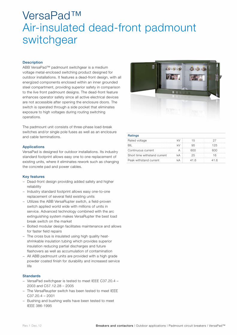
VersaPad™ Air-insulated dead-front padmount switchgear
DescriptionABB VersaPad™ padmount switchgear is a medium voltage metal-enclosed switching product designed for outdoor installations. It features a dead-front design, with all energized components enclosed within an inner grounded steel compartment, providing superior safety in comparison to the live front padmount designs. The dead-front feature enhances operator safety since all active electrical devices are not accessible after opening the enclosure doors. The switch is operated through a side pocket that eliminates exposure to high voltages during routing switching operations.
The padmount unit consists of three-phase load-break switches and/or single pole fuses as well as an enclosure and cable terminations.
ApplicationsVersaPad is designed for outdoor installations. Its industry standard footprint allows easy one to one replacement of existing units, where it eliminates rework such as changing the concrete pad and power cables.
Key features − Dead-front design providing added safety and higher
reliability − Industry standard footprint allows easy one-to-one
replacement of several field existing units − Utilizes the ABB VersaRupter switch, a field-proven
switch applied world wide with millions of units in service. Advanced technology combined with the arc extinguishing system makes VersaRupter the best load break switch on the market
− Bolted modular design facilitates maintenance and allows for faster field repairs
− The cross bus is insulated using high quality heat-shrinkable insulation tubing which provides superior insulation reducing partial discharges and future flashovers as well as accumulation of contamination
− All ABB padmount units are provided with a high grade powder coated finish for durability and increased service life
Standards − VersaPad switchgear is tested to meet IEEE C37.20.4 –
2003 and C57.12.28 – 2005 − The VersaReupter switch has been tested to meet IEEE
C37.20.4 – 2001 − Bushing and bushing wells have been tested to meet
IEEE 386-1995
Ratings
Rated voltage kV 15 27
BIL kV 95 125
Continuous current A 600 600
Short time withstand current kA 25 16
Peak withstand current kA 41.6 41.6

Cable accessories Cab
le accesso
ries
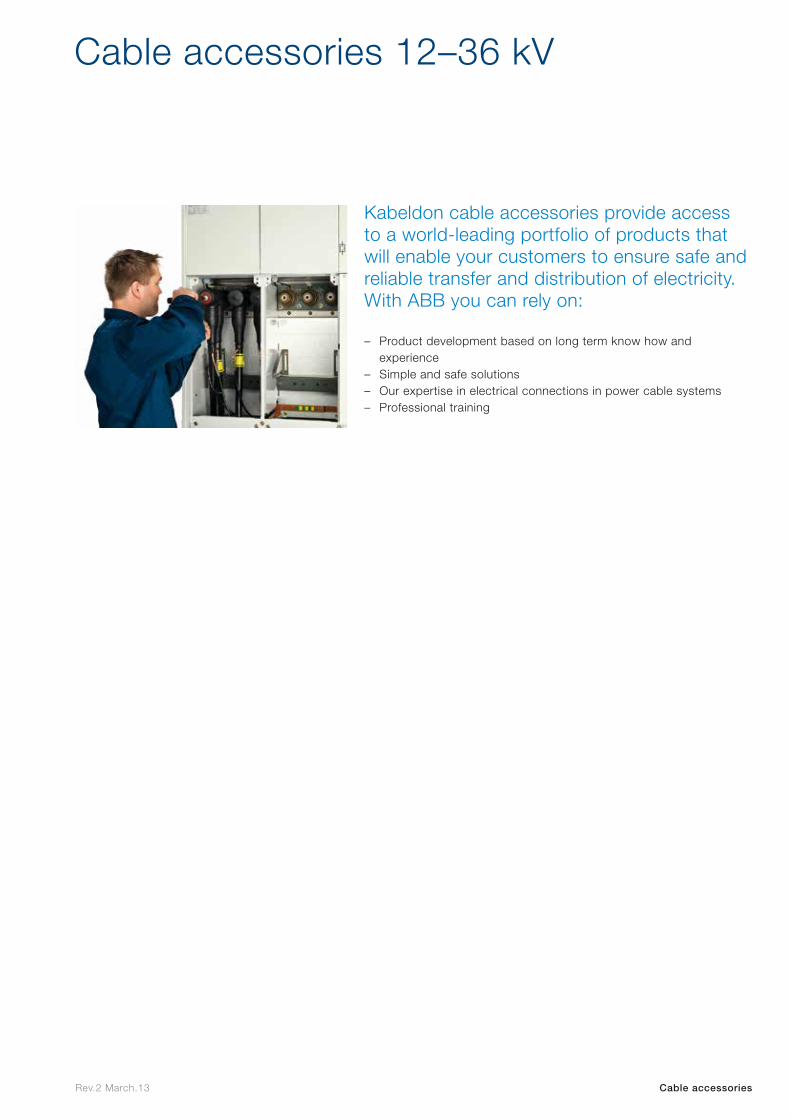
Kabeldon cable accessories provide access to a world-leading portfolio of products that will enable your customers to ensure safe and reliable transfer and distribution of electricity. With ABB you can rely on:
Cable accessories 12–36 kV
– Product development based on long term know how and experience
– Simple and safe solutions– Our expertise in electrical connections in power cable systems– Professional training
Cable accessoriesRev.2 March.13
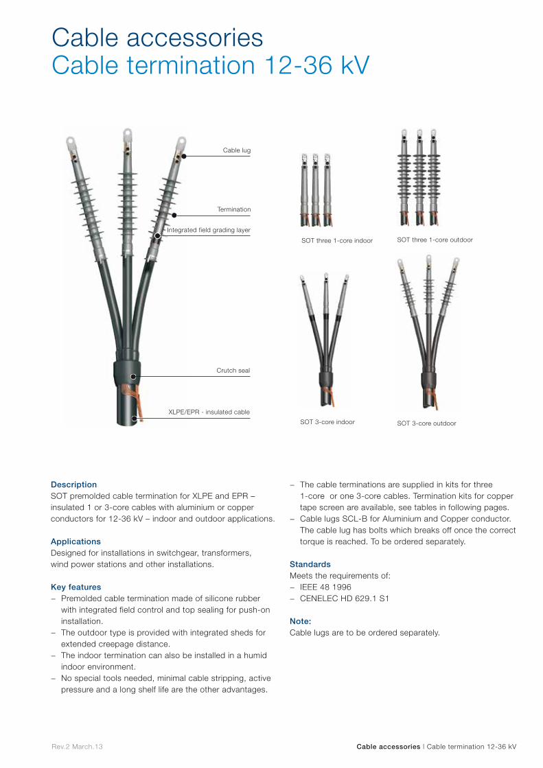
Cable accessoriesCable termination 12-36 kV
Integrated field grading layer
Crutch seal
XLPE/EPR - insulated cable
Termination
Cable lug
SOT 3-core indoor SOT 3-core outdoor
SOT three 1-core indoor SOT three 1-core outdoor
DescriptionSOT premolded cable termination for XLPE and EPR – insulated 1 or 3-core cables with aluminium or copper conductors for 12-36 kV – indoor and outdoor applications. Applications Designed for installations in switchgear, transformers, wind power stations and other installations.
Key features − Premolded cable termination made of silicone rubber
with integrated field control and top sealing for push-on installation.
− The outdoor type is provided with integrated sheds for extended creepage distance.
− The indoor termination can also be installed in a humid indoor environment.
− No special tools needed, minimal cable stripping, active pressure and a long shelf life are the other advantages.
− The cable terminations are supplied in kits for three 1-core or one 3-core cables. Termination kits for copper tape screen are available, see tables in following pages.
− Cable lugs SCL-B for Aluminium and Copper conductor.The cable lug has bolts which breaks off once the correct torque is reached. To be ordered separately.
StandardsMeets the requirements of:
− IEEE 48 1996 − CENELEC HD 629.1 S1
Note:Cable lugs are to be ordered separately.
Cable accessories | Cable termination 12-36 kV Rev.2 March.13
Indoor kits, three 1-core cables with copper-wire screenConductor
cross section
Voltage Cable
lug7.2 12 17.5 24 36
mm² Cable termination Ref. No.
10 1 4 5 4 – A
16 1 4 5 4 – A
25 1 4 5 5 – A
35 1 4 5 5 – A
50 2 5 5 5 – A
70 2 5 5 5 13 A
95 2 5 5 5 13 A
120 2 5 5 5 13 B
150 2 5 6 6 13 B
185 2 5 6 6 13 B
240 3 6 6 6 13 B
300 3 6 6 6 13 C
400 3 6 6 6 14 D
500 3 6 7 7 14 D
630 6 7 7 7 14 D
Indoor kits, 3-core cables with copper-wire screenConductor
cross section
Voltage Cable
lug7.2 12 17.5 24 36
mm² Cable termination Ref. No.
10 1 15 16 15 – A
16 1 15 16 15 – A
25 1 15 16 16 – A
35 1 15 16 16 – A
50 2 16 16 16 – A
70 2 16 17 17 13 A
95 2 16 17 17 13 A
120 2 17 17 17 13 B
150 2 17 17 18 13 B
185 2 17 17 18 13 B
240 3 18 18 18 13 B
300 3 18 18 18 13 C
400 3 18 18 18 14 D
500 3 6 7 7 14 D
630 6 7 7 7 14 D
Outdoor kits, three 1-core cables with copper-wire screenConductor
cross section
Voltage Cable
lug7.2 12 17.5 24 36
mm² Cable termination Ref. No.
10 – 8 9 9 – A
16 8 8 9 9 – A
25 8 8 9 9 – A
35 8 8 9 9 – A
50 8 9 9 9 – A
70 9 9 9 9 13 A
95 9 9 9 10 13 A
120 9 9 10 10 13 B
150 9 10 10 10 13 B
185 9 10 10 10 13 B
240 10 10 10 10 13 B
300 10 10 10 11 13 C
400 10 11 11 11 14 D
500 11 11 11 12 14 D
630 11 12 12 12 14 D
Outdoor kits, 3-core cables with copper-wire screenConductor
cross section
Voltage kV Cable
lug7.2 12 17.5 24 36
mm² Cable termination Ref. No.
10 - 19 20 19 – A
16 19 19 20 20 – A
25 19 19 20 20 – A
35 19 19 20 20 – A
50 19 20 20 20 – A
70 20 20 20 20 13 A
95 20 20 20 21 13 A
120 20 20 21 21 13 B
150 20 21 21 21 13 B
185 20 21 21 21 13 B
240 21 21 21 21 13 B
300 21 21 21 22 13 C
400 21 22 22 22 14 D
Termination kitsRef. No. Designation Ref. No. Designation
1 SOT 101-3 12 SOT 246-31
2 SOT 102-3 13 SOT 361-31
3 SOT 103-3 14 SOT 362-31
4 SOT 241A-3 15 SOT 241A-3C
5 SOT 241-3 16 SOT 241-3C
6 SOT 242-3 17 SOT 241-3D
7 SOT 242B-3 18 SOT 242-3D
8 SOT 243A-31 19 SOT 243A-3
9 SOT 243-31 20 SOT 243-3
10 SOT 244-31 21 SOT 244-3
11 SOT 245-31 22 SOT 245-3
Cable lugs*Ref. No. Designation Quantity
A SCL-B 95-12 1 pcs
B SCL-B 240-12 1 pcs
C SCL-B 300-16 1 pcs
D SCL-B 630-16 1 pcs
* Cable lugs are supplied as single items. You need three pieces for each kit of termination.
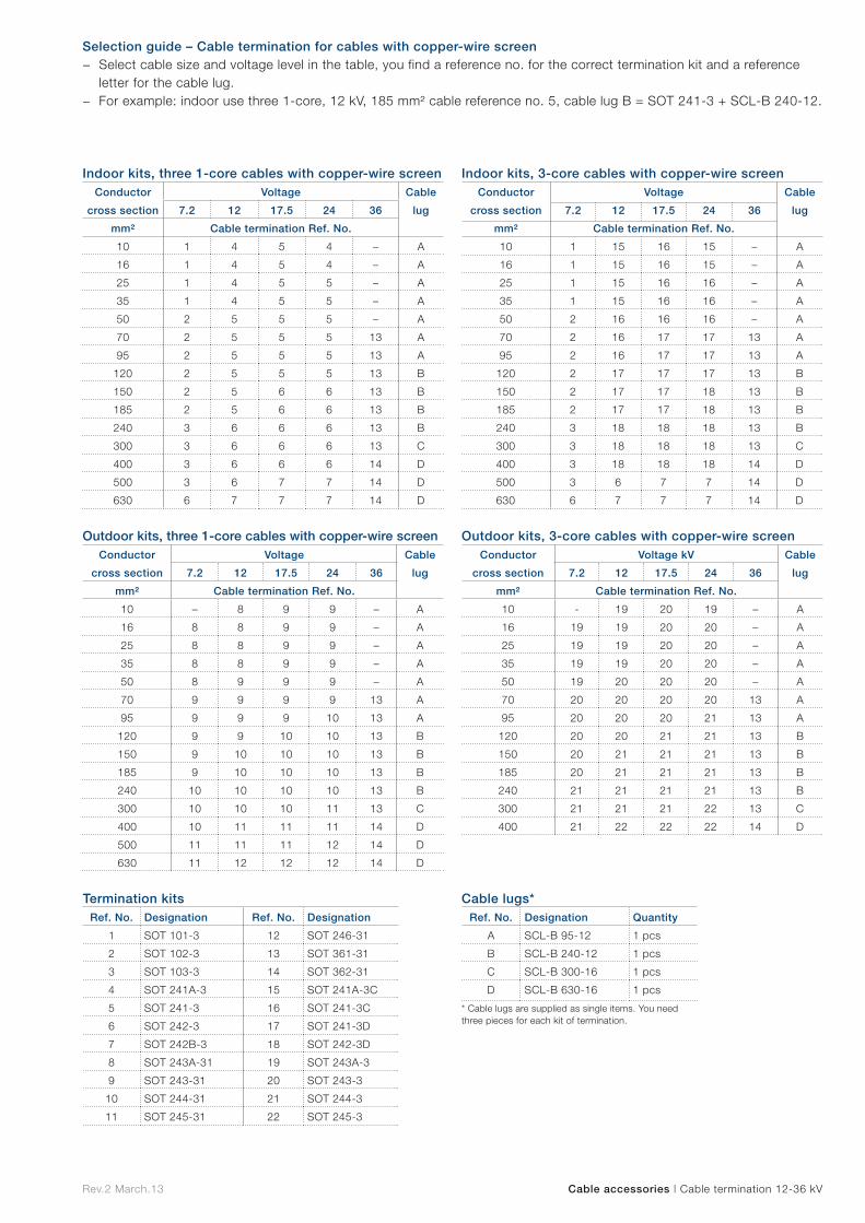
Selection guide – Cable termination for cables with copper-wire screen − Select cable size and voltage level in the table, you find a reference no. for the correct termination kit and a reference
letter for the cable lug. − For example: indoor use three 1-core, 12 kV, 185 mm² cable reference no. 5, cable lug B = SOT 241-3 + SCL-B 240-12.
Cable accessories | Cable termination 12-36 kV Rev.2 March.13

Termination kitsRef. No. Designation Ref. No. Designation Ref. No. Designation
23 SOT 101-3R 35 SOT 244-3T 47 SOT 241-3SD
24 SOT 102-3R 36 SOT 245-3T 48 SOT 242-3SD
25 SOT 103-3S 37 SOT 361-3T 49 SOT 242-3TD
26 SOT 241A-3R 38 SOT 361-3U 50 SOT 243A-3RA
27 SOT 241-3R 39 SOT 362-3U 51 SOT 243-3RA
28 SOT 241-3S 40 SOT 101-3RC 52 SOT 243-3RB
29 SOT 242-3S 41 SOT 102-3RC 53 SOT 243-3SB
30 SOT 242-3T 42 SOT 102-3RD 54 SOT 244-3SB
31 SOT 243A-3R 43 SOT 102-3SD 55 SOT 244-3TB
32 SOT 243-3R 44 SOT 241A-3RC 56 SOT 245-3TB
33 SOT 243-3S 45 SOT 241-3RC 57 SOT 361-3TB
34 SOT 244-3S 46 SOT 241-3RD 58 SOT 361-3UB
Indoor kits, three 1-core cables with copper-tape screen
Conductor
cross section
Voltage kV Cable
lug7.2 12 17.5 24 36
mm² Cable termination Ref. No.
16 23 26 - - - A
25 23 26 27 - - A
35 23 26 27 28 - A
50 23 27 27 28 - A
70 24 27 27 28 37 A
95 24 27 27 28 37 A
120 24 27 28 28 37 B
150 24 28 28 30 37 B
185 24 28 28 30 37 B
240 25 29 30 30 38 B
300 25 30 30 30 38 C
400 25 30 30 30 39 D
500 29 30 30 - 39 D
630 29 30 - - 39 D
Indoor kits, 3-core cables with copper-tape screen
Conductor
cross section
Voltage kV Cable
lug7.2 12 17.5 24 36
mm² Cable termination Ref. No.
16 40 44 - - - A
25 40 44 45 - - A
35 40 44 45 47 - A
50 40 45 46 47 - A
70 41 46 46 47 57 A
95 42 46 46 47 57 A
120 42 46 47 47 57 B
150 42 47 47 49 57 B
185 42 47 48 49 57 B
240 43 48 49 49 58 B
300 43 49 49 49 58 C
400 43 49 49 49 58 D
Outdoor kits, three 1-core cables with copper-tape screen
Conductor
cross section
Voltage kV Cable
lug7.2 12 17.5 24 36
mm² Cable termination Ref. No.
16 - 31 - - - A
25 31 31 32 33 - A
35 31 31 32 33 - A
50 31 32 32 33 - A
70 32 32 32 33 37 A
95 32 32 32 34 37 A
120 32 32 32 34 37 B
150 32 32 34 35 37 B
185 32 34 34 35 37 B
240 34 34 35 35 38 B
300 34 35 35 36 38 C
400 34 35 36 36 39 D
500 36 36 36 - 39 D
630 36 36 - - 39 D
Outdoor kits, 3-core cables with copper-tape screen
Conductor
cross section
Voltage kV Cable
lug7.2 12 17.5 24 36
mm² Cable termination Ref. No.
16 - 50 - - - A
25 50 50 51 - - A
35 50 50 51 53 - A
50 50 51 52 53 - A
70 51 52 52 53 57 A
95 52 52 52 54 57 A
120 52 52 52 54 57 B
150 52 52 54 55 57 B
185 52 54 54 55 57 B
240 54 54 55 55 58 B
300 54 55 55 56 58 C
400 54 55 55 56 58 D
Cable lugs*Ref. No. Designation Quantity
A SCL-B 95-12 1 pcs
B SCL-B 240-12 1 pcs
C SCL-B 300-16 1 pcs
D SCL-B 630-16 1 pcs* Cable lugs are supplied as single items. You need three pieces for each kit of termination.
Selection guide – Cable termination for cables with copper-tape screen − Select cable size and voltage level in the table, you find a reference no. for the correct termination kit and a reference
letter for the cable lug. − For example: indoor use three 1-core, 12 kV, 185 mm² cable reference no. 28, cable lug B = SOT 241-3S + SCL-B 240-12.
Cable accessories | Cable termination 12-36 kV Rev.2 March.13

Cable accessoriesCable connectors 12–36 kV
CSE-A 12250CSE-A 24250
CSS-A 12250CSS-A 24250
CSE-A 12400CSE-A 24400
CSE-A 12630CSE-A 24630
CSE-A 12250 RCSE-A 24250 R
CSE-A 36400 CSE-A 12630 RCSE-A 24630 R
CSE-A 36630 CSE-A 36630 R
Connection bolt
Insulating plug
Cable lug
Inner conductive layer
Insulating layer
Outer conductive layer
Adapter
Earth connection
XLPE/EPR - insulated cable
Sealing cap
DescriptionCSE-A 12–36 kV, CSS-A 12–24 kV premolded screened separable connectors for XLPE and EPR - insulated 1 or 3-core cables with aluminium or copper conductors – indoor and outdoor applications. Applications Designed for installations in switchgear, transformers, wind power stations and other installations.
Key features − Premolded made of rubber in three layers; a conductive
inner layer, an insulation layer and a conductive outer layer, vulcanized together for best possible interface between the layers.
− The cable connectors include both a capacitive test point with protection and an integrated earthing wire.
− Cold applied mounting, no special tools needed, minimal cable stripping, active pressure and a long shelf life are the other advantages.
Fits standard bushings of outer cone type according to EN 50181. Connectors with rated current:
− 250 A: interface A with plug-in Ø 7.9 mm. − 400 A: interface B with plug-in Ø 14 mm. − 630 A: interface C with bolt M16. − Supplied in 3-phase kits, complete with cable lugs,
bolt connection and stress grading adapter, designed to ensure reliable installation.
StandardsMeets the requirements of:
− CENELEC HD 629.1 S2 Note:For 3-core cables with common copper wire screen the kit needs to be supplemented with a separate crutch seal kit.
Cable accessories | Cable connectors 12–42 kV Rev.2 March.13
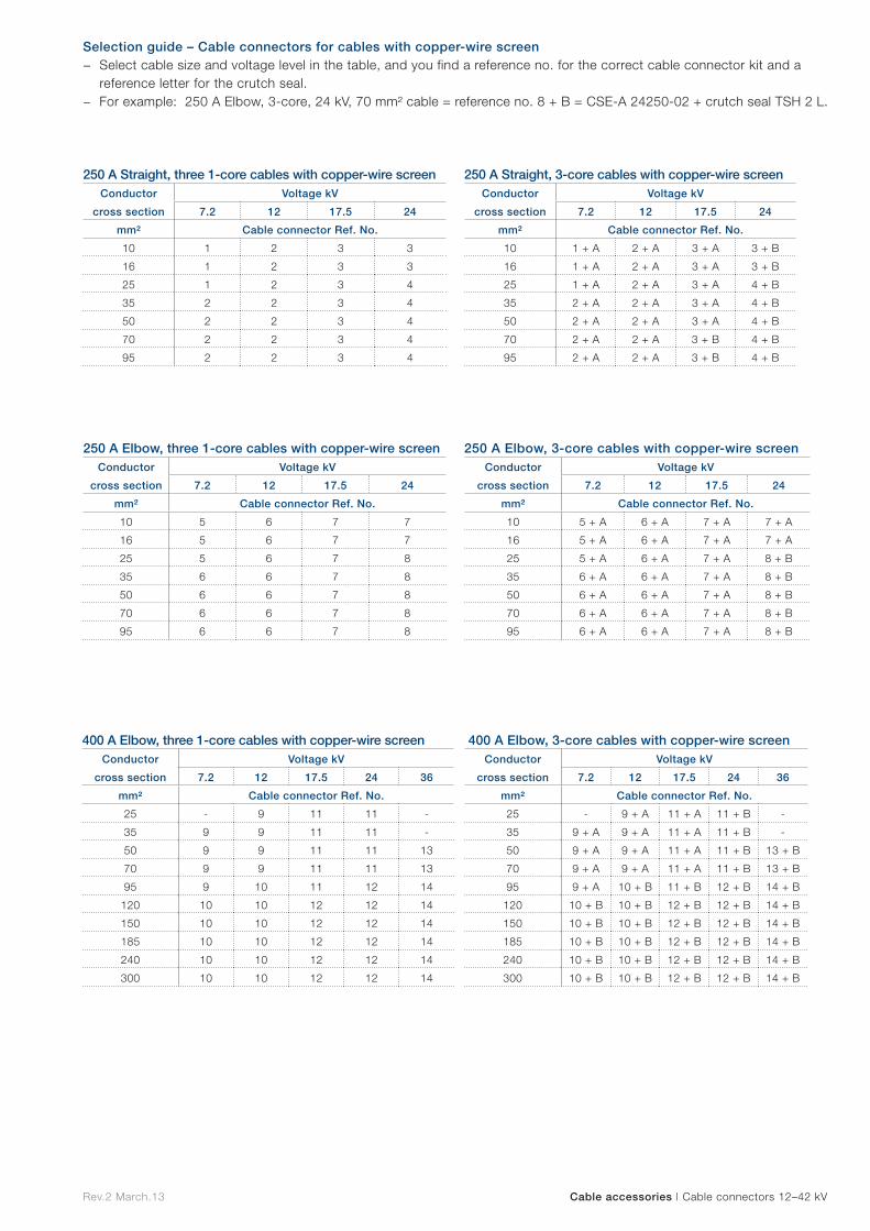
250 A Elbow, three 1-core cables with copper-wire screenConductor
cross section
Voltage kV
7.2 12 17.5 24
mm² Cable connector Ref. No.
10 5 6 7 7
16 5 6 7 7
25 5 6 7 8
35 6 6 7 8
50 6 6 7 8
70 6 6 7 8
95 6 6 7 8
250 A Elbow, 3-core cables with copper-wire screenConductor
cross section
Voltage kV
7.2 12 17.5 24
mm² Cable connector Ref. No.
10 5 + A 6 + A 7 + A 7 + A
16 5 + A 6 + A 7 + A 7 + A
25 5 + A 6 + A 7 + A 8 + B
35 6 + A 6 + A 7 + A 8 + B
50 6 + A 6 + A 7 + A 8 + B
70 6 + A 6 + A 7 + A 8 + B
95 6 + A 6 + A 7 + A 8 + B
400 A Elbow, three 1-core cables with copper-wire screenConductor
cross section
Voltage kV
7.2 12 17.5 24 36
mm² Cable connector Ref. No.
25 - 9 11 11 -
35 9 9 11 11 -
50 9 9 11 11 13
70 9 9 11 11 13
95 9 10 11 12 14
120 10 10 12 12 14
150 10 10 12 12 14
185 10 10 12 12 14
240 10 10 12 12 14
300 10 10 12 12 14
400 A Elbow, 3-core cables with copper-wire screenConductor
cross section
Voltage kV
7.2 12 17.5 24 36
mm² Cable connector Ref. No.
25 - 9 + A 11 + A 11 + B -
35 9 + A 9 + A 11 + A 11 + B -
50 9 + A 9 + A 11 + A 11 + B 13 + B
70 9 + A 9 + A 11 + A 11 + B 13 + B
95 9 + A 10 + B 11 + B 12 + B 14 + B
120 10 + B 10 + B 12 + B 12 + B 14 + B
150 10 + B 10 + B 12 + B 12 + B 14 + B
185 10 + B 10 + B 12 + B 12 + B 14 + B
240 10 + B 10 + B 12 + B 12 + B 14 + B
300 10 + B 10 + B 12 + B 12 + B 14 + B
Selection guide – Cable connectors for cables with copper-wire screen − Select cable size and voltage level in the table, and you find a reference no. for the correct cable connector kit and a
reference letter for the crutch seal. − For example: 250 A Elbow, 3-core, 24 kV, 70 mm² cable = reference no. 8 + B = CSE-A 24250-02 + crutch seal TSH 2 L.
250 A Straight, three 1-core cables with copper-wire screenConductor
cross section
Voltage kV
7.2 12 17.5 24
mm² Cable connector Ref. No.
10 1 2 3 3
16 1 2 3 3
25 1 2 3 4
35 2 2 3 4
50 2 2 3 4
70 2 2 3 4
95 2 2 3 4
250 A Straight, 3-core cables with copper-wire screenConductor
cross section
Voltage kV
7.2 12 17.5 24
mm² Cable connector Ref. No.
10 1 + A 2 + A 3 + A 3 + B
16 1 + A 2 + A 3 + A 3 + B
25 1 + A 2 + A 3 + A 4 + B
35 2 + A 2 + A 3 + A 4 + B
50 2 + A 2 + A 3 + A 4 + B
70 2 + A 2 + A 3 + B 4 + B
95 2 + A 2 + A 3 + B 4 + B
Cable accessories | Cable connectors 12–42 kV Rev.2 March.13
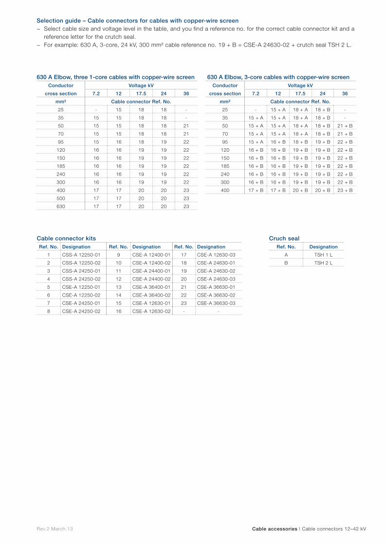
630 A Elbow, three 1-core cables with copper-wire screenConductor
cross section
Voltage kV
7.2 12 17.5 24 36
mm² Cable connector Ref. No.
25 - 15 18 18 -
35 15 15 18 18 -
50 15 15 18 18 21
70 15 15 18 18 21
95 15 16 18 19 22
120 16 16 19 19 22
150 16 16 19 19 22
185 16 16 19 19 22
240 16 16 19 19 22
300 16 16 19 19 22
400 17 17 20 20 23
500 17 17 20 20 23
630 17 17 20 20 23
630 A Elbow, 3-core cables with copper-wire screenConductor
cross section
Voltage kV
7.2 12 17.5 24 36
mm² Cable connector Ref. No.
25 - 15 + A 18 + A 18 + B -
35 15 + A 15 + A 18 + A 18 + B -
50 15 + A 15 + A 18 + A 18 + B 21 + B
70 15 + A 15 + A 18 + A 18 + B 21 + B
95 15 + A 16 + B 18 + B 19 + B 22 + B
120 16 + B 16 + B 19 + B 19 + B 22 + B
150 16 + B 16 + B 19 + B 19 + B 22 + B
185 16 + B 16 + B 19 + B 19 + B 22 + B
240 16 + B 16 + B 19 + B 19 + B 22 + B
300 16 + B 16 + B 19 + B 19 + B 22 + B
400 17 + B 17 + B 20 + B 20 + B 23 + B
Cable connector kitsRef. No. Designation Ref. No. Designation Ref. No. Designation
1 CSS-A 12250-01 9 CSE-A 12400-01 17 CSE-A 12630-03
2 CSS-A 12250-02 10 CSE-A 12400-02 18 CSE-A 24630-01
3 CSS-A 24250-01 11 CSE-A 24400-01 19 CSE-A 24630-02
4 CSS-A 24250-02 12 CSE-A 24400-02 20 CSE-A 24630-03
5 CSE-A 12250-01 13 CSE-A 36400-01 21 CSE-A 36630-01
6 CSE-A 12250-02 14 CSE-A 36400-02 22 CSE-A 36630-02
7 CSE-A 24250-01 15 CSE-A 12630-01 23 CSE-A 36630-03
8 CSE-A 24250-02 16 CSE-A 12630-02 - -
Cruch sealRef. No. Designation
A TSH 1 L
B TSH 2 L
Selection guide – Cable connectors for cables with copper-wire screen − Select cable size and voltage level in the table, and you find a reference no. for the correct cable connector kit and a
reference letter for the crutch seal. − For example: 630 A, 3-core, 24 kV, 300 mm² cable reference no. 19 + B = CSE-A 24630-02 + crutch seal TSH 2 L.
Cable accessories | Cable connectors 12–42 kV Rev.2 March.13
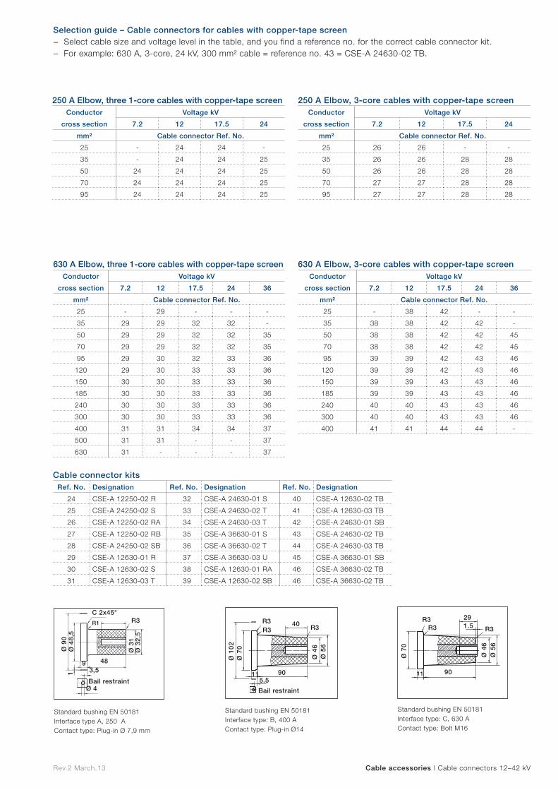
Standard bushing EN 50181 Interface type: C, 630 A Contact type: Bolt M16
Ø 4
6Ø
56
R3R3
Ø 7
0
11 90
R3 1.529
Standard bushing EN 50181 Interface type A, 250 A Contact type: Plug-in Ø 7,9 mm
Standard bushing EN 50181 Interface type: B, 400 A Contact type: Plug-in Ø14
R3
Ø 4
6
Ø 7
0Ø
102
115.5
Bail restraint
40R3R3
Ø 5
6
90
250 A Elbow, three 1-core cables with copper-tape screenConductor
cross section
Voltage kV
7.2 12 17.5 24
mm² Cable connector Ref. No.
25 - 24 24 -
35 - 24 24 25
50 24 24 24 25
70 24 24 24 25
95 24 24 24 25
250 A Elbow, 3-core cables with copper-tape screenConductor
cross section
Voltage kV
7.2 12 17.5 24
mm² Cable connector Ref. No.
25 26 26 - -
35 26 26 28 28
50 26 26 28 28
70 27 27 28 28
95 27 27 28 28
630 A Elbow, three 1-core cables with copper-tape screenConductor
cross section
Voltage kV
7.2 12 17.5 24 36
mm² Cable connector Ref. No.
25 - 29 - - -
35 29 29 32 32 -
50 29 29 32 32 35
70 29 29 32 32 35
95 29 30 32 33 36
120 29 30 33 33 36
150 30 30 33 33 36
185 30 30 33 33 36
240 30 30 33 33 36
300 30 30 33 33 36
400 31 31 34 34 37
500 31 31 - - 37
630 31 - - - 37
630 A Elbow, 3-core cables with copper-tape screenConductor
cross section
Voltage kV
7.2 12 17.5 24 36
mm² Cable connector Ref. No.
25 - 38 42 - -
35 38 38 42 42 -
50 38 38 42 42 45
70 38 38 42 42 45
95 39 39 42 43 46
120 39 39 42 43 46
150 39 39 43 43 46
185 39 39 43 43 46
240 40 40 43 43 46
300 40 40 43 43 46
400 41 41 44 44 -
Cable connector kitsRef. No. Designation Ref. No. Designation Ref. No. Designation
24 CSE-A 12250-02 R 32 CSE-A 24630-01 S 40 CSE-A 12630-02 TB
25 CSE-A 24250-02 S 33 CSE-A 24630-02 T 41 CSE-A 12630-03 TB
26 CSE-A 12250-02 RA 34 CSE-A 24630-03 T 42 CSE-A 24630-01 SB
27 CSE-A 12250-02 RB 35 CSE-A 36630-01 S 43 CSE-A 24630-02 TB
28 CSE-A 24250-02 SB 36 CSE-A 36630-02 T 44 CSE-A 24630-03 TB
29 CSE-A 12630-01 R 37 CSE-A 36630-03 U 45 CSE-A 36630-01 SB
30 CSE-A 12630-02 S 38 CSE-A 12630-01 RA 46 CSE-A 36630-02 TB
31 CSE-A 12630-03 T 39 CSE-A 12630-02 SB 46 CSE-A 36630-02 TB
Selection guide – Cable connectors for cables with copper-tape screen − Select cable size and voltage level in the table, and you find a reference no. for the correct cable connector kit. − For example: 630 A, 3-core, 24 kV, 300 mm² cable = reference no. 43 = CSE-A 24630-02 TB.
R3R1
C 2x45°
Bail restraintØ 4
3,5
Ø 4
8,5
Ø 9
0
Ø 3
1
1
Ø 3
2,5
9 48
Cable accessories | Cable connectors 12–42 kV Rev.2 March.13
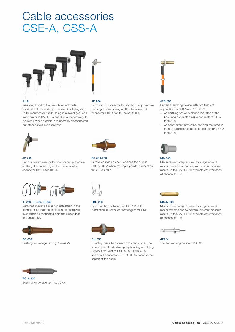
PG 630Bushing for voltage testing, 12–24 kV.
CU 250 Coupling piece to connect two connectors. The kit consists of a double epoxy bushing with fixing lugs bail restraint to CSE-A 250, CSS-A 250 and a bolt connector SH-SKR 35 to connect the screen of the cable.
LBR 250 Extended bail restraint for CSS-A 250 for installation in Schneider switchgear MGRM6.
JP 250 Earth circuit connector for short-circuit protective earthing. For mounting on the disconnected connector CSE-A for 12–24 kV, 250 A.
JPA V Tool for earthing device, JPB 630.
JP 400 Earth circuit connector for short-circuit protective earthing. For mounting on the disconnected connector CSE-A for 400 A.
MA 250 Measurement adapter used for mega ohm Ω measurements and to perform different measure-ments up to 5 kV DC, for example determination of phases, 250 A.
MA-A 630 Measurement adapter used for mega ohm Ω measurements and to perform different measure-ments up to 5 kV DC, for example determination of phases, 630 A.
PC 630/250 Parallel coupling piece. Replaces the plug in CSE-A 630 A when making a parallel connection to CSE-A 250 A.
Cable accessories CSE-A, CSS-A
IP 250, IP 400, IP 630 Screened insulating plug for installation in the connector so that the cable can be energized even when disconnected from the switchgear or transformer.
PG-A 630 Bushing for voltage testing, 36 kV.
JPB 630 Universal earthing device with two fields of application for 630 A and 12–36 kV:
− As earthing-for-work device mounted at the back of a connected cable connector CSE-A for 630 A.
− As short-circuit protective earthing mounted in front of a disconnected cable connector CSE-A for 630 A.
IH-A Insulating hood of flexible rubber with outer conductive layer and a preinstalled insulating rod. To be mounted on the bushing in a switchgear or a transformer 250A, 400 A and 630 A respectively, to insulate it when a cable is temporarily disconnected but other cables are energized.
Cable accessories | CSE-A, CSS-ARev.2 March.13

Designation Description Quantity Weight
kg/kit
IH-A 24250 Insulating hood, 250 A 3 per kit 2.3
IH-A 24400 Insulating hood, 400 A 3 per kit 5.2
IH-A 24630 Insulating hood, 630 A 3 per kit 5.2
IH-A 42400 Insulating hood, for 400 A 3 5.5
IH-A 42630 Insulating hood, for 630 A 3 5.5
JP 250 Earth circuit connector, 250 A 3 per kit in a case 2.7
JP 400 Earth circuit connector, 400 A 1 per kit 5.5
JPB 630 Earth circuit connector, 630 A 1 per kit 5.0
IP 250 Screened insulating plug, 250 A 1 per kit 0.8
IP 400 Screened insulating plug, 400 A 1 per kit 2.2
IP 630 Screened insulating plug, 630 A 1 per kit 2.2
PG 630 Bushing for voltage testing, 630 A, 12–24 kV 1 per kit 1.5
PG-A 630 Bushing for voltage testing, 630 A, 36-42 kV 1 per kit 2.0
PC 630/250 Parallel coupling piece 3 per kit + hex bit socket 3.0
LBR 250 Extended bail restraint 3 per kit 0.01
CU 250 Parallel coupling piece between two cable connectors, 250 A 1 per kit 0.2
MA 250 Measurement adapter, 250 A 1 per kit 0.3
MA-A 630 Measurement adapter, 630 A 3 per kit 0.2
JPA V Tool for earthing device, JPB 630 1 per kit 1.8
Cable accessories | Selection table
Cable accessories Selection table
Rev.2 March.13
CSE-A screened separable cable connector installed with CSEP-A parallel connector. This combination fulfills the requirements of CENELEC HD 629.1 S2.
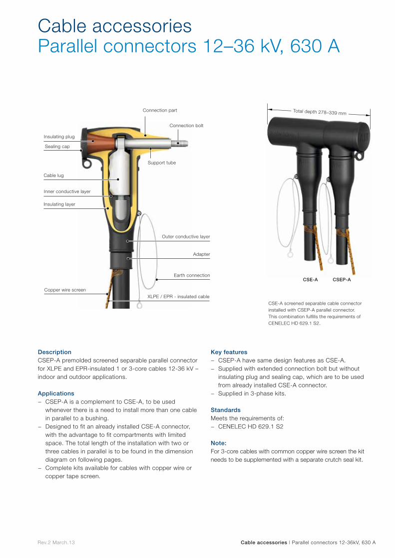
Cable accessories Parallel connectors 12–36 kV, 630 A
Connection part
Connection bolt
Insulating plug
Support tube
Cable lug
Inner conductive layer
Insulating layer
Outer conductive layer
Adapter
Earth connection
XLPE / EPR - insulated cableCopper wire screen
Sealing cap
CSE-A CSEP-A
Total depth 278–339 mm
DescriptionCSEP-A premolded screened separable parallel connector for XLPE and EPR-insulated 1 or 3-core cables 12-36 kV – indoor and outdoor applications. Applications
− CSEP-A is a complement to CSE-A, to be used whenever there is a need to install more than one cable in parallel to a bushing.
− Designed to fit an already installed CSE-A connector, with the advantage to fit compartments with limited space. The total length of the installation with two or three cables in parallel is to be found in the dimension diagram on following pages.
− Complete kits available for cables with copper wire or copper tape screen.
Key features − CSEP-A have same design features as CSE-A. − Supplied with extended connection bolt but without
insulating plug and sealing cap, which are to be used from already installed CSE-A connector.
− Supplied in 3-phase kits.
StandardsMeets the requirements of:
− CENELEC HD 629.1 S2 Note:For 3-core cables with common copper wire screen the kit needs to be supplemented with a separate crutch seal kit.
Cable accessories | Parallel connectors 12-36kV, 630 ARev.2 March.13
630 A Parallel, three 1-core cables with copper-wire screenConductor
cross section
Voltage kV
7.2 12 17.5 24 36
mm² Parallel connector Ref. No.
25 - 47 50 50 -
35 47 47 50 50 -
50 47 47 50 50 53
70 47 47 50 50 53
95 47 48 50 50 54
120 48 48 51 51 54
150 48 48 51 51 54
185 48 48 51 51 54
240 48 48 51 51 54
300 48 48 51 51 54
400 49 49 52 52 55
500 49 49 52 52 55
630 49 49 52 52 55
630 A Parallel, 3-core cables with copper-wire screenConductor
cross section
Voltage kV
7.2 12 17.5 24 36
mm² Parallel connector Ref. No.
25 - 47 + A 50 + A 50 + A -
35 47 + A 47 + A 50 + A 50 + A -
50 47 + A 47 + A 50 + A 50 + A 53 + B
70 47 + A 47 + A 50 + A 50 + A 53 + B
95 47 + A 48 + B 50 + A 51 + B 54 + B
120 48 + B 48 + B 51 + B 51 + B 54 + B
150 48 + B 48 + B 51 + B 51 + B 54 + B
185 48 + B 48 + B 51 + B 51 + B 54 + B
240 48 + B 48 + B 51 + B 51 + B 54 + B
300 48 + B 48 + B 51 + B 51 + B 54 + B
400 49 + B 49 + B 52 + B 52 + B 55 + B
Crutch sealRef. No. Designation
A TSH 1 L
B TSH 2 L
630 A Parallel, three 1-core cables with copper-tape screenConductor
cross section
Voltage kV
7.2 12 17.5 24 36
mm² Parallel connector Ref. No.
25 - 56 - - -
35 56 56 59 59 -
50 56 56 59 59 62
70 56 56 59 59 62
95 56 57 59 60 63
120 56 57 60 60 63
150 57 57 60 60 63
185 57 57 60 60 63
240 57 57 60 60 63
300 57 57 60 60 63
400 58 58 61 61 64
500 58 58 - - 64
630 58 - - - 64
630 A Parallel, 3-core cables with copper-tape screenConductor
cross section
Voltage kV
7.2 12 17.5 24 36
mm² Parallel connector Ref. No.
25 - 65 69 - -
35 65 65 69 69 -
50 65 65 69 69 72
70 65 65 69 69 72
95 66 66 69 70 73
120 66 66 69 70 73
150 66 66 70 70 73
185 66 66 70 70 73
240 67 67 70 70 73
300 67 67 70 70 73
400 68 68 71 71 -
Parallel connector kitRef. No. Designation Ref. No. Designation Ref. No. Designation
47 CSEP-A 12630-01 56 CSEP-A 12630-01 R 65 CSEP-A 12630-01 RA
48 CSEP-A 12630-02 57 CSEP-A 12630-02 S 66 CSEP-A 12630-02 SB
49 CSEP-A 12630-03 58 CSEP-A 12630-03 T 67 CSEP-A 12630-02 TB
50 CSEP-A 24630-01 59 CSEP-A 24630-01 S 68 CSEP-A 12630-03 TB
51 CSEP-A 24630-02 60 CSEP-A 24630-02 T 69 CSEP-A 24630-01 SB
52 CSEP-A 24630-03 61 CSEP-A 24630-03 T 70 CSEP-A 24630-02 TB
53 CSEP-A 36630-01 62 CSEP-A 36630-01 S 71 CSEP-A 24630-03 TB
54 CSEP-A 36630-02 63 CSEP-A 36630-02 T 72 CSEP-A 36630-01 SB
55 CSEP-A 36630-03 64 CSEP-A 36630-03 U 73 CSEP-A 36630-02 TB
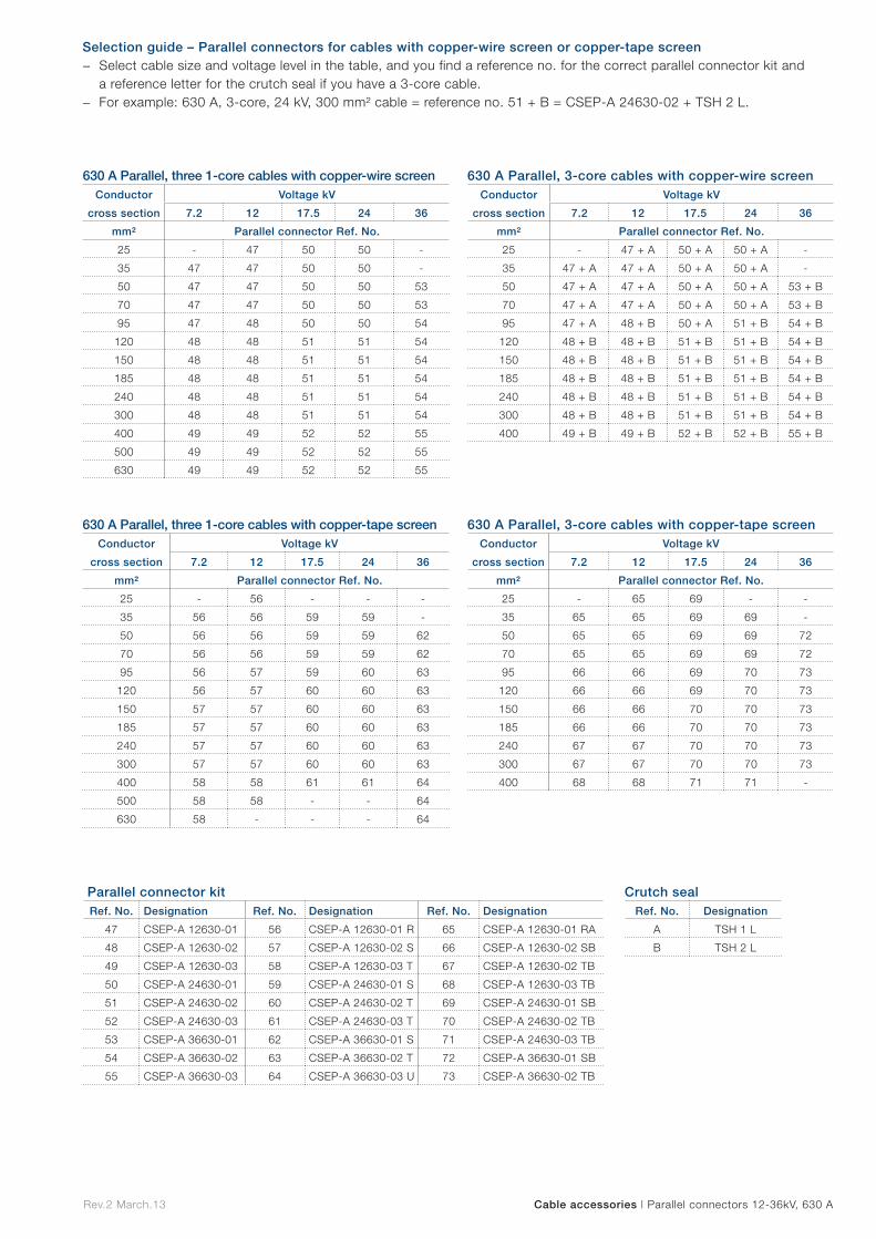
Selection guide – Parallel connectors for cables with copper-wire screen or copper-tape screen − Select cable size and voltage level in the table, and you find a reference no. for the correct parallel connector kit and
a reference letter for the crutch seal if you have a 3-core cable. − For example: 630 A, 3-core, 24 kV, 300 mm² cable = reference no. 51 + B = CSEP-A 24630-02 + TSH 2 L.
Cable accessories | Parallel connectors 12-36kV, 630 ARev.2 March.13
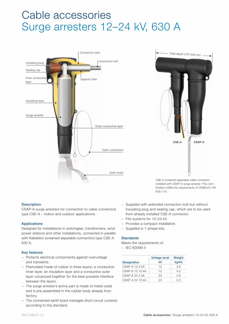
CSE-A screened separable cable connector installed with CSAP-A surge arrester. This com-bination fulfills the requirements of CENELEC HD 629.1 S1.
Cable accessoriesSurge arresters 12–24 kV, 630 A
Designation
Voltage level Weight
kV kg/kit
CSAP-A 12 5 kA 12 3.6
CSAP-A 12 10 kA 12 4.0
CSAP-A 24 5 kA 24 4.6
CSAP-A 24 10 kA 24 5.0
Connection part
Connection boltInsulating plug
Support tube
Surge arrester
Outer conductive layer
Inner conductive layer
Earth connection
Earth braid
Insulating layer
Sealing cap
CSE-A CSAP-A
Total depth 278–339 mm
DescriptionCSAP-A surge arresters for connection to cable connectors type CSE-A – indoor and outdoor applications. ApplicationsDesigned for installations in switchgear, transformers, wind power stations and other installations, connected in parallel with Kabeldon screened separable connectors type CSE-A 630 A.
Key features − Protects electrical components against overvoltage
and transients. − Premolded made of rubber in three layers; a conductive
inner layer, an insulation layer and a conductive outer layer vulcanized together for the best possible interface between the layers.
− The surge arrester’s active part is made of metal oxide and is pre-assembled in the rubber body already from factory.
− The connected earth braid manages short circuit currents according to the standard.
− Supplied with extended connection bolt but without insulating plug and sealing cap, which are to be used from already installed CSE-A connector.
− Fits systems for 12–24 kV. − Provides a compact installation. − Supplied in 1-phase kits.
StandardsMeets the requirements of:
− IEC 60099-4
Cable accessories | Surge arresters 12–24 kV, 630 A Rev.2 March.13
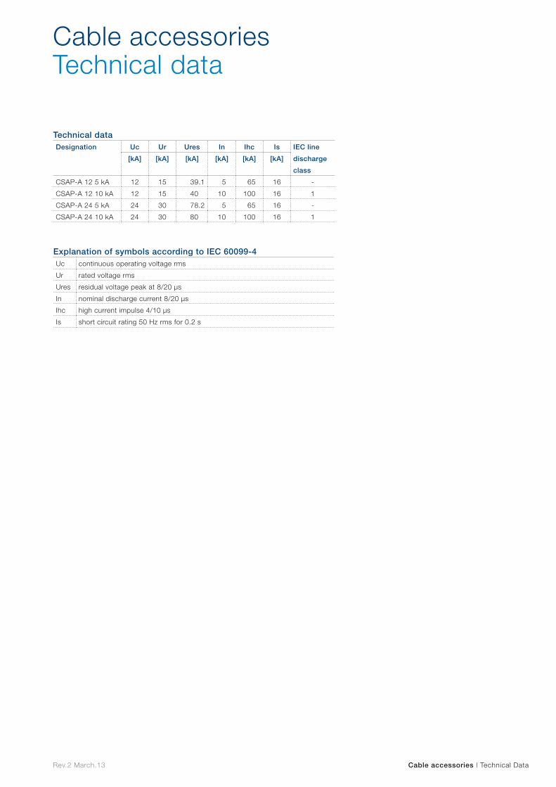
Technical dataDesignation Uc Ur Ures In Ihc Is IEC line
discharge
class
[kA] [kA] [kA] [kA] [kA] [kA]
CSAP-A 12 5 kA 12 15 39.1 5 65 16 -
CSAP-A 12 10 kA 12 15 40 10 100 16 1
CSAP-A 24 5 kA 24 30 78.2 5 65 16 -
CSAP-A 24 10 kA 24 30 80 10 100 16 1
Explanation of symbols according to IEC 60099-4Uc continuous operating voltage rms
Ur rated voltage rms
Ures residual voltage peak at 8/20 µs
In nominal discharge current 8/20 µs
Ihc high current impulse 4/10 µs
Is short circuit rating 50 Hz rms for 0.2 s
Cable accessories | Technical Data
Cable accessoriesTechnical data
Rev.2 March.13

Capacitors and filters
Cap
acitors
and filters

Rev.2 Feb.13
ABB offers a wide range of capacitors, filter components and solutions for LV, MV and HV applications.
These components and solutions enable customers to comply with power factor and harmonic limitation targets imposed by utilities, ensuring that your installations operate with maximum efficiency.
Capacitors and filters
Capacitors and filters
The ABB portfolio consists of various components (e.g. capacitor units, capacitor switches, power factor controllers), that can be assembled into capacitor compensation panels and banks by panel builders and other OEMs.
The portfolio also contains solutions (e.g. capacitor banks with and without reactors and active filters) that can be readily and easily installed.
Servicing of the equipment becomes easy with a portable capacitance meter and integrated help menus in the ABB capacitor bank and filter controllers.
Reactive power compensation banks
Harmonic filtering Capacitor units

LV applications
LV
app
lications
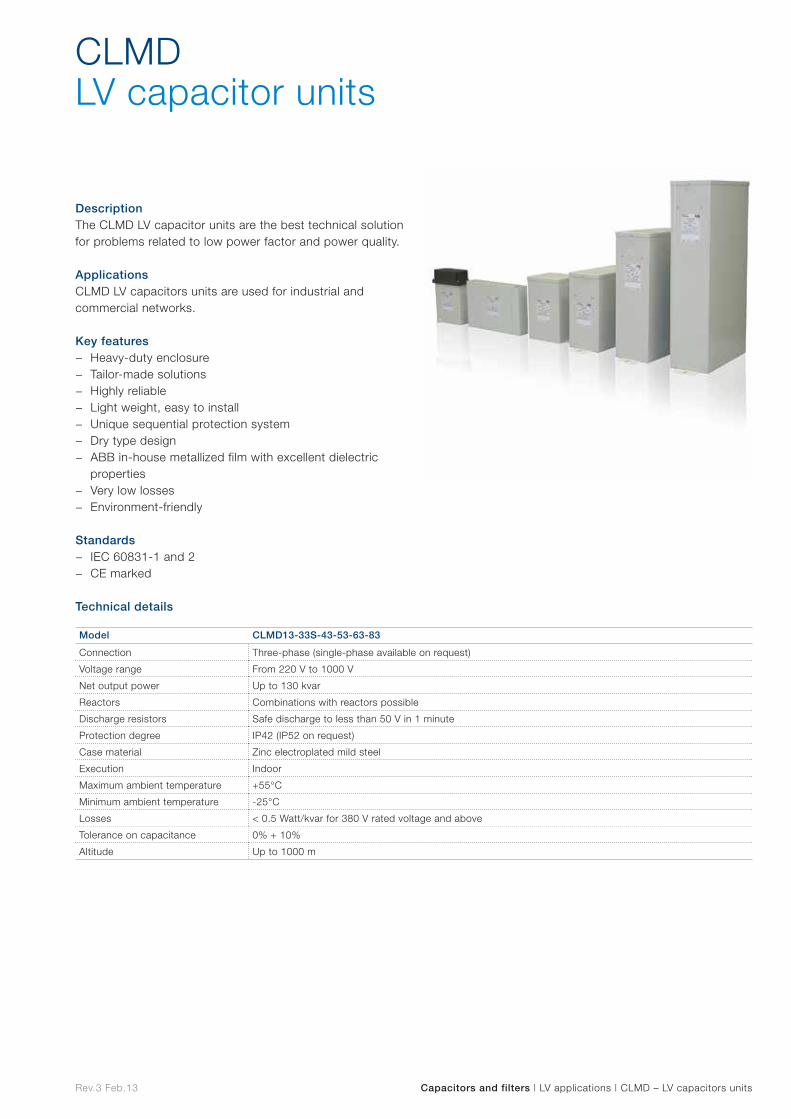
Rev.3 Feb.13 Capacitors and filters | LV applications | CLMD – LV capacitors units
DescriptionThe CLMD LV capacitor units are the best technical solution for problems related to low power factor and power quality.
ApplicationsCLMD LV capacitors units are used for industrial and commercial networks.
Key features − Heavy-duty enclosure − Tailor-made solutions − Highly reliable − Light weight, easy to install − Unique sequential protection system − Dry type design − ABB in-house metallized film with excellent dielectric
properties − Very low losses − Environment-friendly
Standards − IEC 60831-1 and 2 − CE marked
Technical details
CLMDLV capacitor units
Model CLMD13-33S-43-53-63-83
Connection Three-phase (single-phase available on request)
Voltage range From 220 V to 1000 V
Net output power Up to 130 kvar
Reactors Combinations with reactors possible
Discharge resistors Safe discharge to less than 50 V in 1 minute
Protection degree IP42 (IP52 on request)
Case material Zinc electroplated mild steel
Execution Indoor
Maximum ambient temperature +55°C
Minimum ambient temperature -25°C
Losses < 0.5 Watt/kvar for 380 V rated voltage and above
Tolerance on capacitance 0% + 10%
Altitude Up to 1000 m
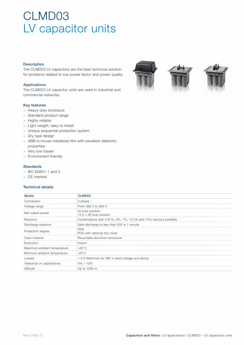
Rev.3 Feb.13 Capacitors and filters | LV applications | CLMD03 – LV capacitors units
DescriptionThe CLMD03 LV capacitors are the best technical solution for problems related to low power factor and power quality.
ApplicationsThe CLMD03 LV capacitor units are used in industrial and commercial networks.
Key features − Heavy-duty enclosure − Standard product range − Highly reliable − Light weight, easy to install − Unique sequential protection system − Dry type design − ABB in-house metallized film with excellent dielectric
properties − Very low losses − Environment-friendly
Standards − IEC 60831-1 and 2 − CE marked
Technical details
CLMD03LV capacitor units
Model CLMD03
Connection 3-phase
Voltage range From 380 V to 690 V
Net output power50 kvar solution12.5 + 25 kvar solution
Reactors Combinations with 5.67%, 6%, 7%, 12.5% and 14% reactors possible
Discharge resistors Safe discharge to less than 50V in 1 minute
Protection degreeIP00IP20 with optional top cover
Case material Recyclable aluminum enclosure
Execution Indoor
Maximum ambient temperature +55°C
Minimum ambient temperature -25°C
Losses < 0.5 Watt/kvar for 380 V rated voltage and above
Tolerance on capacitance 0% + 10%
Altitude Up to 1000 m
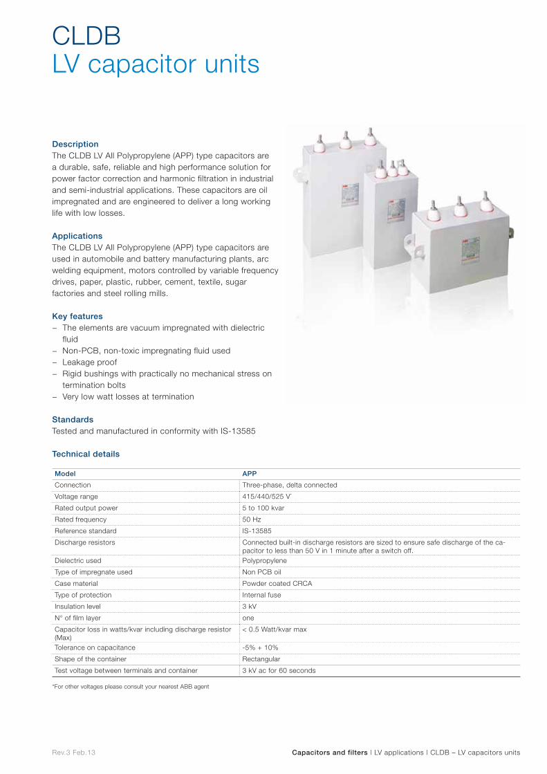
Rev.3 Feb.13 Capacitors and filters | LV applications | CLDB – LV capacitors units
DescriptionThe CLDB LV All Polypropylene (APP) type capacitors are a durable, safe, reliable and high performance solution for power factor correction and harmonic filtration in industrial and semi-industrial applications. These capacitors are oil impregnated and are engineered to deliver a long working life with low losses.
ApplicationsThe CLDB LV All Polypropylene (APP) type capacitors are used in automobile and battery manufacturing plants, arc welding equipment, motors controlled by variable frequency drives, paper, plastic, rubber, cement, textile, sugar factories and steel rolling mills.
Key features − The elements are vacuum impregnated with dielectric
fluid − Non-PCB, non-toxic impregnating fluid used − Leakage proof − Rigid bushings with practically no mechanical stress on
termination bolts − Very low watt losses at termination
StandardsTested and manufactured in conformity with IS-13585
Technical details
CLDBLV capacitor units
Model APP
Connection Three-phase, delta connected
Voltage range 415/440/525 V*
Rated output power 5 to 100 kvar
Rated frequency 50 Hz
Reference standard IS-13585
Discharge resistors Connected built-in discharge resistors are sized to ensure safe discharge of the ca-pacitor to less than 50 V in 1 minute after a switch off.
Dielectric used Polypropylene
Type of impregnate used Non PCB oil
Case material Powder coated CRCA
Type of protection Internal fuse
Insulation level 3 kV
N° of film layer one
Capacitor loss in watts/kvar including discharge resistor (Max)
< 0.5 Watt/kvar max
Tolerance on capacitance -5% + 10%
Shape of the container Rectangular
Test voltage between terminals and container 3 kV ac for 60 seconds
*For other voltages please consult your nearest ABB agent
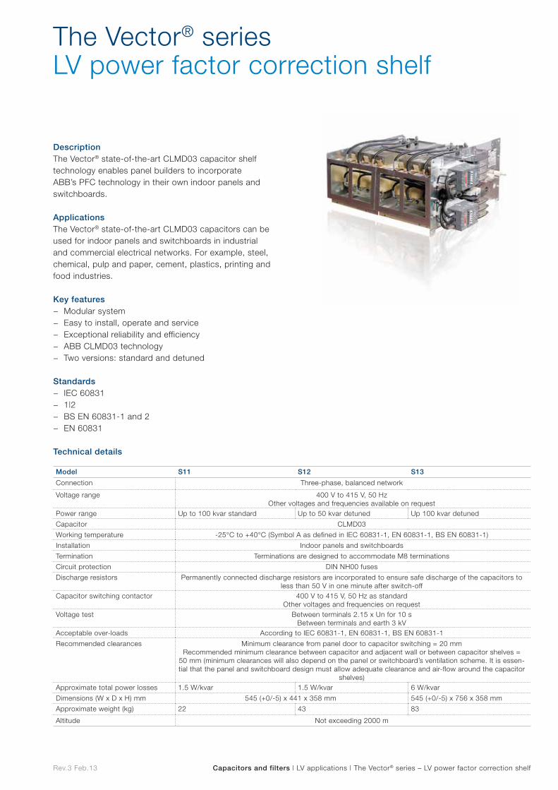
Rev.3 Feb.13 Capacitors and filters | LV applications | The Vector® series – LV power factor correction shelf
DescriptionThe Vector® state-of-the-art CLMD03 capacitor shelf technology enables panel builders to incorporate ABB’s PFC technology in their own indoor panels and switchboards.
ApplicationsThe Vector® state-of-the-art CLMD03 capacitors can be used for indoor panels and switchboards in industrial and commercial electrical networks. For example, steel, chemical, pulp and paper, cement, plastics, printing and food industries.
Key features − Modular system − Easy to install, operate and service − Exceptional reliability and efficiency − ABB CLMD03 technology − Two versions: standard and detuned
Standards − IEC 60831 − 1|2 − BS EN 60831-1 and 2 − EN 60831
Technical details
The Vector® seriesLV power factor correction shelf
Model S11 S12 S13
Connection Three-phase, balanced network
Voltage range 400 V to 415 V, 50 HzOther voltages and frequencies available on request
Power range Up to 100 kvar standard Up to 50 kvar detuned Up 100 kvar detuned
Capacitor CLMD03
Working temperature -25°C to +40°C (Symbol A as defined in IEC 60831-1, EN 60831-1, BS EN 60831-1)
Installation Indoor panels and switchboards
Termination Terminations are designed to accommodate M8 terminations
Circuit protection DIN NH00 fuses
Discharge resistors Permanently connected discharge resistors are incorporated to ensure safe discharge of the capacitors to less than 50 V in one minute after switch-off
Capacitor switching contactor 400 V to 415 V, 50 Hz as standard Other voltages and frequencies on request
Voltage test Between terminals 2.15 x Un for 10 sBetween terminals and earth 3 kV
Acceptable over-loads According to IEC 60831-1, EN 60831-1, BS EN 60831-1
Recommended clearances Minimum clearance from panel door to capacitor switching = 20 mmRecommended minimum clearance between capacitor and adjacent wall or between capacitor shelves =
50 mm (minimum clearances will also depend on the panel or switchboard’s ventilation scheme. It is essen-tial that the panel and switchboard design must allow adequate clearance and air-flow around the capacitor
shelves)Approximate total power losses 1.5 W/kvar 1.5 W/kvar 6 W/kvar
Dimensions (W x D x H) mm 545 (+0/-5) x 441 x 358 mm 545 (+0/-5) x 756 x 358 mm
Approximate weight (kg) 22 43 83
Altitude Not exceeding 2000 m

Rev.3 Feb.13 Capacitors and filters | LV applications | APC – LV contactor-switched capacitor banks
DescriptionThe APC LV contactor-switched capacitor banks provide the ideal automatic power factor correction solution.
ApplicationsThe APC LV contactor-switched capacitor bank can be used in industrial and commercial networks. For example mining, steel, chemical, pulp and paper, cement, plastics, printing and food industries.
Key features − Powerful and compact − Easy to install and use with the RVC controller − Exceptional reliability and safety − ABB CLMD technology − Detuning reactors − Two versions: wall-mounted and free-standing floor
mounted cubicles
Standards − EN61921 − IEC60831-1 and 2 − CE
Technical details
APCLV contactor-switched capacitor banks
Model APCL03 APCM03 APCR03
Connection Three-phase, balanced network
Voltage range400 V and 415 V at 50 Hz380 V and 480 V at 60 Hz
Power range From 50 to 600 kvar in one enclosure
Reactors –
Dry type resin embedded according to IEC289, IEC76Maximum harmonic pollution: 8% THDV with specific spectrum
Working ambient temperature -5°C/+40°C according to EN61921
InstallationWall mounting, bottom cable entry
Free floor standing, bottom cable entry (top entry optional)
Protection degree IP21 (closed door) IP23 (closed door)
Execution Indoor
Ventilation Air forced cooling
Capacitors CLMD type
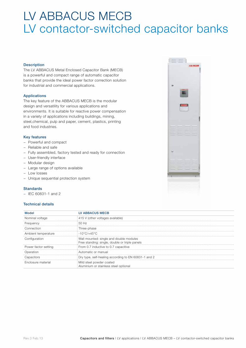
Rev.3 Feb.13 Capacitors and filters | LV applications | LV ABBACUS MECB – LV contactor-switched capacitor banks
DescriptionThe LV ABBACUS Metal Enclosed Capacitor Bank (MECB) is a powerful and compact range of automatic capacitor banks that provide the ideal power factor correction solution for industrial and commercial applications.
ApplicationsThe key feature of the ABBACUS MECB is the modular design and versatility for various applications and environments. It is suitable for reactive power compensation in a variety of applications including buildings, mining, steel,chemical, pulp and paper, cement, plastics, printing and food industries. Key features
− Powerful and compact − Reliable and safe − Fully assembled, factory tested and ready for connection − User-friendly interface − Modular design − Large range of options available − Low losses − Unique sequential protection system
Standards − IEC 60831-1 and 2
Technical details
LV ABBACUS MECBLV contactor-switched capacitor banks
Model LV ABBACUS MECB
Nominal voltage 415 V (other voltages available)
Frequency 50 Hz
Connection Three-phase
Ambient temperature -10°C/+45°C
Configuration Wall mounted: single and double modulesFree standing: single, double or triple panels
Power factor setting From 0.7 inductive to 0.7 capacitive
Operation Automatic or manual
Capacitors Dry type, self-healing according to EN 60831-1 and 2
Enclosure material Mild steel powder coatedAluminium or stainless steel optional
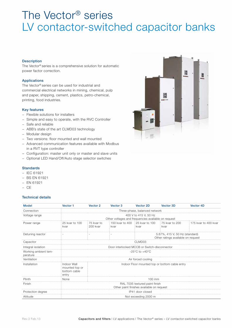
Rev.3 Feb.13 Capacitors and filters | LV applications | The Vector® series – LV contactor-switched capacitor banks
DescriptionThe Vector® series is a comprehensive solution for automatic power factor correction.
ApplicationsThe Vector® series can be used for industrial and commercial electrical networks in mining, chemical, pulp and paper, shipping, cement, plastics, petro-chemical, printing, food industries.
Key features − Flexible solutions for installers − Simple and easy to operate, with the RVC Controller − Safe and reliable − ABB’s state of the art CLMD03 technology − Modular design − Two versions: floor mounted and wall mounted − Advanced communication features available with Modbus
in a RVT type controller − Configuration: master unit only or master and slave units − Optional LED Hand/Off/Auto stage selector switches
Standards − IEC 61921 − BS EN 61921 − EN 61921 − CE
Technical details
The Vector® seriesLV contactor-switched capacitor banks
Model Vector 1 Vector 2 Vector 3 Vector 2D Vector 3D Vector 4D
Connection Three-phase, balanced network
Voltage range 400 V to 415 V, 50 HzOther voltages and frequencies available on request
Power range 25 kvar to 100 kvar
75 kvar to 200 kvar
150 kvar to 400 kvar
25 kvar to 100 kvar
75 kvar to 200 kvar
175 kvar to 400 kvar
Detuning reactor - - - 5.67%, 415 V, 50 Hz (standard)Other ratings available on request
Capacitor CLMD03
Integral isolation Door interlocked MCCB or Switch-disconnector
Working ambient tem-perature
-25°C to +40°C
Ventilation Air forced cooling
Installation Indoor Wall mounted top or bottom cable entry
Indoor Floor mounted top or bottom cable entry
Plinth None 100 mm
Finish RAL 7035 textured paint finishOther paint finishes available on request
Protection degree IP41 door closed
Altitude Not exceeding 2000 m
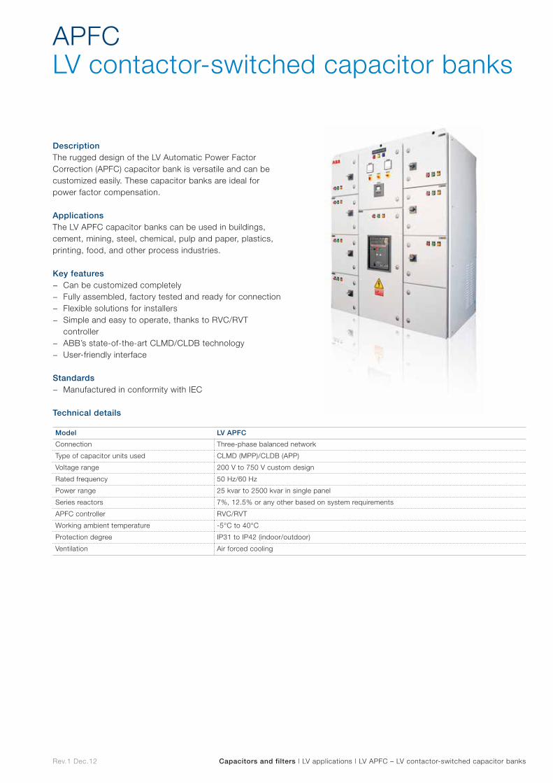
Rev.1 Dec.12 Capacitors and filters | LV applications | LV APFC – LV contactor-switched capacitor banks
DescriptionThe rugged design of the LV Automatic Power Factor Correction (APFC) capacitor bank is versatile and can be customized easily. These capacitor banks are ideal for power factor compensation.
ApplicationsThe LV APFC capacitor banks can be used in buildings, cement, mining, steel, chemical, pulp and paper, plastics, printing, food, and other process industries.
Key features − Can be customized completely − Fully assembled, factory tested and ready for connection − Flexible solutions for installers − Simple and easy to operate, thanks to RVC/RVT
controller − ABB’s state-of-the-art CLMD/CLDB technology − User-friendly interface
Standards − Manufactured in conformity with IEC
Technical details
APFCLV contactor-switched capacitor banks
Model LV APFC
Connection Three-phase balanced network
Type of capacitor units used CLMD (MPP)/CLDB (APP)
Voltage range 200 V to 750 V custom design
Rated frequency 50 Hz/60 Hz
Power range 25 kvar to 2500 kvar in single panel
Series reactors 7%, 12.5% or any other based on system requirements
APFC controller RVC/RVT
Working ambient temperature -5°C to 40°C
Protection degree IP31 to IP42 (indoor/outdoor)
Ventilation Air forced cooling
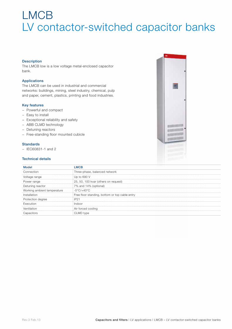
Rev.3 Feb.13 Capacitors and filters | LV applications | LMCB – LV contactor-switched capacitor banks
DescriptionThe LMCB low is a low voltage metal-enclosed capacitor bank.
ApplicationsThe LMCB can be used in industrial and commercial networks: buildings, mining, steel industry, chemical, pulp and paper, cement, plastics, printing and food industries.
Key features − Powerful and compact − Easy to install − Exceptional reliability and safety − ABB CLMD technology − Detuning reactors − Free-standing floor mounted cubicle
Standards − IEC60831-1 and 2
Technical details
LMCBLV contactor-switched capacitor banks
Model LMCB
Connection Three-phase, balanced network
Voltage range Up to 690 V
Power range 25, 50, 100 kvar (others on request)
Detuning reactor 7% and 14% (optional)
Working ambient temperature -5°C/+40°C
Installation Free floor standing, bottom or top cable entry
Protection degree IP21
Execution Indoor
Ventilation Air forced cooling
Capacitors CLMD type
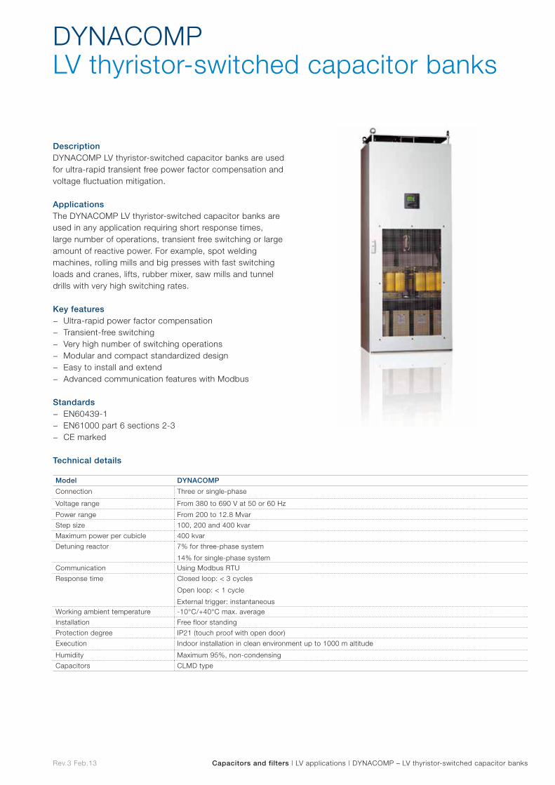
Rev.3 Feb.13 Capacitors and filters | LV applications | DYNACOMP – LV thyristor-switched capacitor banks
DescriptionDYNACOMP LV thyristor-switched capacitor banks are used for ultra-rapid transient free power factor compensation and voltage fluctuation mitigation.
ApplicationsThe DYNACOMP LV thyristor-switched capacitor banks areused in any application requiring short response times, large number of operations, transient free switching or large amount of reactive power. For example, spot welding machines, rolling mills and big presses with fast switching loads and cranes, lifts, rubber mixer, saw mills and tunnel drills with very high switching rates. Key features
− Ultra-rapid power factor compensation − Transient-free switching − Very high number of switching operations − Modular and compact standardized design − Easy to install and extend − Advanced communication features with Modbus
Standards − EN60439-1 − EN61000 part 6 sections 2-3 − CE marked
Technical details
DYNACOMPLV thyristor-switched capacitor banks
Model DYNACOMP
Connection Three or single-phase
Voltage range From 380 to 690 V at 50 or 60 Hz
Power range From 200 to 12.8 Mvar
Step size 100, 200 and 400 kvar
Maximum power per cubicle 400 kvar
Detuning reactor 7% for three-phase system
14% for single-phase systemCommunication Using Modbus RTU
Response time Closed loop: < 3 cycles
Open loop: < 1 cycle
External trigger: instantaneousWorking ambient temperature -10°C/+40°C max. average
Installation Free floor standing
Protection degree IP21 (touch proof with open door)
Execution Indoor installation in clean environment up to 1000 m altitude
Humidity Maximum 95%, non-condensing
Capacitors CLMD type
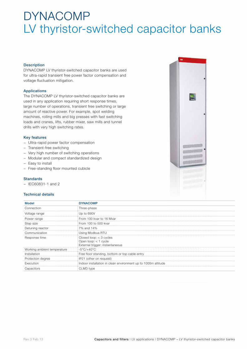
Rev.3 Feb.13 Capacitors and filters | LV applications | DYNACOMP – LV thyristor-switched capacitor banks
DescriptionDYNACOMP LV thyristor-switched capacitor banks are used for ultra-rapid transient free power factor compensation and voltage fluctuation mitigation.
ApplicationsThe DYNACOMP LV thyristor-switched capacitor banks areused in any application requiring short response times, large number of operations, transient free switching or large amount of reactive power. For example, spot welding machines, rolling mills and big presses with fast switching loads and cranes, lifts, rubber mixer, saw mills and tunnel drills with very high switching rates.
Key features − Ultra-rapid power factor compensation − Transient-free switching − Very high number of switching operations − Modular and compact standardized design − Easy to install − Free-standing floor mounted cubicle
Standards − IEC60831-1 and 2
Technical details
DYNACOMPLV thyristor-switched capacitor banks
Model DYNACOMP
Connection Three-phase
Voltage range Up to 690V
Power range From 100 kvar to 16 Mvar
Step size From 100 to 500 kvar
Detuning reactor 7% and 14%
Communication Using Modbus RTU
Response time Closed loop: < 3 cyclesOpen loop: < 1 cycleExternal trigger: instantaneous
Working ambient temperature -5°C/+40°CInstallation Free floor standing, bottom or top cable entry
Protection degree IP21 (other on request)
Execution Indoor installation in clean environment up to 1000m altitude
Capacitors CLMD type
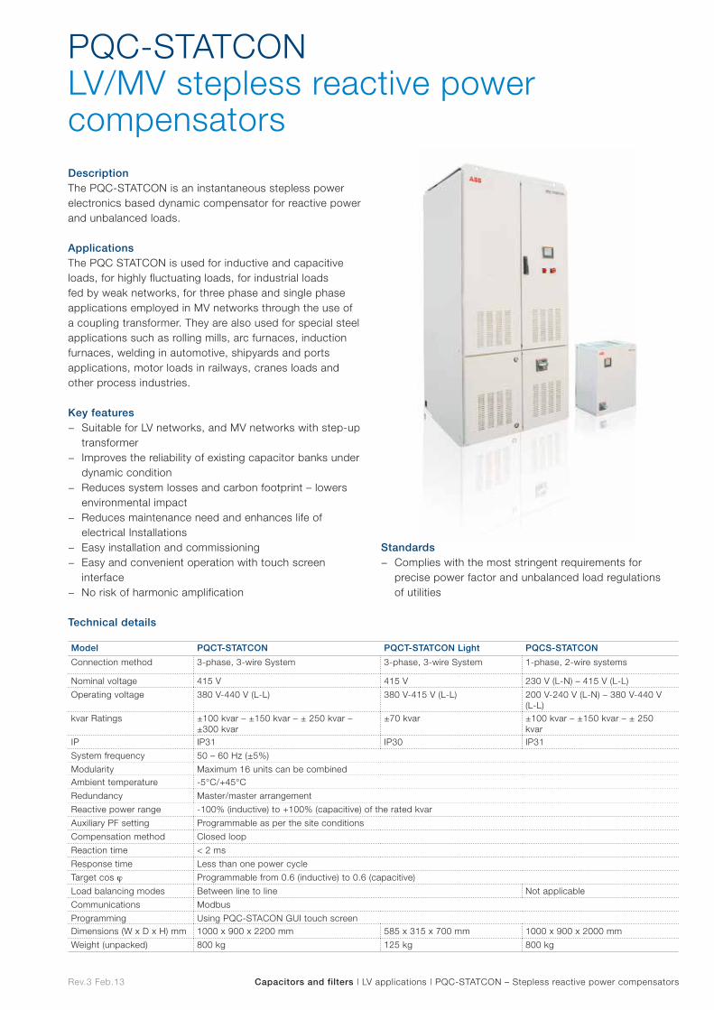
Rev.3 Feb.13 Capacitors and filters | LV applications | PQC-STATCON – Stepless reactive power compensators
DescriptionThe PQC-STATCON is an instantaneous stepless power electronics based dynamic compensator for reactive power and unbalanced loads.
ApplicationsThe PQC STATCON is used for inductive and capacitive loads, for highly fluctuating loads, for industrial loads fed by weak networks, for three phase and single phase applications employed in MV networks through the use of a coupling transformer. They are also used for special steel applications such as rolling mills, arc furnaces, induction furnaces, welding in automotive, shipyards and ports applications, motor loads in railways, cranes loads and other process industries.
Key features − Suitable for LV networks, and MV networks with step-up
transformer − Improves the reliability of existing capacitor banks under
dynamic condition − Reduces system losses and carbon footprint – lowers
environmental impact − Reduces maintenance need and enhances life of
electrical Installations − Easy installation and commissioning − Easy and convenient operation with touch screen
interface − No risk of harmonic amplification
PQC-STATCONLV/MV stepless reactive power compensators
Model PQCT-STATCON PQCT-STATCON Light PQCS-STATCON
Connection method 3-phase, 3-wire System 3-phase, 3-wire System 1-phase, 2-wire systems
Nominal voltage 415 V 415 V 230 V (L-N) – 415 V (L-L)
Operating voltage 380 V-440 V (L-L) 380 V-415 V (L-L) 200 V-240 V (L-N) – 380 V-440 V (L-L)
kvar Ratings ±100 kvar – ±150 kvar – ± 250 kvar – ±300 kvar
±70 kvar ±100 kvar – ±150 kvar – ± 250 kvar
IP IP31 IP30 IP31
System frequency 50 – 60 Hz (±5%)
Modularity Maximum 16 units can be combinedAmbient temperature -5°C/+45°C
Redundancy Master/master arrangement
Reactive power range -100% (inductive) to +100% (capacitive) of the rated kvar
Auxiliary PF setting Programmable as per the site conditions
Compensation method Closed loop
Reaction time < 2 ms
Response time Less than one power cycle
Target cos j Programmable from 0.6 (inductive) to 0.6 (capacitive)
Load balancing modes Between line to line Not applicable
Communications Modbus
Programming Using PQC-STACON GUI touch screenDimensions (W x D x H) mm 1000 x 900 x 2200 mm 585 x 315 x 700 mm 1000 x 900 x 2000 mm
Weight (unpacked) 800 kg 125 kg 800 kg
Standards − Complies with the most stringent requirements for
precise power factor and unbalanced load regulations of utilities
Technical details
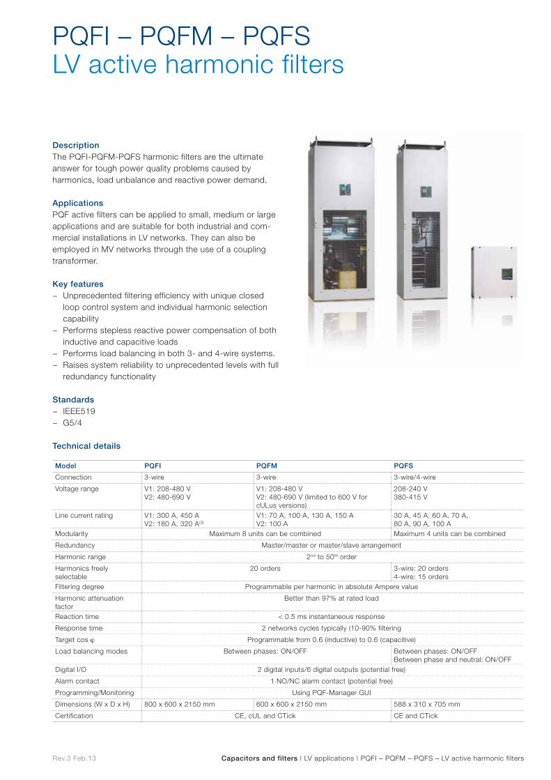
Rev.3 Feb.13 Capacitors and filters | LV applications | PQFI – PQFM – PQFS – LV active harmonic filters
DescriptionThe PQFI-PQFM-PQFS harmonic filters are the ultimate answer for tough power quality problems caused by harmonics, load unbalance and reactive power demand.
ApplicationsPQF active filters can be applied to small, medium or large applications and are suitable for both industrial and com-mercial installations in LV networks. They can also be employed in MV networks through the use of a coupling transformer.
Key features − Unprecedented filtering efficiency with unique closed
loop control system and individual harmonic selection capability
− Performs stepless reactive power compensation of both inductive and capacitive loads
− Performs load balancing in both 3- and 4-wire systems. − Raises system reliability to unprecedented levels with full
redundancy functionality
Standards − IEEE519 − G5/4
Technical details
PQFI – PQFM – PQFSLV active harmonic filters
Model PQFI PQFM PQFS
Connection 3-wire 3-wire 3-wire/4-wire
Voltage range V1: 208-480 VV2: 480-690 V
V1: 208-480 VV2: 480-690 V (limited to 600 V for cULus versions)
208-240 V380-415 V
Line current rating V1: 300 A, 450 AV2: 180 A, 320 A(3)
V1: 70 A, 100 A, 130 A, 150 AV2: 100 A
30 A, 45 A, 60 A, 70 A, 80 A, 90 A, 100 A
Modularity Maximum 8 units can be combined Maximum 4 units can be combined
Redundancy Master/master or master/slave arrangement
Harmonic range 2nd to 50th order
Harmonics freely selectable
20 orders 3-wire: 20 orders4-wire: 15 orders
Filtering degree Programmable per harmonic in absolute Ampere value
Harmonic attenuation factor
Better than 97% at rated load
Reaction time < 0.5 ms instantaneous response
Response time 2 networks cycles typically (10-90% filtering
Target cos j Programmable from 0.6 (inductive) to 0.6 (capacitive)
Load balancing modes Between phases: ON/OFF Between phases: ON/OFFBetween phase and neutral: ON/OFF
Digital I/O 2 digital inputs/6 digital outputs (potential free)
Alarm contact 1 NO/NC alarm contact (potential free)
Programming/Monitoring Using PQF-Manager GUI
Dimensions (W x D x H) 800 x 600 x 2150 mm 600 x 600 x 2150 mm 588 x 310 x 705 mm
Certification CE, cUL and CTick CE and CTick

MV and HV applications MV
and H
V
app
lications
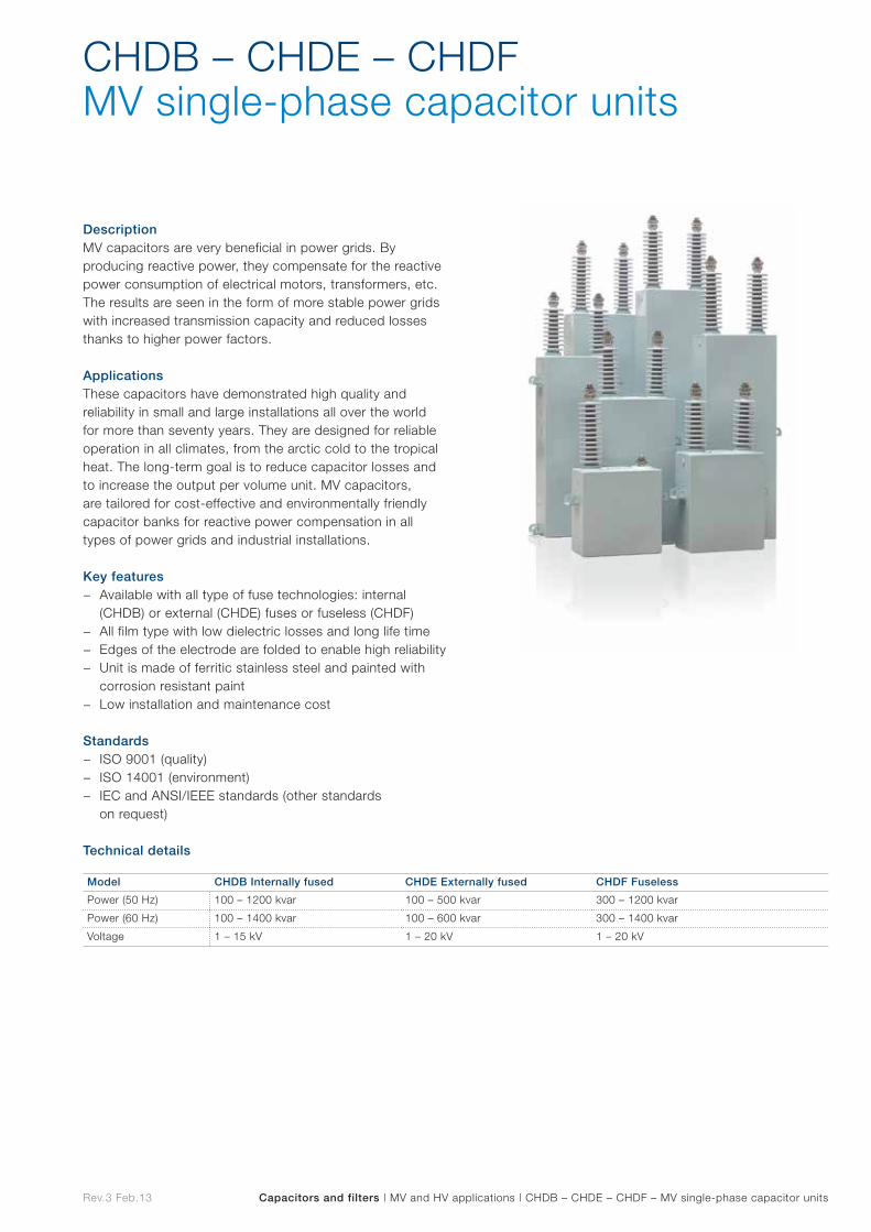
Rev.3 Feb.13 Capacitors and filters | MV and HV applications | CHDB – CHDE – CHDF – MV single-phase capacitor units
DescriptionMV capacitors are very beneficial in power grids. By producing reactive power, they compensate for the reactive power consumption of electrical motors, transformers, etc. The results are seen in the form of more stable power grids with increased transmission capacity and reduced losses thanks to higher power factors.
ApplicationsThese capacitors have demonstrated high quality and reliability in small and large installations all over the world for more than seventy years. They are designed for reliable operation in all climates, from the arctic cold to the tropical heat. The long-term goal is to reduce capacitor losses and to increase the output per volume unit. MV capacitors, are tailored for cost-effective and environmentally friendly capacitor banks for reactive power compensation in all types of power grids and industrial installations.
Key features − Available with all type of fuse technologies: internal
(CHDB) or external (CHDE) fuses or fuseless (CHDF) − All film type with low dielectric losses and long life time − Edges of the electrode are folded to enable high reliability − Unit is made of ferritic stainless steel and painted with
corrosion resistant paint − Low installation and maintenance cost
Standards − ISO 9001 (quality) − ISO 14001 (environment) − IEC and ANSI/IEEE standards (other standards
on request)
Technical details
CHDB – CHDE – CHDFMV single-phase capacitor units
Model CHDB Internally fused CHDE Externally fused CHDF Fuseless
Power (50 Hz) 100 – 1200 kvar 100 – 500 kvar 300 – 1200 kvar
Power (60 Hz) 100 – 1400 kvar 100 – 600 kvar 300 – 1400 kvar
Voltage 1 – 15 kV 1 – 20 kV 1 – 20 kV
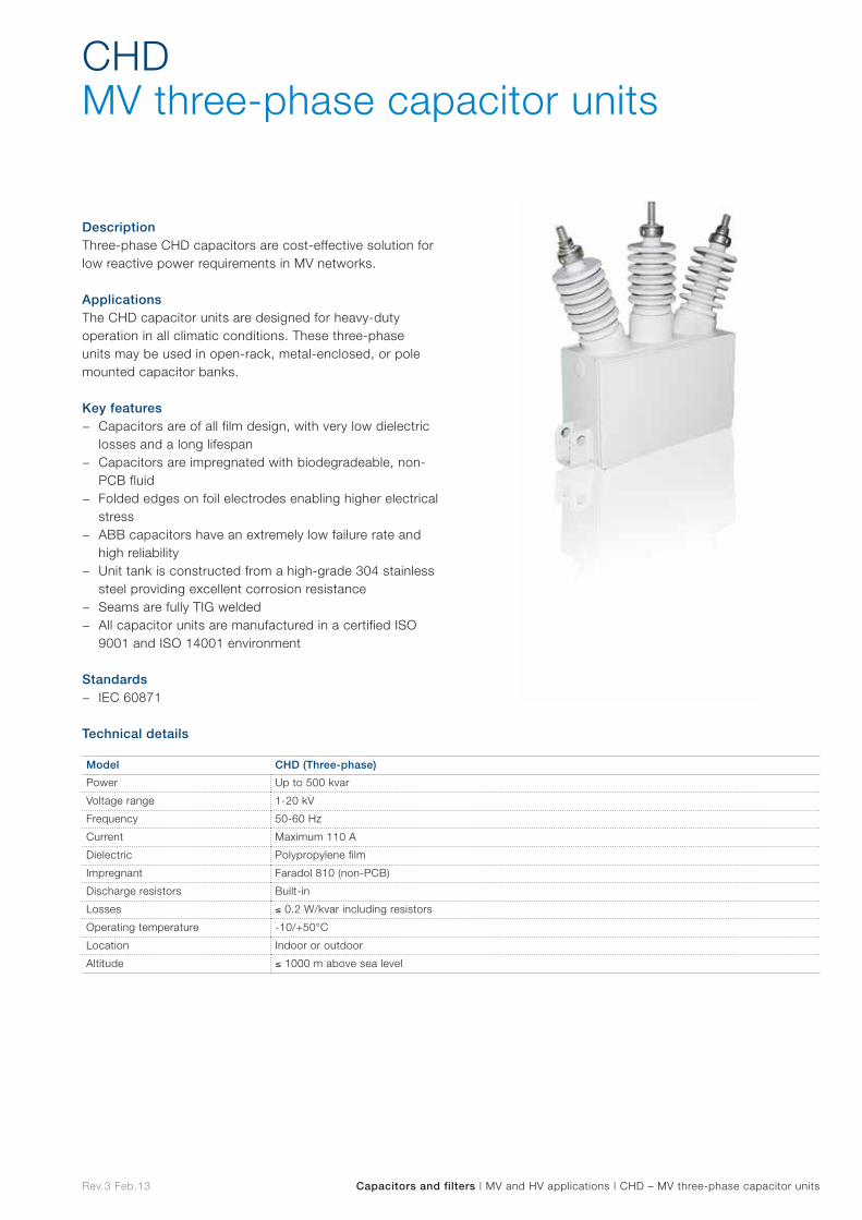
Rev.3 Feb.13 Capacitors and filters | MV and HV applications | CHD – MV three-phase capacitor units
DescriptionThree-phase CHD capacitors are cost-effective solution for low reactive power requirements in MV networks.
ApplicationsThe CHD capacitor units are designed for heavy-duty operation in all climatic conditions. These three-phase units may be used in open-rack, metal-enclosed, or pole mounted capacitor banks.
Key features − Capacitors are of all film design, with very low dielectric
losses and a long lifespan − Capacitors are impregnated with biodegradeable, non-
PCB fluid − Folded edges on foil electrodes enabling higher electrical
stress − ABB capacitors have an extremely low failure rate and
high reliability − Unit tank is constructed from a high-grade 304 stainless
steel providing excellent corrosion resistance − Seams are fully TIG welded − All capacitor units are manufactured in a certified ISO
9001 and ISO 14001 environment
Standards − IEC 60871
Technical details
CHDMV three-phase capacitor units
Model CHD (Three-phase)
Power Up to 500 kvar
Voltage range 1-20 kV
Frequency 50-60 Hz
Current Maximum 110 A
Dielectric Polypropylene film
Impregnant Faradol 810 (non-PCB)
Discharge resistors Built-in
Losses ≤ 0.2 W/kvar including resistors
Operating temperature -10/+50°C
Location Indoor or outdoor
Altitude ≤ 1000 m above sea level
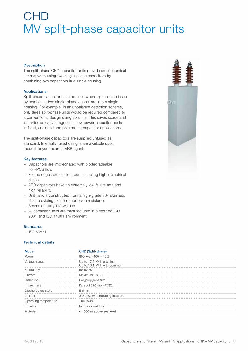
Rev.3 Feb.13 Capacitors and filters | MV and HV applications | CHD – MV capacitor units
DescriptionThe split-phase CHD capacitor units provide an economical alternative to using two single-phase capacitors by combining two capacitors in a single housing.
ApplicationsSplit-phase capacitors can be used where space is an issue by combining two single-phase capacitors into a single housing. For example, in an unbalance detection scheme, only three split-phase units would be required compared to a conventional design using six units. This saves space and is particularly advantageous in low power capacitor banks in fixed, enclosed and pole mount capacitor applications.
The split-phase capacitors are supplied unfused as standard. Internally fused designs are available upon request to your nearest ABB agent.
Key features − Capacitors are impregnated with biodegradeable,
non-PCB fluid − Folded edges on foil electrodes enabling higher electrical
stress − ABB capacitors have an extremely low failure rate and
high reliability − Unit tank is constructed from a high-grade 304 stainless
steel providing excellent corrosion resistance − Seams are fully TIG welded − All capacitor units are manufactured in a certified ISO
9001 and ISO 14001 environment
Standards − IEC 60871
Technical details
CHDMV split-phase capacitor units
Model CHD (Split-phase)
Power 800 kvar (400 + 400)
Voltage range Up to 17.5 kV line to lineUp to 10.1 kV line to common
Frequency 50-60 Hz
Current Maximum 180 A
Dielectric Polypropylene film
Impregnant Faradol 810 (non-PCB)
Discharge resistors Built-in
Losses ≤ 0.2 W/kvar including resistors
Operating temperature -10/+50°C
Location Indoor or outdoor
Altitude ≤ 1000 m above sea level
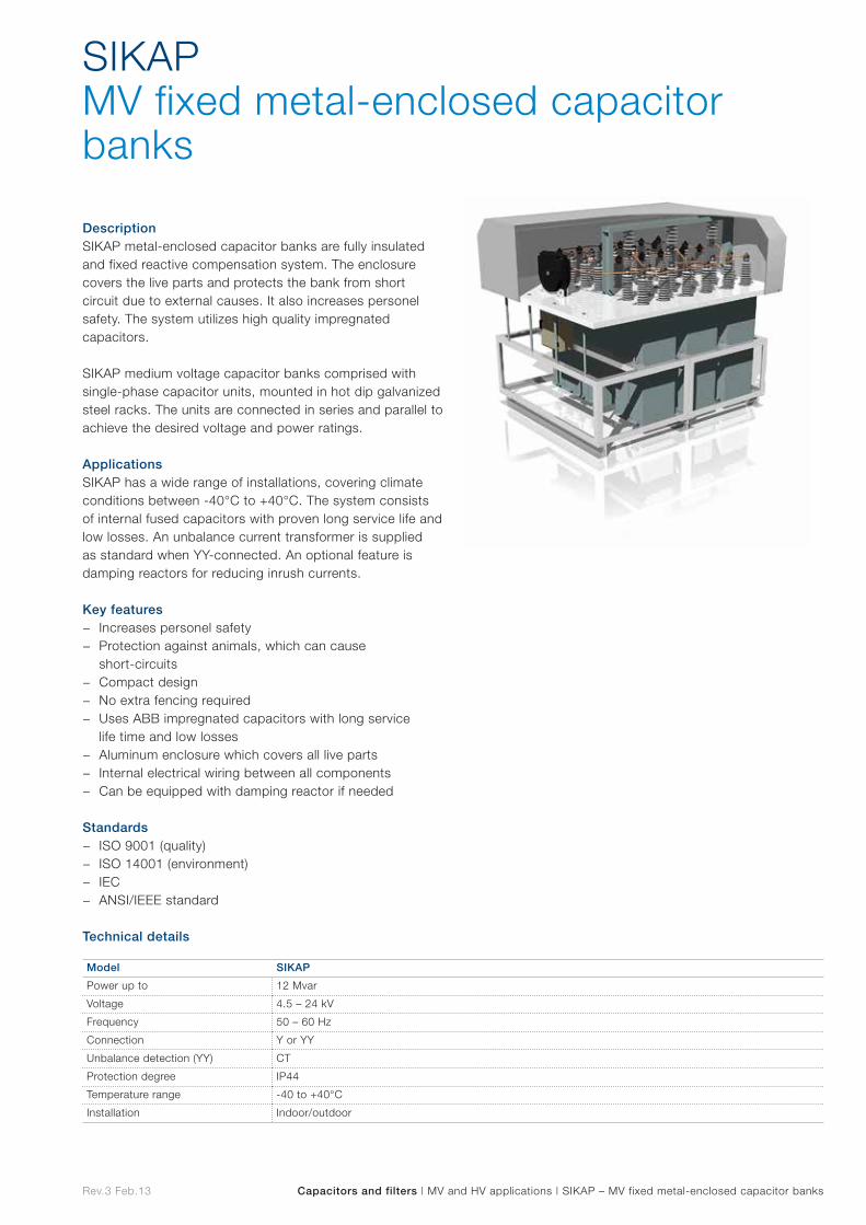
Rev.3 Feb.13 Capacitors and filters | MV and HV applications | SIKAP – MV fixed metal-enclosed capacitor banks
DescriptionSIKAP metal-enclosed capacitor banks are fully insulated and fixed reactive compensation system. The enclosure covers the live parts and protects the bank from short circuit due to external causes. It also increases personel safety. The system utilizes high quality impregnated capacitors.
SIKAP medium voltage capacitor banks comprised with single-phase capacitor units, mounted in hot dip galvanized steel racks. The units are connected in series and parallel to achieve the desired voltage and power ratings.
ApplicationsSIKAP has a wide range of installations, covering climate conditions between -40°C to +40°C. The system consists of internal fused capacitors with proven long service life and low losses. An unbalance current transformer is supplied as standard when YY-connected. An optional feature is damping reactors for reducing inrush currents.
Key features − Increases personel safety − Protection against animals, which can cause
short-circuits − Compact design − No extra fencing required − Uses ABB impregnated capacitors with long service
life time and low losses − Aluminum enclosure which covers all live parts − Internal electrical wiring between all components − Can be equipped with damping reactor if needed
Standards − ISO 9001 (quality) − ISO 14001 (environment) − IEC − ANSI/IEEE standard
Technical details
SIKAPMV fixed metal-enclosed capacitor banks
Model SIKAP
Power up to 12 Mvar
Voltage 4.5 – 24 kV
Frequency 50 – 60 Hz
Connection Y or YY
Unbalance detection (YY) CT
Protection degree IP44
Temperature range -40 to +40°C
Installation Indoor/outdoor
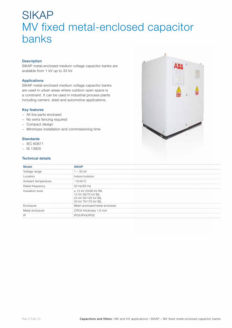
Rev.3 Feb.13 Capacitors and filters | MV and HV applications | SIKAP – MV fixed metal-enclosed capacitor banks
DescriptionSIKAP metal-enclosed medium voltage capacitor banks are available from 1 kV up to 33 kV.
ApplicationsSIKAP metal-enclosed medium voltage capacitor banks are used in urban areas where outdoor open space is a constraint. It can be used in industrial process plants including cement, steel and automotive applications.
Key features − All live parts enclosed − No extra fencing required − Compact design − Minimizes installation and commissioning time
Standards − IEC 60871 − IS 13925
Technical details
SIKAPMV fixed metal-enclosed capacitor banks
Model SIKAP
Voltage range 1 – 33 kV
Location Indoor/outdoor
Ambient temperature -10/45°C
Rated frequency 50 Hz/60 Hz
Insulation level ≤ 12 kV 20/60 kV BIL 12 kV 28/75 kV BIL24 kV 50/125 kV BIL 33 kV 70/170 kV BIL
Enclosure Mesh enclosed/metal-enclosed
Metal enclosure CRCA thickness 1.6 mm
IP IP2X/IP4X/IP5X

Rev.3 Feb.13 Capacitors and filters | MV and HV applications | EMPAC – MV fixed metal-enclosed capacitor banks
DescriptionEMPAC MV fixed metal-enclosed capacitor banks in double star configuration are used for distribution substations and wind farms.
ApplicationsEMPAC is designed for indoor/outdoor substations where space is an issue. They are available with an SF6 circuit breaker or without a circuit breaker depending on customer needs.
Key features − Compact design resulting in a small footprint and height. − Fully enclosed design protecting live parts. Interlocking
scheme between circuit breaker and grounding switch is always fitted for personel protection. Live line indicators as well an integral interlocking scheme are also available on request
− Same footprint and volume in case of Mvar expansion − Very easy handling and lifting. No additional assembly
required on site − SF6 breaker mechanically staggered for synchronized
switching where switching transients are critical (optional) − Very easy replacement of components in the event of
failure or malfunction
Standards − IEC standards
Technical details
EMPACMV fixed metal-enclosed capacitor banks
Model EMPAC
Rated voltage From 1 kV to 36 kV
Maximum output 10.6 MVAr at 24 kV/16 MVAr at 36 kV
Capacitor configuration Double Star/single star (on request)
IP rating IP23 – IP44
Frequency 50 or 60 Hz
Standard IEC or equivalent
Location Indoor or outdoor
Temperature -25 ºC up to +55°C
Short circuit current 40 kA for 1s
Circuit breaker SF6 – 3 pole
Inrush reactors Epoxi resin cast
Current transformers Epoxi resin cast – X/5 A
Earth switch Air insulated
Optional Fast discharge reactorsLive line indicationProtection relay
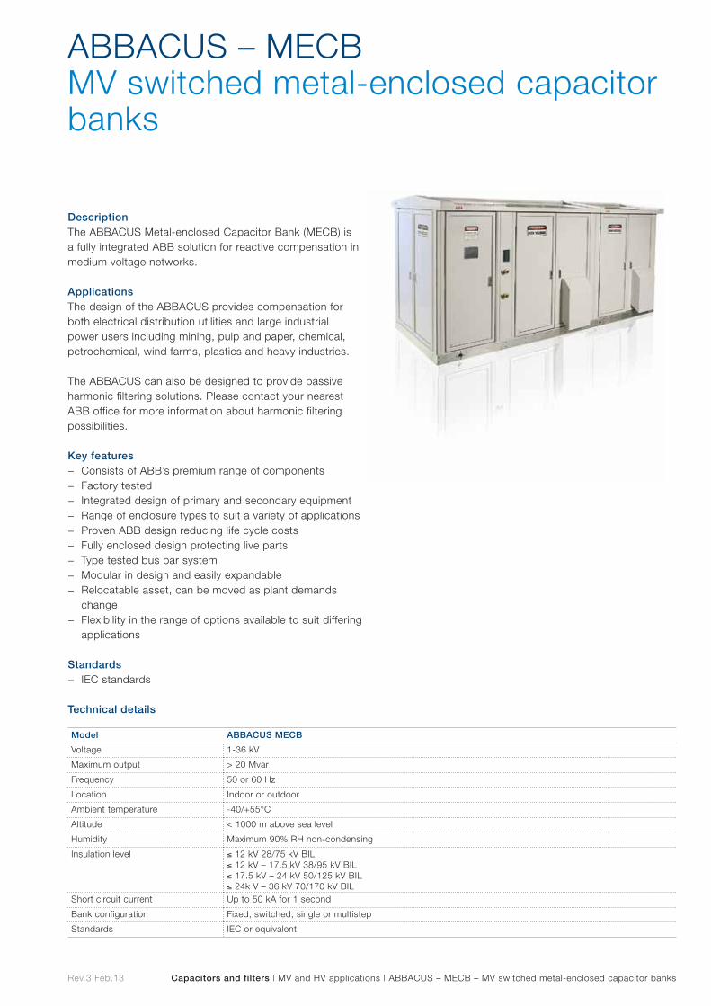
Rev.3 Feb.13 Capacitors and filters | MV and HV applications | ABBACUS – MECB – MV switched metal-enclosed capacitor banks
DescriptionThe ABBACUS Metal-enclosed Capacitor Bank (MECB) is a fully integrated ABB solution for reactive compensation in medium voltage networks.
ApplicationsThe design of the ABBACUS provides compensation for both electrical distribution utilities and large industrial power users including mining, pulp and paper, chemical, petrochemical, wind farms, plastics and heavy industries.
The ABBACUS can also be designed to provide passive harmonic filtering solutions. Please contact your nearest ABB office for more information about harmonic filtering possibilities.
Key features − Consists of ABB’s premium range of components − Factory tested − Integrated design of primary and secondary equipment − Range of enclosure types to suit a variety of applications − Proven ABB design reducing life cycle costs − Fully enclosed design protecting live parts − Type tested bus bar system − Modular in design and easily expandable − Relocatable asset, can be moved as plant demands
change − Flexibility in the range of options available to suit differing
applications
Standards − IEC standards
Technical details
ABBACUS – MECBMV switched metal-enclosed capacitor banks
Model ABBACUS MECB
Voltage 1-36 kV
Maximum output > 20 Mvar
Frequency 50 or 60 Hz
Location Indoor or outdoor
Ambient temperature -40/+55°C
Altitude < 1000 m above sea level
Humidity Maximum 90% RH non-condensing
Insulation level ≤ 12 kV 28/75 kV BIL≤ 12 kV – 17.5 kV 38/95 kV BIL≤ 17.5 kV – 24 kV 50/125 kV BIL≤ 24k V – 36 kV 70/170 kV BIL
Short circuit current Up to 50 kA for 1 second
Bank configuration Fixed, switched, single or multistep
Standards IEC or equivalent
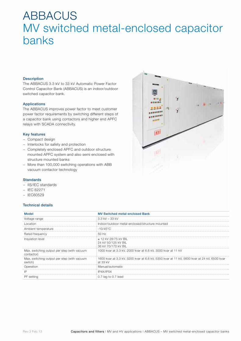
Rev.3 Feb.13 Capacitors and filters | MV and HV applications | ABBACUS – MV switched metal-enclosed capacitor banks
DescriptionThe ABBACUS 3.3 kV to 33 kV Automatic Power Factor Control Capacitor Bank (ABBACUS) is an indoor/outdoor switched capacitor bank.
ApplicationsThe ABBACUS improves power factor to meet customer power factor requirements by switching different steps of a capacitor bank using contactors and higher end APFC relays with SCADA connectivity.
Key features − Compact design − Interlocks for safety and protection − Completely enclosed APFC and outdoor structure
mounted APFC system and also semi enclosed with structure mounted banks
− More than 100,000 switching operations with ABB vacuum contactor technology
Standards − IIS/IEC standards − IEC 62271 − IEC60529
Technical details
ABBACUSMV switched metal-enclosed capacitor banks
Model MV Switched metal-enclosed Bank
Voltage range 3.3 kV – 33 kV
Location Indoor/outdoor metal-enclosed/structure mounted
Ambient temperature -10/45°C
Rated frequency 50 Hz
Insulation level ≤ 12 kV 28/75 kV BIL 24 kV 50/125 kV BIL 36 kV 70/170 kV BIL
Max. switching output per step (with vacuum contactor)
1000 kvar at 3.3 kV, 2000 kvar at 6.6 kV, 3000 kvar at 11 kV
Max. switching output per step (with vacuum switch)
1600 kvar at 3.3 kV, 3200 kvar at 6.6 kV, 5350 kvar at 11 kV, 5600 kvar at 24 kV, 6500 kvar at 33 kV
Operation Manual/automatic
IP IP4X/IP5X
PF setting 0.7 lag to 0.7 lead
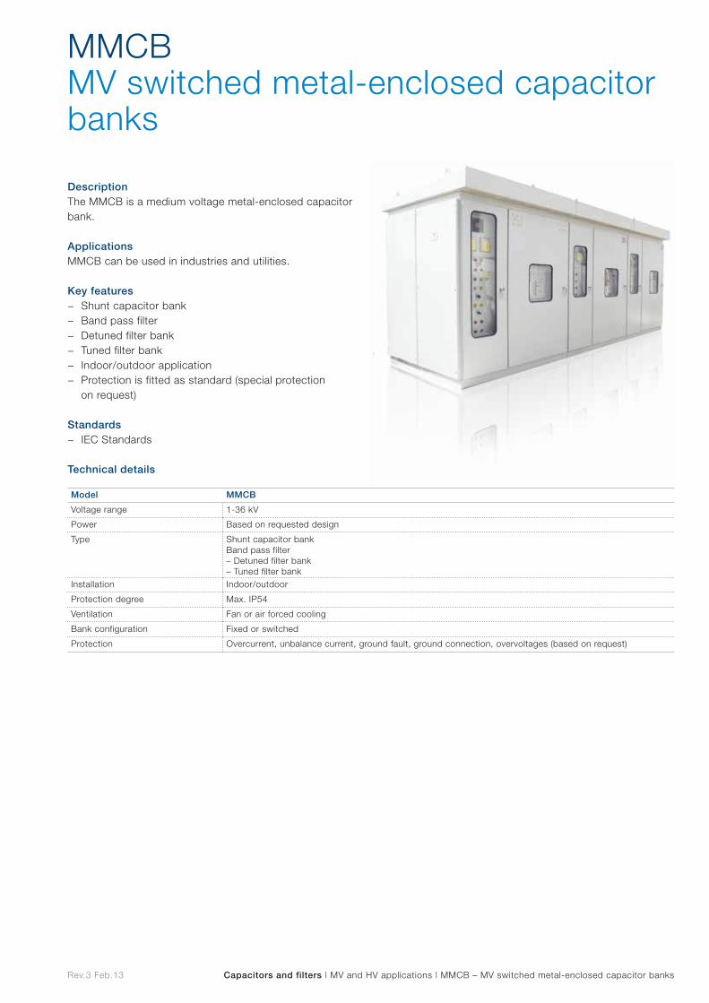
Rev.3 Feb.13 Capacitors and filters | MV and HV applications | MMCB – MV switched metal-enclosed capacitor banks
DescriptionThe MMCB is a medium voltage metal-enclosed capacitor bank.
ApplicationsMMCB can be used in industries and utilities.
Key features − Shunt capacitor bank − Band pass filter − Detuned filter bank − Tuned filter bank − Indoor/outdoor application − Protection is fitted as standard (special protection
on request)
Standards − IEC Standards
Technical details
MMCBMV switched metal-enclosed capacitor banks
Model MMCB
Voltage range 1-36 kV
Power Based on requested design
Type Shunt capacitor bankBand pass filter– Detuned filter bank– Tuned filter bank
Installation Indoor/outdoor
Protection degree Max. IP54
Ventilation Fan or air forced cooling
Bank configuration Fixed or switched
Protection Overcurrent, unbalance current, ground fault, ground connection, overvoltages (based on request)
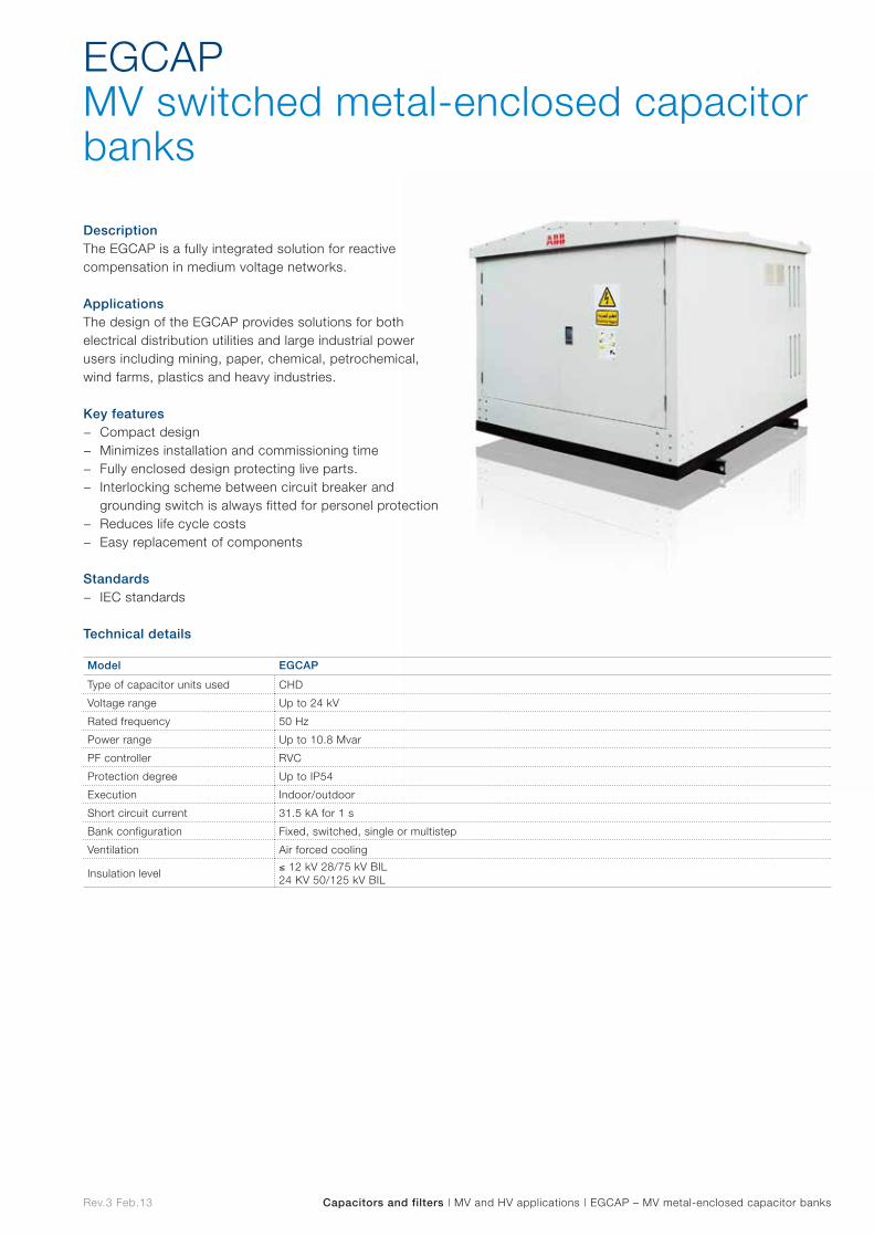
Rev.3 Feb.13 Capacitors and filters | MV and HV applications | EGCAP – MV metal-enclosed capacitor banks
DescriptionThe EGCAP is a fully integrated solution for reactive compensation in medium voltage networks.
ApplicationsThe design of the EGCAP provides solutions for both electrical distribution utilities and large industrial power users including mining, paper, chemical, petrochemical, wind farms, plastics and heavy industries.
Key features − Compact design − Minimizes installation and commissioning time − Fully enclosed design protecting live parts. − Interlocking scheme between circuit breaker and
grounding switch is always fitted for personel protection − Reduces life cycle costs − Easy replacement of components
Standards − IEC standards
Technical details
EGCAPMV switched metal-enclosed capacitor banks
Model EGCAP
Type of capacitor units used CHD
Voltage range Up to 24 kV
Rated frequency 50 Hz
Power range Up to 10.8 Mvar
PF controller RVC
Protection degree Up to IP54
Execution Indoor/outdoor
Short circuit current 31.5 kA for 1 s
Bank configuration Fixed, switched, single or multistep
Ventilation Air forced cooling
Insulation level≤ 12 kV 28/75 kV BIL24 KV 50/125 kV BIL
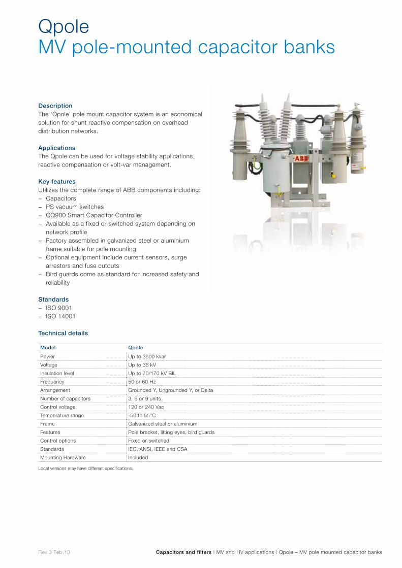
Rev.3 Feb.13 Capacitors and filters | MV and HV applications | Qpole – MV pole mounted capacitor banks
DescriptionThe ‘Qpole’ pole mount capacitor system is an economical solution for shunt reactive compensation on overhead distribution networks.
ApplicationsThe Qpole can be used for voltage stability applications, reactive compensation or volt-var management.
Key featuresUtilizes the complete range of ABB components including:
− Capacitors − PS vacuum switches − CQ900 Smart Capacitor Controller − Available as a fixed or switched system depending on
network profile − Factory assembled in galvanized steel or aluminium
frame suitable for pole mounting − Optional equipment include current sensors, surge
arrestors and fuse cutouts − Bird guards come as standard for increased safety and
reliability
Standards − ISO 9001 − ISO 14001
Technical details
QpoleMV pole-mounted capacitor banks
Model Qpole
Power Up to 3600 kvar
Voltage Up to 36 kV
Insulation level Up to 70/170 kV BIL
Frequency 50 or 60 Hz
Arrangement Grounded Y, Ungrounded Y, or Delta
Number of capacitors 3, 6 or 9 units
Control voltage 120 or 240 Vac
Temperature range -50 to 55°C
Frame Galvanized steel or aluminium
Features Pole bracket, lifting eyes, bird guards
Control options Fixed or switched
Standards IEC, ANSI, IEEE and CSA
Mounting Hardware Included
Local versions may have different specifications.
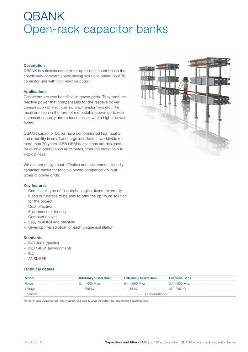
Rev.3 Feb.13 Capacitors and filters | MV and HV applications | QBANK – open-rack capacitor banks
DescriptionQBANK is a flexible concept for open-rack shunt banks that enable very compact space saving solutions based on ABB capacitor unit with high reactive output.
ApplicationsCapacitors are very beneficial in power grids. They produce reactive power that compensates for the reactive power consumption of electrical motors, transformers etc. The result are seen in the form of more stable power grids with increased capacity and reduced losses with a higher power factor.
QBANK capacitor banks have demonstrated high quality and reliability in small and large installations worldwide for more than 70 years. ABB QBANK solutions are designed for reliable operation in all climates, from the arctic cold to tropical heat.
We custom design cost-effective and environment-friendly capacitor banks for reactive power compensation in all types of power grids.
Key features − Can use all type of fuse technologies, fused, externally
fused or fuseless to be able to offer the optimum solution for the project
− Cost effective − Environmental-friendly − Compact design − Easy to install and maintain − Gives optimal solution for each unique installation
Standards − ISO 9001 (quality) − ISO 14001 (environment) − IEC − ANSI/IEEE
Technical details
QBANKOpen-rack capacitor banks
Model Internally fused Bank Externally fused Bank Fuseless Bank
Power 0.1 – 600 Mvar 0.1 – 600 Mvar 0.1 – 600 Mvar
Voltage 1 – 765 kV 1 – 35 kV 35 – 765 kV
Location Outdoor/Indoor
For other data please consult your nearest ABB agent. Local versions may have different specifications.
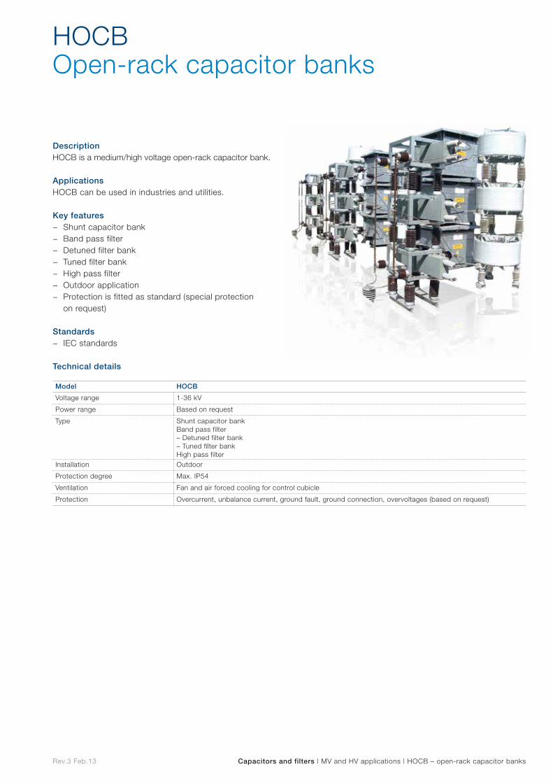
Rev.3 Feb.13 Capacitors and filters | MV and HV applications | HOCB – open-rack capacitor banks
DescriptionHOCB is a medium/high voltage open-rack capacitor bank.
ApplicationsHOCB can be used in industries and utilities.
Key features − Shunt capacitor bank − Band pass filter − Detuned filter bank − Tuned filter bank − High pass filter − Outdoor application − Protection is fitted as standard (special protection
on request)
Standards − IEC standards
Technical details
HOCBOpen-rack capacitor banks
Model HOCB
Voltage range 1-36 kV
Power range Based on request
Type Shunt capacitor bankBand pass filter– Detuned filter bank– Tuned filter bankHigh pass filter
Installation Outdoor
Protection degree Max. IP54
Ventilation Fan and air forced cooling for control cubicle
Protection Overcurrent, unbalance current, ground fault, ground connection, overvoltages (based on request)
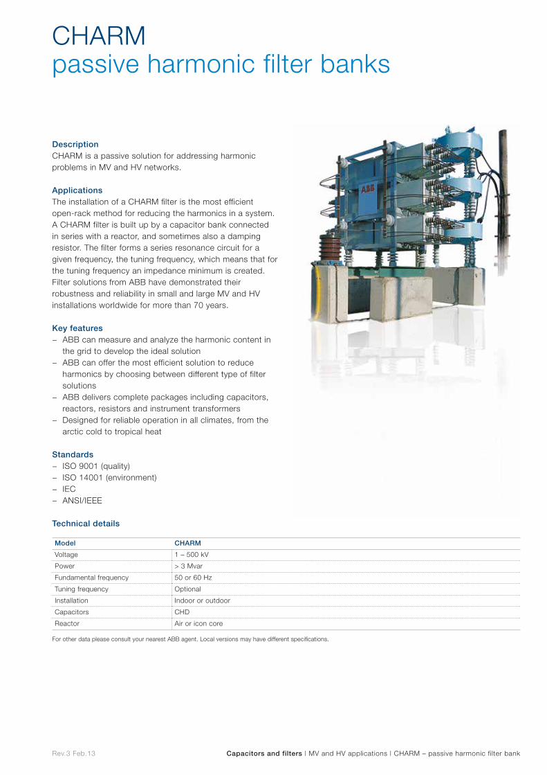
Rev.3 Feb.13 Capacitors and filters | MV and HV applications | CHARM – passive harmonic filter bank
DescriptionCHARM is a passive solution for addressing harmonic problems in MV and HV networks.
ApplicationsThe installation of a CHARM filter is the most efficient open-rack method for reducing the harmonics in a system. A CHARM filter is built up by a capacitor bank connected in series with a reactor, and sometimes also a damping resistor. The filter forms a series resonance circuit for a given frequency, the tuning frequency, which means that for the tuning frequency an impedance minimum is created. Filter solutions from ABB have demonstrated their robustness and reliability in small and large MV and HV installations worldwide for more than 70 years.
Key features − ABB can measure and analyze the harmonic content in
the grid to develop the ideal solution − ABB can offer the most efficient solution to reduce
harmonics by choosing between different type of filter solutions
− ABB delivers complete packages including capacitors, reactors, resistors and instrument transformers
− Designed for reliable operation in all climates, from the arctic cold to tropical heat
Standards − ISO 9001 (quality) − ISO 14001 (environment) − IEC − ANSI/IEEE
Technical details
CHARMpassive harmonic filter banks
Model CHARM
Voltage 1 – 500 kV
Power > 3 Mvar
Fundamental frequency 50 or 60 Hz
Tuning frequency Optional
Installation Indoor or outdoor
Capacitors CHD
Reactor Air or icon core
For other data please consult your nearest ABB agent. Local versions may have different specifications.

Switches and accessories
Sw
itches and
accessories
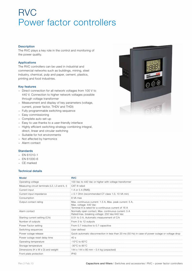
Rev.3 Feb.13 Capacitors and filters | Switches and accessories | RVC – power factor controllers
DescriptionThe RVC plays a key role in the control and monitoring of the power quality.
ApplicationsThe RVC controllers can be used in industrial and commercial networks such as buildings, mining, steel industry, chemical, pulp and paper, cement, plastics, printing and food industries.
Key features − Direct connection for all network voltages from 100 V to
440 V. Connection to higher network voltages possible through voltage transformer
− Measurement and display of key parameters (voltage, current, power factor, THDV and THDI)
− Fully programmable switching sequence − Easy commissioning − Complete auto set-up − Easy to use thanks to a user-friendly interface − Highly efficient switching strategy combining integral,
direct, linear and circular switching − Suitable for hot environments − Not affected by harmonics − Alarm contact
Standards − EN 61010-1 − EN 61000-6 − CE marked
Technical details
RVCPower factor controllers
Model RVC
Operating voltage 100 Vac to 440 Vac or higher with voltage transformer
Measuring circuit terminals (L2, L3 and k, I) CAT III rated
Current input 1 A or 5 A (RMS)
Current input impedance < 0.1 Ohm (recommended CT class 1.0, 10 VA min)
Consumption 8 VA max
Output contact rating Max. continuous current: 1.5 A, Max. peak current: 5 A, Max. voltage: 440 VacTerminal A is rated for a continuous current of 16 A
Alarm contact Normally open contact, Max. continuous current: 5 ARated/max. breaking voltage: 250 Vac/440 Vac
Starting current setting (C/k) 0.01 to 3 A, Automatic measurement of C/k
Number of outputs From 3 to 12 outputs
Power Factor setting From 0.7 inductive to 0.7 capacitive
Switching sequences User defined
Power outage release Quick automatic disconnection in less than 20 ms (50 Hz) in case of power outage or voltage drop
Power outage reset delay time 40 s
Operating temperature -10°C to 60°C
Storage temperature -30°C to 85°C
Dimensions (H x W x D) and weight 144 x 144 x 80 mm – 0.4 kg (unpacked)
Front plate protection IP40
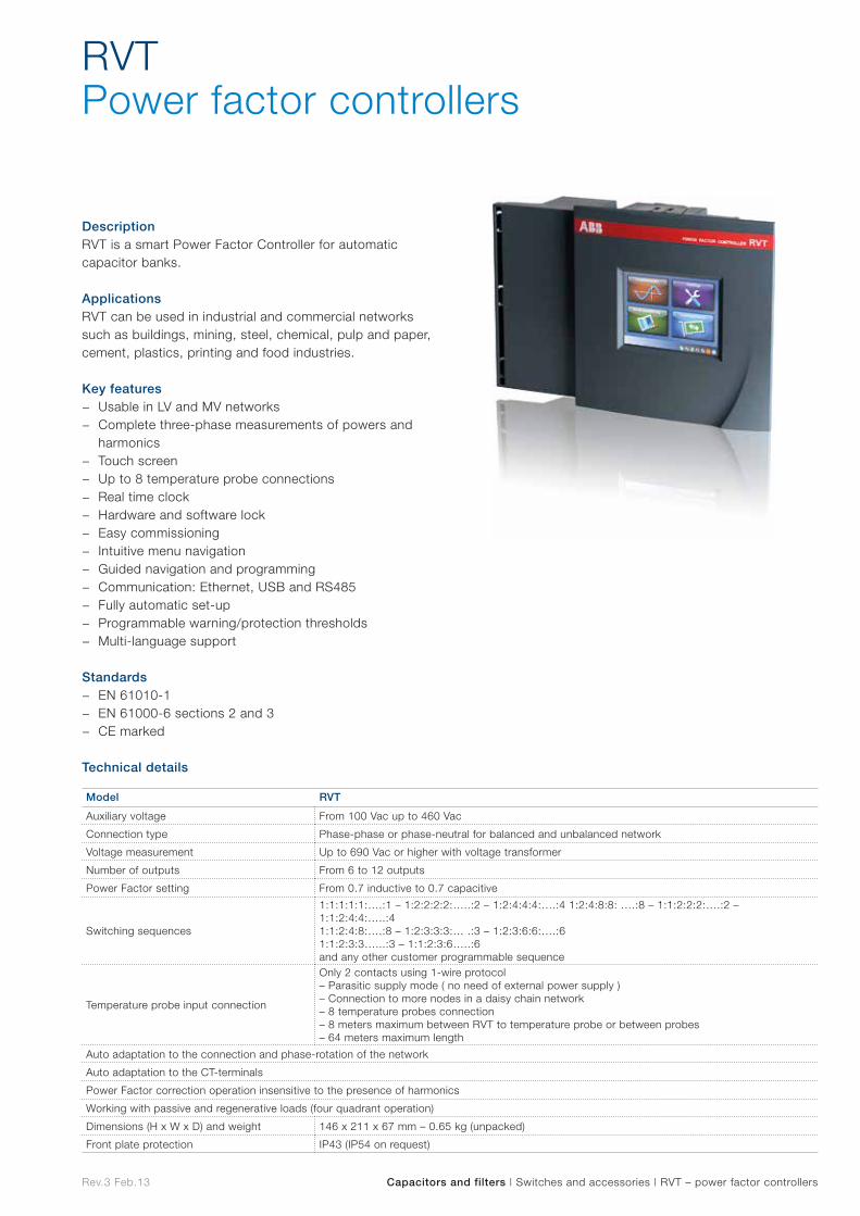
Rev.3 Feb.13 Capacitors and filters | Switches and accessories | RVT – power factor controllers
DescriptionRVT is a smart Power Factor Controller for automatic capacitor banks.
ApplicationsRVT can be used in industrial and commercial networks such as buildings, mining, steel, chemical, pulp and paper, cement, plastics, printing and food industries.
Key features − Usable in LV and MV networks − Complete three-phase measurements of powers and
harmonics − Touch screen − Up to 8 temperature probe connections − Real time clock − Hardware and software lock − Easy commissioning − Intuitive menu navigation − Guided navigation and programming − Communication: Ethernet, USB and RS485 − Fully automatic set-up − Programmable warning/protection thresholds − Multi-language support
Standards − EN 61010-1 − EN 61000-6 sections 2 and 3 − CE marked
Technical details
RVTPower factor controllers
Model RVT
Auxiliary voltage From 100 Vac up to 460 Vac
Connection type Phase-phase or phase-neutral for balanced and unbalanced network
Voltage measurement Up to 690 Vac or higher with voltage transformer
Number of outputs From 6 to 12 outputs
Power Factor setting From 0.7 inductive to 0.7 capacitive
Switching sequences
1:1:1:1:1:….:1 – 1:2:2:2:2:…..:2 – 1:2:4:4:4:….:4 1:2:4:8:8: ….:8 – 1:1:2:2:2:….:2 – 1:1:2:4:4:…..:4 1:1:2:4:8:….:8 – 1:2:3:3:3:… .:3 – 1:2:3:6:6:….:6 1:1:2:3:3…...:3 – 1:1:2:3:6…..:6 and any other customer programmable sequence
Temperature probe input connection
Only 2 contacts using 1-wire protocol – Parasitic supply mode ( no need of external power supply ) – Connection to more nodes in a daisy chain network – 8 temperature probes connection – 8 meters maximum between RVT to temperature probe or between probes – 64 meters maximum length
Auto adaptation to the connection and phase-rotation of the network
Auto adaptation to the CT-terminals
Power Factor correction operation insensitive to the presence of harmonics
Working with passive and regenerative loads (four quadrant operation)
Dimensions (H x W x D) and weight 146 x 211 x 67 mm – 0.65 kg (unpacked)
Front plate protection IP43 (IP54 on request)
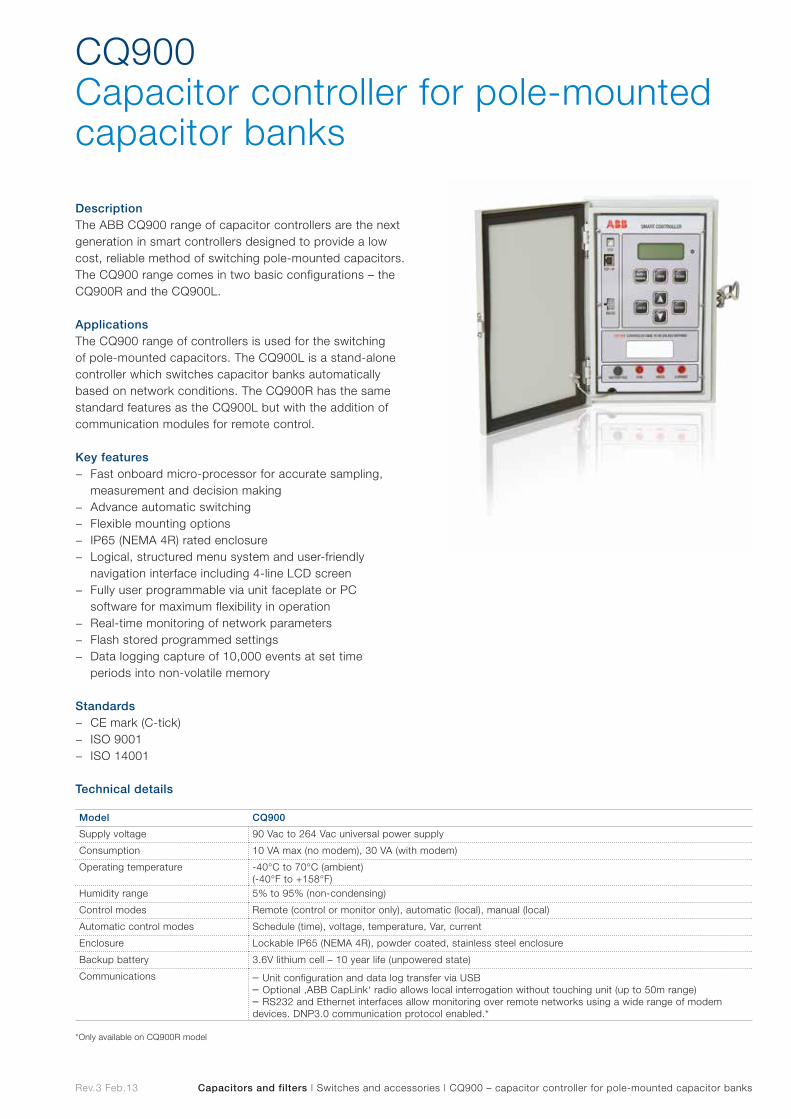
Rev.3 Feb.13 Capacitors and filters | Switches and accessories | CQ900 – capacitor controller for pole-mounted capacitor banks
DescriptionThe ABB CQ900 range of capacitor controllers are the next generation in smart controllers designed to provide a low cost, reliable method of switching pole-mounted capacitors. The CQ900 range comes in two basic configurations – the CQ900R and the CQ900L.
ApplicationsThe CQ900 range of controllers is used for the switching of pole-mounted capacitors. The CQ900L is a stand-alone controller which switches capacitor banks automatically based on network conditions. The CQ900R has the same standard features as the CQ900L but with the addition of communication modules for remote control.
Key features − Fast onboard micro-processor for accurate sampling,
measurement and decision making − Advance automatic switching − Flexible mounting options − IP65 (NEMA 4R) rated enclosure − Logical, structured menu system and user-friendly
navigation interface including 4-line LCD screen − Fully user programmable via unit faceplate or PC
software for maximum flexibility in operation − Real-time monitoring of network parameters − Flash stored programmed settings − Data logging capture of 10,000 events at set time
periods into non-volatile memory
Standards − CE mark (C-tick) − ISO 9001 − ISO 14001
Technical details
CQ900Capacitor controller for pole-mounted capacitor banks
Model CQ900
Supply voltage 90 Vac to 264 Vac universal power supply
Consumption 10 VA max (no modem), 30 VA (with modem)
Operating temperature -40°C to 70°C (ambient)(-40°F to +158°F)
Humidity range 5% to 95% (non-condensing)
Control modes Remote (control or monitor only), automatic (local), manual (local)
Automatic control modes Schedule (time), voltage, temperature, Var, current
Enclosure Lockable IP65 (NEMA 4R), powder coated, stainless steel enclosure
Backup battery 3.6V lithium cell – 10 year life (unpowered state)
Communications – Unit configuration and data log transfer via USB– Optional ‚ABB CapLink‘ radio allows local interrogation without touching unit (up to 50m range)– RS232 and Ethernet interfaces allow monitoring over remote networks using a wide range of modem devices. DNP3.0 communication protocol enabled.*
*Only available on CQ900R model
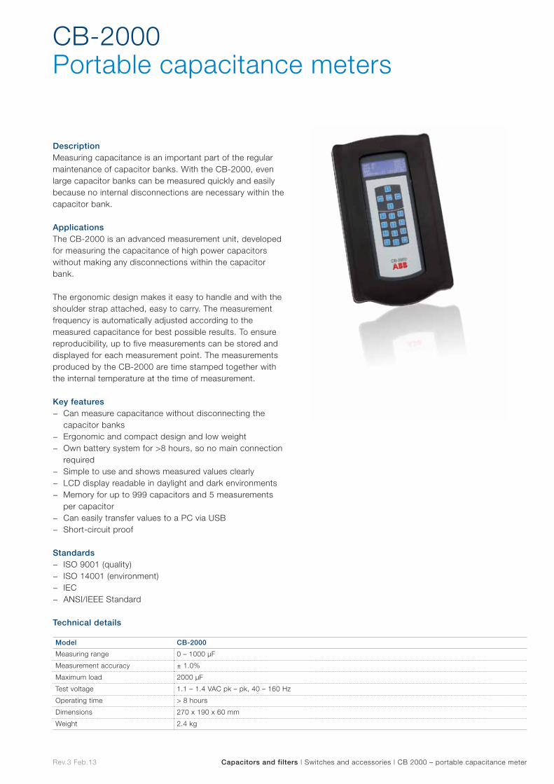
Rev.3 Feb.13 Capacitors and filters | Switches and accessories | CB 2000 – portable capacitance meter
DescriptionMeasuring capacitance is an important part of the regular maintenance of capacitor banks. With the CB-2000, even large capacitor banks can be measured quickly and easily because no internal disconnections are necessary within the capacitor bank.
ApplicationsThe CB-2000 is an advanced measurement unit, developed for measuring the capacitance of high power capacitors without making any disconnections within the capacitor bank.
The ergonomic design makes it easy to handle and with the shoulder strap attached, easy to carry. The measurement frequency is automatically adjusted according to the measured capacitance for best possible results. To ensure reproducibility, up to five measurements can be stored and displayed for each measurement point. The measurements produced by the CB-2000 are time stamped together with the internal temperature at the time of measurement. Key features
− Can measure capacitance without disconnecting the capacitor banks
− Ergonomic and compact design and low weight − Own battery system for >8 hours, so no main connection
required − Simple to use and shows measured values clearly − LCD display readable in daylight and dark environments − Memory for up to 999 capacitors and 5 measurements
per capacitor − Can easily transfer values to a PC via USB − Short-circuit proof
Standards − ISO 9001 (quality) − ISO 14001 (environment) − IEC − ANSI/IEEE Standard
Technical details
CB-2000Portable capacitance meters
Model CB-2000
Measuring range 0 – 1000 µF
Measurement accuracy ± 1.0%
Maximum load 2000 µF
Test voltage 1.1 – 1.4 VAC pk – pk, 40 – 160 Hz
Operating time > 8 hours
Dimensions 270 x 190 x 60 mm
Weight 2.4 kg

Control and protection devices
Co
ntrol and
p
rotectio
n d
evices
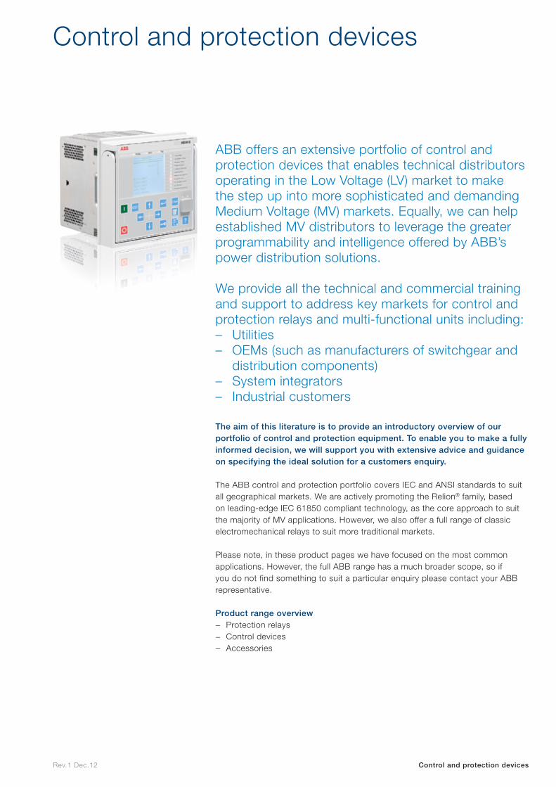
Rev.1 Dec.12 Control and protection devices
ABB offers an extensive portfolio of control and protection devices that enables technical distributors operating in the Low Voltage (LV) market to make the step up into more sophisticated and demanding Medium Voltage (MV) markets. Equally, we can help established MV distributors to leverage the greater programmability and intelligence offered by ABB’s power distribution solutions.
We provide all the technical and commercial training and support to address key markets for control and protection relays and multi-functional units including: – Utilities – OEMs (such as manufacturers of switchgear and
distribution components) – System integrators – Industrial customers
The aim of this literature is to provide an introductory overview of our portfolio of control and protection equipment. To enable you to make a fully informed decision, we will support you with extensive advice and guidance on specifying the ideal solution for a customers enquiry.
The ABB control and protection portfolio covers IEC and ANSI standards to suit all geographical markets. We are actively promoting the Relion® family, based on leading-edge IEC 61850 compliant technology, as the core approach to suit the majority of MV applications. However, we also offer a full range of classic electromechanical relays to suit more traditional markets.
Please note, in these product pages we have focused on the most common applications. However, the full ABB range has a much broader scope, so if you do not find something to suit a particular enquiry please contact your ABB representative.
Product range overview − Protection relays − Control devices − Accessories
Control and protection devices

Protection relays
Pro
tection
relays
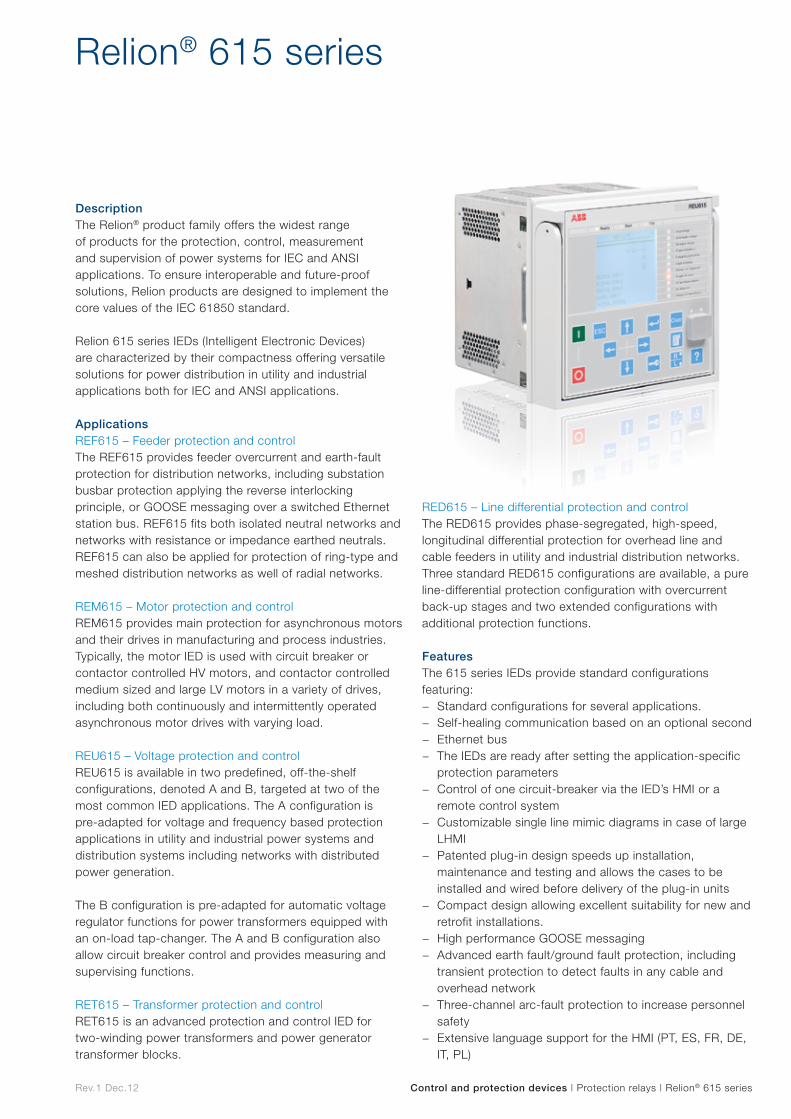
Rev.1 Dec.12 Control and protection devices | Protection relays | Relion® 615 series
DescriptionThe Relion® product family offers the widest range of products for the protection, control, measurement and supervision of power systems for IEC and ANSI applications. To ensure interoperable and future-proof solutions, Relion products are designed to implement the core values of the IEC 61850 standard.
Relion 615 series IEDs (Intelligent Electronic Devices) are characterized by their compactness offering versatile solutions for power distribution in utility and industrial applications both for IEC and ANSI applications.
ApplicationsREF615 – Feeder protection and control The REF615 provides feeder overcurrent and earth-fault protection for distribution networks, including substation busbar protection applying the reverse interlocking principle, or GOOSE messaging over a switched Ethernet station bus. REF615 fits both isolated neutral networks and networks with resistance or impedance earthed neutrals. REF615 can also be applied for protection of ring-type and meshed distribution networks as well of radial networks.
REM615 – Motor protection and control REM615 provides main protection for asynchronous motors and their drives in manufacturing and process industries. Typically, the motor IED is used with circuit breaker or contactor controlled HV motors, and contactor controlled medium sized and large LV motors in a variety of drives, including both continuously and intermittently operated asynchronous motor drives with varying load.
REU615 – Voltage protection and control REU615 is available in two predefined, off-the-shelf configurations, denoted A and B, targeted at two of the most common IED applications. The A configuration is pre-adapted for voltage and frequency based protection applications in utility and industrial power systems and distribution systems including networks with distributed power generation.
The B configuration is pre-adapted for automatic voltage regulator functions for power transformers equipped with an on-load tap-changer. The A and B configuration also allow circuit breaker control and provides measuring and supervising functions.
RET615 – Transformer protection and control RET615 is an advanced protection and control IED for two-winding power transformers and power generator transformer blocks.
RED615 – Line differential protection and control The RED615 provides phase-segregated, high-speed, longitudinal differential protection for overhead line and cable feeders in utility and industrial distribution networks. Three standard RED615 configurations are available, a pure line-differential protection configuration with overcurrent back-up stages and two extended configurations with additional protection functions.
FeaturesThe 615 series IEDs provide standard configurations featuring:
− Standard configurations for several applications. − Self-healing communication based on an optional second − Ethernet bus − The IEDs are ready after setting the application-specific
protection parameters − Control of one circuit-breaker via the IED’s HMI or a
remote control system − Customizable single line mimic diagrams in case of large
LHMI − Patented plug-in design speeds up installation,
maintenance and testing and allows the cases to be installed and wired before delivery of the plug-in units
− Compact design allowing excellent suitability for new and retrofit installations.
− High performance GOOSE messaging − Advanced earth fault/ground fault protection, including
transient protection to detect faults in any cable and overhead network
− Three-channel arc-fault protection to increase personnel safety
− Extensive language support for the HMI (PT, ES, FR, DE, IT, PL)
Relion® 615 series
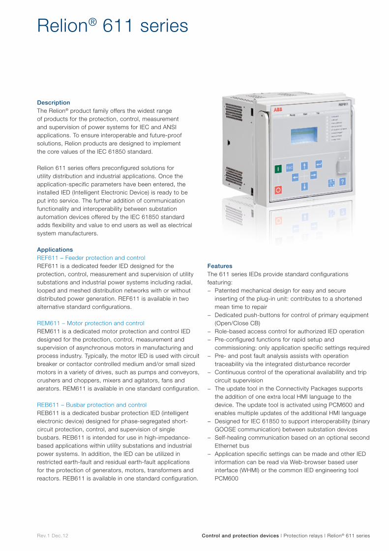
Rev.1 Dec.12 Control and protection devices | Protection relays | Relion® 611 series
Relion® 611 series
DescriptionThe Relion® product family offers the widest range of products for the protection, control, measurement and supervision of power systems for IEC and ANSI applications. To ensure interoperable and future-proof solutions, Relion products are designed to implement the core values of the IEC 61850 standard.
Relion 611 series offers preconfigured solutions for utility distribution and industrial applications. Once the application-specific parameters have been entered, the installed IED (Intelligent Electronic Device) is ready to be put into service. The further addition of communication functionality and interoperability between substation automation devices offered by the IEC 61850 standard adds flexibility and value to end users as well as electrical system manufacturers.
ApplicationsREF611 – Feeder protection and control REF611 is a dedicated feeder IED designed for the protection, control, measurement and supervision of utility substations and industrial power systems including radial, looped and meshed distribution networks with or without distributed power generation. REF611 is available in two alternative standard configurations.
REM611 – Motor protection and control REM611 is a dedicated motor protection and control IED designed for the protection, control, measurement and supervision of asynchronous motors in manufacturing and process industry. Typically, the motor IED is used with circuit breaker or contactor controlled medium and/or small sized motors in a variety of drives, such as pumps and conveyors, crushers and choppers, mixers and agitators, fans and aerators. REM611 is available in one standard configuration.
REB611 – Busbar protection and control REB611 is a dedicated busbar protection IED (intelligent electronic device) designed for phase-segregated short-circuit protection, control, and supervision of single busbars. REB611 is intended for use in high-impedance-based applications within utility substations and industrial power systems. In addition, the IED can be utilized in restricted earth-fault and residual earth-fault applications for the protection of generators, motors, transformers and reactors. REB611 is available in one standard configuration.
FeaturesThe 611 series IEDs provide standard configurations featuring:
− Patented mechanical design for easy and secure inserting of the plug-in unit: contributes to a shortened mean time to repair
− Dedicated push-buttons for control of primary equipment (Open/Close CB)
− Role-based access control for authorized IED operation − Pre-configured functions for rapid setup and
commissioning: only application specific settings required − Pre- and post fault analysis assists with operation
traceability via the integrated disturbance recorder − Continuous control of the operational availability and trip
circuit supervision − The update tool in the Connectivity Packages supports
the addition of one extra local HMI language to the device. The update tool is activated using PCM600 and enables multiple updates of the additional HMI language
− Designed for IEC 61850 to support interoperability (binary GOOSE communication) between substation devices
− Self-healing communication based on an optional second Ethernet bus
− Application specific settings can be made and other IED information can be read via Web-browser based user interface (WHMI) or the common IED engineering tool PCM600
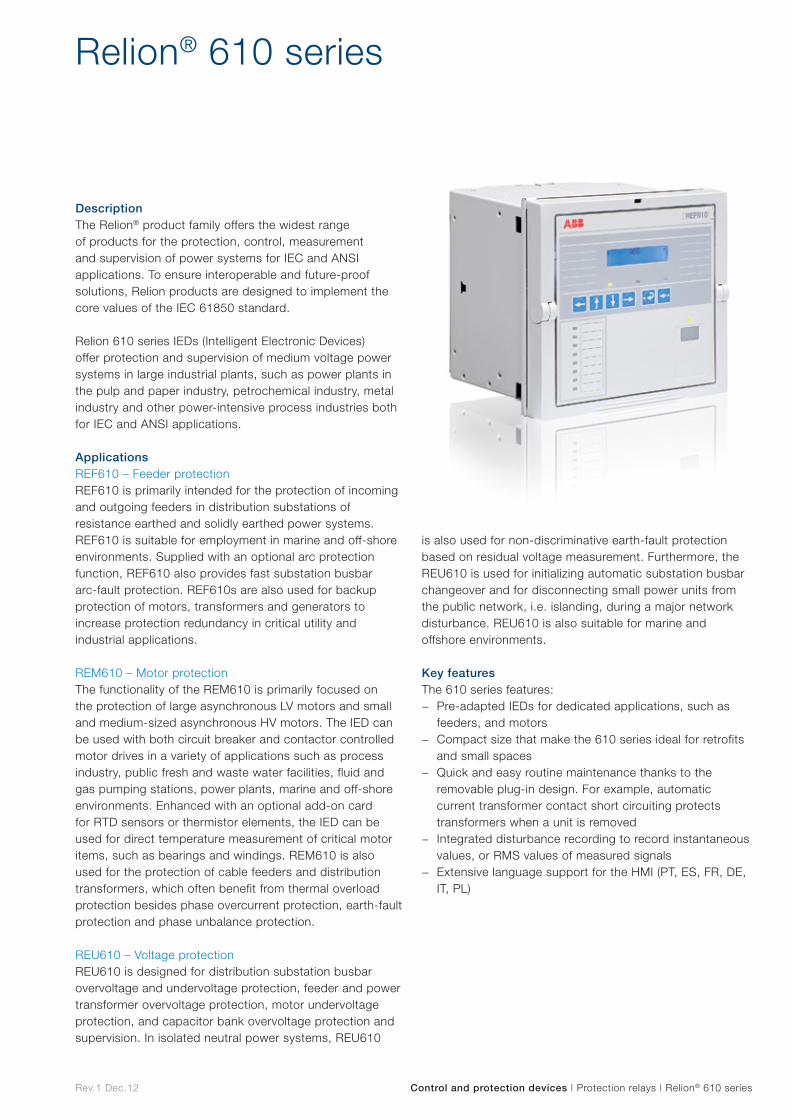
Rev.1 Dec.12
Relion® 610 series
Control and protection devices | Protection relays | Relion® 610 series
DescriptionThe Relion® product family offers the widest range of products for the protection, control, measurement and supervision of power systems for IEC and ANSI applications. To ensure interoperable and future-proof solutions, Relion products are designed to implement the core values of the IEC 61850 standard.
Relion 610 series IEDs (Intelligent Electronic Devices) offer protection and supervision of medium voltage power systems in large industrial plants, such as power plants in the pulp and paper industry, petrochemical industry, metal industry and other power-intensive process industries both for IEC and ANSI applications.
ApplicationsREF610 – Feeder protection REF610 is primarily intended for the protection of incoming and outgoing feeders in distribution substations of resistance earthed and solidly earthed power systems. REF610 is suitable for employment in marine and off-shore environments. Supplied with an optional arc protection function, REF610 also provides fast substation busbar arc-fault protection. REF610s are also used for backup protection of motors, transformers and generators to increase protection redundancy in critical utility and industrial applications.
REM610 – Motor protection The functionality of the REM610 is primarily focused on the protection of large asynchronous LV motors and small and medium-sized asynchronous HV motors. The IED can be used with both circuit breaker and contactor controlled motor drives in a variety of applications such as process industry, public fresh and waste water facilities, fluid and gas pumping stations, power plants, marine and off-shore environments. Enhanced with an optional add-on card for RTD sensors or thermistor elements, the IED can be used for direct temperature measurement of critical motor items, such as bearings and windings. REM610 is also used for the protection of cable feeders and distribution transformers, which often benefit from thermal overload protection besides phase overcurrent protection, earth-fault protection and phase unbalance protection.
REU610 – Voltage protection REU610 is designed for distribution substation busbar overvoltage and undervoltage protection, feeder and power transformer overvoltage protection, motor undervoltage protection, and capacitor bank overvoltage protection and supervision. In isolated neutral power systems, REU610
is also used for non-discriminative earth-fault protection based on residual voltage measurement. Furthermore, the REU610 is used for initializing automatic substation busbar changeover and for disconnecting small power units from the public network, i.e. islanding, during a major network disturbance. REU610 is also suitable for marine and offshore environments.
Key featuresThe 610 series features:
− Pre-adapted IEDs for dedicated applications, such as feeders, and motors
− Compact size that make the 610 series ideal for retrofits and small spaces
− Quick and easy routine maintenance thanks to the removable plug-in design. For example, automatic current transformer contact short circuiting protects transformers when a unit is removed
− Integrated disturbance recording to record instantaneous values, or RMS values of measured signals
− Extensive language support for the HMI (PT, ES, FR, DE, IT, PL)
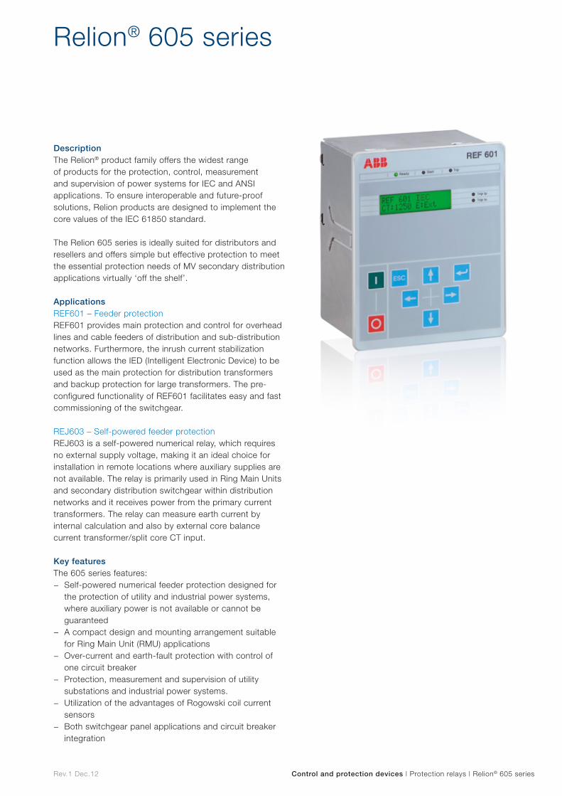
Rev.1 Dec.12 Control and protection devices | Protection relays | Relion® 605 series
Relion® 605 series
DescriptionThe Relion® product family offers the widest range of products for the protection, control, measurement and supervision of power systems for IEC and ANSI applications. To ensure interoperable and future-proof solutions, Relion products are designed to implement the core values of the IEC 61850 standard.
The Relion 605 series is ideally suited for distributors and resellers and offers simple but effective protection to meet the essential protection needs of MV secondary distribution applications virtually ‘off the shelf’.
ApplicationsREF601 – Feeder protection REF601 provides main protection and control for overhead lines and cable feeders of distribution and sub-distribution networks. Furthermore, the inrush current stabilization function allows the IED (Intelligent Electronic Device) to be used as the main protection for distribution transformers and backup protection for large transformers. The pre-configured functionality of REF601 facilitates easy and fast commissioning of the switchgear.
REJ603 – Self-powered feeder protection REJ603 is a self-powered numerical relay, which requires no external supply voltage, making it an ideal choice for installation in remote locations where auxiliary supplies are not available. The relay is primarily used in Ring Main Units and secondary distribution switchgear within distribution networks and it receives power from the primary current transformers. The relay can measure earth current by internal calculation and also by external core balance current transformer/split core CT input.
Key featuresThe 605 series features:
− Self-powered numerical feeder protection designed for the protection of utility and industrial power systems, where auxiliary power is not available or cannot be guaranteed
− A compact design and mounting arrangement suitable for Ring Main Unit (RMU) applications
− Over-current and earth-fault protection with control of one circuit breaker
− Protection, measurement and supervision of utility substations and industrial power systems.
− Utilization of the advantages of Rogowski coil current sensors
− Both switchgear panel applications and circuit breaker integration
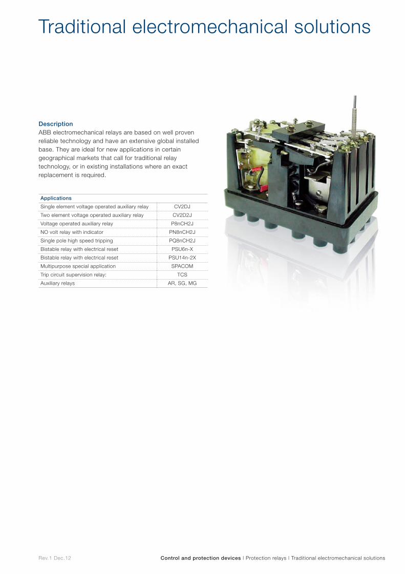
Rev.1 Dec.12 Control and protection devices | Protection relays | Traditional electromechanical solutions
Traditional electromechanical solutions
DescriptionABB electromechanical relays are based on well proven reliable technology and have an extensive global installed base. They are ideal for new applications in certain geographical markets that call for traditional relay technology, or in existing installations where an exact replacement is required.
Applications
Single element voltage operated auxiliary relay CV2DJ
Two element voltage operated auxiliary relay CV2D2J
Voltage operated auxiliary relay P8nCH2J
NO volt relay with indicator PN8nCH2J
Single pole high speed tripping PQ8nCH2J
Bistable relay with electrical reset PSU6n-X
Bistable relay with electrical reset PSU14n-2X
Multipurpose special application SPACOM
Trip circuit supervision relay: TCS
Auxiliary relays AR, SG, MG
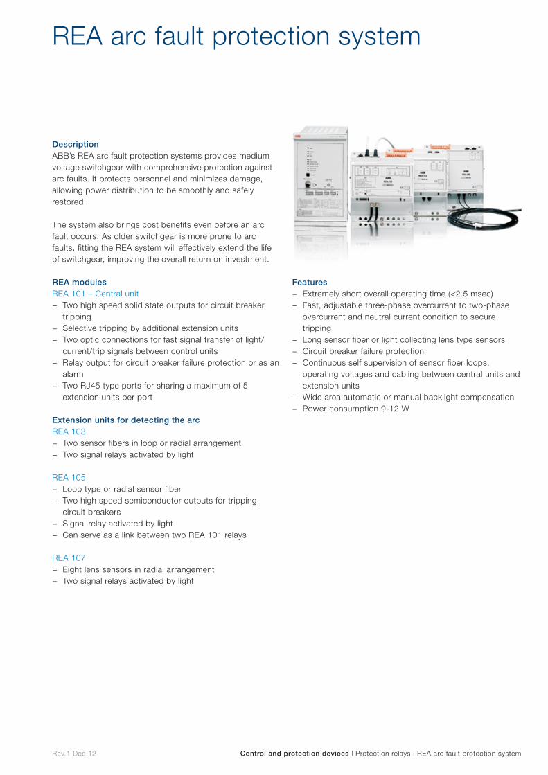
Rev.1 Dec.12 Control and protection devices | Protection relays | REA arc fault protection system
REA arc fault protection system
DescriptionABB’s REA arc fault protection systems provides medium voltage switchgear with comprehensive protection against arc faults. It protects personnel and minimizes damage, allowing power distribution to be smoothly and safely restored.
The system also brings cost benefits even before an arc fault occurs. As older switchgear is more prone to arc faults, fitting the REA system will effectively extend the life of switchgear, improving the overall return on investment.
REA modulesREA 101 – Central unit
− Two high speed solid state outputs for circuit breaker tripping
− Selective tripping by additional extension units − Two optic connections for fast signal transfer of light/
current/trip signals between control units − Relay output for circuit breaker failure protection or as an
alarm − Two RJ45 type ports for sharing a maximum of 5
extension units per port
Extension units for detecting the arcREA 103
− Two sensor fibers in loop or radial arrangement − Two signal relays activated by light
REA 105 − Loop type or radial sensor fiber − Two high speed semiconductor outputs for tripping
circuit breakers − Signal relay activated by light − Can serve as a link between two REA 101 relays
REA 107 − Eight lens sensors in radial arrangement − Two signal relays activated by light
Features − Extremely short overall operating time (<2.5 msec) − Fast, adjustable three-phase overcurrent to two-phase
overcurrent and neutral current condition to secure tripping
− Long sensor fiber or light collecting lens type sensors − Circuit breaker failure protection − Continuous self supervision of sensor fiber loops,
operating voltages and cabling between central units and extension units
− Wide area automatic or manual backlight compensation − Power consumption 9-12 W

Control devices Co
ntrol
devices
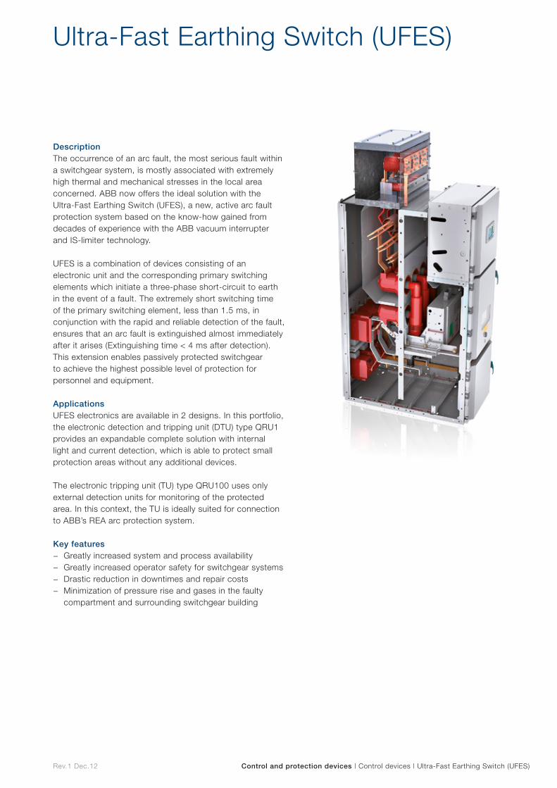
Rev.1 Dec.12 Control and protection devices | Control devices | Ultra-Fast Earthing Switch (UFES)
Ultra-Fast Earthing Switch (UFES)
DescriptionThe occurrence of an arc fault, the most serious fault within a switchgear system, is mostly associated with extremely high thermal and mechanical stresses in the local area concerned. ABB now offers the ideal solution with the Ultra-Fast Earthing Switch (UFES), a new, active arc fault protection system based on the know-how gained from decades of experience with the ABB vacuum interrupter and IS-limiter technology.
UFES is a combination of devices consisting of an electronic unit and the corresponding primary switching elements which initiate a three-phase short-circuit to earth in the event of a fault. The extremely short switching time of the primary switching element, less than 1.5 ms, in conjunction with the rapid and reliable detection of the fault, ensures that an arc fault is extinguished almost immediately after it arises (Extinguishing time < 4 ms after detection). This extension enables passively protected switchgear to achieve the highest possible level of protection for personnel and equipment.
ApplicationsUFES electronics are available in 2 designs. In this portfolio, the electronic detection and tripping unit (DTU) type QRU1 provides an expandable complete solution with internal light and current detection, which is able to protect small protection areas without any additional devices.
The electronic tripping unit (TU) type QRU100 uses only external detection units for monitoring of the protected area. In this context, the TU is ideally suited for connection to ABB’s REA arc protection system.
Key features − Greatly increased system and process availability − Greatly increased operator safety for switchgear systems − Drastic reduction in downtimes and repair costs − Minimization of pressure rise and gases in the faulty
compartment and surrounding switchgear building
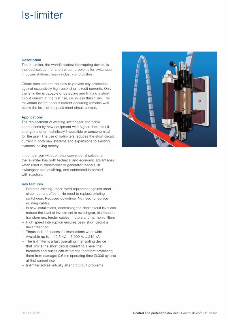
Rev.1 Dec.12 Control and protection devices | Control devices | Is-limiter
Is-limiter
DescriptionThe Is-Limiter, the world’s fastest interrupting device, is the ideal solution for short circuit problems for switchgear in power stations, heavy industry and utilities.
Circuit breakers are too slow to provide any protection against excessively high peak short circuit currents. Only the Is-limiter is capable of detecting and limiting a short circuit current at the first rise, i.e. in less than 1 ms. The maximum instantaneous current occurring remains well below the level of the peak short circuit current.
ApplicationsThe replacement of existing switchgear and cable connections by new equipment with higher short circuit strength is often technically impossible or uneconomical for the user. The use of Is-limiters reduces the short circuit current in both new systems and expansions to existing systems, saving money.
In comparison with complex conventional solutions, the Is-limiter has both technical and economic advantages when used in transformer or generator feeders, in switchgear sectionalizing, and connected in parallel with reactors.
Key features − Protects existing under-rated equipment against short
circuit current effects. No need to replace existing switchgear. Reduced downtime. No need to replace existing cables
− In new installations, decreasing the short circuit level can reduce the level of investment in switchgear, distribution transformers, feeder cables, motors and harmonic filters
− High speed interruption ensures peak short circuit is never reached
− Thousands of successful installations worldwide − Available up to ...40.5 kV, ...5,000 A, ...210 kA − The Is-limiter is a fast operating interrupting device
that limits the short circuit current to a level that breakers and buses can withstand therefore protecting them from damage: 0.6 ms operating time (0.036 cycles) at first current rise
− Is-limiter solves virtually all short circuit problems

Accessories
Accesso
ries
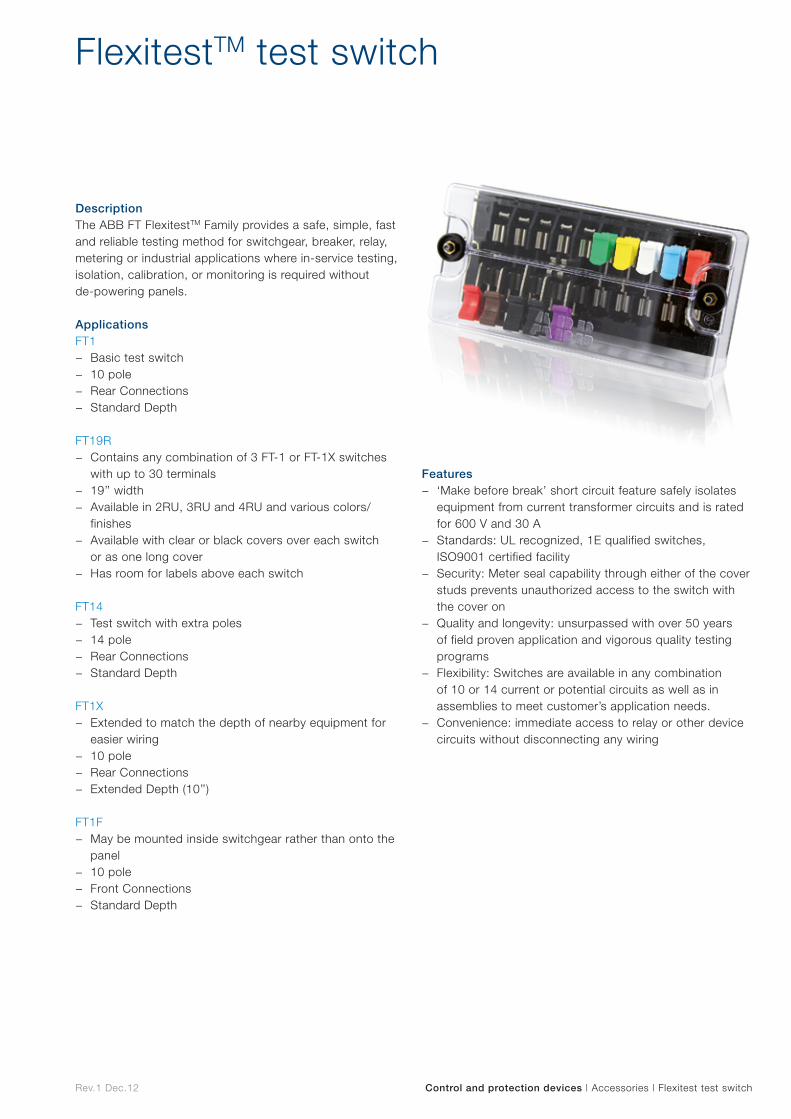
Rev.1 Dec.12 Control and protection devices | Accessories | Flexitest test switch
FlexitestTM test switch
DescriptionThe ABB FT FlexitestTM Family provides a safe, simple, fast and reliable testing method for switchgear, breaker, relay, metering or industrial applications where in-service testing, isolation, calibration, or monitoring is required without de-powering panels.
ApplicationsFT1
− Basic test switch − 10 pole − Rear Connections − Standard Depth
FT19R
− Contains any combination of 3 FT-1 or FT-1X switches with up to 30 terminals
− 19’’ width − Available in 2RU, 3RU and 4RU and various colors/
finishes − Available with clear or black covers over each switch
or as one long cover − Has room for labels above each switch
FT14 − Test switch with extra poles − 14 pole − Rear Connections − Standard Depth
FT1X − Extended to match the depth of nearby equipment for
easier wiring − 10 pole − Rear Connections − Extended Depth (10’’)
FT1F − May be mounted inside switchgear rather than onto the
panel − 10 pole − Front Connections − Standard Depth
Features − ‘Make before break’ short circuit feature safely isolates
equipment from current transformer circuits and is rated for 600 V and 30 A
− Standards: UL recognized, 1E qualified switches, ISO9001 certified facility
− Security: Meter seal capability through either of the cover studs prevents unauthorized access to the switch with the cover on
− Quality and longevity: unsurpassed with over 50 years of field proven application and vigorous quality testing programs
− Flexibility: Switches are available in any combination of 10 or 14 current or potential circuits as well as in assemblies to meet customer’s application needs.
− Convenience: immediate access to relay or other device circuits without disconnecting any wiring

Fuses/Cutouts
Fuses
/Cuto
uts
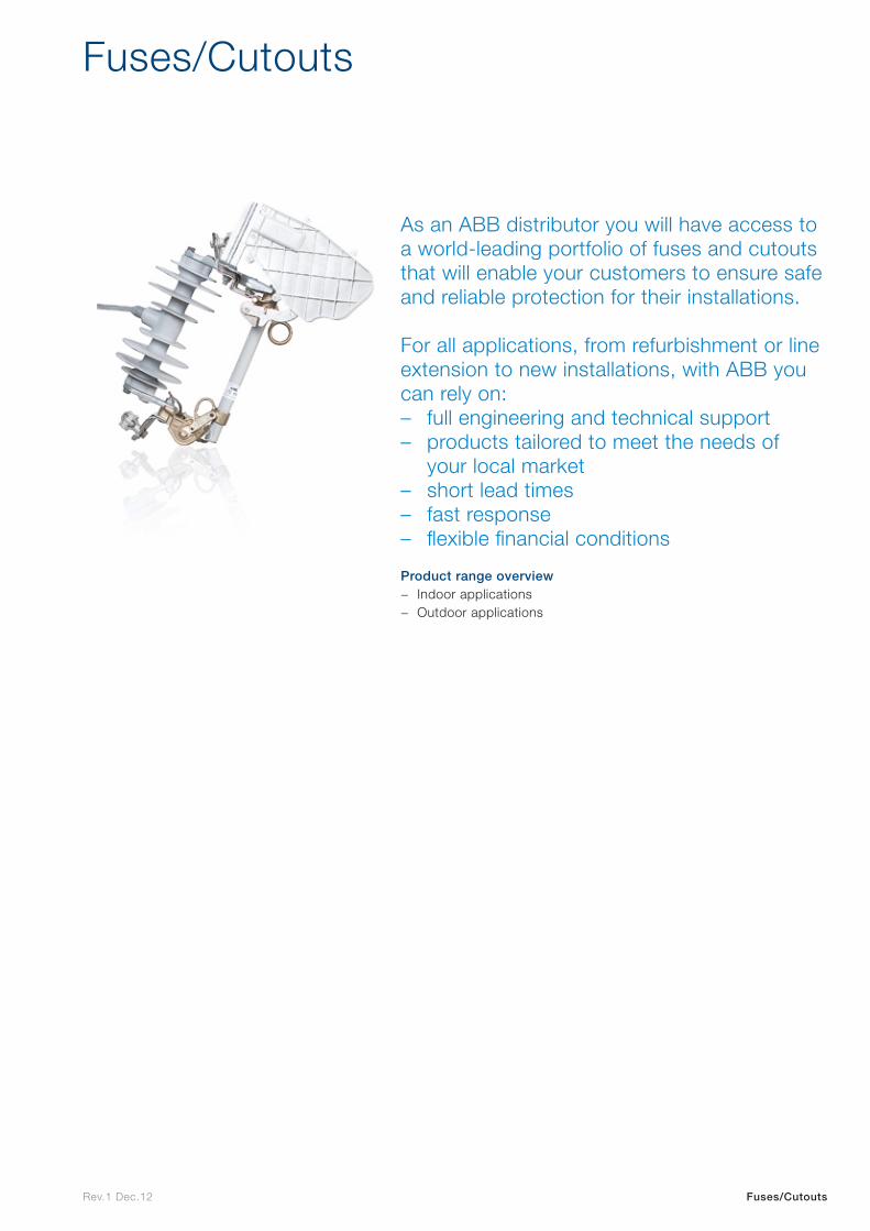
Rev.1 Dec.12 Fuses/Cutouts
Fuses/Cutouts
As an ABB distributor you will have access to a world-leading portfolio of fuses and cutouts that will enable your customers to ensure safe and reliable protection for their installations.
For all applications, from refurbishment or line extension to new installations, with ABB you can rely on: – full engineering and technical support – products tailored to meet the needs of
your local market – short lead times – fast response – flexible financial conditions
Product range overview − Indoor applications − Outdoor applications

Indoor applications
Indo
or
app
lications
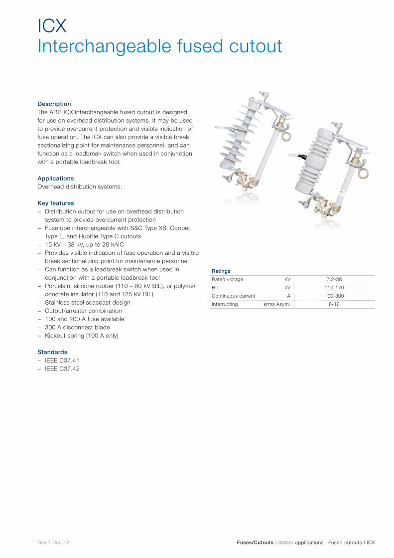
Rev.1 Dec.12 Fuses/Cutouts | Indoor applications | Fused cutouts | ICX
DescriptionThe ABB ICX interchangeable fused cutout is designed for use on overhead distribution systems. It may be used to provide overcurrent protection and visible indication of fuse operation. The ICX can also provide a visible break sectionalizing point for maintenance personnel, and can function as a loadbreak switch when used in conjunction with a portable loadbreak tool.
ApplicationsOverhead distribution systems.
Key features − Distribution cutout for use on overhead distribution
system to provide overcurrent protection − Fusetube interchangeable with S&C Type XS, Cooper
Type L, and Hubble Type C cutouts − 15 kV – 38 kV, up to 20 kAIC − Provides visible indication of fuse operation and a visible
break sectionalizing point for maintenance personnel − Can function as a loadbreak switch when used in
conjunction with a portable loadbreak tool − Porcelain, silicone rubber (110 – 80 kV BIL), or polymer
concrete insulator (110 and 125 kV BIL) − Stainless steel seacoast design − Cutout/arrester combination − 100 and 200 A fuse available − 300 A disconnect blade − Kickout spring (100 A only)
Standards − IEEE C37.41 − IEEE C37.42
ICXInterchangeable fused cutout
Ratings
Rated voltage kV 7.2-38
BIL kV 110-170
Continuous current A 100-300
Interrupting krms Asym. 8-16
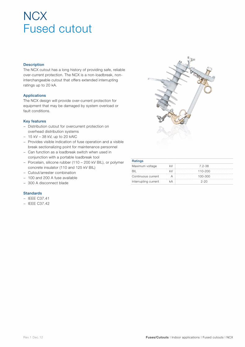
Rev.1 Dec.12
DescriptionThe NCX cutout has a long history of providing safe, reliable over-current protection. The NCX is a non-loadbreak, non-interchangeable cutout that offers extended interrupting ratings up to 20 kA.
ApplicationsThe NCX design will provide over-current protection for equipment that may be damaged by system overload or fault conditions.
Key features − Distribution cutout for overcurrent protection on
overhead distribution systems − 15 kV – 38 kV, up to 20 kAIC − Provides visible indication of fuse operation and a visible
break sectionalizing point for maintenance personnel − Can function as a loadbreak switch when used in
conjunction with a portable loadbreak tool − Porcelain, silicone rubber (110 – 200 kV BIL), or polymer
concrete insulator (110 and 125 kV BIL) − Cutout/arrester combination − 100 and 200 A fuse available − 300 A disconnect blade
Standards − IEEE C37.41 − IEEE C37.42
NCXFused cutout
Fuses/Cutouts | Indoor applications | Fused cutouts | NCX
Ratings
Maximum voltage kV 7.2-38
BIL kV 110-200
Continuous current A 100-300
Interrupting current kA 2-20
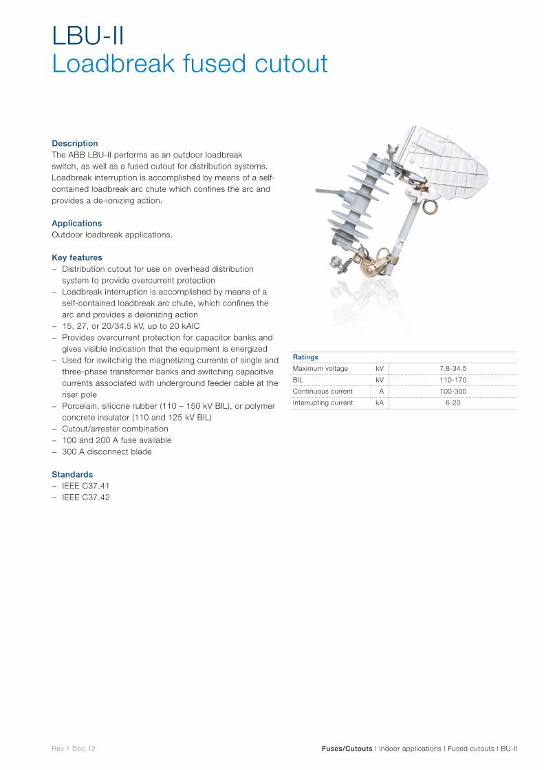
Rev.1 Dec.12
DescriptionThe ABB LBU-II performs as an outdoor loadbreak switch, as well as a fused cutout for distribution systems. Loadbreak interruption is accomplished by means of a self-contained loadbreak arc chute which confines the arc and provides a de-ionizing action.
ApplicationsOutdoor loadbreak applications.
Key features − Distribution cutout for use on overhead distribution
system to provide overcurrent protection − Loadbreak interruption is accomplished by means of a
self-contained loadbreak arc chute, which confines the arc and provides a deionizing action
− 15, 27, or 20/34.5 kV, up to 20 kAIC − Provides overcurrent protection for capacitor banks and
gives visible indication that the equipment is energized − Used for switching the magnetizing currents of single and
three-phase transformer banks and switching capacitive currents associated with underground feeder cable at the riser pole
− Porcelain, silicone rubber (110 – 150 kV BIL), or polymer concrete insulator (110 and 125 kV BIL)
− Cutout/arrester combination − 100 and 200 A fuse available − 300 A disconnect blade
Standards − IEEE C37.41 − IEEE C37.42
LBU-II Loadbreak fused cutout
Fuses/Cutouts | Indoor applications | Fused cutouts | BU-II
Ratings
Maximum voltage kV 7.8-34.5
BIL kV 110-170
Continuous current A 100-300
Interrupting current kA 6-20
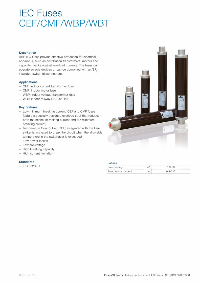
Rev.1 Dec.12 Fuses/Cutouts | Indoor applications | IEC Fuses | CEF/CMF/WBP/WBT
DescriptionABB IEC fuses provide effective protection for electrical apparatus, such as distribution transformers, motors and capacitor banks against overload currents. The fuses can operate as sole devices or can be combined with air/SF6-insulated switch disconnectors.
Applications − CEF: indoor current transformer fuse − CMF: indoor motor fuse − WBP: indoor voltage transformer fuse − WBT: indoor railway DC fuse-link
Key features − Low minimum breaking current (CEF and CMF fuses
feature a specially designed overload spot that reduces both the minimum melting current and the minimum breaking current)
− Temperature Control Unit (TCU) integrated with the fuse striker is activated to break the circuit when the allowable temperature in the switchgear is exceeded
− Low power losses − Low arc-voltage − High breaking capacity − High current limitation
Standards − IEC 60282-1
IEC FusesCEF/CMF/WBP/WBT
Ratings
Rated voltage kV 1.9-36
Rated normal current A 0.4-315

Outdoor applications Outd
oo
r ap
plicatio
ns
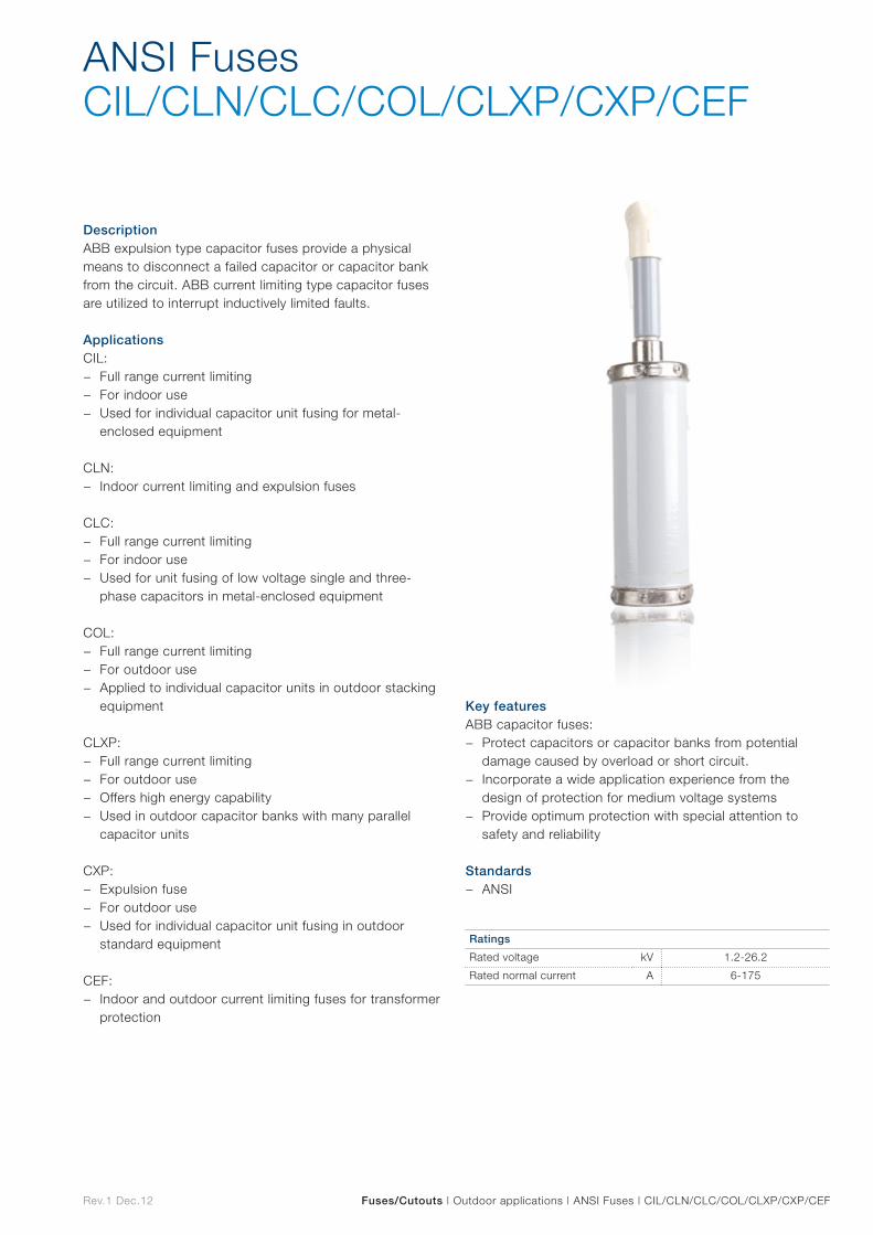
Rev.1 Dec.12 Fuses/Cutouts | Outdoor applications | ANSI Fuses | CIL/CLN/CLC/COL/CLXP/CXP/CEF
DescriptionABB expulsion type capacitor fuses provide a physical means to disconnect a failed capacitor or capacitor bank from the circuit. ABB current limiting type capacitor fuses are utilized to interrupt inductively limited faults.
ApplicationsCIL:
− Full range current limiting − For indoor use − Used for individual capacitor unit fusing for metal-
enclosed equipment
CLN: − Indoor current limiting and expulsion fuses
CLC: − Full range current limiting − For indoor use − Used for unit fusing of low voltage single and three-
phase capacitors in metal-enclosed equipment
COL: − Full range current limiting − For outdoor use − Applied to individual capacitor units in outdoor stacking
equipment
CLXP: − Full range current limiting − For outdoor use − Offers high energy capability − Used in outdoor capacitor banks with many parallel
capacitor units
CXP: − Expulsion fuse − For outdoor use − Used for individual capacitor unit fusing in outdoor
standard equipment
CEF: − Indoor and outdoor current limiting fuses for transformer
protection
Key featuresABB capacitor fuses:
− Protect capacitors or capacitor banks from potential damage caused by overload or short circuit.
− Incorporate a wide application experience from the design of protection for medium voltage systems
− Provide optimum protection with special attention to safety and reliability
Standards − ANSI
ANSI FusesCIL/CLN/CLC/COL/CLXP/CXP/CEF
Ratings
Rated voltage kV 1.2-26.2
Rated normal current A 6-175

Instrument transformers
Instrument
transform
ers
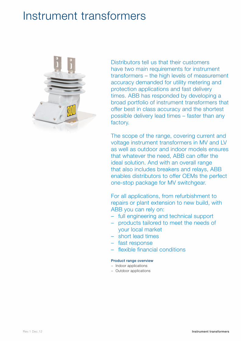
Rev.1 Dec.12 Instrument transformers
Instrument transformers
Distributors tell us that their customers have two main requirements for instrument transformers – the high levels of measurement accuracy demanded for utility metering and protection applications and fast delivery times. ABB has responded by developing a broad portfolio of instrument transformers that offer best in class accuracy and the shortest possible delivery lead times – faster than any factory.
The scope of the range, covering current and voltage instrument transformers in MV and LV as well as outdoor and indoor models ensures that whatever the need, ABB can offer the ideal solution. And with an overall range that also includes breakers and relays, ABB enables distributors to offer OEMs the perfect one-stop package for MV switchgear.
For all applications, from refurbishment to repairs or plant extension to new build, with ABB you can rely on: – full engineering and technical support – products tailored to meet the needs of
your local market – short lead times – fast response – flexible financial conditions
Product range overview
− Indoor applications − Outdoor applications

Indoor applications
Indo
or
app
lications
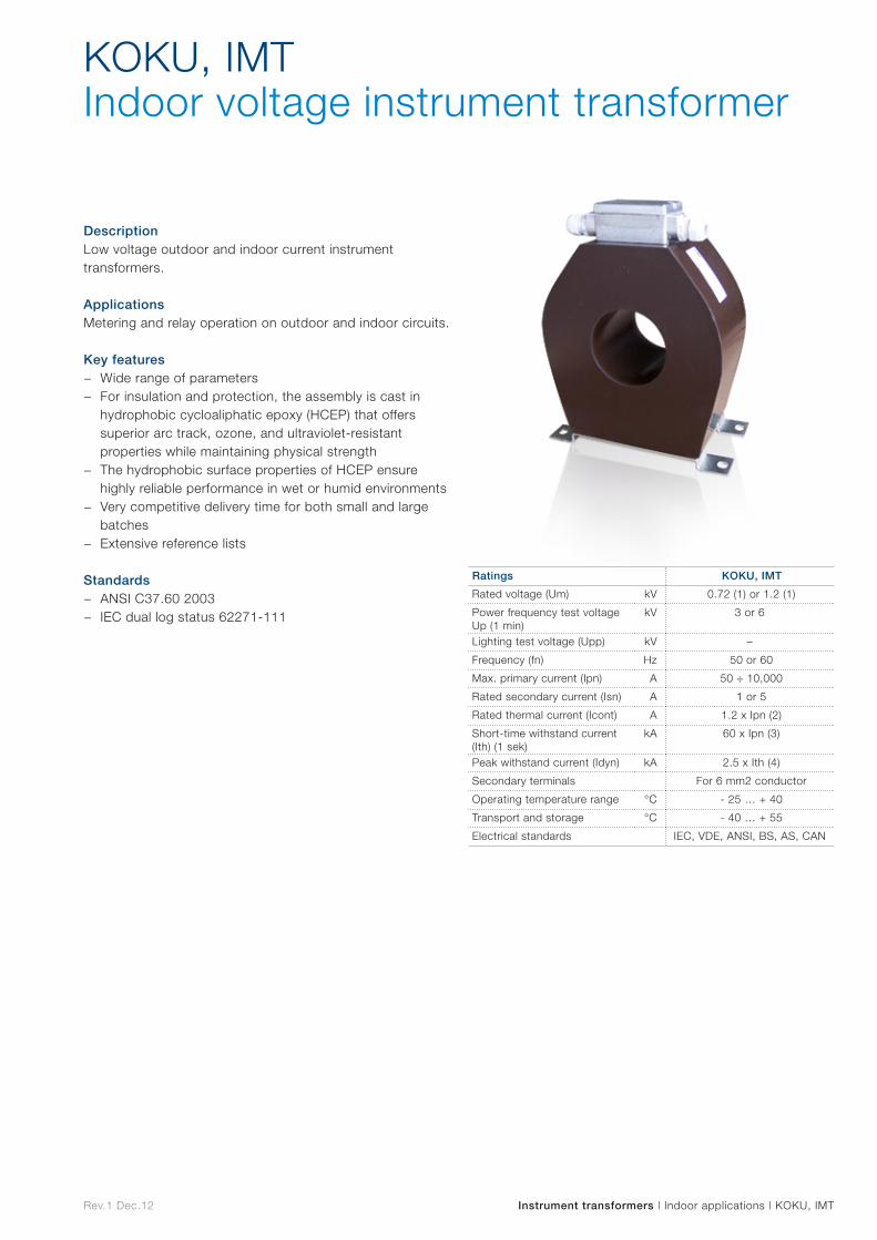
Rev.1 Dec.12 Instrument transformers | Indoor applications | KOKU, IMT
DescriptionLow voltage outdoor and indoor current instrument transformers.
ApplicationsMetering and relay operation on outdoor and indoor circuits.
Key features − Wide range of parameters − For insulation and protection, the assembly is cast in
hydrophobic cycloaliphatic epoxy (HCEP) that offers superior arc track, ozone, and ultraviolet-resistant properties while maintaining physical strength
− The hydrophobic surface properties of HCEP ensure highly reliable performance in wet or humid environments
− Very competitive delivery time for both small and large batches
− Extensive reference lists
Standards − ANSI C37.60 2003 − IEC dual log status 62271-111
KOKU, IMT Indoor voltage instrument transformer
Ratings KOKU, IMT
Rated voltage (Um) kV 0.72 (1) or 1.2 (1)
Power frequency test voltage Up (1 min)
kV 3 or 6
Lighting test voltage (Upp) kV –
Frequency (fn) Hz 50 or 60
Max. primary current (Ipn) A 50 ÷ 10,000
Rated secondary current (Isn) A 1 or 5
Rated thermal current (Icont) A 1.2 x Ipn (2)
Short-time withstand current (Ith) (1 sek)
kA 60 x Ipn (3)
Peak withstand current (Idyn) kA 2.5 x Ith (4)
Secondary terminals For 6 mm2 conductor
Operating temperature range °C - 25 … + 40
Transport and storage °C - 40 … + 55
Electrical standards IEC, VDE, ANSI, BS, AS, CAN

Outdoor applications Outd
oo
r ap
plicatio
ns
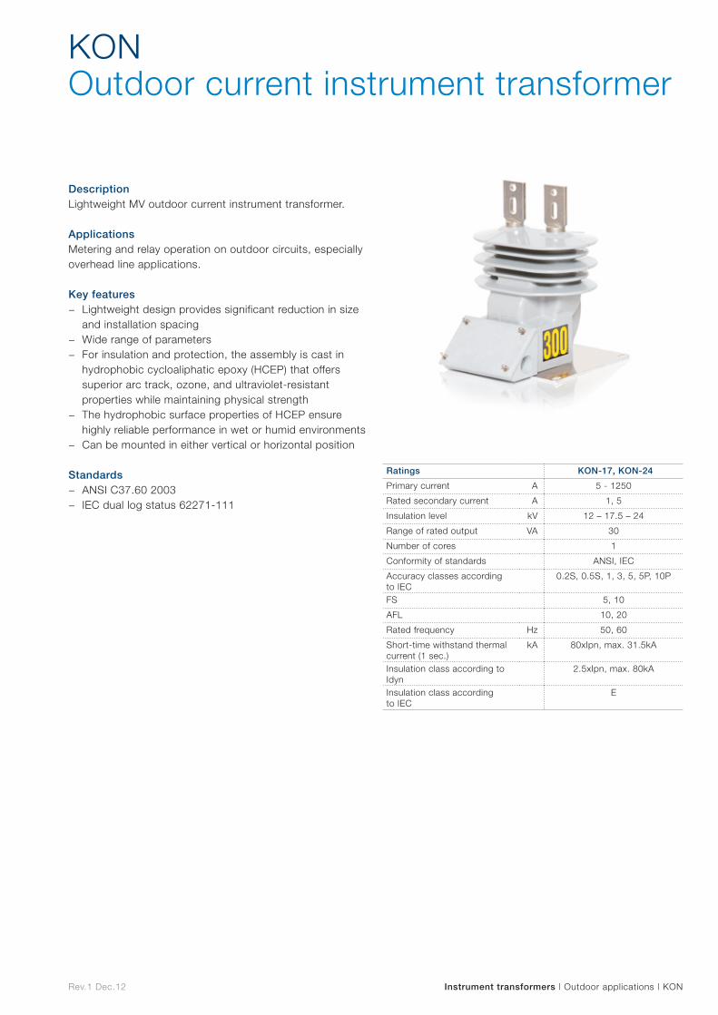
Rev.1 Dec.12 Instrument transformers | Outdoor applications | KON
DescriptionLightweight MV outdoor current instrument transformer.
ApplicationsMetering and relay operation on outdoor circuits, especially overhead line applications.
Key features − Lightweight design provides significant reduction in size
and installation spacing − Wide range of parameters − For insulation and protection, the assembly is cast in
hydrophobic cycloaliphatic epoxy (HCEP) that offers superior arc track, ozone, and ultraviolet-resistant properties while maintaining physical strength
− The hydrophobic surface properties of HCEP ensure highly reliable performance in wet or humid environments
− Can be mounted in either vertical or horizontal position
Standards − ANSI C37.60 2003 − IEC dual log status 62271-111
KONOutdoor current instrument transformer
Ratings KON-17, KON-24
Primary current A 5 - 1250
Rated secondary current A 1, 5
Insulation level kV 12 – 17.5 – 24
Range of rated output VA 30
Number of cores 1
Conformity of standards ANSI, IEC
Accuracy classes according to IEC
0.2S, 0.5S, 1, 3, 5, 5P, 10P
FS 5, 10
AFL 10, 20
Rated frequency Hz 50, 60
Short-time withstand thermal current (1 sec.)
kA 80xIpn, max. 31.5kA
Insulation class according to Idyn
2.5xIpn, max. 80kA
Insulation class according to IEC
E
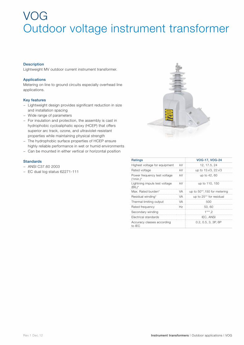
Rev.1 Dec.12 Instrument transformers | Outdoor applications | VOG
DescriptionLightweight MV outdoor current instrument transformer.
ApplicationsMetering on line to ground circuits especially overhead line applications.
Key features − Lightweight design provides significant reduction in size
and installation spacing − Wide range of parameters − For insulation and protection, the assembly is cast in
hydrophobic cycloaliphatic epoxy (HCEP) that offers superior arc track, ozone, and ultraviolet-resistant properties while maintaining physical strength
− The hydrophobic surface properties of HCEP ensure highly reliable performance in wet or humid environments
− Can be mounted in either vertical or horizontal position
Standards − ANSI C37.60 2003 − EC dual log status 62271-111
VOGOutdoor voltage instrument transformer
Ratings VOG-17, VOG-24
Highest voltage for equipment kV 12, 17.5, 24
Rated voltage kV up to 15:√3, 22:√3
Power frequency test voltage (1min.)*
kV up to 42, 60
Lightning impuls test voltage (BIL)*
kV up to 110, 150
Max. Rated burden* VA up to 50**,150 for metering
Residual winding* VA up to 25** for residual
Thermal limiting output VA 500
Rated frequency Hz 50, 60
Secondary winding 1***,2
Electrical standards IEC, ANSI
Accuracy classes according to IEC
0.2, 0.5, 3, 3P, 6P
Rev.1 Dec.12 Instrument transformers | Outdoor applications | VOL
DescriptionLightweight MV outdoor current instrument transformer.
ApplicationsMetering on line to ground circuits especially overhead line applications.
Key features − Lightweight design provides significant reduction in size
and installation spacing − Wide range of parameters − For insulation and protection, the assembly is cast in
hydrophobic cycloaliphatic epoxy (HCEP) that offers superior arc track, ozone, and ultraviolet-resistant properties while maintaining physical strength
− The hydrophobic surface properties of HCEP ensure highly reliable performance in wet or humid environments
− Can be mounted in either vertical or horizontal position
Standards − ANSI C37.60 2003 − EC dual log status 62271-111
VOLOutdoor voltage instrument transformer
Ratings VOL-24
Highest voltage for equipment kV 24
Rated voltage kV up to 22
Power frequency test voltage (1min.)*
kV up to 60
Lightning impuls test voltage (BIL)*
kV up to 150
Max. Rated burden* VA up to 150 for metering
Residual winding* VA up to 200/300** for residual
Thermal limiting output VA 500
Rated frequency Hz 50, 60
Secondary winding 2
Electrical standards IEC, ANSI
Accuracy classes according to IEC
0.2, 0.5, 3, 3P, 6P

Modular systems
Mo
dular
systems

Dec.1 Nov.12 Modular systems
Modular systems
ABB Modular systems are designed to deliver all the vital MV and LV equipment required for a project in an engineered enclosure, reducing time and risk on site as the unit is simply shipped to location and plugged in. As an ABB distributor you can provide your customers with modular solutions that minimize their needs for project management and coordination while ensuring rapid startup and commissioning. Modular installations are ideal for remote sites where skilled labor is often hard to find and all labor is expensive and difficult to manage.
For all applications, from refurbishment or plant extension to new build, with ABB you can rely on: – full engineering and technical support – products tailored to meet the needs of
your local market – short lead times – fast response – flexible financial conditions
Product range overview − Compact Secondary Substations (CSS) − Community Energy Storage (CES) − Electrical Houses (E-Houses)
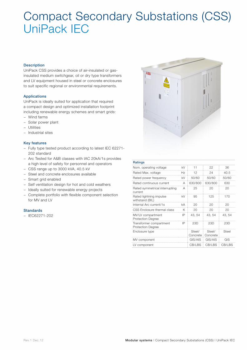
Rev.1 Dec.12 Modular systems | Compact Secondary Substations (CSS) | UniPack IEC
DescriptionUniPack CSS provides a choice of air-insulated or gas-insulated medium switchgear, oil or dry type transformers and LV equipment housed in steel or concrete enclosures to suit specific regional or environmental requirements.
ApplicationsUniPack is ideally suited for application that required a compact design and optimized installation footprint including renewable energy schemes and smart grids:
− Wind farms − Solar power plant − Utilities − Industrial sites
Key features
− Fully type tested product according to latest IEC 62271-202 standard
− Arc Tested for A&B classes with IAC 20kA/1s provides a high level of safety for personnel and operators
− CSS range up to 3000 kVA, 40.5 kV − Steel and concrete enclosures available − Smart grid enabled − Self ventilation design for hot and cold weathers − Ideally suited for renewable energy projects − Complete portfolio with flexible component selection
for MV and LV
Standards − IEC62271-202
Compact Secondary Substations (CSS)UniPack IEC
Ratings
Nom. operating voltage kV 11 22 36
Rated Max. voltage Hz 12 24 40.5
Rated power frequency kV 50/60 50/60 50/60
Rated continuous current A 630/800 630/800 630
Rated symmetrical interrupting current
A 25 20 20
Rated lightning impulse withstand (BIL)
kV 95 125 170
Internal Arc current/1s kA 20 20 20
CSS Enclosure thermal class K 20 20 20
MV/LV compartment Protection Degree
IP 43, 54 43, 54 43, 54
Transformer compartment Protection Degree
IP 23D 23D 23D
Enclosure type Steel/Concrete
Steel/Concrete
Steel
MV component GIS/AIS GIS/AIS GIS
LV component CB/LBS CB/LBS CB/LBS
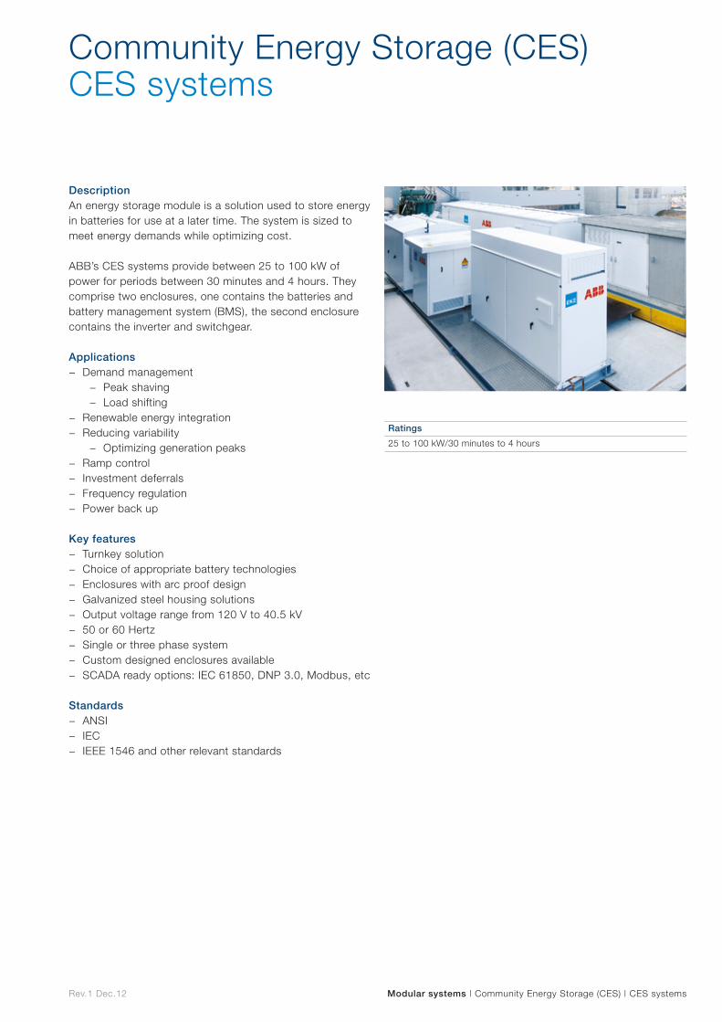
Rev.1 Dec.12 Modular systems | Community Energy Storage (CES) | CES systems
DescriptionAn energy storage module is a solution used to store energy in batteries for use at a later time. The system is sized to meet energy demands while optimizing cost.
ABB’s CES systems provide between 25 to 100 kW of power for periods between 30 minutes and 4 hours. They comprise two enclosures, one contains the batteries and battery management system (BMS), the second enclosure contains the inverter and switchgear.
Applications − Demand management
− Peak shaving − Load shifting
− Renewable energy integration − Reducing variability
− Optimizing generation peaks − Ramp control − Investment deferrals − Frequency regulation − Power back up
Key features − Turnkey solution − Choice of appropriate battery technologies − Enclosures with arc proof design − Galvanized steel housing solutions − Output voltage range from 120 V to 40.5 kV − 50 or 60 Hertz − Single or three phase system − Custom designed enclosures available − SCADA ready options: IEC 61850, DNP 3.0, Modbus, etc
Standards − ANSI − IEC − IEEE 1546 and other relevant standards
Community Energy Storage (CES) CES systems
Ratings
25 to 100 kW/30 minutes to 4 hours
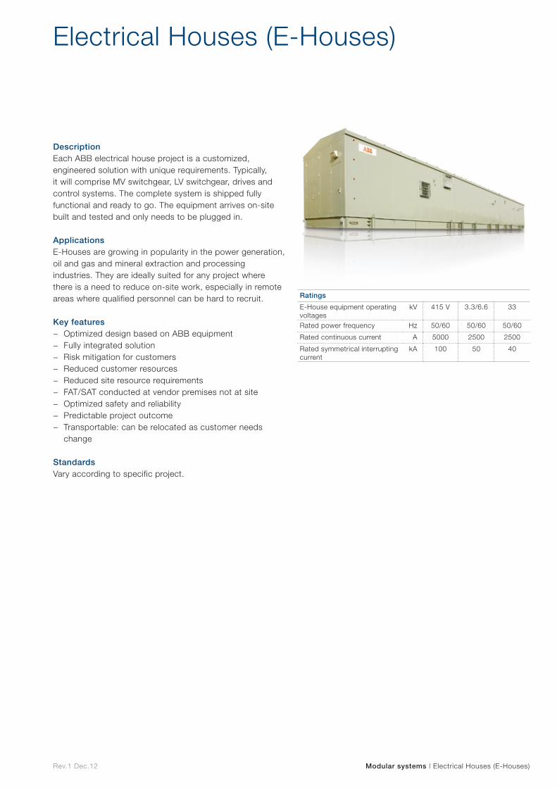
Rev.1 Dec.12 Modular systems | Electrical Houses (E-Houses)
DescriptionEach ABB electrical house project is a customized, engineered solution with unique requirements. Typically, it will comprise MV switchgear, LV switchgear, drives and control systems. The complete system is shipped fully functional and ready to go. The equipment arrives on-site built and tested and only needs to be plugged in.
Applications E-Houses are growing in popularity in the power generation, oil and gas and mineral extraction and processing industries. They are ideally suited for any project where there is a need to reduce on-site work, especially in remote areas where qualified personnel can be hard to recruit.
Key features − Optimized design based on ABB equipment − Fully integrated solution − Risk mitigation for customers − Reduced customer resources − Reduced site resource requirements − FAT/SAT conducted at vendor premises not at site − Optimized safety and reliability − Predictable project outcome − Transportable: can be relocated as customer needs
change
StandardsVary according to specific project.
Electrical Houses (E-Houses)
Ratings
E-House equipment operating voltages
kV 415 V 3.3/6.6 33
Rated power frequency Hz 50/60 50/60 50/60
Rated continuous current A 5000 2500 2500
Rated symmetrical interrupting current
kA 100 50 40

Surge arresters
Surg
e arresters
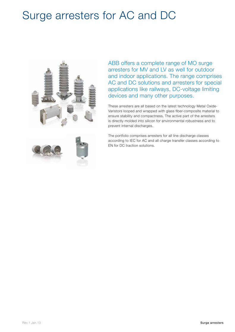
Rev.1 Jan.13
ABB offers a complete range of MO surge arresters for MV and LV as well for outdoor and indoor applications. The range comprises AC and DC solutions and arresters for special applications like railways, DC-voltage limiting devices and many other purposes.
Surge arresters for AC and DC
Surge arresters
These arresters are all based on the latest technology Metal Oxide-Varistors looped and wrapped with glass fiber-composite material to ensure stability and compactness. The active part of the arresters is directly molded into silicon for environmental robustness and to prevent internal discharges.
The portfolio comprises arresters for all line discharge classes according to IEC for AC and all charge transfer classes according to EN for DC traction solutions.
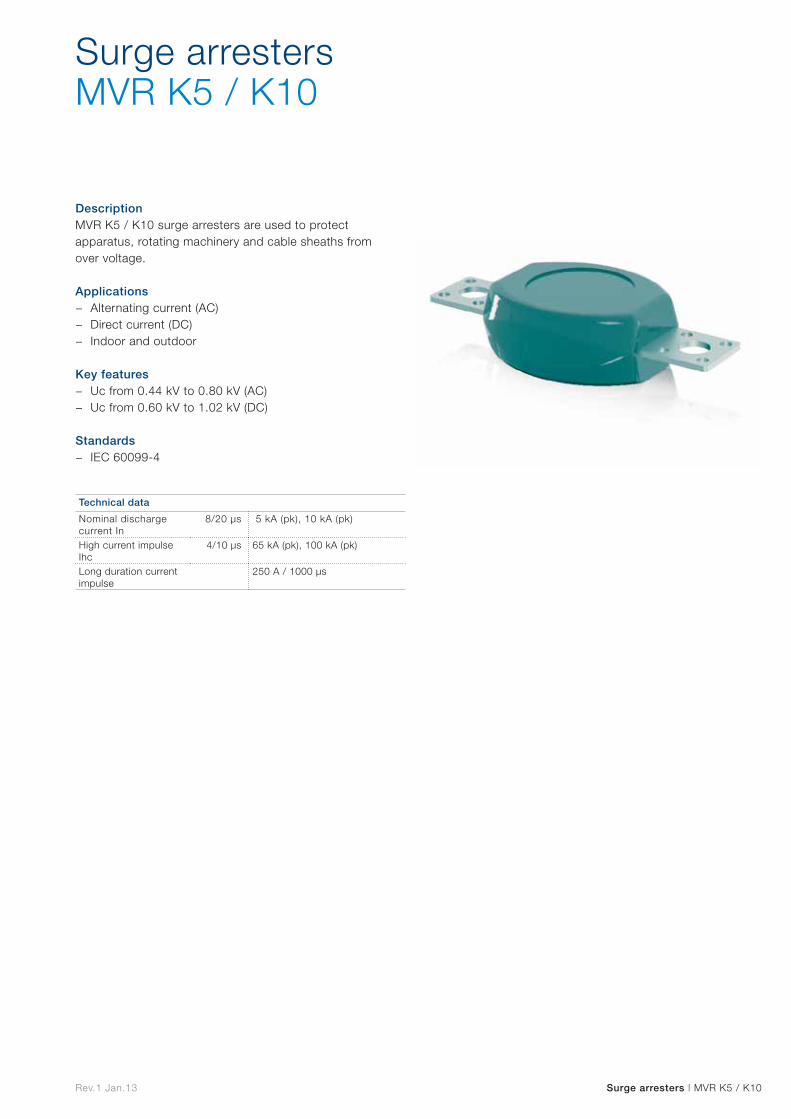
Rev.1 Jan.13 Surge arresters | MVR K5 / K10
DescriptionMVR K5 / K10 surge arresters are used to protect apparatus, rotating machinery and cable sheaths from over voltage.
Applications − Alternating current (AC) − Direct current (DC) − Indoor and outdoor
Key features − Uc from 0.44 kV to 0.80 kV (AC) − Uc from 0.60 kV to 1.02 kV (DC)
Standards − IEC 60099-4
Surge arrestersMVR K5 / K10
Technical data
Nominal discharge current In
8/20 µs 5 kA (pk), 10 kA (pk)
High current impulse Ihc
4/10 µs 65 kA (pk), 100 kA (pk)
Long duration current impulse
250 A / 1000 µs
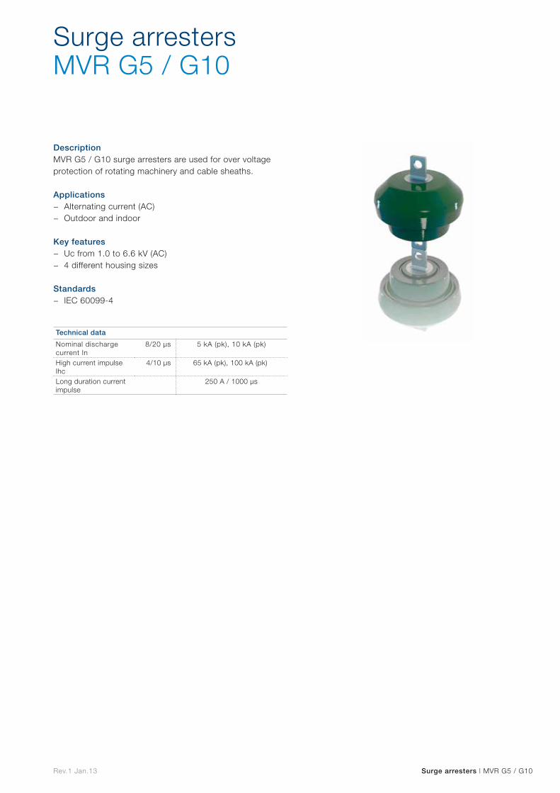
Rev.1 Jan.13 Surge arresters | MVR G5 / G10
DescriptionMVR G5 / G10 surge arresters are used for over voltage protection of rotating machinery and cable sheaths.
Applications − Alternating current (AC) − Outdoor and indoor
Key features − Uc from 1.0 to 6.6 kV (AC) − 4 different housing sizes
Standards − IEC 60099-4
Surge arrestersMVR G5 / G10
Technical data
Nominal discharge current In
8/20 µs 5 kA (pk), 10 kA (pk)
High current impulse Ihc
4/10 µs 65 kA (pk), 100 kA (pk)
Long duration current impulse
250 A / 1000 µs
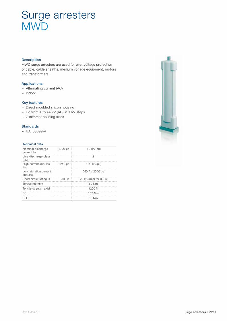
Rev.1 Jan.13 Surge arresters | MWD
DescriptionMWD surge arresters are used for over voltage protection of cable, cable sheaths, medium voltage equipment, motors and transformers.
Applications − Alternating current (AC) − Indoor
Key features − Direct moulded silicon housing − Uc from 4 to 44 kV (AC) in 1 kV steps − 7 different housing sizes
Standards − IEC 60099-4
Surge arrestersMWD
Technical data
Nominal discharge current In
8/20 µs 10 kA (pk)
Line discharge class (LD)
2
High current impulse Ihc
4/10 µs 100 kA (pk)
Long duration current impulse
550 A / 2000 µs
Short circuit rating Is 50 Hz 20 kA (rms) for 0.2 s
Torque moment 50 Nm
Tensile strength axial 1200 N
SSL 153 Nm
SLL 88 Nm
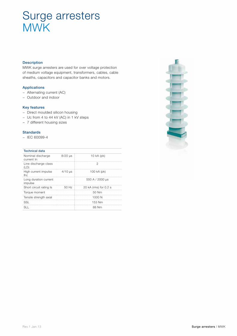
Rev.1 Jan.13 Surge arresters | MWK
DescriptionMWK surge arresters are used for over voltage protection of medium voltage equipment, transformers, cables, cable sheaths, capacitors and capacitor banks and motors.
Applications − Alternating current (AC) − Outdoor and indoor
Key features − Direct moulded silicon housing − Uc from 4 to 44 kV (AC) in 1 kV steps − 7 different housing sizes
Standards − IEC 60099-4
Surge arrestersMWK
Technical data
Nominal discharge current In
8/20 µs 10 kA (pk)
Line discharge class (LD)
2
High current impulse Ihc
4/10 µs 100 kA (pk)
Long duration current impulse
550 A / 2000 µs
Short circuit rating Is 50 Hz 20 kA (rms) for 0.2 s
Torque moment 50 Nm
Tensile strength axial 1000 N
SSL 153 Nm
SLL 88 Nm
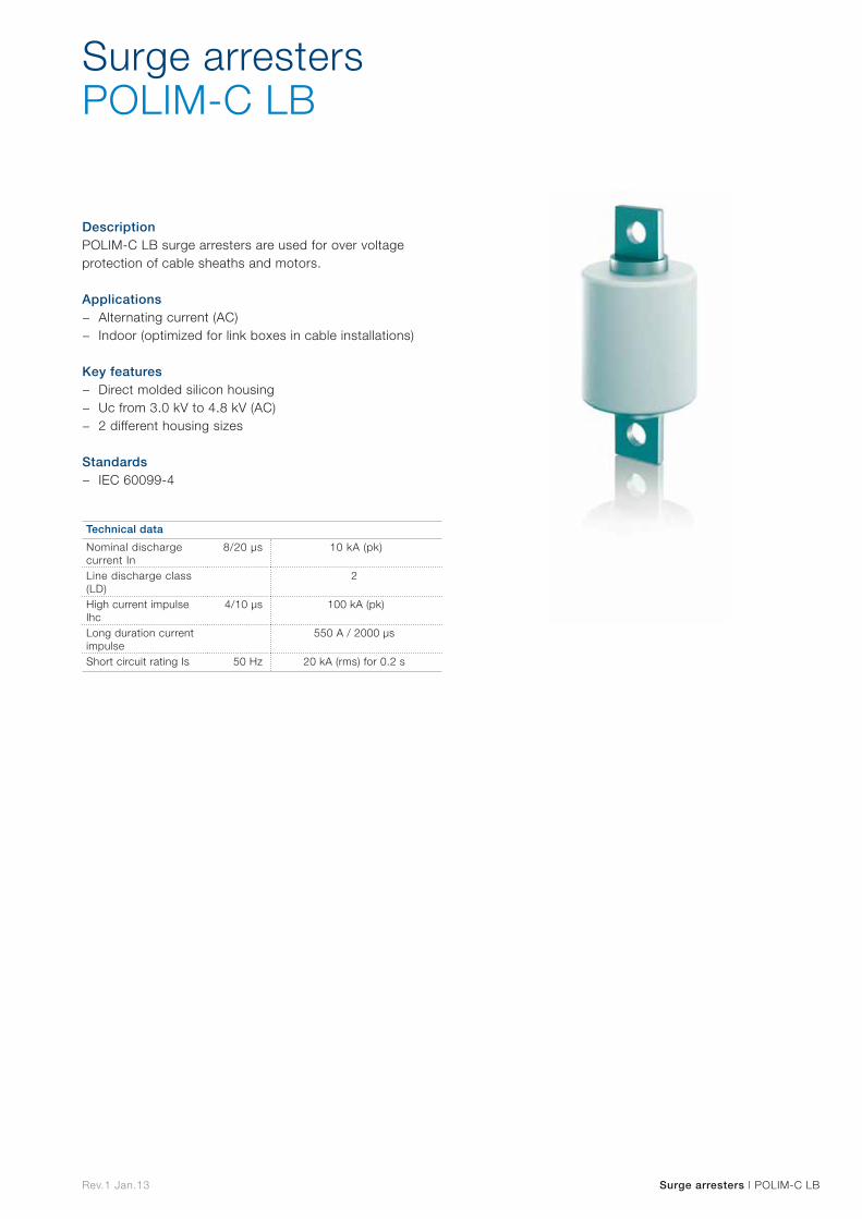
Rev.1 Jan.13 Surge arresters | POLIM-C LB
DescriptionPOLIM-C LB surge arresters are used for over voltage protection of cable sheaths and motors.
Applications − Alternating current (AC) − Indoor (optimized for link boxes in cable installations)
Key features − Direct molded silicon housing − Uc from 3.0 kV to 4.8 kV (AC) − 2 different housing sizes
Standards − IEC 60099-4
Surge arrestersPOLIM-C LB
Technical data
Nominal discharge current In
8/20 µs 10 kA (pk)
Line discharge class (LD)
2
High current impulse Ihc
4/10 µs 100 kA (pk)
Long duration current impulse
550 A / 2000 µs
Short circuit rating Is 50 Hz 20 kA (rms) for 0.2 s

Rev.1 Jan.13 Surge arresters | POLIM-C N
DescriptionPOLIM-C N surge arresters are used for over voltage protection of transformers, cable sheaths, secondary equipment and motors.
Applications − Alternating current (AC) − Outdoor and indoor
Key features − Direct molded silicon housing − Uc from 0.9 to 7.5 kV (AC) − 3 different housing sizes
Standards − IEC 60099-4
Surge arrestersPOLIM-C N
Technical data
Nominal discharge current In
8/20 µs 10 kA (pk)
Charge transfer classLine discharge class
DC - A (accounting EN - 50526-1)2 (according to IEC)
High current impulse Ihc
4/10 µs 100 kA (pk)
Long duration current impulse
550 A / 2000 µs
Short circuit rating Is 50 Hz 20 kA (rms) for 0.2 s
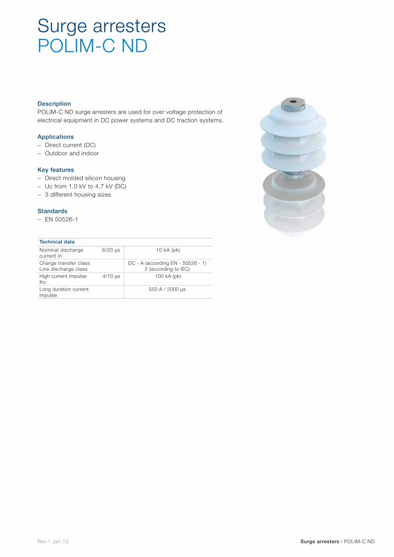
Rev.1 Jan.13 Surge arresters | POLIM-C ND
DescriptionPOLIM-C ND surge arresters are used for over voltage protection of electrical equipment in DC power systems and DC traction systems.
Applications − Direct current (DC) − Outdoor and indoor
Key features − Direct molded silicon housing − Uc from 1.0 kV to 4.7 kV (DC) − 3 different housing sizes
Standards − EN 50526-1
Surge arrestersPOLIM-C ND
Technical data
Nominal discharge current In
8/20 µs 10 kA (pk)
Charge transfer class Line discharge class
DC - A (according EN - 50526 - 1) 2 (according to IEC)
High current impulse Ihc
4/10 µs 100 kA (pk)
Long duration current impulse
550 A / 2000 µs
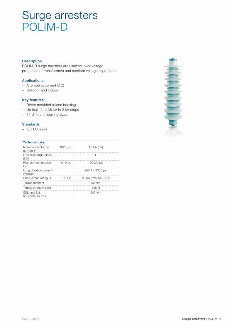
Rev.1 Jan.13 Surge arresters | POLIM-D
DescriptionPOLIM-D surge arresters are used for over voltage protection of transformers and medium voltage equipment.
Applications − Alternating current (AC) − Outdoor and indoor
Key features − Direct moulded silicon housing − Uc from 4 to 36 kV in 2 kV steps − 11 different housing sizes
Standards − IEC 60099-4
Surge arrestersPOLIM-D
Technical data
Nominal discharge current In
8/20 µs 10 kA (pk)
Line discharge class (LD)
1
High current impulse Ihc
4/10 µs 100 kA (pk)
Long duration current impulse
250 A / 2000 µs
Short circuit rating Is 50 Hz 20 kA (rms) for 0.2 s
Torque moment 50 Nm
Tensile strength axial 625 N
SSL and SLL horizontal to axis
207 Nm
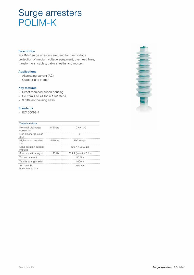
Rev.1 Jan.13 Surge arresters | POLIM-K
DescriptionPOLIM-K surge arresters are used for over voltage protection of medium voltage equipment, overhead lines, transformers, cables, cable sheaths and motors.
Applications − Alternating current (AC) − Outdoor and indoor
Key features − Direct moulded silicon housing − Uc from 4 to 44 kV in 1 kV steps − 9 different housing sizes
Standards − IEC 60099-4
Surge arrestersPOLIM-K
Technical data
Nominal discharge current In
8/20 µs 10 kA (pk)
Line discharge class (LD)
2
High current impulse Ihc
4/10 µs 100 kA (pk)
Long duration current impulse
500 A / 2000 µs
Short circuit rating Is 50 Hz 50 kA (rms) for 0.2 s
Torque moment 50 Nm
Tensile strength axial 1000 N
SSL and SLL horizontal to axis
250 Nm
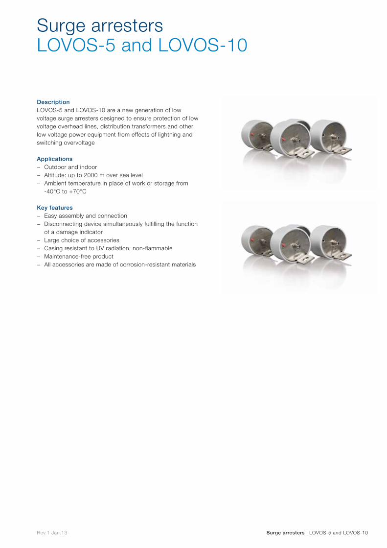
Rev.1 Jan.13 Surge arresters | LOVOS-5 and LOVOS-10
DescriptionLOVOS-5 and LOVOS-10 are a new generation of low voltage surge arresters designed to ensure protection of low voltage overhead lines, distribution transformers and other low voltage power equipment from effects of lightning and switching overvoltage
Applications − Outdoor and indoor − Altitude: up to 2000 m over sea level − Ambient temperature in place of work or storage from
-40°C to +70°C
Key features − Easy assembly and connection − Disconnecting device simultaneously fulfilling the function
of a damage indicator − Large choice of accessories − Casing resistant to UV radiation, non-flammable − Maintenance-free product − All accessories are made of corrosion-resistant materials
Surge arrestersLOVOS-5 and LOVOS-10
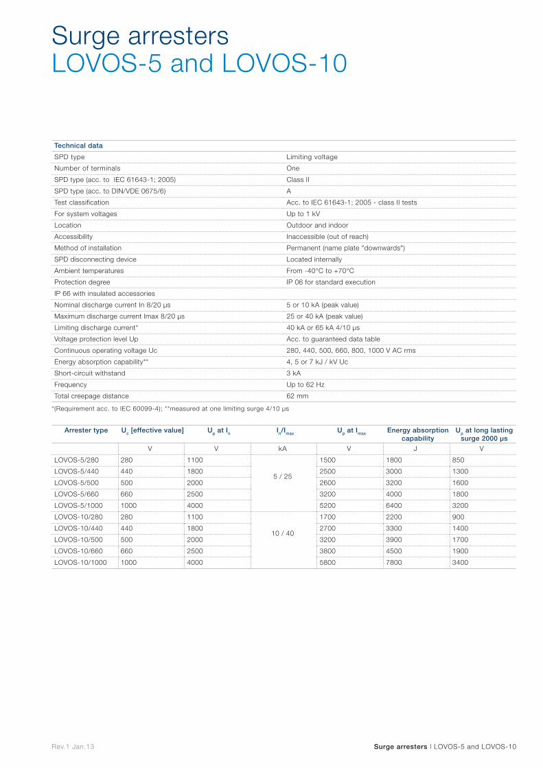
Rev.1 Jan.13 Surge arresters | LOVOS-5 and LOVOS-10
Technical data
SPD type Limiting voltage
Number of terminals One
SPD type (acc. to IEC 61643-1; 2005) Class II
SPD type (acc. to DIN/VDE 0675/6) A
Test classification Acc. to IEC 61643-1; 2005 - class II tests
For system voltages Up to 1 kV
Location Outdoor and indoor
Accessibility Inaccessible (out of reach)
Method of installation Permanent (name plate "downwards")
SPD disconnecting device Located internally
Ambient temperatures From -40°C to +70°C
Protection degree IP 06 for standard execution
IP 66 with insulated accessories
Nominal discharge current In 8/20 µs 5 or 10 kA (peak value)
Maximum discharge current Imax 8/20 µs 25 or 40 kA (peak value)
Limiting discharge current* 40 kA or 65 kA 4/10 µs
Voltage protection level Up Acc. to guaranteed data table
Continuous operating voltage Uc 280, 440, 500, 660, 800, 1000 V AC rms
Energy absorption capability** 4, 5 or 7 kJ / kV Uc
Short-circuit withstand 3 kA
Frequency Up to 62 Hz
Total creepage distance 62 mm
Arrester type Uc [effective value] Up at In In/Imax Up at Imax Energy absorption capability
Up at long lasting surge 2000 μs
V V kA V J V
LOVOS-5/280 280 1100
5 / 25
1500 1800 850
LOVOS-5/440 440 1800 2500 3000 1300
LOVOS-5/500 500 2000 2600 3200 1600
LOVOS-5/660 660 2500 3200 4000 1800
LOVOS-5/1000 1000 4000 5200 6400 3200
LOVOS-10/280 280 1100
10 / 40
1700 2200 900
LOVOS-10/440 440 1800 2700 3300 1400
LOVOS-10/500 500 2000 3200 3900 1700
LOVOS-10/660 660 2500 3800 4500 1900
LOVOS-10/1000 1000 4000 5800 7800 3400
*(Requirement acc. to IEC 60099-4); **measured at one limiting surge 4/10 µs
Surge arrestersLOVOS-5 and LOVOS-10

Switchgear
Sw
itchgear
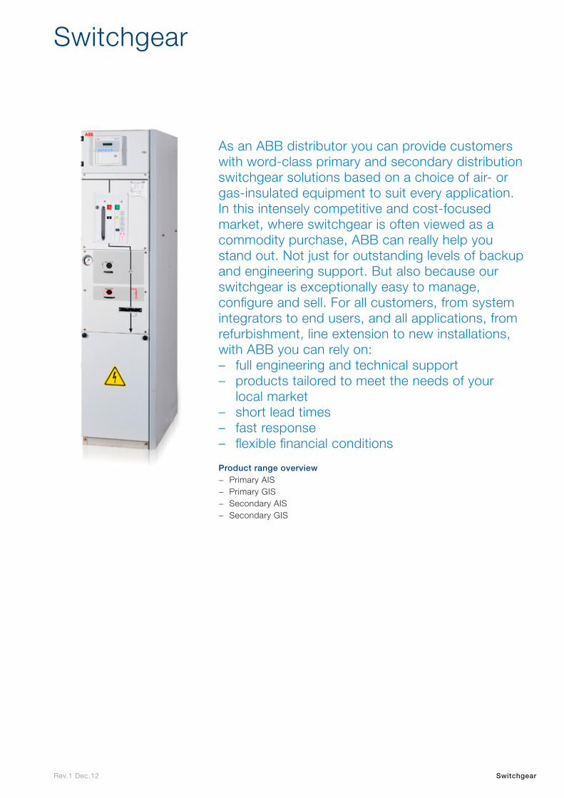
Rev.1 Dec.12 Switchgear
As an ABB distributor you can provide customers with word-class primary and secondary distribution switchgear solutions based on a choice of air- or gas-insulated equipment to suit every application. In this intensely competitive and cost-focused market, where switchgear is often viewed as a commodity purchase, ABB can really help you stand out. Not just for outstanding levels of backup and engineering support. But also because our switchgear is exceptionally easy to manage, configure and sell. For all customers, from system integrators to end users, and all applications, from refurbishment, line extension to new installations, with ABB you can rely on: – full engineering and technical support – products tailored to meet the needs of your
local market – short lead times – fast response – flexible financial conditions
Product range overview − Primary AIS − Primary GIS − Secondary AIS − Secondary GIS
Switchgear

Primary AIS distribution
Prim
ary A
IS
distrib
ution

Primary GIS distribution Prim
ary G
IS
distrib
ution

Secondary AIS distribution
Seco
ndary
AIS
d
istributio
n
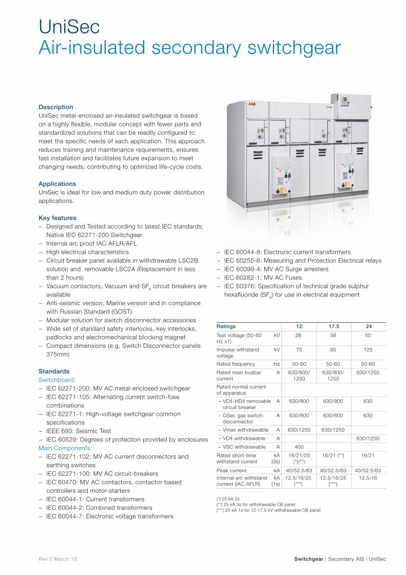
Rev.2 March.13 Switchgear | Secondary AIS | UniSec
UniSecAir-insulated secondary switchgear
DescriptionUniSec metal-enclosed air-insulated switchgear is based on a highly flexible, modular concept with fewer parts and standardized solutions that can be readily configured to meet the specific needs of each application. This approach reduces training and maintenance requirements, ensures fast installation and facilitates future expansion to meet changing needs, contributing to optimized life-cycle costs.
ApplicationsUniSec is ideal for low and medium duty power distribution applications.
Key features − Designed and Tested according to latest IEC standards;
Native IEC 62271-200 Switchgear − Internal arc proof IAC AFLR/AFL − High electrical characteristics − Circuit breaker panel available in withdrawable LSC2B
solution and removable LSC2A (Replacement in less than 2 hours)
− Vacuum contactors, Vacuum and SF6 circuit breakers are available
− Anti-seismic version, Marine version and in compliance with Russian Standard (GOST)
− Modular solution for switch disconnector accessories − Wide set of standard safety interlocks, key interlocks,
padlocks and electromechanical blocking magnet − Compact dimensions (e.g. Switch Disconnector panels
375mm)
StandardsSwitchboard:
− IEC 62271-200: MV AC metal-enclosed switchgear − IEC 62271-105: Alternating current switch-fuse
combinations − IEC 62271-1: High-voltage switchgear common
specifications − IEEE 693: Seismic Test − IEC 60529: Degrees of protection provided by enclosures
Main Components: − IEC 62271-102: MV AC current disconnectors and
earthing switches − IEC 62271-100: MV AC circuit-breakers − IEC 60470: MV AC contactors, contactor-based
controllers and motor-starters − IEC 60044-1: Current transformers − IEC 60044-2: Combined transformers − IEC 60044-7: Electronic voltage transformers
− IEC 60044-8: Electronic current transformers − IEC 60255-6: Measuring and Protection Electrical relays − IEC 60099-4: MV AC Surge arresters − IEC 60282-1: MV AC Fuses − IEC 60376: Specification of technical grade sulphur
hexafluoride (SF6) for use in electrical equipment
(*) 25 kA 2s(**) 25 kA 3s for withdrawable CB panel(***) 25 kA 1s for 12-17.5 kV withdrawable CB panel
Ratings 12 17.5 24
Test voltage (50-60 Hz x1)
kV 28 38 50
Impulse withstand voltage
kV 75 95 125
Rated frequency Hz 50-60 50-60 50-60
Rated main busbar current
A 630/800/ 1250
630/800/ 1250
630/1250
Rated normal current of apparatus
– VD4-HD4 removable circuit breaker
A 630/800 630/800 630
– GSec gas switch-disconnector
A 630/800 630/800 630
– Vmax withdrawable A 630/1250 630/1250
– VD4 withdrawable A 630/1250
– VSC withdrawable A 400
Rated short-time withstand current
kA (3s)
16/21/25 (*)(**)
16/21 (**) 16/21
Peak current kA 40/52.5/63 40/52.5/63 40/52.5/63Internal arc withstand current (IAC AFLR)
kA (1s)
12.5/16/25 (***)
12.5/16/25 (***)
12.5/16

Secondary GIS distribution
Seco
ndary
GIS
d
istributio
n
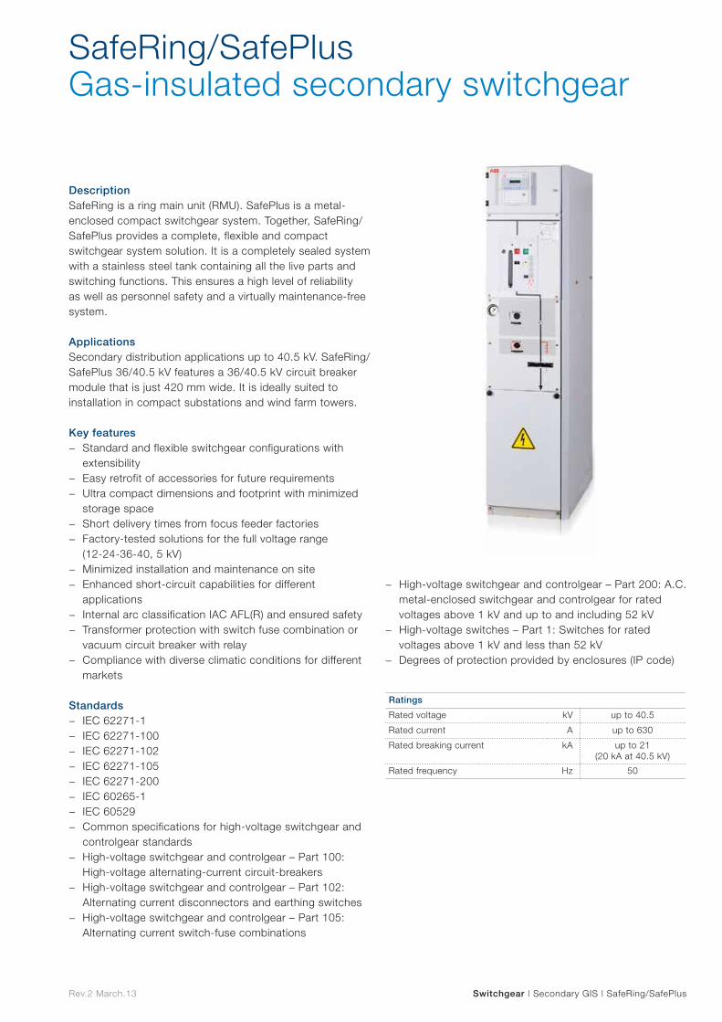
Rev.2 March.13 Switchgear | Secondary GIS | SafeRing/SafePlus
SafeRing/SafePlus Gas-insulated secondary switchgear
DescriptionSafeRing is a ring main unit (RMU). SafePlus is a metal-enclosed compact switchgear system. Together, SafeRing/SafePlus provides a complete, flexible and compact switchgear system solution. It is a completely sealed system with a stainless steel tank containing all the live parts and switching functions. This ensures a high level of reliability as well as personnel safety and a virtually maintenance-free system.
ApplicationsSecondary distribution applications up to 40.5 kV. SafeRing/SafePlus 36/40.5 kV features a 36/40.5 kV circuit breaker module that is just 420 mm wide. It is ideally suited to installation in compact substations and wind farm towers.
Key features − Standard and flexible switchgear configurations with
extensibility − Easy retrofit of accessories for future requirements − Ultra compact dimensions and footprint with minimized
storage space − Short delivery times from focus feeder factories − Factory-tested solutions for the full voltage range
(12-24-36-40, 5 kV) − Minimized installation and maintenance on site − Enhanced short-circuit capabilities for different
applications − Internal arc classification IAC AFL(R) and ensured safety − Transformer protection with switch fuse combination or
vacuum circuit breaker with relay − Compliance with diverse climatic conditions for different
markets
Standards − IEC 62271-1 − IEC 62271-100 − IEC 62271-102 − IEC 62271-105 − IEC 62271-200 − IEC 60265-1 − IEC 60529 − Common specifications for high-voltage switchgear and
controlgear standards − High-voltage switchgear and controlgear – Part 100:
High-voltage alternating-current circuit-breakers − High-voltage switchgear and controlgear – Part 102:
Alternating current disconnectors and earthing switches − High-voltage switchgear and controlgear – Part 105:
Alternating current switch-fuse combinations
− High-voltage switchgear and controlgear – Part 200: A.C. metal-enclosed switchgear and controlgear for rated voltages above 1 kV and up to and including 52 kV
− High-voltage switches – Part 1: Switches for rated voltages above 1 kV and less than 52 kV
− Degrees of protection provided by enclosures (IP code)
Ratings
Rated voltage kV up to 40.5
Rated current A up to 630
Rated breaking current kA up to 21 (20 kA at 40.5 kV)
Rated frequency Hz 50

Switches/Reclosers/Sectionalizers
Sw
itches/R
eclosers/
Sectio
nalizers
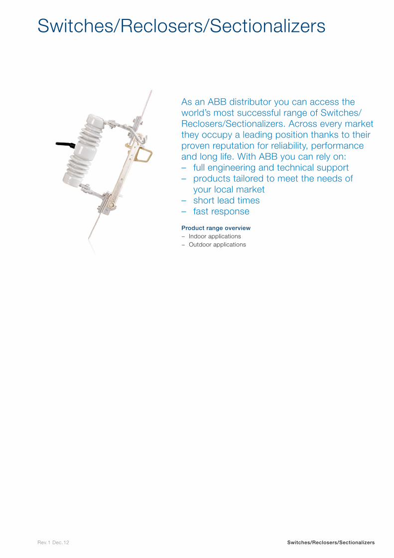
Rev.1 Dec.12 Switches/Reclosers/Sectionalizers
Switches/Reclosers/Sectionalizers
As an ABB distributor you can access the world’s most successful range of Switches/Reclosers/Sectionalizers. Across every market they occupy a leading position thanks to their proven reputation for reliability, performance and long life. With ABB you can rely on: – full engineering and technical support – products tailored to meet the needs of
your local market – short lead times – fast response
Product range overview − Indoor applications − Outdoor applications

Indoor applications
Indo
or
app
lications
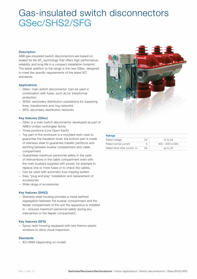
Rev.1 Dec.12 Switches/Reclosers/Sectionalizers | Indoor applications | Switch disconnectors | GSec/SHS2/SFG
DescriptionABB gas-insulated switch disconnectors are based on sealed for life SF6 technology that offers high performance, reliability and long-life in a compact installation footprint. The latest addition to the range is the new GSec, designed to meet the specific requirements of the latest IEC standards.
Applications − GSec: main switch disconnector. Can be used in
combination with fuses, such as for transformer protection
− SHS2: secondary distribution substations for supplying lines, transformers and ring networks
− SFG: secondary distribution networks
Key features (GSec) − GSec is a main switch disconnector developed as part of
ABB’s UniSec switchgear family − Three-positions (Line-Open-Earth) − Top part of the enclosure is a moulded resin case to
guarantee the insulation level; the bottom part is made of stainless steel to guarantee metallic partitions and earthing between busbar compartment and cable compartment
− Guarantees maximum personnel safety in the case of interventions in the cable compartment even with the main busbars supplied with power, for example to replace one or more fuses or to check the cables.
− Can be used with automatic fuse tripping system − Easy “plug and play” installation and replacement of
accessories − Wide range of accessories
Key features (SHS2) − Stainless steel housing provides a metal earthed
segregation between the busbar compartment and the feeder compartment of the unit the apparatus is installed in – ensures maximum personnel safety during any intervention in the feeder compartment.
Key features (SFG) − Epoxy resin housing equipped with two thermo plastic
windows to allow visual inspection.
Standards − IEC/ANSI (depending on model)
Gas-insulated switch disconnectorsGSec/SHS2/SFG
Ratings
Rated voltage kV 12 to 24
Rated normal current A 400 – 630 to 800
Rated short-time current 1s kA up to 20
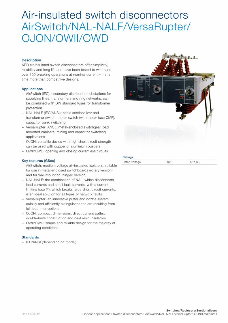
Rev.1 Dec.12Switches/Reclosers/Sectionalizers
| Indoor applications | Switch disconnectors | AirSwitch/NAL-NALF/VersaRupter/OJON/OWII/OWD
DescriptionABB air-insulated switch disconnectors offer simplicity, reliability and long life and have been tested to withstand over 100 breaking operations at nominal current – many time more than competitive designs.
Applications − AirSwitch (IEC): secondary distribution substations for
supplying lines, transformers and ring networks, can be combined with DIN standard fuses for transformer protection.
− NAL-NALF (IEC/ANSI): cable sectionalizer and transformer switch, motor switch (with motor fuse CMF), capacitor bank switching
− VersaRupter (ANSI): metal-enclosed switchgear, pad mounted cabinets, mining and capacitor switching applications
− OJON: versatile device with high short circuit strength can be used with copper or aluminium busbars
− OWII/OWD: opening and closing currentless circuits
Key features (GSec) − AirSwitch: medium voltage air-insulated isolators, suitable
for use in metal-enclosed switchboards (rotary version) and for wall-mounting (hinged version)
− NAL-NALF: the combination of NAL, which disconnects load currents and small fault currents, with a current limiting fuse (F), which breaks large short circuit currents, is an ideal solution for all types of network faults
− VersaRupter: an innovative puffer and nozzle system quickly and efficiently extinguishes the arc resulting from full-load interruptions
− OJON: compact dimensions, direct current paths, double-knife construction and cast resin insulators
− OWII/OWD: simple and reliable design for the majority of operating conditions
Standards − IEC/ANSI (depending on model)
Air-insulated switch disconnectors AirSwitch/NAL-NALF/VersaRupter/OJON/OWII/OWD
Ratings
Rated voltage kV 5 to 38
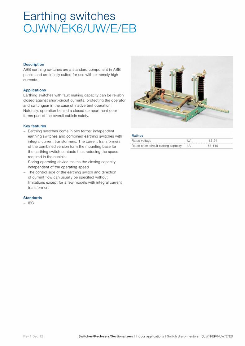
Rev.1 Dec.12 Switches/Reclosers/Sectionalizers | Indoor applications | Switch disconnectors | OJWN/EK6/UW/E/EB
DescriptionABB earthing switches are a standard component in ABB panels and are ideally suited for use with extremely high currents.
ApplicationsEarthing switches with fault making capacity can be reliably closed against short-circuit currents, protecting the operator and switchgear in the case of inadvertent operation. Naturally, operation behind a closed compartment door forms part of the overall cubicle safety.
Key features − Earthing switches come in two forms: independent
earthing switches and combined earthing switches with integral current transformers. The current transformers of the combined version form the mounting base for the earthing switch contacts thus reducing the space required in the cubicle
− Spring operating device makes the closing capacity independent of the operating speed
− The control side of the earthing switch and direction of current flow can usually be specified without limitations except for a few models with integral current transformers
Standards − IEC
Earthing switches OJWN/EK6/UW/E/EB
Ratings
Rated voltage kV 12-24
Rated short-circuit closing capacity kA 63-110

Outdoor applications Outd
oo
r ap
plicatio
ns
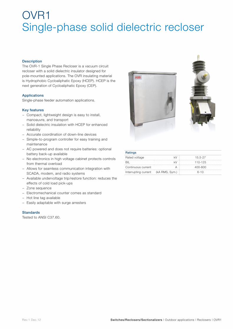
Rev.1 Dec.12 Switches/Reclosers/Sectionalizers | Outdoor applications | Reclosers | OVR1
DescriptionThe OVR-1 Single Phase Recloser is a vacuum circuit recloser with a solid dielectric insulator designed for pole-mounted applications. The OVR insulating material is Hydrophobic Cycloaliphatic Epoxy (HCEP). HCEP is the next generation of Cycloaliphatic Epoxy (CEP).
ApplicationsSingle-phase feeder automation applications.
Key features − Compact, lightweight design is easy to install,
manoeuvre, and transport − Solid dielectric insulation with HCEP for enhanced
reliability − Accurate coordination of down-line devices − Simple-to-program controller for easy training and
maintenance − AC powered and does not require batteries: optional
battery back-up available − No electronics in high voltage cabinet protects controls
from thermal overload − Allows for seamless communication integration with
SCADA, modem, and radio systems − Available undervoltage trip/restore function: reduces the
effects of cold load pick-ups − Zone sequence − Electromechanical counter comes as standard − Hot line tag available − Easily adaptable with surge arresters
StandardsTested to ANSI C37.60.
OVR1Single-phase solid dielectric recloser
Ratings
Rated voltage kV 15.5-27
BIL kV 110-125
Continuous current A 400-800
Interrupting current (kA RMS, Sym.) 6-10
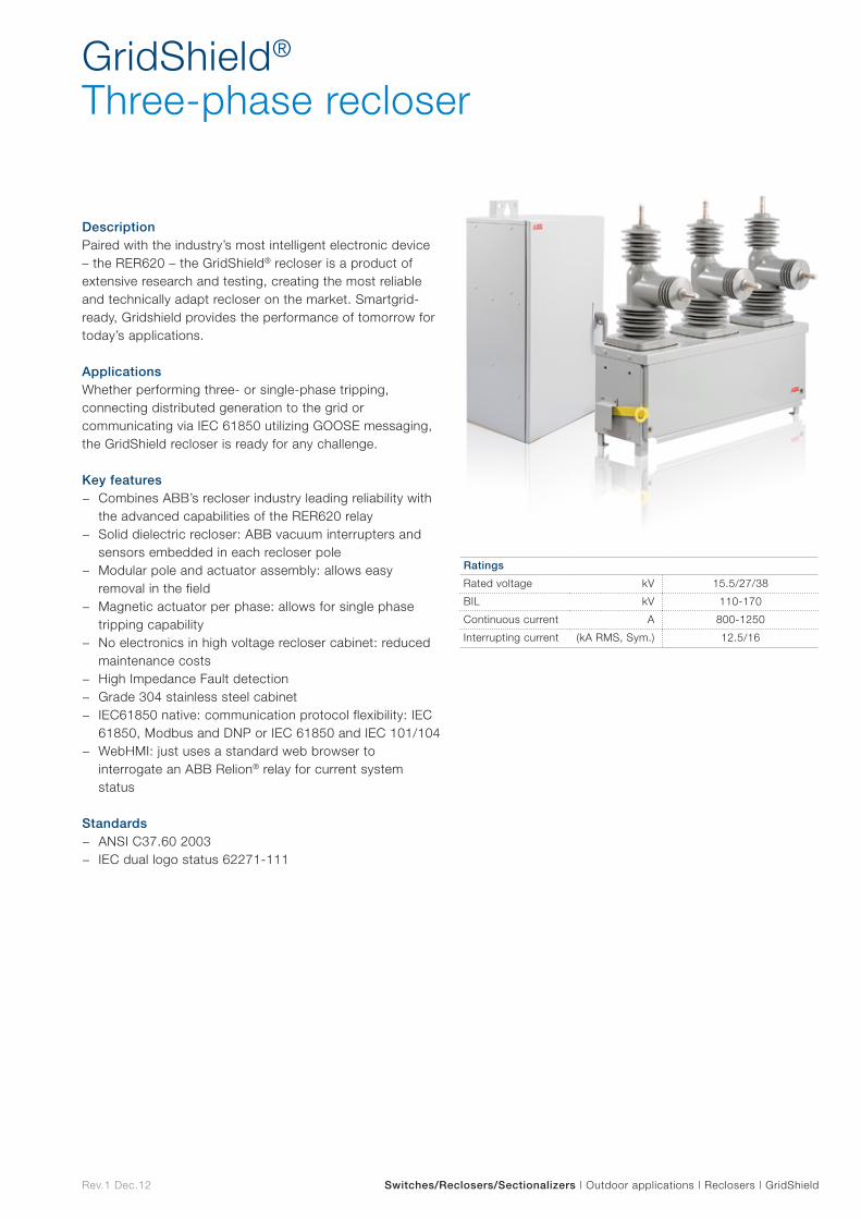
Rev.1 Dec.12 Switches/Reclosers/Sectionalizers | Outdoor applications | Reclosers | GridShield
DescriptionPaired with the industry’s most intelligent electronic device – the RER620 – the GridShield® recloser is a product of extensive research and testing, creating the most reliable and technically adapt recloser on the market. Smartgrid-ready, Gridshield provides the performance of tomorrow for today’s applications.
ApplicationsWhether performing three- or single-phase tripping, connecting distributed generation to the grid or communicating via IEC 61850 utilizing GOOSE messaging, the GridShield recloser is ready for any challenge.
Key features − Combines ABB’s recloser industry leading reliability with
the advanced capabilities of the RER620 relay − Solid dielectric recloser: ABB vacuum interrupters and
sensors embedded in each recloser pole − Modular pole and actuator assembly: allows easy
removal in the field − Magnetic actuator per phase: allows for single phase
tripping capability − No electronics in high voltage recloser cabinet: reduced
maintenance costs − High Impedance Fault detection − Grade 304 stainless steel cabinet − IEC61850 native: communication protocol flexibility: IEC
61850, Modbus and DNP or IEC 61850 and IEC 101/104 − WebHMI: just uses a standard web browser to
interrogate an ABB Relion® relay for current system status
Standards − ANSI C37.60 2003 − IEC dual logo status 62271-111
GridShield®
Three-phase recloser
Ratings
Rated voltage kV 15.5/27/38
BIL kV 110-170
Continuous current A 800-1250
Interrupting current (kA RMS, Sym.) 12.5/16
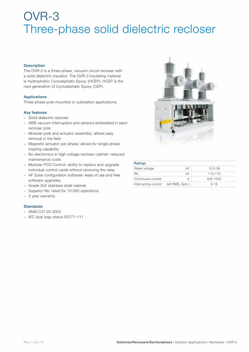
Rev.1 Dec.12 Switches/Reclosers/Sectionalizers | Outdoor applications | Reclosers | OVR-3
DescriptionThe OVR-3 is a three-phase, vacuum circuit recloser with a solid dielectric insulator. The OVR-3 insulating material is Hydrophobic Cycloaliphatic Epoxy (HCEP). HCEP is the next generation of Cycloaliphatic Epoxy (CEP).
ApplicationsThree-phase pole-mounted or substation applications.
Key features − Solid dielectric recloser − ABB vacuum interrupters and sensors embedded in each
recloser pole − Modular pole and actuator assembly: allows easy
removal in the field − Magnetic actuator per phase: allows for single phase
tripping capability − No electronics in high voltage recloser cabinet: reduced
maintenance costs − Modular PCD Control: ability to replace and upgrade
individual control cards without removing the relay − AF Suite configuration software: ease of use and free
software upgrades − Grade 304 stainless steel cabinet − Superior life: rated for 10,000 operations − 3 year warranty
Standards − ANSI C37.60 2003 − IEC dual logo status 62271-111
OVR-3Three-phase solid dielectric recloser
Ratings
Rated voltage kV 15.5-38
BIL kV 110-170
Continuous current A 630-1250
Interrupting current (kA RMS, Sym.) 8-16
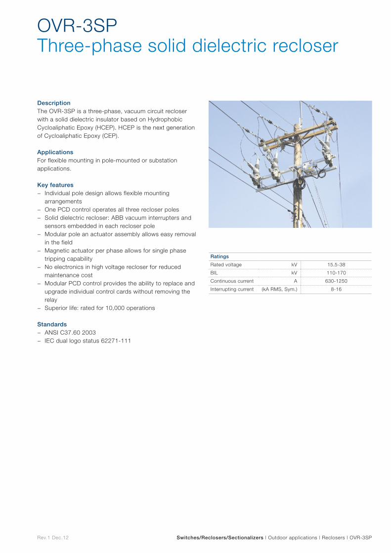
Rev.1 Dec.12 Switches/Reclosers/Sectionalizers | Outdoor applications | Reclosers | OVR-3SP
DescriptionThe OVR-3SP is a three-phase, vacuum circuit recloser with a solid dielectric insulator based on Hydrophobic Cycloaliphatic Epoxy (HCEP). HCEP is the next generation of Cycloaliphatic Epoxy (CEP).
ApplicationsFor flexible mounting in pole-mounted or substation applications.
Key features − Individual pole design allows flexible mounting
arrangements − One PCD control operates all three recloser poles − Solid dielectric recloser: ABB vacuum interrupters and
sensors embedded in each recloser pole − Modular pole an actuator assembly allows easy removal
in the field − Magnetic actuator per phase allows for single phase
tripping capability − No electronics in high voltage recloser for reduced
maintenance cost − Modular PCD control provides the ability to replace and
upgrade individual control cards without removing the relay
− Superior life: rated for 10,000 operations
Standards − ANSI C37.60 2003 − IEC dual logo status 62271-111
OVR-3SPThree-phase solid dielectric recloser
Ratings
Rated voltage kV 15.5-38
BIL kV 110-170
Continuous current A 630-1250
Interrupting current (kA RMS, Sym.) 8-16
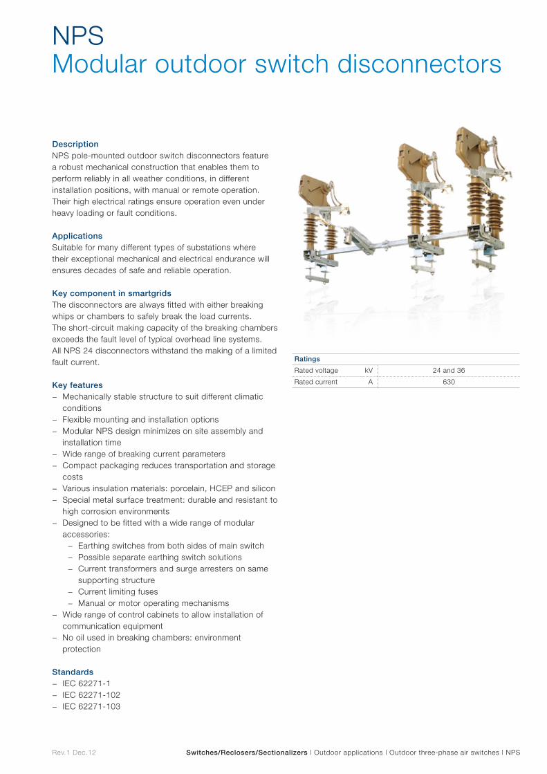
Rev.1 Dec.12 Switches/Reclosers/Sectionalizers | Outdoor applications | Outdoor three-phase air switches | NPS
NPS Modular outdoor switch disconnectors
DescriptionNPS pole-mounted outdoor switch disconnectors feature a robust mechanical construction that enables them to perform reliably in all weather conditions, in different installation positions, with manual or remote operation. Their high electrical ratings ensure operation even under heavy loading or fault conditions.
ApplicationsSuitable for many different types of substations where their exceptional mechanical and electrical endurance will ensures decades of safe and reliable operation.
Key component in smartgridsThe disconnectors are always fitted with either breaking whips or chambers to safely break the load currents. The short-circuit making capacity of the breaking chambers exceeds the fault level of typical overhead line systems. All NPS 24 disconnectors withstand the making of a limited fault current.
Key features − Mechanically stable structure to suit different climatic
conditions − Flexible mounting and installation options − Modular NPS design minimizes on site assembly and
installation time − Wide range of breaking current parameters − Compact packaging reduces transportation and storage
costs − Various insulation materials: porcelain, HCEP and silicon − Special metal surface treatment: durable and resistant to
high corrosion environments − Designed to be fitted with a wide range of modular
accessories: − Earthing switches from both sides of main switch − Possible separate earthing switch solutions − Current transformers and surge arresters on same
supporting structure − Current limiting fuses − Manual or motor operating mechanisms
− Wide range of control cabinets to allow installation of communication equipment
− No oil used in breaking chambers: environment protection
Standards − IEC 62271-1 − IEC 62271-102 − IEC 62271-103
Ratings
Rated voltage kV 24 and 36
Rated current A 630
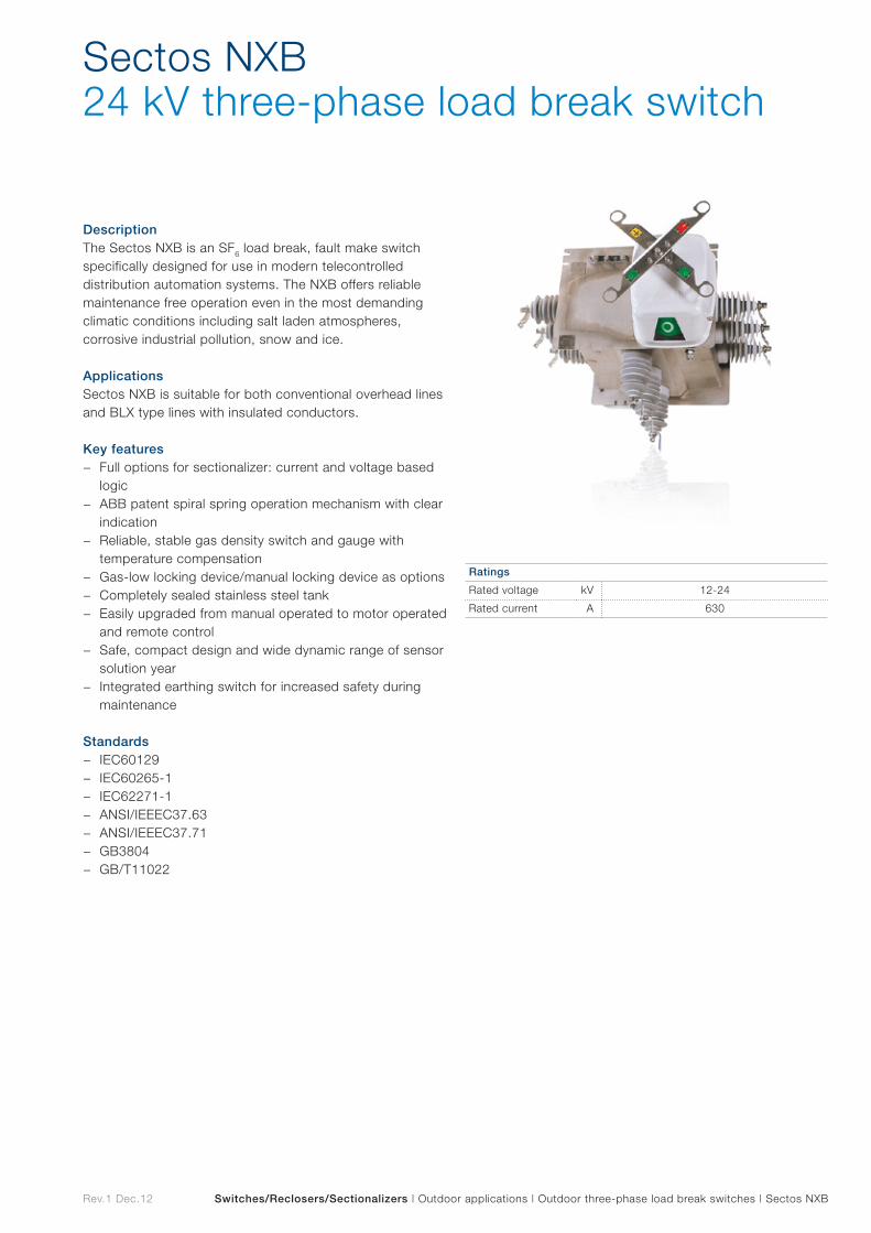
Rev.1 Dec.12 Switches/Reclosers/Sectionalizers | Outdoor applications | Outdoor three-phase load break switches | Sectos NXB
DescriptionThe Sectos NXB is an SF6 load break, fault make switch specifically designed for use in modern telecontrolled distribution automation systems. The NXB offers reliable maintenance free operation even in the most demanding climatic conditions including salt laden atmospheres, corrosive industrial pollution, snow and ice.
ApplicationsSectos NXB is suitable for both conventional overhead lines and BLX type lines with insulated conductors.
Key features − Full options for sectionalizer: current and voltage based
logic − ABB patent spiral spring operation mechanism with clear
indication − Reliable, stable gas density switch and gauge with
temperature compensation − Gas-low locking device/manual locking device as options − Completely sealed stainless steel tank − Easily upgraded from manual operated to motor operated
and remote control − Safe, compact design and wide dynamic range of sensor
solution year − Integrated earthing switch for increased safety during
maintenance
Standards − IEC60129 − IEC60265-1 − IEC62271-1 − ANSI/IEEEC37.63 − ANSI/IEEEC37.71 − GB3804 − GB/T11022
Sectos NXB 24 kV three-phase load break switch
Ratings
Rated voltage kV 12-24
Rated current A 630
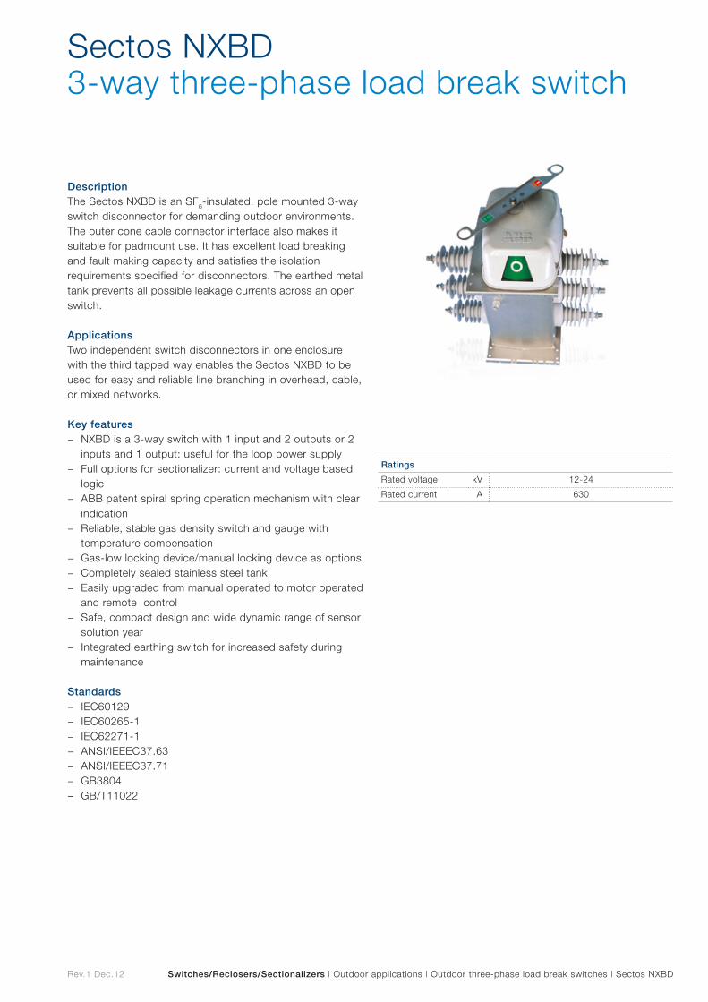
Rev.1 Dec.12 Switches/Reclosers/Sectionalizers | Outdoor applications | Outdoor three-phase load break switches | Sectos NXBD
DescriptionThe Sectos NXBD is an SF6-insulated, pole mounted 3-way switch disconnector for demanding outdoor environments. The outer cone cable connector interface also makes it suitable for padmount use. It has excellent load breaking and fault making capacity and satisfies the isolation requirements specified for disconnectors. The earthed metal tank prevents all possible leakage currents across an open switch.
ApplicationsTwo independent switch disconnectors in one enclosure with the third tapped way enables the Sectos NXBD to be used for easy and reliable line branching in overhead, cable, or mixed networks.
Key features − NXBD is a 3-way switch with 1 input and 2 outputs or 2
inputs and 1 output: useful for the loop power supply − Full options for sectionalizer: current and voltage based
logic − ABB patent spiral spring operation mechanism with clear
indication − Reliable, stable gas density switch and gauge with
temperature compensation − Gas-low locking device/manual locking device as options − Completely sealed stainless steel tank − Easily upgraded from manual operated to motor operated
and remote control − Safe, compact design and wide dynamic range of sensor
solution year − Integrated earthing switch for increased safety during
maintenance
Standards − IEC60129 − IEC60265-1 − IEC62271-1 − ANSI/IEEEC37.63 − ANSI/IEEEC37.71 − GB3804 − GB/T11022
Sectos NXBD 3-way three-phase load break switch
Ratings
Rated voltage kV 12-24
Rated current A 630
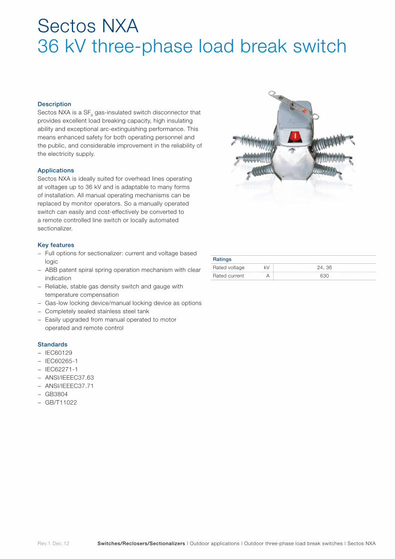
Rev.1 Dec.12 Switches/Reclosers/Sectionalizers | Outdoor applications | Outdoor three-phase load break switches | Sectos NXA
DescriptionSectos NXA is a SF6 gas-insulated switch disconnector that provides excellent load breaking capacity, high insulating ability and exceptional arc-extinguishing performance. This means enhanced safety for both operating personnel and the public, and considerable improvement in the reliability of the electricity supply.
ApplicationsSectos NXA is ideally suited for overhead lines operating at voltages up to 36 kV and is adaptable to many forms of installation. All manual operating mechanisms can be replaced by monitor operators. So a manually operated switch can easily and cost-effectively be converted to a remote controlled line switch or locally automated sectionalizer.
Key features − Full options for sectionalizer: current and voltage based
logic − ABB patent spiral spring operation mechanism with clear
indication − Reliable, stable gas density switch and gauge with
temperature compensation − Gas-low locking device/manual locking device as options − Completely sealed stainless steel tank − Easily upgraded from manual operated to motor
operated and remote control
Standards − IEC60129 − IEC60265-1 − IEC62271-1 − ANSI/IEEEC37.63 − ANSI/IEEEC37.71 − GB3804 − GB/T11022
Sectos NXA 36 kV three-phase load break switch
Ratings
Rated voltage kV 24, 36
Rated current A 630
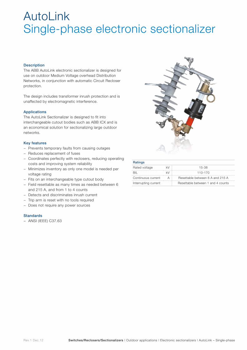
Rev.1 Dec.12 Switches/Reclosers/Sectionalizers | Outdoor applications | Electronic sectionalizers | AutoLink – Single-phase
DescriptionThe ABB AutoLink electronic sectionalizer is designed for use on outdoor Medium Voltage overhead Distribution Networks, in conjunction with automatic Circuit Recloser protection.
The design includes transformer inrush protection and is unaffected by electromagnetic interference.
ApplicationsThe AutoLink Sectionalizer is designed to fit into interchangeable cutout bodies such as ABB ICX and is an economical solution for sectionalizing large outdoor networks.
Key features − Prevents temporary faults from causing outages − Reduces replacement of fuses − Coordinates perfectly with reclosers, reducing operating
costs and improving system reliability − Minimizes inventory as only one model is needed per
voltage rating − Fits on an interchangeable type cutout body − Field resettable as many times as needed between 6
and 215 A, and from 1 to 4 counts − Detects and discriminates inrush current − Trip arm is reset with no tools required − Does not require any power sources
Standards − ANSI (IEEE) C37.63
AutoLinkSingle-phase electronic sectionalizer
Ratings
Rated voltage kV 15-38
BIL kV 110-170
Continuous current A Resettable between 6 A and 215 A
Interrupting current Resettable between 1 and 4 counts

Rev.1 Dec.12 Switches/Reclosers/Sectionalizers | Outdoor applications | Electronic sectionalizers |AutoLink – Three-phase
DescriptionThe three-phase AutoLink sectionalizer is an economical solution to sectionalizing three-phase networks.
The trip arm can be restored with no tools, and no accessories are needed.
ApplicationsThe three-phase AutoLink can be installed in various locations in MV networks simply by setting the actuating current and number of counts in order to provide correct coordination.
Key features − Prevents temporary faults from causing outages − Automatic 3 phase opening for overhead line isolation
and protection − One simple pole mounting arrangement − Field resettable as many times as needed between 6
and 215 A, and from 1 to 4 counts − Visible isolation on the lines − High level of operating safety − Maintenance free − Does not require any power sources
Standards − ANSI (IEEE) C37.63
AutoLink Three-phase electronic sectionalizer
Ratings
Rated voltage kV 27
BIL kV 125-150
Continuous current A 6-215
Interrupting current 1-4
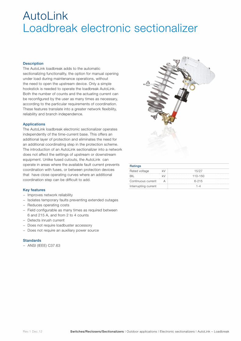
Rev.1 Dec.12 Switches/Reclosers/Sectionalizers | Outdoor applications | Electronic sectionalizers | AutoLink – Loadbreak
DescriptionThe AutoLink loadbreak adds to the automatic sectionalizing functionality, the option for manual opening under load during maintenance operations, without the need to open the upstream device. Only a simple hookstick is needed to operate the loadbreak AutoLink. Both the number of counts and the actuating current can be reconfigured by the user as many times as necessary, according to the particular requirements of coordination. These features translate into a greater network flexibility, reliability and branch independence.
ApplicationsThe AutoLink loadbreak electronic sectionalizer operates independently of the time-current base. This offers an additional layer of protection and eliminates the need for an additional coordinating step in the protection scheme. The introduction of an AutoLink sectionalizer into a network does not affect the settings of upstream or downstream equipment. Unlike fused cutouts, the AutoLink can operate in areas where the available fault current prevents coordination with fuses, or between protection devices that have close operating curves where an additional coordination step can be difficult to add.
Key features − Improves network reliability − Isolates temporary faults preventing extended outages − Reduces operating costs − Field configurable as many times as required between
6 and 215 A, and from 2 to 4 counts − Detects inrush current − Does not require loadbuster accessory − Does not require an auxiliary power source
Standards − ANSI (IEEE) C37.63
AutoLinkLoadbreak electronic sectionalizer
Ratings
Rated voltage kV 15/27
BIL kV 110-150
Continuous current A 6-215
Interrupting current 1-4
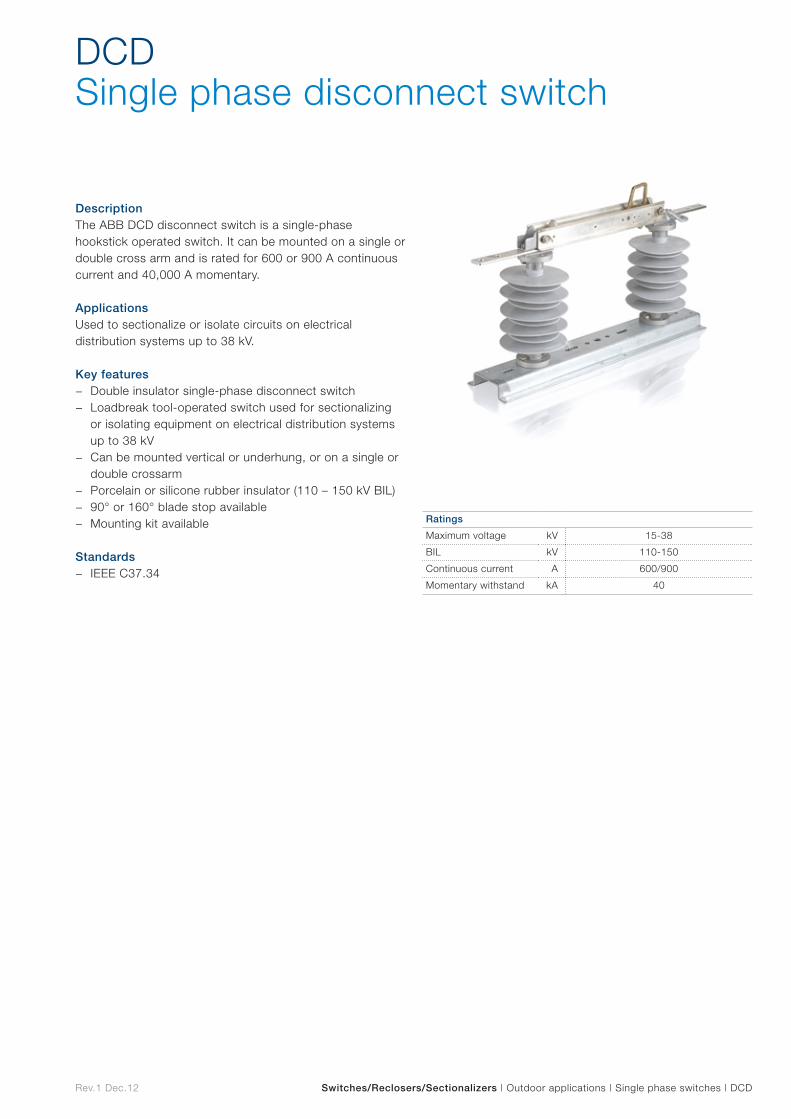
Rev.1 Dec.12 Switches/Reclosers/Sectionalizers | Outdoor applications | Single phase switches | DCD
DescriptionThe ABB DCD disconnect switch is a single-phase hookstick operated switch. It can be mounted on a single or double cross arm and is rated for 600 or 900 A continuous current and 40,000 A momentary.
ApplicationsUsed to sectionalize or isolate circuits on electrical distribution systems up to 38 kV.
Key features − Double insulator single-phase disconnect switch − Loadbreak tool-operated switch used for sectionalizing
or isolating equipment on electrical distribution systems up to 38 kV
− Can be mounted vertical or underhung, or on a single or double crossarm
− Porcelain or silicone rubber insulator (110 – 150 kV BIL) − 90° or 160° blade stop available − Mounting kit available
Standards − IEEE C37.34
DCDSingle phase disconnect switch
Ratings
Maximum voltage kV 15-38
BIL kV 110-150
Continuous current A 600/900
Momentary withstand kA 40
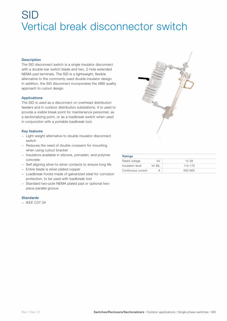
Rev.1 Dec.12 Switches/Reclosers/Sectionalizers | Outdoor applications | Single phase switches | SID
DescriptionThe SID disconnect switch is a single insulator disconnect with a double-bar switch blade and two, 2-hole extended NEMA pad terminals. The SID is a lightweight, flexible alternative to the commonly used double insulator design. In addition, the SID disconnect incorporates the ABB quality approach to cutout design.
ApplicationsThe SID is used as a disconnect on overhead distribution feeders and in outdoor distribution substations. It is used to provide a visible break point for maintenance personnel, as a sectionalizing point, or as a loadbreak switch when used in conjunction with a portable loadbreak tool.
Key features − Light weight alternative to double insulator disconnect
switch − Reduces the need of double crossarm for mounting
when using cutout bracket − Insulators available in silicone, porcelain, and polymer
concrete − Self aligning silver-to-silver contacts to ensure long life − Entire blade is silver-plated copper − Loadbreak hooks made of galvanized steel for corrosion
protection, to be used with loadbreak tool − Standard two-pole NEMA plated pad or optional two-
piece parallel groove
Standards − IEEE C37.34
SIDVertical break disconnector switch
Ratings
Rated voltage kV 15-38
Insulation level kV BIL 110-170
Continuous current A 600-900
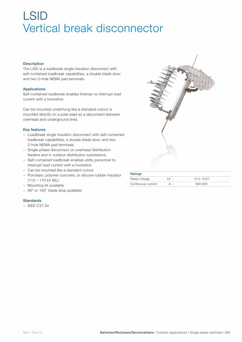
Rev.1 Dec.12 Switches/Reclosers/Sectionalizers | Outdoor applications | Single phase switches | SID
DescriptionThe LSID is a loadbreak single insulator disconnect with self-contained loadbreak capabilities, a double blade door, and two 2-hole NEMA pad terminals.
ApplicationsSelf-contained loadbreak enables lineman to interrupt load current with a hookstick.
Can be mounted underhung like a standard cutout or mounted directly on a pole used as a disconnect between overhead and underground lines.
Key features − Loadbreak single insulator disconnect with self-contained
loadbreak capabilities, a double blade door, and two 2-hole NEMA pad terminals
− Single-phase disconnect on overhead distribution feeders and in outdoor distribution substations
− Self-contained loadbreak enables utility personnel to interrupt load current with a hookstick
− Can be mounted like a standard cutout − Porcelain, polymer concrete, or silicone rubber insulator
(110 – 170 kV BIL) − Mounting kit available − 90° or 160° blade stop available
Standards − IEEE C37.34
LSIDVertical break disconnector
Ratings
Rated voltage kV 15.5-15/27
Continuous current A 600-900
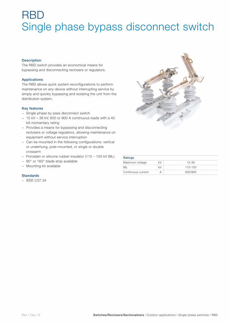
Rev.1 Dec.12 Switches/Reclosers/Sectionalizers | Outdoor applications | Single phase switches | RBD
DescriptionThe RBD switch provides an economical means for bypassing and disconnecting reclosers or regulators.
ApplicationsThe RBD allows quick system reconfigurations to perform maintenance on any device without interrupting service by simply and quickly bypassing and isolating the unit from the distribution system.
Key features − Single-phase by pass disconnect switch − 15 kV – 38 kV, 600 or 900 A continuous loads with a 40
kA momentary rating − Provides a means for bypassing and disconnecting
reclosers or voltage regulators, allowing maintenance on equipment without service interruption
− Can be mounted in the following configurations: vertical or underhung, pole-mounted, or single or double crossarm
− Porcelain or silicone rubber insulator (110 – 150 kV BIL) − 90° or 160° blade stop available − Mounting kit available
Standards − IEEE C37.34
RBD Single phase bypass disconnect switch
Ratings
Maximum voltage kV 15-38
BIL kV 110-150
Continuous current A 600/900
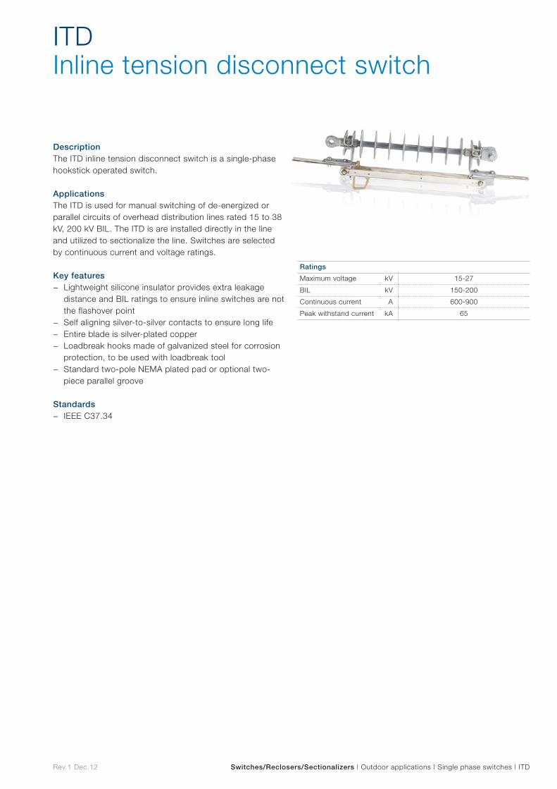
Rev.1 Dec.12 Switches/Reclosers/Sectionalizers | Outdoor applications | Single phase switches | ITD
DescriptionThe ITD inline tension disconnect switch is a single-phase hookstick operated switch.
ApplicationsThe ITD is used for manual switching of de-energized or parallel circuits of overhead distribution lines rated 15 to 38 kV, 200 kV BIL. The ITD is are installed directly in the line and utilized to sectionalize the line. Switches are selected by continuous current and voltage ratings.
Key features − Lightweight silicone insulator provides extra leakage
distance and BIL ratings to ensure inline switches are not the flashover point
− Self aligning silver-to-silver contacts to ensure long life − Entire blade is silver-plated copper − Loadbreak hooks made of galvanized steel for corrosion
protection, to be used with loadbreak tool − Standard two-pole NEMA plated pad or optional two-
piece parallel groove
Standards − IEEE C37.34
ITD Inline tension disconnect switch
Ratings
Maximum voltage kV 15-27
BIL kV 150-200
Continuous current A 600-900
Peak withstand current kA 65

Transformers
Transform
ers
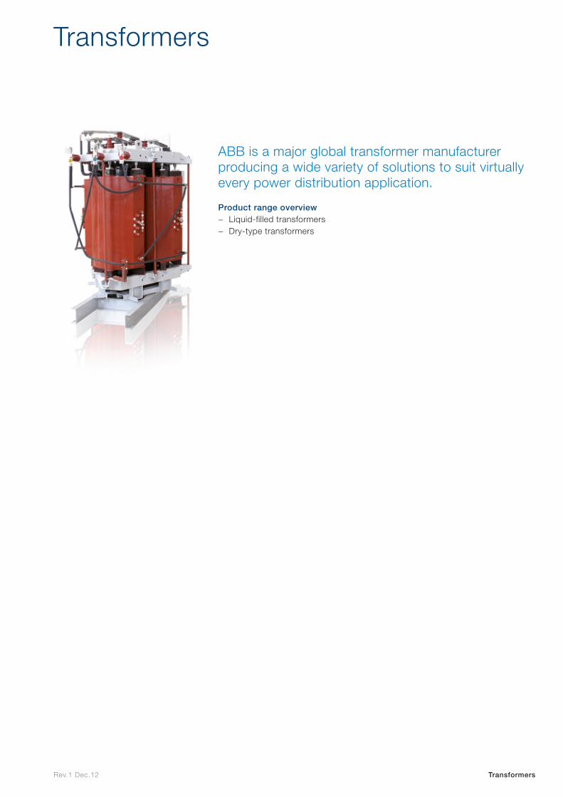
Rev.1 Dec.12 Transformers
ABB is a major global transformer manufacturer producing a wide variety of solutions to suit virtually every power distribution application.
Product range overview − Liquid-filled transformers − Dry-type transformers
Transformers

Liquid-filled
Liquid
-filled
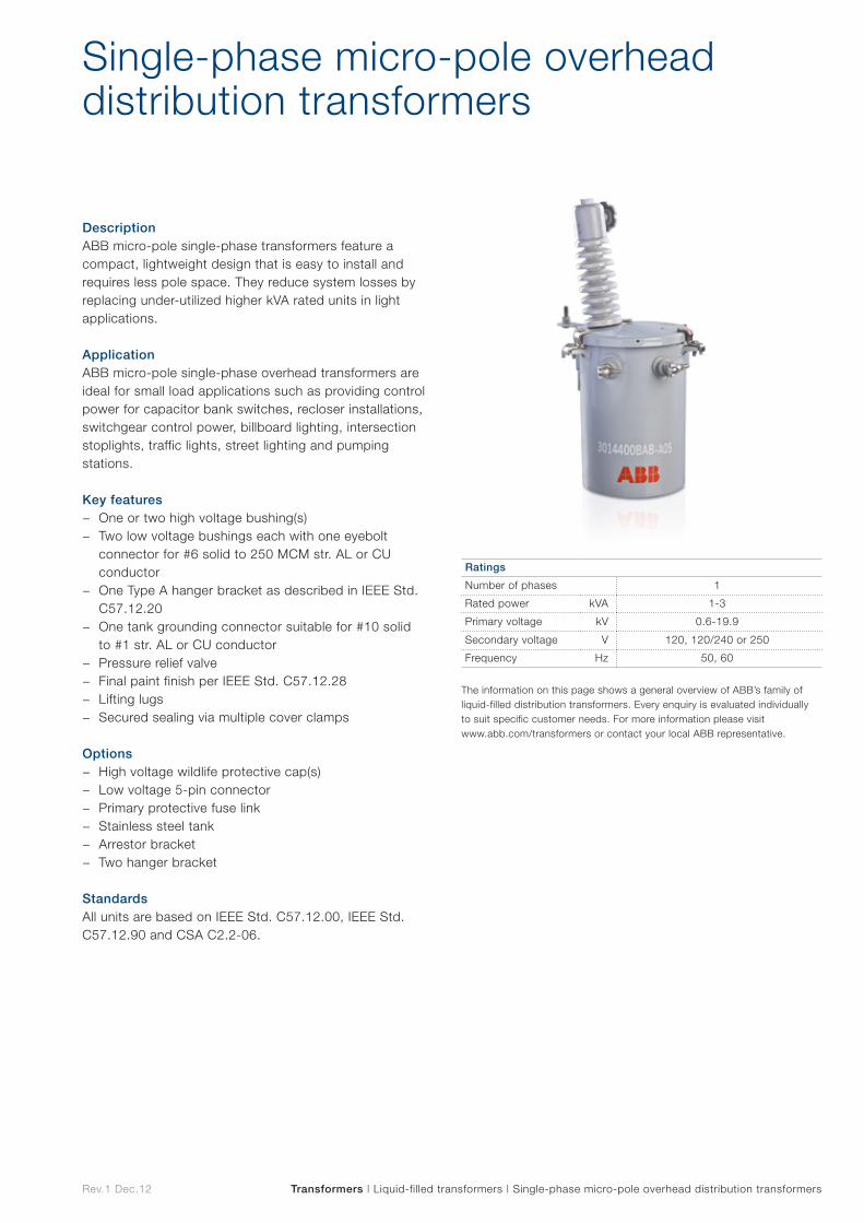
The information on this page shows a general overview of ABB’s family of liquid-filled distribution transformers. Every enquiry is evaluated individually to suit specific customer needs. For more information please visit www.abb.com/transformers or contact your local ABB representative.
Rev.1 Dec.12 Transformers | Liquid-filled transformers | Single-phase micro-pole overhead distribution transformers
DescriptionABB micro-pole single-phase transformers feature a compact, lightweight design that is easy to install and requires less pole space. They reduce system losses by replacing under-utilized higher kVA rated units in light applications.
Application ABB micro-pole single-phase overhead transformers are ideal for small load applications such as providing control power for capacitor bank switches, recloser installations, switchgear control power, billboard lighting, intersection stoplights, traffic lights, street lighting and pumping stations.
Key features − One or two high voltage bushing(s) − Two low voltage bushings each with one eyebolt
connector for #6 solid to 250 MCM str. AL or CU conductor
− One Type A hanger bracket as described in IEEE Std. C57.12.20
− One tank grounding connector suitable for #10 solid to #1 str. AL or CU conductor
− Pressure relief valve − Final paint finish per IEEE Std. C57.12.28 − Lifting lugs − Secured sealing via multiple cover clamps
Options
− High voltage wildlife protective cap(s) − Low voltage 5-pin connector − Primary protective fuse link − Stainless steel tank − Arrestor bracket − Two hanger bracket
StandardsAll units are based on IEEE Std. C57.12.00, IEEE Std. C57.12.90 and CSA C2.2-06.
Single-phase micro-pole overhead distribution transformers
Ratings
Number of phases 1
Rated power kVA 1-3
Primary voltage kV 0.6-19.9
Secondary voltage V 120, 120/240 or 250
Frequency Hz 50, 60

Rev.1 Dec.12 Transformers | Liquid-filled transformers | Single-phase overhead distribution transformers
DescriptionABB overhead transformers may be used on their own to supply a single-phase load or in a bank of three units for three-phase applications.
Application ABB overhead transformers are designed to support residential distribution loads. They are also suitable for light commercial loads, industrial lighting and diverse power applications.
Key features − Core and coils designed for an optimum total cost of
ownership (TCO) − Wound core with step-lap joints for increased efficiency
and lower noise levels − “Low-high-low” windings for increased short circuit
strength, efficiency and thermal strength − Computer aided design for mechanical and electrical
calculations (CAD) − Dual voltage designed to meet BIL and short circuit
requirements on both connections − Low voltage leads with embossed markings on all units
with 3 LV bushings for easy reading and permanent identification on selected ratings
− Paint system meeting or exceeding the performance of the IEEE C57.12.28 Standard (para. 5.3 to 5.5 included), including the salt spray test
− Lifting lugs − Multiple cover clamps to ensure proper sealing and to
minimize water retention on the cover edge − Cover or sidewall mounted high voltage bushing(s) as
required − Low voltage spade or clamp type (basket) terminals as
required − Provision for surge arrester bracket (bracket available as
an option) − Automatic self-resealing pressure relief valve
Options − Four HV winding taps complete with externally operated
tap switch − Dual voltage primary complete with externally operated
voltage switch − Extra creep bushing − Surge arrester bracket − Internal Fault Detector (IFD) − Non conductive transformer cover − Synthetic and natural ester fluids − Stainless steel tank and cover
StandardsAll units are based on IEEE Std. C57.12.00, IEEE Std. C57.12.90 and CSA C2.2-06.
Single-phase overhead distribution transformers
Ratings
Number of phases 1
Rated power kVA 10-167
Primary voltage kV 2.4-34.5
Secondary voltage V 120-600
Frequency Hz 50, 60
The information on this page shows a general overview of ABB’s family of liquid-filled distribution transformers. Every enquiry is evaluated individually to suit specific customer needs. For more information please visit www.abb.com/transformers or contact your local ABB representative.
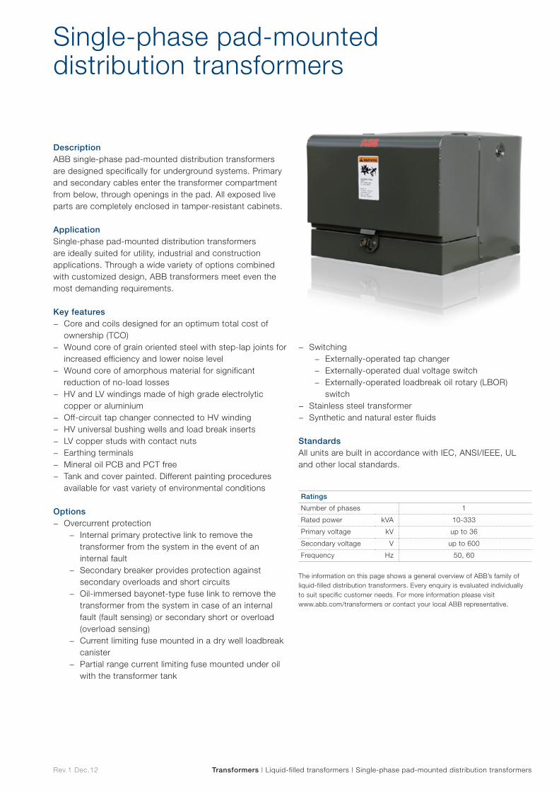
Rev.1 Dec.12
DescriptionABB single-phase pad-mounted distribution transformers are designed specifically for underground systems. Primary and secondary cables enter the transformer compartment from below, through openings in the pad. All exposed live parts are completely enclosed in tamper-resistant cabinets.
ApplicationSingle-phase pad-mounted distribution transformers are ideally suited for utility, industrial and construction applications. Through a wide variety of options combined with customized design, ABB transformers meet even the most demanding requirements.
Key features − Core and coils designed for an optimum total cost of
ownership (TCO) − Wound core of grain oriented steel with step-lap joints for
increased efficiency and lower noise level − Wound core of amorphous material for significant
reduction of no-load losses − HV and LV windings made of high grade electrolytic
copper or aluminium − Off-circuit tap changer connected to HV winding − HV universal bushing wells and load break inserts − LV copper studs with contact nuts − Earthing terminals − Mineral oil PCB and PCT free − Tank and cover painted. Different painting procedures
available for vast variety of environmental conditions Options
− Overcurrent protection − Internal primary protective link to remove the
transformer from the system in the event of an internal fault
− Secondary breaker provides protection against secondary overloads and short circuits
− Oil-immersed bayonet-type fuse link to remove the transformer from the system in case of an internal fault (fault sensing) or secondary short or overload (overload sensing)
− Current limiting fuse mounted in a dry well loadbreak canister
− Partial range current limiting fuse mounted under oil with the transformer tank
Single-phase pad-mounted distribution transformers
Transformers | Liquid-filled transformers | Single-phase pad-mounted distribution transformers
− Switching − Externally-operated tap changer − Externally-operated dual voltage switch − Externally-operated loadbreak oil rotary (LBOR)
switch − Stainless steel transformer − Synthetic and natural ester fluids
StandardsAll units are built in accordance with IEC, ANSI/IEEE, UL and other local standards.
Ratings
Number of phases 1
Rated power kVA 10-333
Primary voltage kV up to 36
Secondary voltage V up to 600
Frequency Hz 50, 60
The information on this page shows a general overview of ABB’s family of liquid-filled distribution transformers. Every enquiry is evaluated individually to suit specific customer needs. For more information please visit www.abb.com/transformers or contact your local ABB representative.
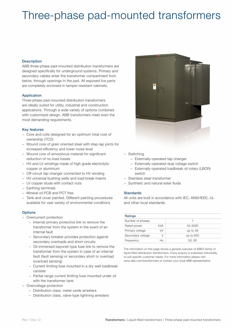
Rev.1 Dec.12
DescriptionABB three-phase pad-mounted distribution transformers are designed specifically for underground systems. Primary and secondary cables enter the transformer compartment from below, through openings in the pad. All exposed live parts are completely enclosed in tamper-resistant cabinets.
ApplicationThree-phase pad-mounted distribution transformers are ideally suited for utility, industrial and construction applications. Through a wide variety of options combined with customized design, ABB transformers meet even the most demanding requirements.
Key features − Core and coils designed for an optimum total cost of
ownership (TCO) − Wound core of grain oriented steel with step-lap joints for
increased efficiency and lower noise level − Wound core of amorphous material for significant
reduction of no-load losses − HV and LV windings made of high grade electrolytic
copper or aluminium − Off-circuit tap changer connected to HV winding − HV universal bushing wells and load break inserts − LV copper studs with contact nuts − Earthing terminals − Mineral oil PCB and PCT free − Tank and cover painted. Different painting procedures
available for vast variety of environmental conditions Options
− Overcurrent protection − Internal primary protective link to remove the
transformer from the system in the event of an internal fault
− Secondary breaker provides protection against secondary overloads and short circuits
− Oil-immersed bayonet-type fuse link to remove the transformer from the system in case of an internal fault (fault sensing) or secondary short or overload (overload sensing)
− Current limiting fuse mounted in a dry well loadbreak canister
− Partial range current limiting fuse mounted under oil with the transformer tank
− Overvoltage protection − Distribution class, metal oxide arresters − Distribution class, valve-type lightning arresters
− Switching − Externally-operated tap changer − Externally-operated dual voltage switch − Externally-operated loadbreak oil rotary (LBOR)
switch − Stainless steel transformer − Synthetic and natural ester fluids
StandardsAll units are built in accordance with IEC, ANSI/IEEE, UL and other local standards.
Three-phase pad-mounted transformers
Transformers | Liquid-filled transformers | Three-phase pad-mounted transformers
Ratings
Number of phases 1
Rated power kVA 45-3000
Primary voltage kV up to 36
Secondary voltage V up to 600
Frequency Hz 50, 60
The information on this page shows a general overview of ABB’s family of liquid-filled distribution transformers. Every enquiry is evaluated individually to suit specific customer needs. For more information please visit www.abb.com/transformers or contact your local ABB representative.
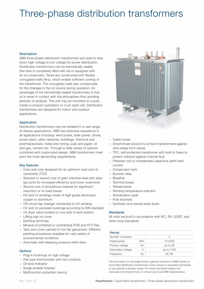
Rev.1 Dec.12 Transformers | Liquid-filled transformers | Three-phase distribution transformers
DescriptionABB three-phase distribution transformers are used to step down high voltage to low voltage for power distribution. Distribution transformers can be hermetically sealed (the tank is completely filled with oil) or equipped with an oil conservator. Tanks are constructed with flexible corrugated walls (fins), which enable sufficient cooling of the transformer. The corrugated walls also compensate for the changes in the oil volume during operation. An advantage of the hermetically sealed transformers is that oil is never in contact with the atmosphere thus avoiding periodic oil analysis. The unit may be mounted on a pole, inside a compact substation or in an open cell. Distribution transformers are designed for indoor and outdoor applications.
ApplicationDistribution transformers may be installed in a vast range of diverse applications. ABB has extensive experience in all applications including: wind power, solar power, drives, power plant, utility networks, buildings, chemical and pharmaceuticals, metal and mining, pulp and paper, oil and gas, cement etc. Through a wide variety of options combined with customized design, ABB transformers meet even the most demanding requirements.
Key features − Core and coils designed for an optimum total cost of
ownership (TCO) − Stacked or wound core of grain oriented steel with step-
lap joints for increased efficiency and lower noise level − Wound core of amorphous material for significant
reduction of no-load losses − HV and LV windings made of high grade electrolytic
copper or aluminium − Off-circuit tap changer connected to HV winding − HV and LV porcelain bushings according to DIN standard − Oil drain valve located on one side of tank bottom − Lifting lugs on cover − Earthing terminals − Mineral oil (inhibited or uninhibited) PCB and PCT free − Tank and cover painted or hot dip galvanized. Different
painting procedures available for vast variety of environmental conditions
− Automatic self-releasing pressure relief valve Options
− Plug-in bushings on high voltage − Dial type thermometer with two contacts − Oil level indicator − Surge arrester bracket − Multifunction protection device
− Cable boxes − Smartchoak-solution to protect transformers against
ultra-steep front waves − TPC, self-protected transformer with built-in fuses to
protect network against internal fault − Petersen coil to compensate capacitive earth fault
current − Conservator tank − Bucholz relay − Breather − Terminal boxes − Wheels/skids − Winding temperature indicator − Antivibration pads − Pole brackets − Synthetic and natural ester fluids
StandardsAll units are built in accordance with IEC, EN, GOST, and other local standards.
Three-phase distribution transformers
Ratings
Number of phases 3
Rated power kVA 10-2500
Primary voltage kV up to 36
Secondary voltage V up to 1100
Frequency Hz 50, 60
The information on this page shows a general overview of ABB’s family of liquid-filled distribution transformers. Every enquiry is evaluated individually to suit specific customer needs. For more information please visit www.abb.com/transformers or contact your local ABB representative.

Dry-type Dry-typ
e
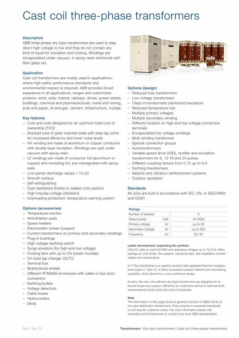
Rev.1 Dec.12
DescriptionABB three-phase dry-type transformers are used to step down high voltage to low and they do not contain any kind of liquid for insulation and cooling. Windings are encapsulated under vacuum, in epoxy resin reinforced with fiber glass net.
ApplicationCast coil transformers are mostly used in applications, where high safety performance standards and environmental respect is required. ABB provides broad experience in all applications, ranges and customized projects: wind, solar, marine, railways, drives, power plants, buildings, chemical and pharmaceuticals, metal and mining, pulp and paper, oil and gas, cement, infrastructure, nuclear.
Key features − Core and coils designed for an optimum total cost of
ownership (TCO) − Stacked core of grain oriented steel with step-lap joints
for increased efficiency and lower noise levels − HV winding are made of aluminium or copper conductor
with double layer insulation. Windings are cast under vacuum with epoxy resin
− LV windings are made of conductor foil (aluminium or copper) and insulating foil, pre-impregnated with epoxy resin
− Low partial discharge values < 10 pC − Smooth surface − Self extinguishing − Dust resistance thanks to sealed coils (option) − High impulse voltage withstand − Overloading protection: temperature warning system
Options (accessories) − Temperature monitor − Antivibtation pads − Space heaters − Electrostatic screen (copper) − Current transformers on primary and secondary windings − Plug-in bushings − High voltage earthing switch − Surge arrestors (for high and low voltage) − Cooling fans with up to 5% power increase − On-load tap changer (OLTC) − Terminal box − Bidirectional wheels − Different IP/NEMA enclosures with cable or bus-duct
connection − Earthing bullets − Voltage detectors − Cable boxes − Hydrocoolers − Skids
Options (design) − Reduced loss transformers − Low voltage transformers − Class H transformers (reinforced insulation) − Reduced temperature rise − Multiple primary voltages − Multiple secondary winding − Different location on high and low voltage connection
terminals − Encapsulated low voltage windings − Multi winding transformer − Special connection groups − Autotransformers − Variable speed drive (VSD), rectifier and excitation
transformers for 6, 12 18 and 24 pulses − Different coupling factors from 0,15 up to 0,9 − Earthing transformers − Seismic and vibration reinforcement systems − Outdoor operation
StandardsAll units are built in accordance with IEC, EN, or IEEE/ANSI and GOST.
Cast coil three-phase transformers
Transformers | Dry-type transformers | Cast coil three-phase transformers
Ratings
Number of phases 3
Rated power kVA 45-3000
Primary voltage kV up to 36
Secondary voltage kV up to 600
Frequency Hz 50, 60
Latest development: expanding the portfolioHiDry72, able to reach 63 MVA and operating voltages up to 72,5 kV, offers savings on: civil works, fire systems, insurance fees, site installation, shorter cables and maintenance.
hi-T Plus transformer is a superior product with upgraded thermal insulation level (class H: 180o C). It offers increased insulation lifetime and overloading capability, which allows for a more optimized design.
EcoDry: the new ultra efficient dry-type transformers are designed for re-duced losses and superior efficiency for customers aiming to optimise both environmental impact and total cost of ownership.
NoteThe information on this page shows a general overview of ABB’s family of dry-type distribution transformers. Every enquiry is evaluated individually to suit specific customer needs. For more information please visit www.abb.com/transformers or contact your local ABB representative.
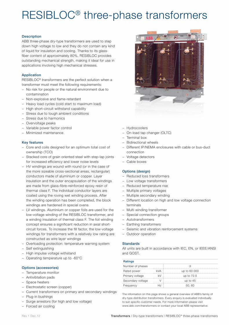
Rev.1 Dec.12
DescriptionABB three-phase dry-type transformers are used to step down high voltage to low and they do not contain any kind of liquid for insulation and cooling. Thanks to its glass-fiber content of approximately 80%, RESIBLOC provides outstanding mechanical strength, making it ideal for use in applications involving high mechanical stresses.
ApplicationRESIBLOC® transformers are the perfect solution when a transformer must meet the following requirements:
− No risk for people or the natural environment due to contamination
− Non-explosive and flame-retardant − Heavy load cycles (cold start to maximum load) − High short-circuit withstand capability − Stress due to tough ambient conditions − Stress due to harmonics − Overvoltage peaks − Variable power factor control − Minimized maintenance
Key features
− Core and coils designed for an optimum total cost of ownership (TCO)
− Stacked core of grain oriented steel with step-lap joints for increased efficiency and lower noise levels
− HV windings are wound with round (or in the case of the more sizeable cross-sectional areas, rectangular) conductors made of aluminium or copper. Layer insulation and the outer encapsulation of the windings are made from glass-fibre-reinforced epoxy resin of thermal class F. The individual conductor layers are coated using the roving wet winding process. After the winding operation has been completed, the block windings are hardened in special ovens
− LV windings. Aluminium or copper foils are used for the low-voltage winding of the RESIBLOC transformer, and a winding insulation of thermal class F. The foil winding concept ensures a significant reduction in axial short-circuit forces. To increase the fill factor, the low-voltage windings for transformers with a relatively low rating are constructed as wire layer windings
− Overloading protection: temperature warning system − Self extinguishing − High impulse voltage withstand − Operating temperature up to -60°C
Options (accessories) − Temperature monitor − Antivibtation pads − Space heaters − Electrostatic screen (copper) − Current transformers on primary and secondary windings − Plug-in bushings − Surge arrestors (for high and low voltage) − Forced air cooling
RESIBLOC® three-phase transformers
Transformers | Dry-type transformers | RESIBLOC® three-phase transformers
− Hydrocoolers − On-load tap changer (OLTC) − Terminal box − Bidirectional wheels − Different IP/NEMA enclosures with cable or bus-duct
connection − Voltage detectors − Cable boxes
Options (design) − Reduced loss transformers − Low voltage transformers − Reduced temperature rise − Multiple primary voltages − Multiple secondary winding − Different location on high and low voltage connection
terminals − Multi winding transformer − Special connection groups − Autotransformers − Earthing transformers − Seismic and vibration reinforcement systems − Outdoor operation
StandardsAll units are built in accordance with IEC, EN, or IEEE/ANSI and GOST.
Ratings
Number of phases 3
Rated power kVA up to 60 000
Primary voltage kV up to 72.5
Secondary voltage V up to 45
Frequency Hz 50, 60
The information on this page shows a general overview of ABB’s family of dry-type distribution transformers. Every enquiry is evaluated individually to suit specific customer needs. For more information please visit www.abb.com/transformers or contact your local ABB representative.
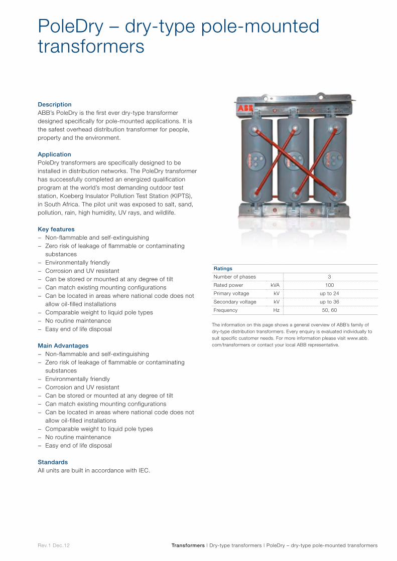
Rev.1 Dec.12
DescriptionABB’s PoleDry is the first ever dry-type transformer designed specifically for pole-mounted applications. It is the safest overhead distribution transformer for people, property and the environment.
ApplicationPoleDry transformers are specifically designed to be installed in distribution networks. The PoleDry transformer has successfully completed an energized qualification program at the world’s most demanding outdoor test station, Koeberg Insulator Pollution Test Station (KIPTS), in South Africa. The pilot unit was exposed to salt, sand, pollution, rain, high humidity, UV rays, and wildlife.
Key features − Non-flammable and self-extinguishing − Zero risk of leakage of flammable or contaminating
substances − Environmentally friendly − Corrosion and UV resistant − Can be stored or mounted at any degree of tilt − Can match existing mounting configurations − Can be located in areas where national code does not
allow oil-filled installations − Comparable weight to liquid pole types − No routine maintenance − Easy end of life disposal
Main Advantages − Non-flammable and self-extinguishing − Zero risk of leakage of flammable or contaminating
substances − Environmentally friendly − Corrosion and UV resistant − Can be stored or mounted at any degree of tilt − Can match existing mounting configurations − Can be located in areas where national code does not
allow oil-filled installations − Comparable weight to liquid pole types − No routine maintenance − Easy end of life disposal
StandardsAll units are built in accordance with IEC.
PoleDry – dry-type pole-mounted transformers
Transformers | Dry-type transformers | PoleDry – dry-type pole-mounted transformers
Ratings
Number of phases 3
Rated power kVA 100
Primary voltage kV up to 24
Secondary voltage kV up to 36
Frequency Hz 50, 60
The information on this page shows a general overview of ABB’s family of dry-type distribution transformers. Every enquiry is evaluated individually to suit specific customer needs. For more information please visit www.abb.com/transformers or contact your local ABB representative.
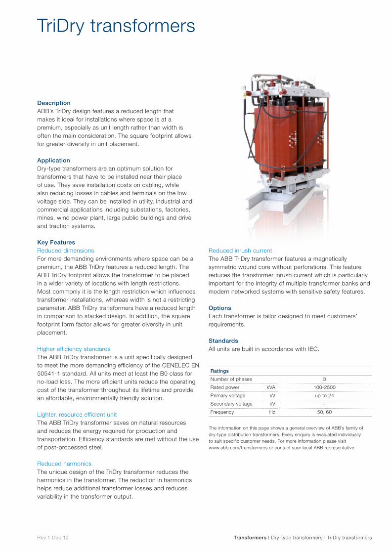
Rev.1 Dec.12
DescriptionABB’s TriDry design features a reduced length that makes it ideal for installations where space is at a premium, especially as unit length rather than width is often the main consideration. The square footprint allows for greater diversity in unit placement.
ApplicationDry-type transformers are an optimum solution for transformers that have to be installed near their place of use. They save installation costs on cabling, while also reducing losses in cables and terminals on the low voltage side. They can be installed in utility, industrial and commercial applications including substations, factories, mines, wind power plant, large public buildings and drive and traction systems.
Key FeaturesReduced dimensionsFor more demanding environments where space can be a premium, the ABB TriDry features a reduced length. The ABB TriDry footprint allows the transformer to be placed in a wider variety of locations with length restrictions. Most commonly it is the length restriction which influences transformer installations, whereas width is not a restricting parameter. ABB TriDry transformers have a reduced length in comparison to stacked design. In addition, the square footprint form factor allows for greater diversity in unit placement.
Higher efficiency standardsThe ABB TriDry transformer is a unit specifically designed to meet the more demanding efficiency of the CENELEC EN 50541-1 standard. All units meet at least the B0 class for no-load loss. The more efficient units reduce the operating cost of the transformer throughout its lifetime and provide an affordable, environmentally friendly solution.
Lighter, resource efficient unit The ABB TriDry transformer saves on natural resources and reduces the energy required for production and transportation. Efficiency standards are met without the use of post-processed steel.
Reduced harmonics The unique design of the TriDry transformer reduces the harmonics in the transformer. The reduction in harmonics helps reduce additional transformer losses and reduces variability in the transformer output.
Reduced inrush current The ABB TriDry transformer features a magnetically symmetric wound core without perforations. This feature reduces the transformer inrush current which is particularly important for the integrity of multiple transformer banks and modern networked systems with sensitive safety features.
OptionsEach transformer is tailor designed to meet customers’ requirements.
StandardsAll units are built in accordance with IEC.
TriDry transformers
Transformers | Dry-type transformers | TriDry transformers
Ratings
Number of phases 3
Rated power kVA 100-2500
Primary voltage kV up to 24
Secondary voltage kV –
Frequency Hz 50, 60
The information on this page shows a general overview of ABB’s family of dry-type distribution transformers. Every enquiry is evaluated individually to suit specific customer needs. For more information please visit www.abb.com/transformers or contact your local ABB representative.
Vacuum interrupters and poles
Vacuum
interrupters
and p
oles
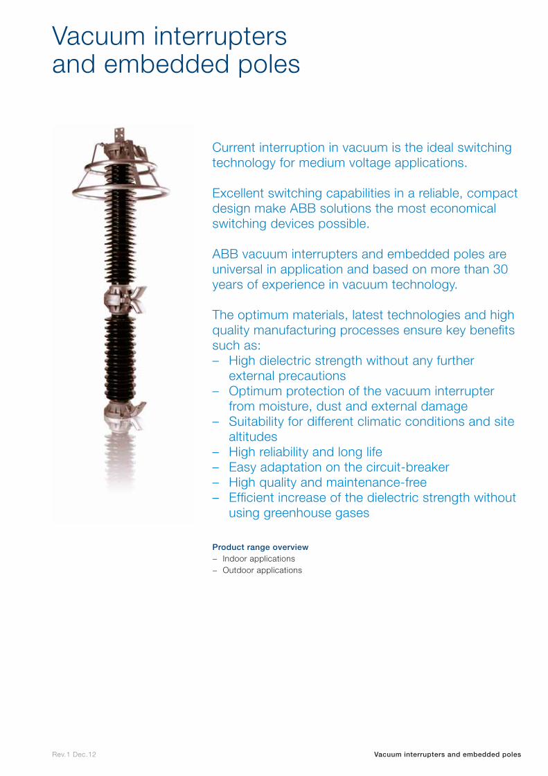
Rev.1 Dec.12 Vacuum interrupters and embedded poles
Current interruption in vacuum is the ideal switching technology for medium voltage applications.
Excellent switching capabilities in a reliable, compact design make ABB solutions the most economical switching devices possible.
ABB vacuum interrupters and embedded poles are universal in application and based on more than 30 years of experience in vacuum technology.
The optimum materials, latest technologies and high quality manufacturing processes ensure key benefits such as: – High dielectric strength without any further
external precautions – Optimum protection of the vacuum interrupter
from moisture, dust and external damage – Suitability for different climatic conditions and site
altitudes – High reliability and long life – Easy adaptation on the circuit-breaker – High quality and maintenance-free – Efficient increase of the dielectric strength without
using greenhouse gases
Product range overview
− Indoor applications − Outdoor applications
Vacuum interrupters and embedded poles

Indoor applications
Indo
or
app
lications

Outdoor applications Outd
oo
r ap
plicatio
ns

Service
Service
Rev.1 Dec.12 Power Products Service
ABB’s comprehensive range of world class power products comes with unrivalled service support that covers every requirement from installation and commissioning to through-life preventive and corrective maintenance. This ensures that our customers always enjoy reliable and efficient operation over the entire product life cycle.
Power Products Service
Installation and commissioningInstallation and commissioning from individual products to complete systems.
DiagnosisInspection and analysis to improve operating efficiencies and extend asset life.
Environmental servicesPlant, equipment, PCB disposal, pollution prevention/ control, waste minimization.
Migration and upgradesServices and products to evolve or upgrade to the next generation of hardware and software.
RetrofitExchange of worn parts or outdated components while maintaining the original configuration or upgrading to higher performance levels
Support and remote servicesOn demand expert support for ABB equipment using telephone consultations, online knowledge management and remote equipment monitoring services.
Asset upgradeImproving the performance of existing equipment.
Safety servicesPersonnel risk prevention.
Engineering and consultingIdentification of opportunities and implementing solutions to improve performance, processes and compliance.
ExtensionExpansions and extensions to installed systems by adding new equipment or functionality.
Maintenance and field servicesPreventative, predictive and corrective services to maximize the performance, reliability and availability of equipment.
Repair and refurbishFactory approved repair, partial or complete reconditioning of products or systems.
Spare partsSpare parts, emergency support, repair and exchange, inventory management and logistics solutions.

Rev.1 Dec.12 Power Products Service | Your global service partner
Your global service partner
ABB is one of the world’s largest power transmission and distribution manufacturers offering a wide range of services which cover an extensive global installed base.
The best practices worldwide and more than 100 years of experience and innovation are incorporated in every delivery we make. We work in partnership with you to ensure that you get the very best service in the fastest possible time.
Expert global networkThrough ABB you can access more than 1,000 technical experts located around the world. Thanks to our global certification program, our extensive network of specialists provides consistent delivery to the highest service and safety standards. Our service teams are available 24/7 no matter where you are based – in any of the five continents – with ABB at your service you’ll always have peace of mind.
Full service portfolioWhatever your needs, we support our products with a full service portfolio that covers every network application, from large to small.
Each and every job, on or off-site, is accurately assessed, utilizing highly developed skills and technical tools to ensure the best outcome. Our solutions take all factors into consideration, including technical, financial, environmental and safety aspects. The result is a reliable and long lasting solution.
Life cycle supportABB has several long established global factories and a robust R&D infrastructure. Combined with our extensive network of local service centers this enables us to provide the very highest standards of product support from installation to end of life. It doesn’t matter how old your equipment is, with ABB there is always a solution.
Always one step aheadStaying ahead means taking the right decisions, at the right time, based on the right information. ABB Power Products aims to work as an active partner in your business. At all times we support our installed base through proactive service offerings that ensure high reliability and optimal performance of your power assets.

Others
Others
Rev
.3 F
eb.1
3
Contact us
Your sales contact: www.abb.com/contacts
More product information: www.abb.com/productguide