Infrared Hydrocarbon Gas Detector PointWatch Eclipse Model PIRECL
Upload
furqan-aijazCategory
view
73download
0
DETCON IR-700 HYDROCARBON GAS DETECTOR
Prepared By
Furqan Aijaz

SUMMARY OF TRAINING TOPICS
Introduction Principle Of Operation PROGRAMMING MAGNET INSTRUCTIONS OPERATOR INTERFACE SERVICE AND MAINTENANCE TROUBLESHOOTING GUIDE
IR-700
Detcon Model IR-700 combustible gas sensors are non-intrusive “Smart” sensors designed to detect and monitor combustible hydrocarbon gases in air. The range of detection is 0-100% LEL or 0-50% LEL.
The unit is equipped with standard analog 4-20mA and Modbus™ RS-485 outputs. A primary feature of the sensor is its method of automatic calibration, which guides the user through each step via fully scripted instructions shown on the LED display.

WORKING PRINCIPLE(NDIR)
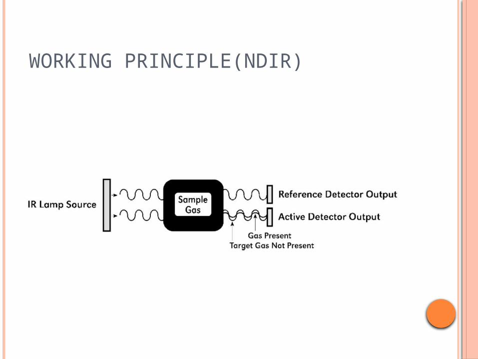
The target gas diffuses through a sintered stainless steel flame arrestor and into the volume of the sample gas optical chamber. An alternating miniature lamp provides a cyclical IR radiation source, which reflects through the optical gas sample chamber and terminates at two pyro electric detectors. The active and reference pyro electric detectors each give an output which measures the intensity of the radiation contacting their surface.
The active detector is covered by an optical filter specific to the part of the IR spectrum where the target gas absorbs light. The reference detector is covered by a filter specific to the non-absorbing part of the IR spectrum. When present, the target gas absorbs a fraction of the IR radiation and the signal output from the active detector decreases accordingly. The signal output of the reference detector remains unchanged in the presence of the target gas. The ratio of the active/reference signal outputs is then used to compute the target gas concentration. By using the ratio of the active/reference signal outputs, measurement drift caused by the changes in the intensity of the IR lamp source or changes in the optical path’s reflectivity is prevented
WORKING PRINCIPLE(NDIR)

PROGRAMMING MAGNET
The Operator Interface of the Model 700 Series gas sensors is accomplished via two internal magnetic switches located to either side of the LED display The two switches, labelled “PGM1” and “PGM2”, allow for complete calibration and configuration and thereby eliminate the need for area declassification or the use of hot permits.

The magnetic programming tool is used to operate the magnetic switches. Switch action is defined as:
Momentary contact, 3-second hold, and 10-second hold. (Hold times are defined as the time from the point when the arrow-prompt ““appears.) For momentary contact use, the programming magnet is briefly held over a switch location.
For 3-second hold, the programming magnet is held in place over the switch location for three seconds.
For 10-second hold, the programming magnet is held in place over the switch location for 10 seconds. The 3 and 10 second holds are generally used to enter calibration/program menus and save new data. The momentary contact is generally used to move between menu items and to modify set-point values.
Arrows are used on the LED display to indicate when the magnetic switches are activated.

OPERATOR INTERFACE
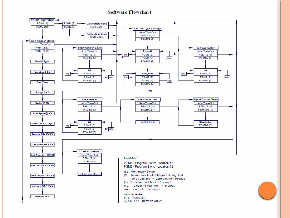
The operating interface is menu-driven via the two magnetic program switches located under the target marks of the sensor housing. The two switches are referred to as “PGM1” and “PGM2”. The menu list consists of three major items that include sub-menus
1. Normal Operation 2. Calibration Mode 3. Programming Mode
NORMAL &CALIBRATION MODE
Normal ModeCurrent Reading and Fault Status
Calibration Mode AutoZero AutoSpan

PROGRAM MODE 1. View Sensor Status2. Sensor Model Type 3. Current Software
Version4. Gas Type 5. Range of Detection 6. Serial ID address7. AutoSpan Level 8. Days From Last
AutoSpan 9. Remaining Sensor Life 10. Gas Factor 11. Raw Active Counts
12. Raw Reference Counts
13. 4-20mA Output 14. Input Voltage Supply15. Sensor Temperature 16. Set AutoSpan Level 17. Set Gas Type & Range 18. Set Gas Factor 19. Set Serial ID 20. Set Sensor Gain21. Signal Output Check 22. Restore Default
Settings
NORMAL OPERATION In normal operation, the ITM Display
continuously shows the current sensor reading, which will normally appear as “0”. Once every 60 seconds the LED display will flash the sensor’s measurement units and gas type (i.e. % LEL). If the sensor is actively experiencing any diagnostic faults, a “Fault Detected” message will flash on the ITM display once every minute. When the unit is in “Fault Detected” mode, PGM1 or PGM2 can be swiped to prompt the sensor to display the list of the active faults.
In normal operation, the 4-20mA current output corresponds with the present gas concentration and full-scale range.
CALIBRATION MODE
AUTOZERO
The AutoZero function is used to set the sensor’s zero baseline. Local ambient air can be used to zero calibrate the sensor as long as it can be confirmed that it contains no combustible hydrocarbon gases. If this cannot be confirmed then a zero air or pure N2 cylinder should be used.
From Normal Operation, enter Calibration Mode by holding the programming magnet over PGM1 for 3 seconds. Note, the prompt will show that the magnetic switch is activated during the 3 second hold period. The display will then scroll “PGM1=Zero …PGM2=Span”. Hold the programming magnet over PGM1 for 3 seconds once the prompt appears to execute AutoZero (or allow to timeout in 5 seconds if AutoZero is not desired).
CALIBRATION MODE The ITM will display the following sequence of
text messages as it proceeds through the AutoZero sequence:
Zero Cal. . .Setting Zero. . . Zero Saved (each will scroll twice)
Remove the zero gas and calibration adapter, if applicable.
Upon entering Calibration Mode, the 4-20mA signal drops to 2mA and is held at this level until the program returns to normal operation.
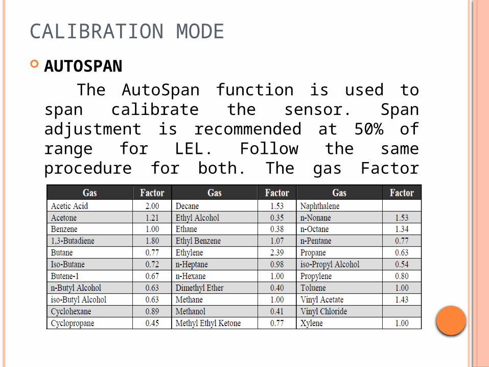
CALIBRATION MODE AUTOSPAN The AutoSpan function is used to span
calibrate the sensor. Span adjustment is recommended at 50% of range for LEL. Follow the same procedure for both. The gas Factor Table should be used for Methane and for Heavy Hydrocarbon gas.

CALIBRATION MODE(AUTOSPAN) AutoSpan consists of entering Calibration Mode
and following the menu-displayed instructions. The display will ask for the application of span gas in a specific concentration. This concentration must be equal to the calibration gas level setting. The factory default setting and recommendation for span gas concentration is 50% of the sensor’s range. If a span gas containing the recommended concentration is not available, other concentrations may be used as long as they fall between 5% and 95% of the sensor’s range. However, any alternate span gas concentration value must be programmed via the “Set AutoSpan Level” menu before proceeding with AutoSpan calibration. Follow the instructions “a” through “e” below for AutoSpan calibration:
CALIBRATION MODE(AUTOSPAN) Verify that the AutoSpan Level is equal to the
calibration span gas concentration. If the AutoSpan Level is not equal to the calibration span gas concentration, adjust the AutoSpan Level .
From Normal Operation, enter Calibration Mode by holding the programming magnet over PGM1 for 3 seconds. Note, the prompt will show that the magnetic switch is activated during the 3 second hold period. The display will then scroll “PGM1=Zero . . . PGM2=Span”. Hold the programming magnet over PGM2 for 3 seconds to execute AutoSpan (or allow to timeout in 5 seconds if AutoSpan is not intended).The ITM will then scroll “Apply XX %LEL Gas” (where XX is the AutoSpan Level).

CALIBRATION MODE(AUTOSPAN) Apply the span calibration test gas at a flow
rate of 200cc/min. As the sensor signal begins to increase the display will switch to reporting a flashing “XX” reading as the ITM shows the sensor’s “as found” response to the span gas presented. If it fails to meet the minimum in-range signal change criteria within 2½ minutes, the display will report “Range Fault” twice and the ITM will return to normal operation, aborting the AutoSpan sequence. The ITM will continue to report a “Range Fault” and will not clear the fault until a successful AutoSpan is completed. Assuming acceptable sensor signal change, after 1 minute the reading will auto-adjust to the programmed AutoSpan level.
CALIBRATION MODE(AUTOSPAN) During the next 30 seconds, the AutoSpan sequence
checks the sensor for acceptable reading stability. If the sensor fails the stability check, the reading is re-adjusted back to the AutoSpan level and the cycle repeats until the stability check is passed. Up to three additional 30-second stability check periods are allowed before the unit reports a “Stability Fault” twice and the ITM will return to normal operation, aborting the AutoSpan sequence. The ITM will continue to report a “Stability Fault” and will not clear the fault until a successful AutoSpan is completed. If the sensor passes the stability check, the ITM reports a series of messages:
“AutoSpanComplete” “Sensor Life XXX%”
“Remove Span Gas”

CALIBRATION MODE(AUTOSPAN) Remove the span gas and calibration
adapter. The ITM will report a live reading that alternates with “Remove Gas” message as it clears toward “0”. When the reading clears below 5 % LEL, the ITM will display “Span Complete” and will revert to normal operation. If the sensor fails to clear to less than 5 % LEL in less than 5 minutes, a “Clearing Fault” will be reported twice and the ITM will return to normal operation, aborting the AutoSpan sequence. The ITM will continue to report a “Clearing Fault” and will not clear the fault until a successful AutoSpan is completed
CALIBRATION MODE(AUTOSPAN) FAULTS If the sensor fails the minimum signal change
criteria, a “Range Fault” will be declared and a “Fault Detected” message will be displayed alternately with the sensor’s current reading. The 4-20 output will be taken to 0mA
If the sensor fails the stability criteria, a “Stability Fault” will be declared and a “Fault Detected” message will be displayed alternately with the sensor’s current reading. The 4-20mA output will be taken to 0mA.
If the sensor fails the clearing time criteria, a “Clearing Fault” will be declared and a “Fault Detected” message will be displayed alternately with the sensor’s current reading. The 4-20 output will be taken to 0mA