Scope - Kenexis Web viewPerform detector technology assessment to facilitate detector technology...
25
Model RFQ for Fire & Gas Mapping Version: 12 Sep 2016
Transcript of Scope - Kenexis Web viewPerform detector technology assessment to facilitate detector technology...

Model RFQ for Fire & Gas MappingVersion: 12 Sep 2016

Table of Contents1. Scope...................................................................................................................................................4
2. Terms and Abbreviations.....................................................................................................................4
2.1 Terms...........................................................................................................................................4
2.2 Abbreviations...............................................................................................................................4
3. Reference Documents.........................................................................................................................4
3.1 Reference Drawings.....................................................................................................................4
3.2 COMPANY Standards...................................................................................................................5
3.3 External Standards.......................................................................................................................5
3.4 Potential Document Conflicts or Errors.......................................................................................5
4. Study Objectives..................................................................................................................................5
5. Study Methodology.............................................................................................................................6
5.1 Fire and Gas Zone Definition........................................................................................................6
5.2 HAZID and FGS Function Development........................................................................................7
5.3 Analyze Risk and Define FGS Performance Targets......................................................................7
5.4 Design Basis Consequence Modeling...........................................................................................8
5.5 Detector Technology Assessment................................................................................................9
5.6 Fire and Gas Mapping for Coverage Verification.........................................................................9
5.7 FGS Function Safety Availability (SIL) Verification......................................................................11
5.7 FGS Requirements Specifications...............................................................................................11
5.8 FGS Verification and Validation.................................................................................................12
6. Study Deliverables.............................................................................................................................13
7. Project Schedule................................................................................................................................13
8. Meetings and Presentations..............................................................................................................13
9. Information to be Presented in the Proposal....................................................................................13
10. Basis of Commercial Proposal........................................................................................................14
Appendix A – Facility Description..............................................................................................................15
Appendix B – FGS Zone List and Zone Extents Drawing.............................................................................17
Appendix C – FGS Function List – Typical...................................................................................................20
Appendix D – FGS Performance Target List...............................................................................................22
KenexisMay 2023 CONFIDENTIAL INFORMATION Page 2

Appendix E – Design Basis Consequence Modeling Results......................................................................25
Appendix F – Typical Fire and Gas Mapping Results..................................................................................26
Appendix G – Typical FGS Requirements Specifications Components.......................................................30
KenexisMay 2023 CONFIDENTIAL INFORMATION Page 3

1. ScopeThis document defines the scope of work for Fire & Gas Mapping to be performed for the facilities described in Appendix A – Facility Description.
2. Terms and Abbreviations
2.1 TermsCOMPANY (Name of Operating Company)
ENGINEER (Name of Engineering Company, if subcontracted through third party)
CONSULTANT Entity contracted by COMPANY or ENGINEER to perform the scope of services contained in this document
SCOPE OF WORK The work required to complete the Performance-Based Fire and Gas Detection and Suppression System Design Basis, as detailed in this document, for the facilities described in Appendix A – Facility Description
2.2 AbbreviationsF&G Fire and Gas
FGS Fire and Gas System
FM Factory Mutual
3. Reference DocumentsThe project documentation, codes, standards, and other documents that define the scope of this project and the limitations and expectations under which the project is to be executed are listed in the following sections.
3.1 Reference DrawingsDrawing Number Title
Process Flow DiagramsPiping and Instrumentation Diagrams
3.2 COMPANY StandardsDocument Number Title
Fire & Gas System Philosophy
KenexisMay 2023 CONFIDENTIAL INFORMATION Page 4

3.3 External StandardsDocument Number TitleISA TR 84.00.07 Guidance on the Evaluation of Fire and Gas System
EffectivenessIEC 61511 Functional safety: Safety Instrumented Systems for
the process industry sector
3.4 Potential Document Conflicts or ErrorsThe documents that are referenced in Section 3 of this document are incorporated by reference into this request for proposal document. If any errors of conflicts are found to occur within this proposal document or the incorporated reference documents, the conflicts shall be brought to the attention of ENGINEER or COMPANY for resolution.
4. Study ObjectivesThe primary objective of this study is to develop a design-basis for the implementation of a fire and gas detection system. At the conclusion of the study the facility, as described in Appendix A – Facility Description, shall be completely defined in terms of detector layout. The study shall include the following, tasks with associated deliverable documents:
Definition of Major Equipment, Process Streams, and Hazards Analyze Risk and Define FGS Performance Targets, including:
o Classify each zoneo Grade all zones classified as a process areao Develop zone extents diagrams (where applicableo Assign detector coverage targets (where applicable)o Assign FGS function safety availability (SIL) target (where applicable)
Perform Design Basis Consequence Modeling Perform detector technology assessment to facilitate detector technology selection Perform Fire and Gas Mapping to verify that the proposed detector layout achieves coverage
performance targets
5. Study MethodologyThe study shall be performed in accordance with the methodologies and constraints specified in the following sections.
5.1 Definition of Major Equipment, Process Streams, and HazardsCONSULTANT shall review the scope of facilities of this project (as defined in Appendix A – Facility Description) in order identify the major equipment items, identify the hazardous process streams associated with this equipment, and classify the hazards associated with those process streams. This includes identifying the typical process material(s), normal operating conditions, and whether the
KenexisMay 2023 CONFIDENTIAL INFORMATION Page 5

materials processed contain hydrocarbon fire hazards, combustible gas hazards, or toxic gas hazards. Major equipment items to be listed include storage tanks, pressure vessels, pumps, compressors, separation equipment, heat exchangers, wellheads, manifolds, etc.
Once streams have been assigned to each equipment item, the hazards will be listed for each major piece of equipment. The outcome of a hazard depends on the process fluid composition (representative stream), the process conditions (temperature and pressure), the size and duration of the release, and the type and location of ignition sources.
The result of this task is a preliminary equipment item list (with associated stream and hazard classifications).
5.3 Analyze Risk and Define FGS Performance TargetsCONSULTANT shall conduct and document a risk analysis where the appropriate performance targets for each FGS function are defined. The risk analysis and associated documentation shall be performed in accordance with COMPANY procedures for performance based fire and gas system design. Each zone is assigned a category to determine performance requirements for fire and gas detection, which includes targets for detector coverage. Each FGS function with a hydrocarbon zone shall be assigned a safety availability (SIL) target. The analysis shall be based on risk of safety and/or commercial impacts of fire and gas releases in the zone. The risk ranking analysis shall result in a fire grade or gas grade, which forms the basis for assigning the performance targets. The risk analysis shall be performed by a facilitator that has experience in performing performance based FGS categorization and grading studies (minimum of two studies).
The analysis shall consider the following factors.
1. Assessment of the Hydrocarbon Processing Equipment1.1 Potential credible sources of hydrocarbon in the zone1.2 Ignition Sources1.3 Concentrations of toxic gases in processing fluids
2. Assessment of Fire and Gas Consequences2.1 Determine release scenarios which the system is intended to protect against2.2 Identify confinement and congestion in the process areas that could aggravate
flammable gas hazards, e.g., open grating versus solid decking2.3 Consider safety related consequences including personnel and public safety
3. Assessment of release likelihood3.1 Aggregate likelihood of release from all identified release sources to determine overall
likelihood3.2 Determine the potential for small hazard escalation
4. Assessment of level of human occupancy
KenexisMay 2023 CONFIDENTIAL INFORMATION Page 6

The results of this risk analysis, in accordance with COMPANY procedure, shall define the required performance targets. A typical FGS Performance Target List and FGS Grade Extents diagram are shown in Appendix B – Typical FGS Performance Target List.
5.4 Design Basis Consequence ModelingCONSULTANT shall perform design basis consequence modeling in order to determine the expected physical extents of the typical scenarios that are expected for the facility under study. Consequence modeling shall be used to determine the design basis of the fire and gas detection and suppression system. CONSULTANT shall ensure a proper understanding of the potential consequences of a hazard so that an appropriate degree of integrity can be specified. Hazards safeguarded with FGS can be difficult to assess in a qualitative manner, and it is often desirable to quantitatively assess the degree and magnitude of the potential hazardous outcome. These outcomes could include a pool fire, jet fire, combustible gas cloud dispersion with a vapor cloud fire / explosion, toxic gas cloud formation and dispersion.
A series of credible design-basis scenarios shall be selected for modeling by a team of experts. The assessment of consequences is done using computerized modeling to determine the size and extent of these hazardous outcomes. The hazards are then assessed in terms of the potential impact to onsite or offsite personnel, the environment, or in terms of equipment damage. The design basis consequence modeling can then be used with the customer’s risk management guidelines to accurately determine the severity of the hazard; and an appropriate degree of integrity is selected for safeguards that will detect and prevent the hazardous condition.
The results of the design basis consequence modeling shall be included in the Fire and Gas Mapping Report, and shall include length and width estimates for the various consequence types along with “footprint” colorized maps for each modeled scenario. Typical results of design basis consequence modeling are presented in Appendix C – Design Basis Consequence Modeling Results.
5.5 Detector Technology AssessmentCONSULTANT shall perform a detector technology assessment whose results shall be used to select the most appropriate detector technology for all of the detection applications of the study. CONSULTANT shall list all available detector technologies for fire detection and gas detection. Each technology will be described with respect to its strengths and weaknesses, along with a listing of the attributes that can affect performance, such as reflected light, spurious radiation sources, etc. Subsequently, the facility shall be considered, along with a listing of the performance affecting attributes that are present in the zones. A comparison of the performance affecting attributes of each zone against the relative strengths and weaknesses of each detector type shall be made and shall result in the selection of detector technology for all of the zones.
The results of the detector technology assessment shall be documented in the Fire and Gas Mapping report.
KenexisMay 2023 CONFIDENTIAL INFORMATION Page 7

5.6 Fire and Gas Mapping for Coverage VerificationCONSULTANT shall perform fire and gas mapping to verify that the coverage targets that were selected for each fire and gas zone are achieved by the proposed design. The mapping study shall consider the following factors.
1) The proposed layout and orientation shall be assessed to ensure the followinga) To ensure the coverage footprint is sufficient to provide the required hazard alarms and control
actionsb) To ensure that detector views are not impeded by pipe work, cable trays, or other obstructions.
2) The effective range of the selected detectors shall consider the expected environment, with the estimate based on test data
The fire and gas mapping study shall be of the geographic coverage variety for fire detection arrays and scenario coverage (or geographic coverage) for gas detection arrays. The geographic coverage shall calculate the fraction of the area of a monitored process zone that, if a fire release would occur, would be detected. Scenario coverage shall calculate the fraction of the release scenario frequency that, if a gas release would occur, would be detected.
The fire and gas mapping shall be performed utilizing a computer aided design tool that will generate a colorized map of the coverage provided in a zone, along with tabulated and calculated results. The fire and gas mapping tool shall have, at a minimum, the following attributes for fire modeling.
Perform modeling in three dimensions Import 3D models developed in CAD software and also allow modification of the 3D model of
the plant by adding geometric shapes into the model, as required Calculate the analysis results for any user-selected elevation of interest Accurately model any make and model of fire detector (i.e., the results of the computer
software shall create a map that is essentially identical to the “cone of vision” presented in each equipment vendor’s product literature when the detector is located at the elevation of interest and oriented with no angle of declination)
Accurately model the effects of changes in detector elevation away from the elevation of interest
Accurately model the effects of changing angle of declination with respect to the elevation of interest
Accurately model multiple different detector sensitivity settings for each detector Accurately model multiple fires from different materials of interest for each detector as required
(e.g., methanol fires, methane fires, hexane fires) Automatically recalculate the extents of the cone-of-vision based on changes in target fire size Accurately model the impact of obstructions to fire detector view in full three dimensions Accurate model multiple obstruction geometries, including but not limited to, cubes (cuboid),
spheres, cylinders, cylindrical vessels – horizontal and vertical)
KenexisMay 2023 CONFIDENTIAL INFORMATION Page 8

Consider the complete volume of the fire in the coverage analysis (i.e., considers the fraction of the fire volume that is obstructed and not obstructed when determining whether or not a design basis fire is covered
Allows for user definition of the fire plume size for volumetric analysis of the fire plume Present tabular results of the area where
1. No detectors are sighted2. A single detector is sighted3. Two or more detectors are sighted
Present a color coded map of the elevation of interest showing where1. No detectors are sighted2. A single detector is sighted3. Two or more detectors are sighted
Limit graphic results and tabulated results to the fire grading extents instead of the overall zone. Present multiple independent results for the multiple zone grades that may be present in a
zone.
The fire and gas mapping tool shall have, at a minimum, the following attributes for gas modeling.
Perform modeling in three dimensions Perform modeling for combustible gases and for toxic gases Perform geographic coverage and scenario coverage Modeling of point detection systems along with open path detection systems Present graphical results at any user selected elevation of interest Present tabular results of the area where
1. No detectors are sighted2. A single detector is sighted3. Two or more detectors are sighted4. Overall release frequency5. Fraction of release scenarios detected (i.e., scenario coverage)
Present tabular results for either a single elevation or fully in three dimensions for the entire three-dimensional room space
Present a color coded map of the elevation of interest showing where1. No detectors are sighted2. A single detector is sighted3. Two or more detectors are sighted
Present a color coded map of the elevation of interest showing1. Frequency of existence of any gas cloud in any given location of a monitored area2. Frequency of existence of gas clouds in any given location of a monitored area that are
not detected by the gas detection array Limit graphic results and tabulated results to the gas grading extents instead of the overall zone.
KenexisMay 2023 CONFIDENTIAL INFORMATION Page 9

Present multiple independent results for the multiple zone grades that may be present in a zone.
All fire and gas mapping shall be performed by personnel who are certified by the software vendor to be qualified to perform fire and gas mapping studies and qualified to use the fire and gas mapping software. All mapping scenarios shall be certified by the software vendor as being accurate and representative with respect to the documentation that describes each fire and gas mapping scenario.
The results of the study shall be presented as one fire coverage map and two gas coverage maps (one scenario coverage and one geographic coverage for each zone, with tabulated results of the mapping analysis. The results of the analysis will also be presented in the form of a detector list that shows all of the detectors that were employed in their study and provides information regarding their location, orientation, type, and settings. For typical fire and gas detection mapping results, see Appendix D – Typical Fire and Gas Mapping Results.
5. Study DeliverablesThe project described in this request for proposal shall result in the following documents, drawings, and specifications as a result of the study work.
1. FGS Study Report describing the scope methodology and results of the study, including the following work products as appendices: Zone List Zone Grading
All deliverables shall be submitted in a fixed (non-editable) format, e.g., Adobe PDF or equal, and in the native editable format, e.g., Microsoft Word, or equal.
6. Project Schedule<<INSERT PROJECT SCHEDULE REQUIREMENTS INTO THIS LOCATION AS DICTATED BY PROJECT CONDITIONS>>
7. Meetings and PresentationsThe scope of the project shall include the following meetings and presentations to be performed at COMPANY site, professional fees and travel and living expenses are to be included in the fixed price submitted by CONSULTANT.
Kick-Off Meeting Site Survey Preliminary Results Review Meeting Final Results Presentation
KenexisMay 2023 CONFIDENTIAL INFORMATION Page 10

8. Information to be Presented in the ProposalThe proposal generated by CONSULTANT for this SCOPE OF WORK shall include the following information in order to be considered in compliance with this Request for Quotation.
Description of the SCOPE OF WORK Proposed by CONSULTANT Methodology to be implemented, including acceptance criteria Assumptions upon which the proposal is based Assumptions utilized during study execution for technical tasks Details of all software tools implemented Details of sources of references and databases implemented Composition of the study team, including resume of key personnel Competency justification for key personnel Proposed schedule for project execution
In addition, any clarifications, qualifications, or exclusions by CONSULTANT to the SCOPE OF WORK contained herein shall be clearly listed separately. If no clarifications, qualifications, or exclusions are noted by CONSULTANT in their proposal document, the CONSULTANT shall be considered in full compliance with the SCOPE OF WORK requirements.
9. Basis of Commercial ProposalThe commercial proposal shall be in compliance with the terms and conditions of COMPANY or ENGINEER standard purchasing terms and conditions for technical service projects (standard terms and conditions are attached).
The proposal shall be prepared on the basis of a fixed price for services and expenses. Time and materials proposals shall not be accepted. The SCOPE OF WORK is well defined. As such, the level of effort is clearly determinable by a competent consultant. Inability to provide a fixed price lump-sum quotation shall be considered a lack of competency of the CONSULTANT to perform these services, resulting in a rejection of the proposal.
KenexisMay 2023 CONFIDENTIAL INFORMATION Page 11

Appendix A – Facility Description<<INSERT FACILITY DESCRIPTION HERE>>
KenexisMay 2023 CONFIDENTIAL INFORMATION Page 12

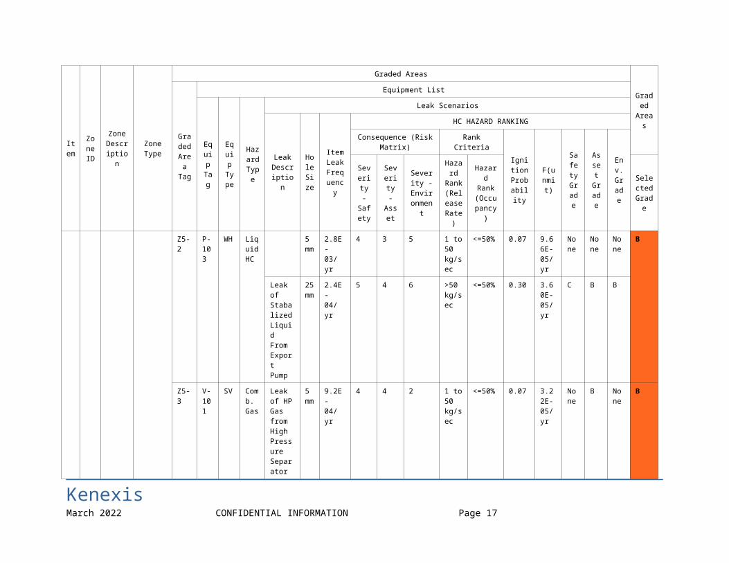
Appendix B – Typical FGS Performance Target List
Item
Zone ID
Zone Description
Zone Type
Graded Areas
Graded
Areas
Graded Area
Tag
Equipment List
Equip Tag
Equip Type
Hazard Type
Leak Scenarios
Leak Descrip
tion
Hole Size
Item Leak Frequency
HC HAZARD RANKING
Consequence (Risk Matrix) Rank Criteria
Ignition
Probability
F(unmit)
Safety Grade
Asset
Grade
Env.
Grade
Severity
- Safe
ty
Severity
- Asse
t
Severity -
Environment
Hazard
Rank (Release
Rate)
Hazard Rank
(Occupancy)
Selected Grad
e
6. Zone 6
Gas Plant - Process Area
H - Hydrocarbon
Z5-1 C-104
1E-1
Comb. Gas
Small Leak of HP Gas from Export Gas Compressor
5 mm
9.2E-02/yr
3 3 3 <1 kg/sec
<=50% 0.01 4.60E-04/yr
None
A None
A
Large Leak of HP Gas from Export Gas Compressor
25 mm
8.0E-03/yr
4 3 3 1 to 50 kg/sec
<=50% 0.07 2.80E-04/yr
C B None
Z5-2 P-103
WH
Liquid HC
5 mm
2.8E-03/yr
4 3 5 1 to 50 kg/sec
<=50% 0.07 9.66E-05/yr
None
None
None
B
Leak of Stabalized Liquid
25 mm
2.4E-04/yr
5 4 6 >50 kg/sec
<=50% 0.30 3.60E-05/yr
C B B
KenexisMay 2023 CONFIDENTIAL INFORMATION Page 13

Item
Zone ID
Zone Description
Zone Type
Graded Areas
Graded
Areas
Graded Area
Tag
Equipment List
Equip Tag
Equip Type
Hazard Type
Leak Scenarios
Leak Descrip
tion
Hole Size
Item Leak Frequency
HC HAZARD RANKING
Consequence (Risk Matrix) Rank Criteria
Ignition
Probability
F(unmit)
Safety Grade
Asset
Grade
Env.
Grade
Severity
- Safe
ty
Severity
- Asse
t
Severity -
Environment
Hazard
Rank (Release
Rate)
Hazard Rank
(Occupancy)
Selected Grad
e
From Export Pump
Z5-3 V-101
SV Comb. Gas
Leak of HP Gas from High Pressure Separator
5 mm
9.2E-04/yr
4 4 2 1 to 50 kg/sec
<=50% 0.07 3.22E-05/yr
None
B None
B
25 mm
8.0E-05/yr
5 4 2 >50 kg/sec
<=100%
0.30 2.40E-05/yr
C C None
V-102
SV Comb. Gas
Leak of LP Gas from Low Pressure Separator
KenexisMay 2023 CONFIDENTIAL INFORMATION Page 14

FGS Zone Grading
KenexisMay 2023 CONFIDENTIAL INFORMATION Page 15

Appendix C – Design Basis Consequence Modeling ResultsThe following figures show typical results of design basis consequence modeling.
KenexisMay 2023 CONFIDENTIAL INFORMATION Page 16
KenexisMay 2023 CONFIDENTIAL INFORMATION Page 17

Appendix D – Typical Fire and Gas Mapping ResultsGeographic Fire Coverage
KenexisMay 2023 CONFIDENTIAL INFORMATION Page 18

Gas Coverage – Scenario and Geographic
KenexisMay 2023 CONFIDENTIAL INFORMATION Page 19

Typical Detector List
The following figure presents a typical fire and gas detector list.
Detector Type TagX
Coordinate
Y Coordinat
e
Elevation Above Grade
Rotation (deg)
Declination (deg) Notes
Point Source Gas Detector (HC)
BTX-001 27' 6" N 26' 0" E 6’ 0” N/A N/A
Point Source Gas Detector (HC)
BTX-002 54' 6" N 14' 6" E 6’ 0” N/A N/A
Point Source Gas Detector (HC)
BTX-003 15' 0" N 14' 6" E 6’ 0” N/A N/A
Point Source Gas Detector (HC)
BTX-004 55' 6" N 7' 6" W 6’ 0” N/A N/A
Point Source Gas Detector (HC)
BTX-005 33' 0" N 17' 0" W 6’ 0” N/A N/A
Point Source Gas Detector (HC)
BTX-006 15' 0" N 7' 6" W 6’ 0” N/A N/A
Optical Fire Detector ATX-001 64' 8" N 35' 8" E 10’ 0” 40° W of
S 35
Optical Fire Detector ATX-002 7' 4" N 40' 2" E 10’ 0” 45° W of
N 35
Optical Fire Detector ATX-003 14' 8" N 7' 2" E 10’ 0” 40° E of
N 35
Optical Fire Detector ATX-004 70' 6" N 3' 8" W 10’ 0” 30° W of
S 35
Optical Fire Detector ATX-005 14' 0" N 18' 0" W 10’ 0” 30° E of
N 35
Note: All detector coordinates are measured relative to the North East corner of the control room building.
KenexisMay 2023 CONFIDENTIAL INFORMATION Page 20