DesigningaConnuousWaveRFCavityfor...
23
Designing a Con+nuousWave RF Cavity for Bunch Rota+on in Support of Experiments Mu2e and g2 Aaron Smith under the mentorship of Joseph Dey, Accelerator Division/RF Department
Transcript of DesigningaConnuousWaveRFCavityfor...
Designing a Con+nuous-‐Wave RF Cavity for Bunch Rota+on in Support of Experiments
Mu2e and g-‐2
Aaron Smith under the mentorship of Joseph Dey, Accelerator Division/RF Department
Beam Bunches
Aaron Smith 2
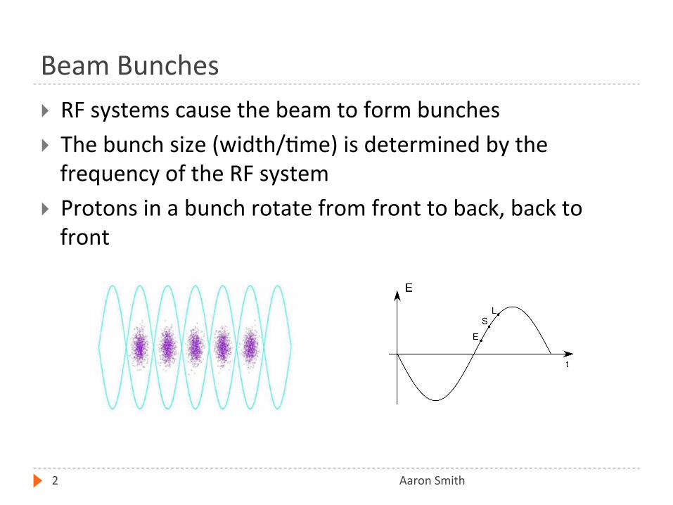
RF systems cause the beam to form bunches The bunch size (width/+me) is determined by the frequency of the RF system
Protons in a bunch rotate from front to back, back to front

Mu2e and g-‐2 requirements
Aaron Smith 3
The same RF system will be used for both experiments g-‐2 requires a smaller bunch length than Mu2e Therefore, RF is being designed to meet g-‐2
Cavi+es also need to be able to run CW (con+nuous wave)
Excessive heat necessitates the design of new cavi+es
Bunch Length Requirements
Full width
Mu2e g-‐2
250 nsec 149 nsec
1° = 31 nsec
Cavity Placement/Use
Aaron Smith 4
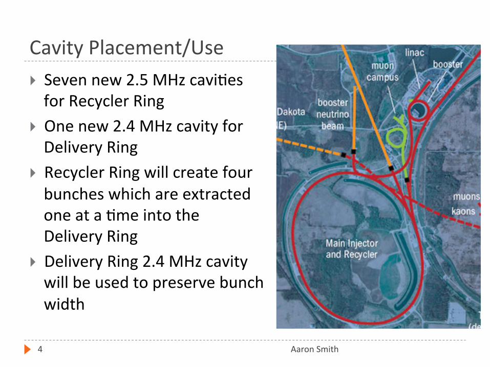
Seven new 2.5 MHz cavi+es for Recycler Ring
One new 2.4 MHz cavity for Delivery Ring
Recycler Ring will create four bunches which are extracted one at a +me into the Delivery Ring
Delivery Ring 2.4 MHz cavity will be used to preserve bunch width
Designing the Cavity
Aaron Smith 5
New cavi+es require Water cooling system
The copper tubing needs to be able to enter/exit the cavity without causing an electrical arc due to poten+al differences
Resonance at 2.4/2.5 MHz This requirement is a condi+on of the experiments and parameters of the accelera+ng systems at Fermilab
Small footprint due to limited tunnel space Sufficient gap voltage (10kV)
Simula+ons of the beam show that the cavi+es need 10kV difference across the gap
A matched load for power transfer efficiency If our cavity does not appear like a 50 ohm system, power will be reflected back into the amplifiers

Resonant Cavity
Aaron Smith 6
Significant factors are: Inner/outer conductor radius Dielectric material Length
The cavity will produce a standing wave similar to the characteris+cs of a quarter wave resonator
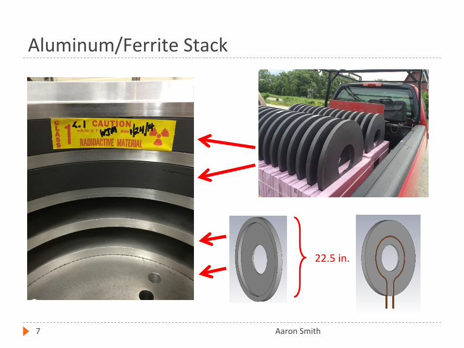
Aluminum/Ferrite Stack
Aaron Smith 7
22.5 in.
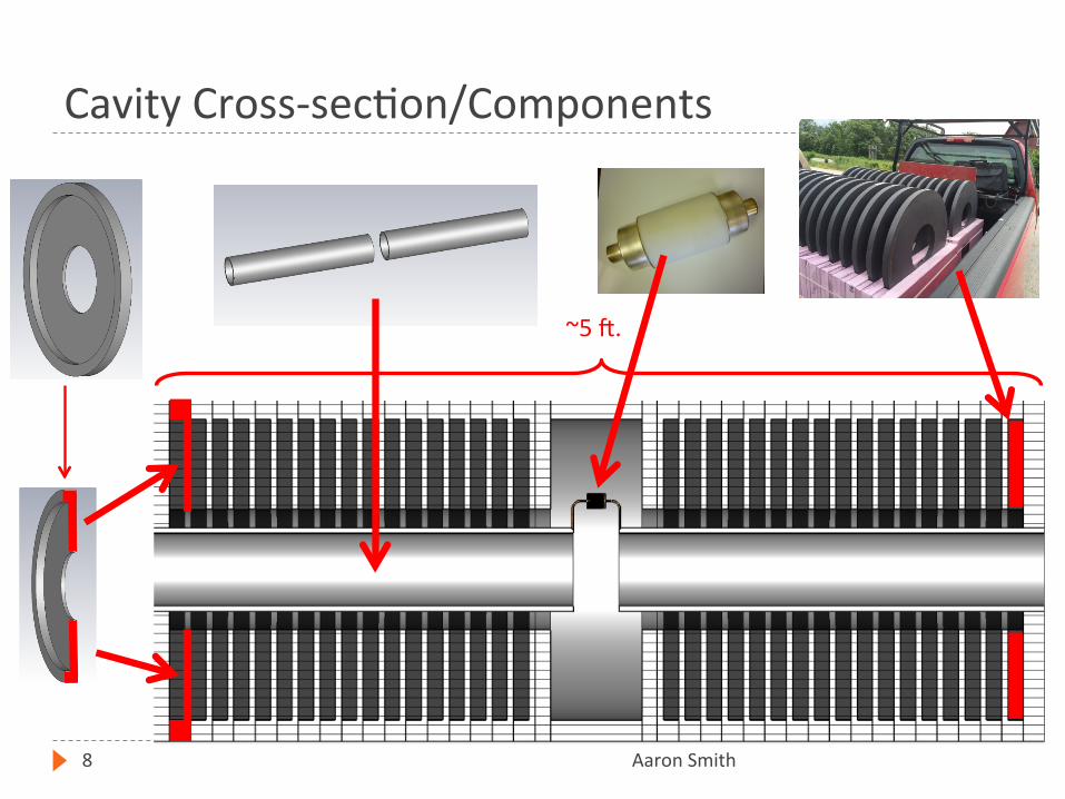
Cavity Cross-‐sec+on/Components
Aaron Smith 8
~5 h.
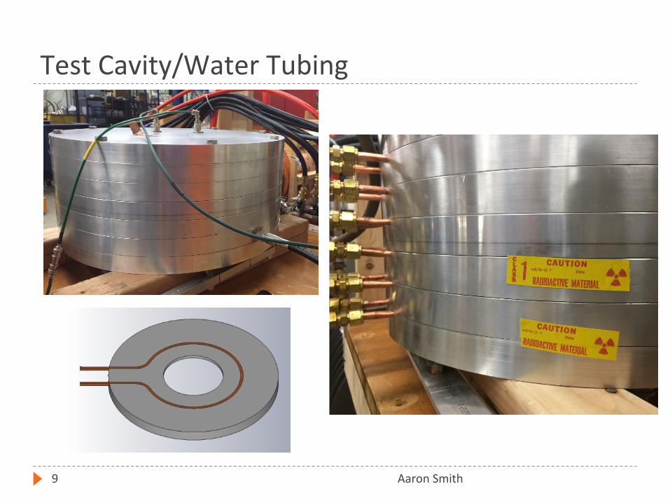
Test Cavity/Water Tubing
Aaron Smith 9
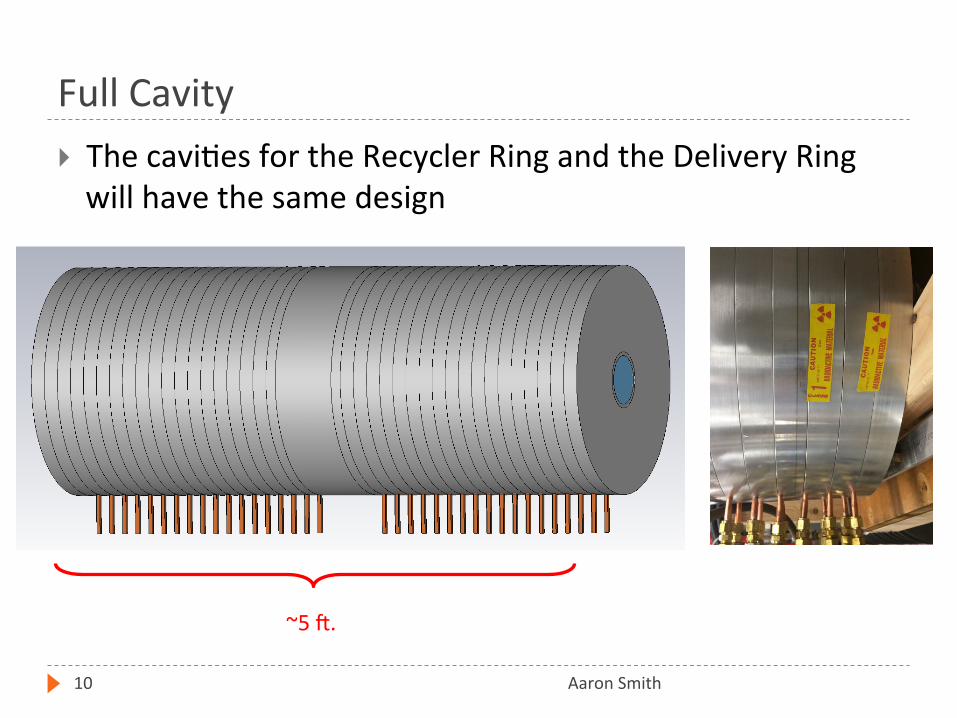
Full Cavity
Aaron Smith 10
The cavi+es for the Recycler Ring and the Delivery Ring will have the same design
~5 h.
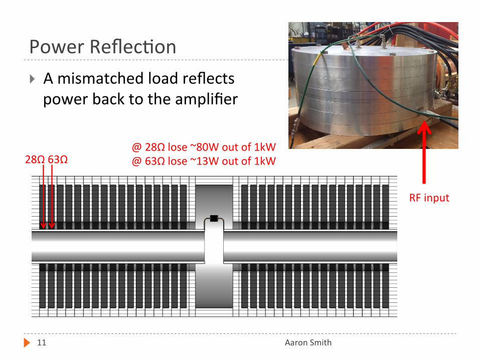
Power Reflec+on
Aaron Smith 11
A mismatched load reflects power back to the amplifier
28Ω 63Ω @ 28Ω lose ~80W out of 1kW @ 63Ω lose ~13W out of 1kW
RF input
Magne+c Hea+ng/Ferrite
Aaron Smith 12
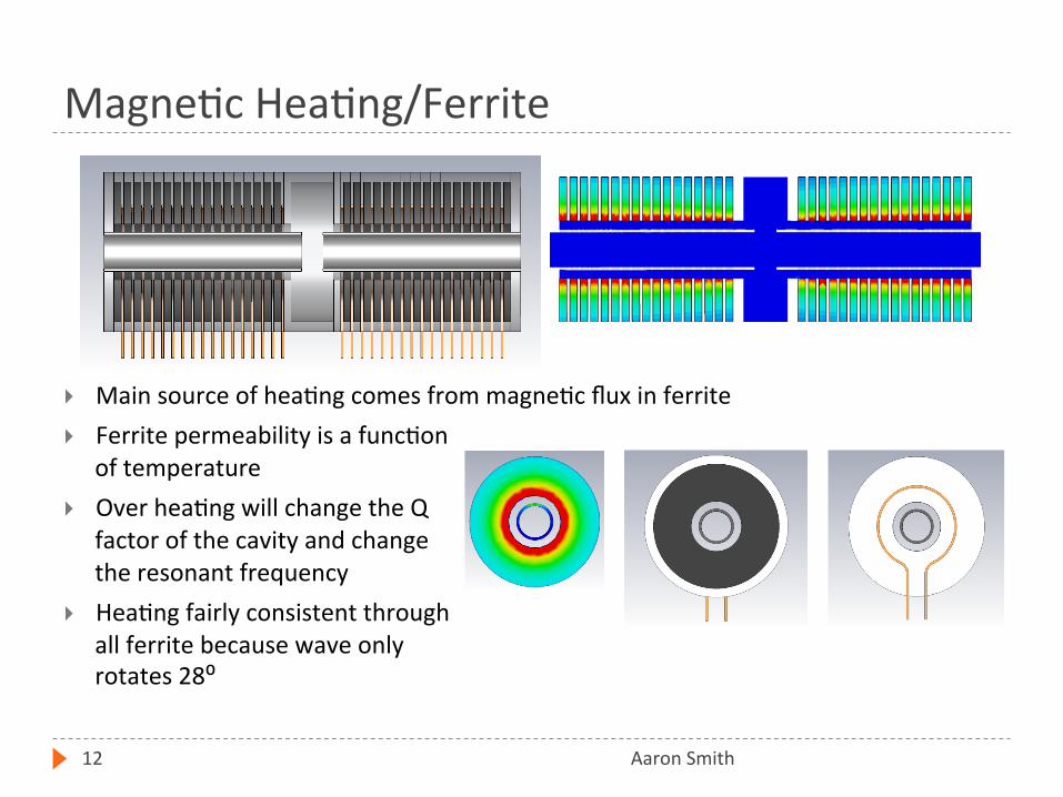
Main source of hea+ng comes from magne+c flux in ferrite Ferrite permeability is a func+on
of temperature Over hea+ng will change the Q
factor of the cavity and change the resonant frequency
Hea+ng fairly consistent through all ferrite because wave only rotates 28⁰

Electrical Arc
Aaron Smith 13
Alters the quality factor of the cavity and changes the resonant frequency Previous cavi+es have had this issue due to water cooling tubing passing
through the outer conductor The copper tubing exited the
cavity through holes in the outer conductor, and were of different poten+al
The new cavity design eliminates this issue by keeping the tubing electrically outside the outer conductor
As the electrical density graph shows, the most likely place for an arc to occur is between the inner conductor, near the gap and the corner of the outer conductor.
At the voltages required, this should not be an issue
Z-‐direc+onal Force
Aaron Smith 14
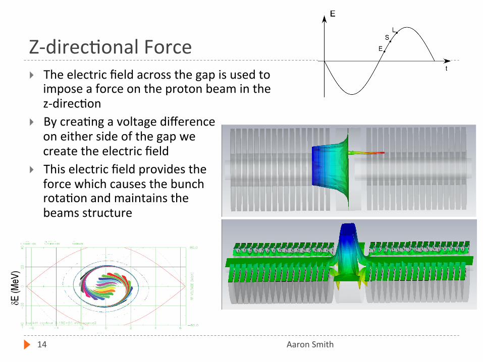
The electric field across the gap is used to impose a force on the proton beam in the z-‐direc+on
By crea+ng a voltage difference on either side of the gap we create the electric field
This electric field provides the force which causes the bunch rota+on and maintains the beams structure
E-‐Field Harmonics
Aaron Smith 15
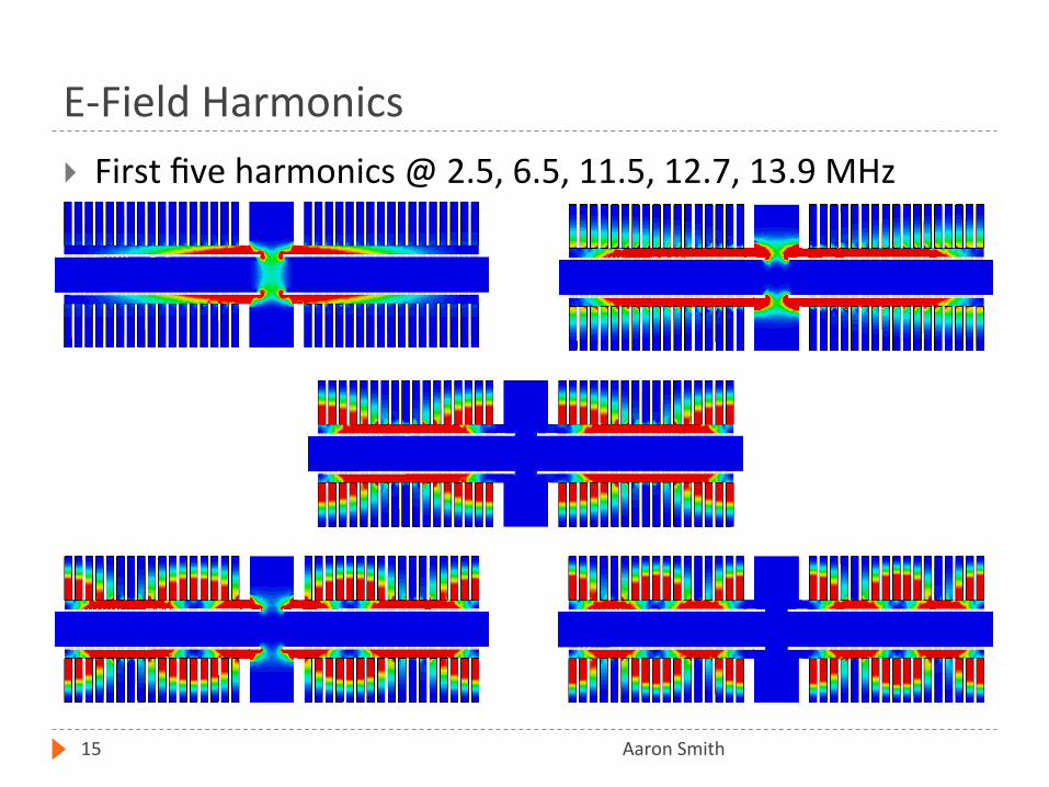
First five harmonics @ 2.5, 6.5, 11.5, 12.7, 13.9 MHz
M-‐Field Harmonics
Aaron Smith 16
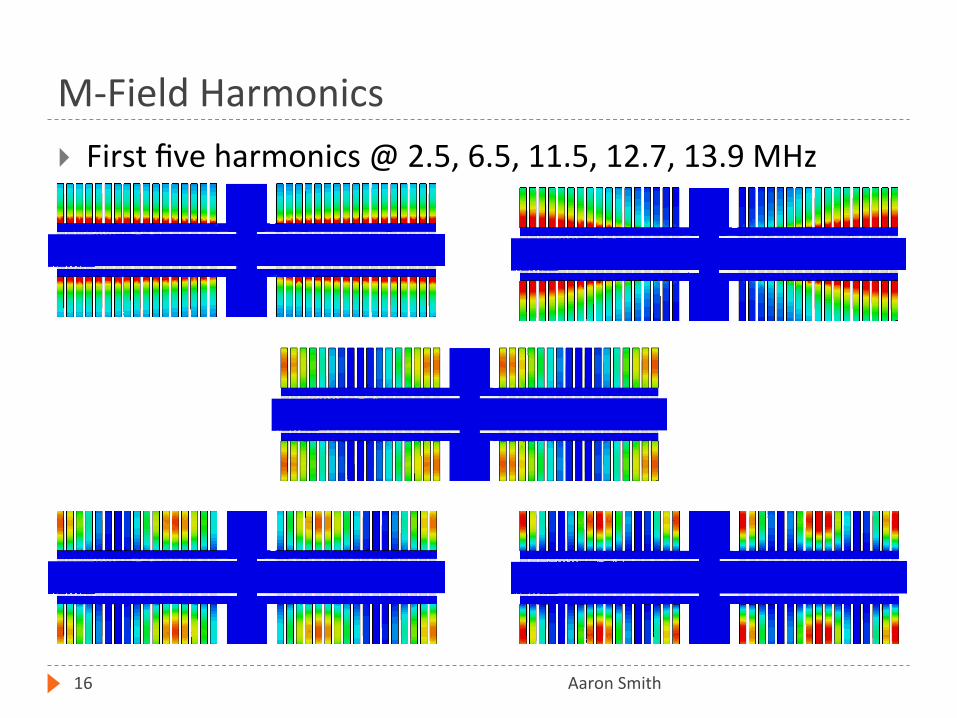
First five harmonics @ 2.5, 6.5, 11.5, 12.7, 13.9 MHz
Induced Currents
Aaron Smith 17
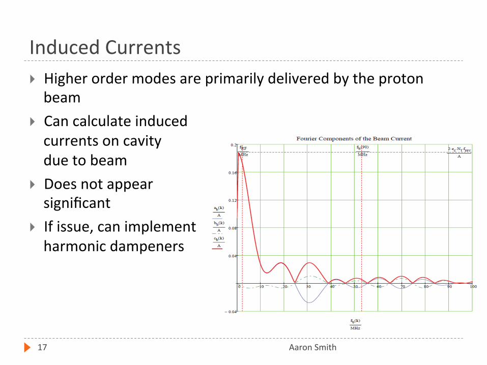
Higher order modes are primarily delivered by the proton beam
Can calculate induced currents on cavity due to beam
Does not appear significant
If issue, can implement harmonic dampeners
Characteris+c Impedance (𝑍↓𝑜 )
Aaron Smith 18
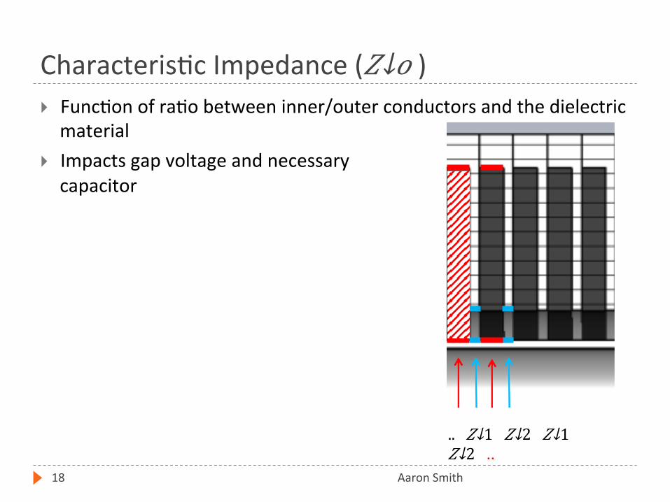
Func+on of ra+o between inner/outer conductors and the dielectric material
Impacts gap voltage and necessary capacitor
.. 𝑍↓1 𝑍↓2 𝑍↓1 𝑍↓2 ..
𝑍↓𝐴𝑣𝑒𝑟𝑎𝑔𝑒
Quality Factor (𝑄)
Aaron Smith 19
The quality factor of a cavity is a ra+o 𝐸𝑛𝑒𝑟𝑔𝑦 𝑆𝑡𝑜𝑟𝑒𝑑 𝑝𝑒𝑟 𝐶𝑦𝑐𝑙𝑒/𝐸𝑛𝑒𝑟𝑔𝑦 𝐿𝑜𝑠𝑠 𝑝𝑒𝑟 𝐶𝑦𝑐𝑙𝑒
Ferrite cavi+es have a low Q compared to super conduc+ng cavi+es
The Q of the cavity is dominated by the Q of the ferrite Test cavity results showed that the aluminum casing and +n finger stock did not have a significant impact on the Q of the cavity
Rshunt (Shunt Impedance)
Aaron Smith 20
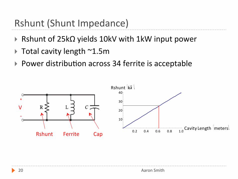
Rshunt of 25kΩ yields 10kV with 1kW input power Total cavity length ~1.5m Power distribu+on across 34 ferrite is acceptable
0.2 0.4 0.6 0.8 1.0Cavity Length HmetersL10
20
30
40Rshunt HkW L
Ferrite Rshunt Cap
⁺ V ₋
Conclusions
Aaron Smith 21
By using circuit models, CST Microwave Studio and a five ferrite test cavity we Showed proof of concept of the cavity design Demonstrated the sufficiency of the water cooling system Found the cavi+es characteris+c impedance and Q factor Determined an appropriate Rshunt for the needed voltage Iden+fied the size of the capacitors Calculated the appropriate RF input point on the cavity Determined the frequency of the higher order modes

Special Thank You
Aaron Smith 22
Joseph Dey SIST Commiqee Members
Sandra Charles, Linda Diepholz, Dianne Engram, Gustavo Canselo, Bill Freeman, Ellioq McCrory, Vivian O’Dell, David Peterson, and Mayling Wong-‐Squires
RF Department
Ques+ons?
Aaron Smith 23