
Designing a Self-Powered Device to Aid in Fencing Training ...
45
Union College Union | Digital Works Honors eses Student Work 6-2013 Designing a Self-Powered Device to Aid in Fencing Training and Scoring Zak Smolen Union College - Schenectady, NY Follow this and additional works at: hps://digitalworks.union.edu/theses Part of the Computer Engineering Commons is Open Access is brought to you for free and open access by the Student Work at Union | Digital Works. It has been accepted for inclusion in Honors eses by an authorized administrator of Union | Digital Works. For more information, please contact [email protected]. Recommended Citation Smolen, Zak, "Designing a Self-Powered Device to Aid in Fencing Training and Scoring" (2013). Honors eses. 731. hps://digitalworks.union.edu/theses/731
Transcript of Designing a Self-Powered Device to Aid in Fencing Training ...

Union CollegeUnion | Digital Works
Honors Theses Student Work
6-2013
Designing a Self-Powered Device to Aid in FencingTraining and ScoringZak SmolenUnion College - Schenectady, NY
Follow this and additional works at: https://digitalworks.union.edu/theses
Part of the Computer Engineering Commons
This Open Access is brought to you for free and open access by the Student Work at Union | Digital Works. It has been accepted for inclusion in HonorsTheses by an authorized administrator of Union | Digital Works. For more information, please contact [email protected].
Recommended CitationSmolen, Zak, "Designing a Self-Powered Device to Aid in Fencing Training and Scoring" (2013). Honors Theses. 731.https://digitalworks.union.edu/theses/731

Designing a Self-Powered Device
to Aid in Fencing Training and Scoring
By
Zak Smolen
* * * * * * * * *
Submitted in partial fulfillment
of the requirements for
Honors in the Department of Electrical and Computer Engineering
UNION COLLEGE
June, 2013

ii
ABSTRACT SMOLEN, ZAK Designing a Self-Powered Device to Aid in Fencing Training and
Scoring. Department of Electrical and Computer Engineering, June 2013.
ADVISOR: Prof. James Hedrick
The purpose of this project is to redesign a currently available electric
training tool for the sport of fencing in order to fix several existing faults such as
cost and power use. The second stage of this project uses this new low-power
design to explore small-scale energy harvesting by integrating a charging
mechanism into the device to generate power from the movements of the fencer.
This goal of this project is to research and explore modern low-power
device design, at both the hardware and software levels, and then to apply those
techniques to improve a real-world product. The final result of this product is an
improved and affordable fencing training tool, as well as an alternative power
supply design for the device that uses energy harvesting to charge and power
the device and remove the need for batteries or an external charger.
The first step of this project was to implement the core functions with low
power requirements. The microcontroller I selected was the PIC12F1840, an 8-
bit, low-power microcontroller. The power consumption was minimized in both
hardware and software designs.
The base device has low enough power consumption that replacing the
battery with an energy-harvesting power supply is possible. The energy
harvester uses a piezoelectric element for power generation and a super
capacitor for storage in place of a battery.

iii
Table of Contents
Abstract ................................................................................................................................ ii
Background .......................................................................................................................... 2 Design of Current Similar Products ...................................................................................... 2 Small Scale Energy Harvesting................................................................................................ 4
Design Requirements ....................................................................................................... 6 Cost ................................................................................................................................................... 6 Power Supply ................................................................................................................................ 7 Hit Detection ................................................................................................................................. 7 Indicators ....................................................................................................................................... 8 Ergonomics .................................................................................................................................... 8
Design ..................................................................................................................................... 9 Power Supply and Storage ....................................................................................................... 9 Hit Detection Hardware ......................................................................................................... 11 Hit Detection and Timing Software .................................................................................... 13 Indicators .................................................................................................................................... 13 Prototype Cost ........................................................................................................................... 14
Testing Preliminary Design Hit Response .............................................................. 14
Energy Harvesting Development ............................................................................... 16 Measuring the Fencers’ Motion ........................................................................................... 16 Analyzing the Acceleration Data ......................................................................................... 18 Designing the Energy Harvesting Circuit ......................................................................... 22 Testing the Final Prototype .................................................................................................. 25
Conclusion ......................................................................................................................... 27
Future Work ...................................................................................................................... 28 Fixing the Current Design ...................................................................................................... 28 Expanding the Design.............................................................................................................. 29
References ......................................................................................................................... 30
Appendix A: PIC12F1840 Source Code Header File ............................................ 31
Appendix B: PIC12F1840 Source Code Code File ................................................. 32
Appendix C: Tri-Accelerometer Source Code ........................................................ 37

iv
Table of Figures
Figure 1. Inside view of the tip of an electric épée. 5 Figure 2. Inside view of a buzz box. 6 Figure 3. Block diagram of the overall device design 9 Figure 4. Prototype board layout for hit detection circuit (left) and circuit schematic
(right). 11 Figure 5. Input from non-debounced (left) and debounced (right) épée. 12 Figure 6. Hit detection and timing system state diagram. 17 Figure 7. Schematic of the pulse generator for testing. 15 Figure 8. Tri-axis accelerometer with plug cover removed. 16 Figure 9. Arduino shield for wireless tri-axis accelerometer. 21 Figure 10. Accelerations measured during control tests. 19 Figure 11. Accelerations measured during fencing tests. 20 Figure 12. Simplified diagram of energy harvesting device layout. 23 Figure 13. Populated prototype board shown next to U.S. quarter. 24
1
Introduction
The sport of fencing has evolved over the years by introducing electrical
scoring systems in order to accurately detect when fencers hit, determine if a hit is
on- or off-target, and conform to the International Fencing Federation timing rules.
These systems are large, expensive, and cumbersome for quick or casual fencing.
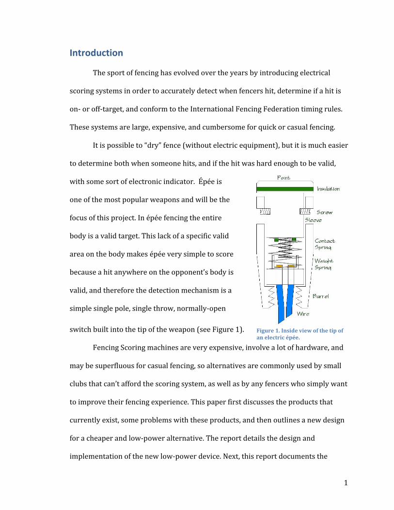
It is possible to “dry” fence (without electric equipment), but it is much easier
to determine both when someone hits, and if the hit was hard enough to be valid,
with some sort of electronic indicator. Épée is
one of the most popular weapons and will be the
focus of this project. In épée fencing the entire
body is a valid target. This lack of a specific valid
area on the body makes épée very simple to score
because a hit anywhere on the opponent’s body is
valid, and therefore the detection mechanism is a
simple single pole, single throw, normally-open
switch built into the tip of the weapon (see Figure 1).
Fencing Scoring machines are very expensive, involve a lot of hardware, and
may be superfluous for casual fencing, so alternatives are commonly used by small
clubs that can’t afford the scoring system, as well as by any fencers who simply want
to improve their fencing experience. This paper first discusses the products that
currently exist, some problems with these products, and then outlines a new design
for a cheaper and low-power alternative. The report details the design and
implementation of the new low-power device. Next, this report documents the
Figure 1. Inside view of the tip of an electric épée.

2
testing of the low-power design followed by the design and implementation of the
energy harvesting addition. Finally, this report discusses what needs to be done to
fix the energy harvesting design as well as further improvements that could be
made to the overall design.
Background On the market, there are currently devices available called “buzzboxes” that
can be plugged into the épée in order to indicate when a fencer hits a target, without
requiring them to use a full scoring system. Because fencing is not a mainstream
sport and there are only a few sources for the specialized equipment, simple devices
like this are often overpriced. The first part of this project looks to redesign the
simple buzzbox in order to address many of its problems.
Design of Current Similar Products
The first issue is the cost. Commercial buzzboxes cost $40-50 each, and are
most likely bought in pairs since fencing bouts
involve two fencers. The most expensive part of
this commercially available device is usually the
metal enclosure. The actual electrical components
inside the device only cost around $5-10.
Considering that the nature of the device is
essentially just a special continuity tester, $40 is
Figure 2. Inside view of a buzz box.

3
extremely high.
The second issue with the commercially available product is that it is poorly
designed and uses power inefficiently. Figure 2 shows the buzzbox with the top of
the enclosure removed. I opened up the device and disassembled the circuit in order
to reverse-engineer the design. The circuit in the device is made up of a 12V “A23”
battery to power a TTL octal inverter logic chip, an inductive buzzer, and an LED.
Only four of the inverters are used to make a ring oscillator and drive the inductive
buzzer. The battery that came with the device is rated at around 12V 60mAh, which
is necessary due to current requirements of the buzzer and LED. This battery is
large, compared to how much space is available next to the fencer’s hand, and adds a
significant amount to the weight of the device. “A23” batteries are actually made up
of 8 “LR932” watch batteries, and there are no rechargeable versions so there is an
added environmental impact from disposing of the batteries.
Another issue with this product that the new design could address is the user
experience and ergonomics of the device. There are only two different pitches
available for the buzzers, so it is confusing to have multiple bouts occurring near
each other because there will be more than one fencer with the same buzzer sound.
The size and weight of the device is also a consideration. The commercially
available device has a metal enclosure and a relatively large battery, which changes
the balance of the weapon by a small, but noticeable, amount. The dimensions of the
enclosure are 4 x 5 x 1.7cm, which seems small, but due to its thickness the buzzbox
may press uncomfortably on the fencer’s hand depending on the style of the fencers’
grip and manner in which they hold the weapon.

4
The current buzzboxes use very simple circuits, and as such they respond to
any sort of contact instead of only valid hits. The addition of precision timing
according to the FIE rules would increase the realism of the fencing experience. The
exact timing of the duration for a valid hit is controlled by a single variable in the
program code and the device could easily be reprogrammed to accommodate any
future changes in timing rules.
In researching the electronics of fencing equipment for this project, I found
many small networks of fencers who had some electrical experience and wanted to
create their own scoring machines or similar devices. A common justification was
that they ran a small club and couldn’t afford the expensive machines and reels.
They could not make anything that could be officially used in tournaments since
their devices would not be FIE certified, but there were discussions of designs for
scoring machines and other similar devices. I would like to release both the software
and hardware of my design as open source, and possibly offer a kit or fully
assembled devices so that other fencers who don’t have access to manufacturing
equipment or experience assembling circuits could benefit from this project.
Small Scale Energy Harvesting
The second part of this project takes my newly-designed buzzbox and adds
an energy harvesting system to provide power and remove the need for disposable
batteries or external recharging. The idea of devices with an integrated generator
has such practical applications as survival equipment (think shake flashlight, crank
radios), but as the energy-harvesting equipment gets cheaper and more efficient, the
uses have branched out. Solar panels, despite their inefficiencies, are now being

5
used on devices such as outdoor lighting (small lights that charge during the day
then turn on at night). Some other examples of smaller-scale energy-harvesting
applications are battery-less remotes (using the pressing of buttons to power the
remote) and wireless sensor networks.
The current state of technology has limits in terms of how efficiently power
can be generated and how much power can be generated affordably. If the device
can be redesigned to more efficiently use power, then it would be practical to use
currently available energy-harvesting devices. For example, if the nodes of a
wireless sensor network are efficient enough, then they could rely only on their
energy harvesters for power and remain in the field indefinitely without replacing
or recharging batteries.
In this project, the motion of fencing will be used to generate energy to
power the device. There are many options for energy-harvesting devices such as
inductive, piezoelectric, or Macro-Fiber Composite (MFC) elements. The most likely
candidates for this sort of device are piezoelectric or MFC elements.
Piezoelectric elements generate a voltage when compressed, expanded,
flexed, or twisted. Conversely, they also can expand, contract, or flex when a voltage
is applied to them. The output voltage range is quite varied and depends largely on
the properties of the device. However, a common feature that is inherent to this type
of element is that the current will be small. This means that, especially for small-
scale devices, any losses can greatly reduce the efficiency; therefore aspects such as
rectification must be implemented very efficiently.

6
Many piezoelectric energy-harvesting devices are based on cantilevers or
other similarly structured mechanisms, and therefore have a resonant frequency
where they are most efficient. There are also designs to harvest energy from very
low frequency (or totally independent) events.
Macro-Fiber Composite elements were created by NASA and consist of many
strands of Piezoceramic fibers bonded to a flexible substrate. MFC’s have many
similar properties as simple Piezoceramic devices, but can be used more easily to
harvest energy from non-resonant sources. They are also especially good at
harvesting energy from flexing sources and vibrations. Unfortunately they are still
very new and usually expensive since they are custom made for each application.
In my research I have also come across Microelectromechanical (MEMS)
inductive generators. These are also usually custom built for specific projects and
are currently not very efficient, and therefore would not be practical as a possible
energy-harvesting device for this project.
One example of a similar application is energy-harvesting shoes. The shoes
use the impacts from walking to generate electricity that could be used to charge the
user’s cell phone or other similar devices.
Design Requirements
Cost
I would like for my final design to cost less than $40. This is the cost of the
current product, so if my project is cheaper, it would be a viable alternative. The
project will be a prototype so it will cost more than a final, commercially-produced

7
product. The self-charging version may also use some uncommon components but,
even with those considerations, it should still be reasonable to make the low
powered version for under $40. The self-charging mechanism will possibly bring the
cost above $40 if it uses uncommon or expensive parts, but due to the modular
nature of the device, this feature would be an optional addition.
Power Supply
In terms of power supply and usage, my design focuses on flexibility and
efficient circuits. The current device uses a 12V battery rated around 60mAh and
when the indicator is, on the current drain from the battery is around 26mA. The
goal of this project is to reduce the current and overall power usage as low as
possible. The precise value will depend on the energy storage component of the
power supply but in all of the designs the current shouldn’t exceed 10mA. In order
to test the power supplies I will take simple current measurements with the device
at rest and while the indicator is on.
Hit Detection The hit detection portion of this project should conform to FIE (International
Fencing Federation) timing rules while still being as energy efficient as possible. The
FIE timing rules for épée state that the tip must be depressed on the opponent’s
body for 3-5ms in order to be valid. My project will implement this by timing using a
threshold of 4ms. The microcontroller will time for an actual 4ms and the
debouncing circuit on the input should not add much more of a delay but even up to
1ms of an extra delay from the debouncer would still allow for FIE timing rules.

8
Indicators The indicators will be designed with the same modular nature as the rest of
the device so that any sort of indicating device could be added with minimal change
to the circuit. The most useful indicators are a buzzer and LED, but other options
(such as an RF transmitter to activate remote indicators) could be used instead. The
indicator module must run off of the same power supply as the hit detection circuit
but can include an integrated DC-DC converter to increase the voltage. Components
like piezo transducers should include driver circuitry to allow for easy operation.
The buzzer should also have an output frequency between 5-15 kHz. Simple
components such as an LED could also include driver circuitry to decrease power
usage.
A less important and currently optional feature for my project would be to
have the buzzer frequency be variable. This could be tuned with a potentiometer or
even selected from a few discrete values. The differences between the buzzer tones
do not have to be large, only audibly different.
Ergonomics The ergonomics of the device are not as important as the electrical design
goals, but they should not be neglected. The current device is both heavy and large
enough to be uncomfortable for some fencers. The device must have an enclosure
that is strong enough to not shatter if it gets hit, but still light enough that it will not
offset the weight of the épée noticeably. The device must also be small enough that it
will not press on the fencer’s hand during use. Finally, all switches and indicators on
the device must be appropriately positioned for ease of use and view. All of these
9
factors will be tested objectively by myself and other fencers, and adjusted
according to user feedback.
Design
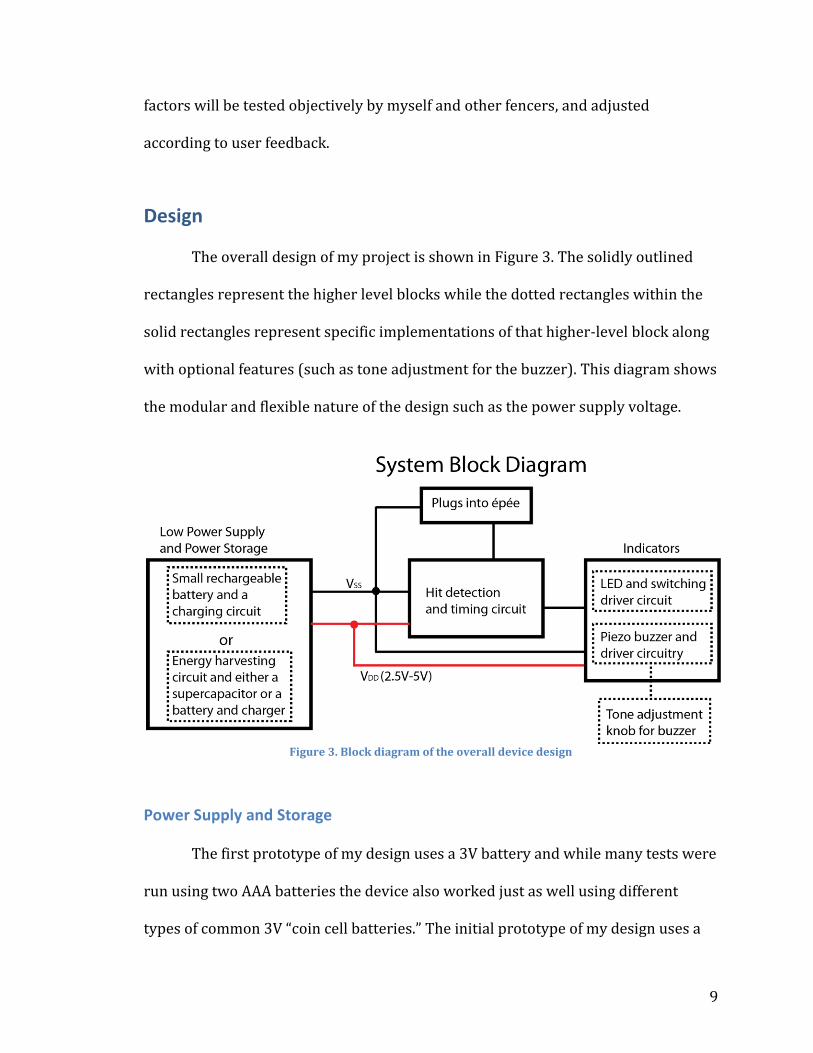
The overall design of my project is shown in Figure 3. The solidly outlined
rectangles represent the higher level blocks while the dotted rectangles within the
solid rectangles represent specific implementations of that higher-level block along
with optional features (such as tone adjustment for the buzzer). This diagram shows
the modular and flexible nature of the design such as the power supply voltage.
Figure 3. Block diagram of the overall device design
Power Supply and Storage
The first prototype of my design uses a 3V battery and while many tests were
run using two AAA batteries the device also worked just as well using different
types of common 3V “coin cell batteries.” The initial prototype of my design uses a

10
3V battery and only around 16µA of current when the device is in its sleep state
while waiting for the hit, an initial spike at 0.65mA when the indicator is first turned
on, and 0.6mA for the two seconds that the indicator is on. The indicator current
could be decreased with a driver circuit or more efficient indicating devices.
The second prototype uses a rechargeable Polymer Lithium Ion (LiPo)
battery that is rated at 3.7V. LiPo is known for its high- energy density and a battery
rated at 40mAh is only 12 x 16 x 5mm and weighs around 2 grams. I also considered
rechargeable coin cell type batteries that range from 1.5V to 3.6V based on their
chemistries but decided that LiPo would be the best choice due to its high-energy
density, higher voltage (which was plenty for the microcontroller and increased the
intensity of the indicators from the 3V system), small size, and relative ease to
recharge. There were many tiny and easy-to-use LiPo charging integrated circuits. I
used both the MCP73831 IC from Microchip and the MAX1555 IC from Maxim, the
latter of which is specifically designed to charge from a USB plug or an AC adapter.
The final design uses an energy-harvesting mechanism to generate power
and a super capacitor for storage in place of a battery. The energy-harvesting device
used is a cantilever type piezoelectric element that is connected to the LTC3588
integrated circuit from Linear Technology. This IC rectifies and stores the voltage
from the piezo element and then outputs a user-selectable buck converter regulated
voltage once a certain threshold has been reached. This output will be stored in a
super capacitor, which is connected in parallel to the microcontroller’s power
supply input and ground pins.

11
Hit Detection Hardware
The hit detection circuit is implemented using a PIC12F1840
microcontroller. This microcontroller was chosen for reasons which include:
Flexible and low power supply requirements (2.3-5.5V) Low-power sleep capabilities Many peripheral modules like Capacitive sensing, PWM, SR-latch, interrupt-
on-change (IOC), and more Multiple timers, one 16-bit timer that can operate during sleep
Figure 4. Prototype board layout for hit detection circuit (left) and circuit schematic (right).
In my original design I planned to use the capacitive sensing capabilities of
the PIC12F1840 to detect a hit. The other weapons have specific target area and are
covered by a metal mesh vest so capacitive sensing seemed like a possible way of
detecting contact on valid targets for all weapons. However, this proved to be
difficult and not energy efficient, so I switched to using the interrupt-on-change to
detect the hits when the input pin was shorted to ground by the épée tip switch.

12
Figure 5. Input from non-debounced (left) and debounced (right) épée.
The prototype board layout for the hit detection circuit shown in Figure 4
includes an ICSP header for reprogramming and flexible input and output footprints.
This allowed me to use the board at all stages of prototyping and testing. It is only
around 1in2 in size using all through-hole components. A final surface-mount
version of this board, or even the version with the energy-harvesting power supply,
can be much smaller.
The schematic of the hit detection circuit (Figure 4) shows the simple nature
of the board. The épée-tip switch input is debounced with a simple passive circuit
and the output from that the debouncing circuit is connected to a pin that has
interrupt-on-change enabled. Figure 5 shows the results from the addition of the
debouncing circuit. At first I had difficulty getting reliable triggering using this
circuit, but it turned out that I was using too large of a capacitor the delay was too
large and the slope was too gradual to reliably trigger the interrupt-on-change
module. Through trial-and-error I found that a capacitor value around 4.7nF or
5.2nF worked to provide consistent triggering without detecting bounces.

13
Hit Detection and Timing Software
The hit detection and
timing software is implemented
using a state machine (Figure 6).
The program is structured to
turn off any features when they
are not needed and have the
microcontroller enter a low-
power sleep state whenever
possible. When the initial hit
comes in, the interrupt-on-change (generated from the épée tip being depressed)
wakes up the microcontroller. If after 4ms the tip is still depressed, then the hit is
considered valid. The indicators are turned on for two seconds (during which the
microcontroller goes to sleep) and then turned off and the microcontroller returns
to the initial sleep state. With the addition of an energy-harvesting mechanism the
device’s power may not be too constant so the software is designed to be able to
recover from resetting at any point or if it somehow enters any other incorrect state.
Indicators
The current buzzer is a simple piezo buzzer module with a self-contained
driver. These buzzers are not the most efficient but they were the easiest to
implement because they only need a DC input.
The current design of my project includes a driver on the LED. The idea is to
actually blink the LED fast enough so that the human eye would see it as a solid (or
Figure 6. Hit detection and timing system state diagram.

14
very rapidly blinking) light. This would mean that the LED would actually be on for
less time and therefore would draw less power. Unfortunately, my current designs
for driver circuitry were not able to drive the LED (with the buzzer connected in
series) at the supply voltage; instead they required a higher voltage with the
additional fault of having a higher current draw then just powering the components
directly without any driver circuitry.
Prototype Cost
The total cost for the rechargeable low-power prototype is around $15-20. In
large-scale production many of these parts would cost much less than they cost for
me to purchase them in single or very small quantities. This cost also accounts for
an approximation of the cost of the PCB. This is a good baseline since it is half of the
cost of my original maximum goal.
Testing Preliminary Design Hit Response
In order to test that my device would only respond to hits that are between
3ms and 5ms (as defined in the FIE rules) I designed a simple pulse generator
circuit (Figure 7) based off of a classic 555 timer monostable timer circuit. The pulse
generator was attached to the weapon inputs of the board and simulated épée hits
at different pulse lengths. I added edge triggering to the 555 timer circuit because
the input pulse (pressing a switch) cannot be longer than the output pulse in
monostable configuration, and I could not reliably press a switch fast enough. The
output is inverted so that it provides a negative pulse to simulate depressing the tip
of the épée, which connects a pin to ground in my circuit. The R and C slots are

15
empty sockets that I put in to accommodate a variety of sizes of resistors and
capacitors. The resistor and capacitor determine the output period of the pulse
generator according to the equation 1.1 × R × C. For example, using a 1µF capacitor
and 2.2kΩ resistor the period would be around 2.4ms, which is too short, but with a
1µF capacitor and 4.7kΩ resistor the period would be around 5.17ms. I could use
resistors and capacitors measured at high precision to fine tune the pulse length.
Figure 7. Schematic of the pulse generator for testing.
The pulse generator was used to test the circuit’s response to pulses of
different lengths, some less than 4ms and some greater. By very slowly and
gradually changing the values of the resistor I was able to determine that the
threshold of the pulse length that the device would react to was 3.75ms (confirmed
with an oscilloscope). This threshold falls between the 3-5ms range defined in the
FIE rules and is close to the original goal of 4ms. Therefore, I considered it an
acceptable result.

16
Energy Harvesting Development
Measuring the Fencers’ Motion
In order to choose the best type of piezoelectric element (as well as its
physical orientation) to harvest energy from the fencer’s movements, I measured
the accelerations present during different types of fencing. I created a tri-axis
accelerometer system (Figure 8) that mounted on the épée in the same location as
the device would. This way the measurements taken would provide an accurate
picture of actual accelerations that the device would be experiencing.
Figure 8. Tri-axis accelerometer with plug cover removed.
The accelerometer shown in Figure 8 consists of an Arduino Pro mini
connected to a LIS331 accelerometer board. The LIS3331 IC is a tri-axis
17
accelerometer that can measure accelerations (in g’s where
1g 9.81 ms2
) at user
selectable ranges of ±6g, ±12g, or ±24g. The chip can communicate with I2C or SPI. I
chose to use SPI since it was a little easier to implement both physically and in the
software. The Arduino part of the device was strapped to the fencer’s wrist with
elastic bands and then connected to the computer by a long USB plug that allowed
the fencer a few meters of travel forwards and backwards. The board measured the
accelerations at set intervals and transmitted the values in a simple comma or
space-delimited string. The computer recorded the readings and saved them (along
with a timestamp) to a CSV file. I originally had the program average multiple
readings to reduce noise before transmitting them, but I decided to remove this
once I looked at the data in order to get higher resolution readings from the
accelerometer.
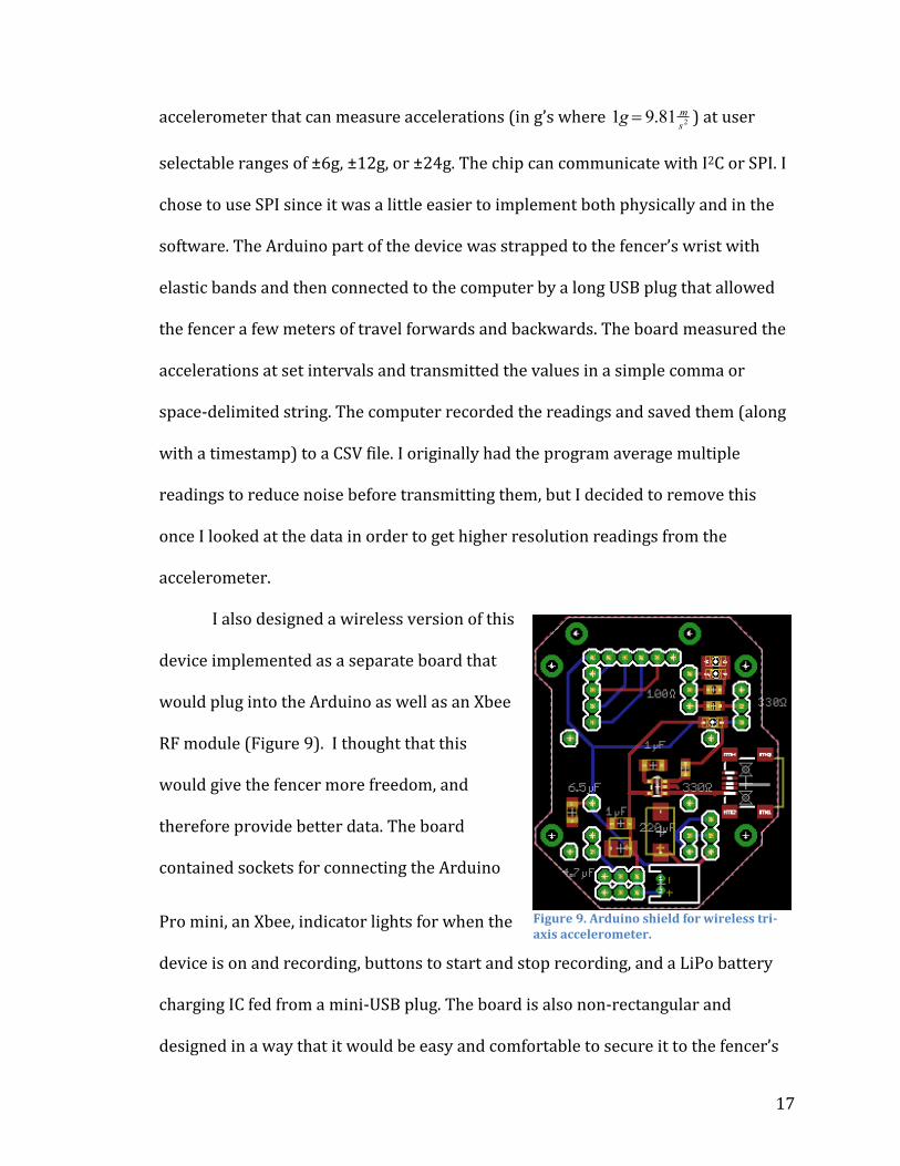
I also designed a wireless version of this
device implemented as a separate board that
would plug into the Arduino as well as an Xbee
RF module (Figure 9). I thought that this
would give the fencer more freedom, and
therefore provide better data. The board
contained sockets for connecting the Arduino
Pro mini, an Xbee, indicator lights for when the
device is on and recording, buttons to start and stop recording, and a LiPo battery
charging IC fed from a mini-USB plug. The board is also non-rectangular and
designed in a way that it would be easy and comfortable to secure it to the fencer’s
Figure 9. Arduino shield for wireless tri-axis accelerometer.

18
forearm using the two large holes on each side and an adjustable strap.
Implementing this device required only a few lines of code to be added in order to
configure the Xbee (for both the Arduino and computer programs). Ultimately, I
decided that the data that I measured with the wired version was satisfactory and
therefore I did not implement this board.
Analyzing the Acceleration Data
In order to get a better understanding of the accelerations present, I tested
two scenarios with two different fencers using different fencing styles. I first
recorded a “control” situation where the fencer was moving around as one would
during a normal bout, but no blade contact was made and no hits were scored. This
was an important scenario because it wouldn’t make sense for the device to only
work if the fencer were actually hitting the opponent’s weapon or body since it
needs to be able to charge up before any contacts are actually made. I then recorded
actual “fencing” situations where the fencers were actively engaging their
opponent’s blade and successfully hitting their opponent.
The control data (Figure 10) showed many interesting aspects of the fencers’
movements. The X-axis and Y-axis data show similar patterns of high frequency
oscillations followed by short periods of a constant or slightly changing acceleration.
This result is most likely from the circular motion of the hand that is common to
many fencers, but even periods of time where there were mostly left-right or up-
down movements by the fencer look similar in the data. It is interesting to note that
the Y-axis data centers on
9.8 m
s2 due to gravity. The Z-axis data was rapidly

19
changing. This was interesting to see since there was no blade or body contact. The
changes were large, but the frequency was largely varied and highly inconsistent.
Figure 10. Accelerations measured during control tests.
The fencing data (Figure 11) showed very different results than the control
data. The data is a whole order of magnitude larger at its peaks, and the axes now
each have some unique characteristics. The X-axis has large impulse-like peaks and
some other smaller peaks, but the magnitude of the acceleration in between hitting
the opponent’s blade or (less frequently) swinging very hard left or right is very
small. The Y-axis data shows a different trend. There are still peaks when the blades
hit but they are not as large as seen in the X-axis. There is a lot more fluctuation
overall, though at a higher magnitude than the X-axis. The Z-axis data actually looks
somewhat similar to the other two axes. There are constant fluctuations like the Y-
axis but there are also large impulse-like peaks in the acceleration.

20
Figure 11. Accelerations measured during fencing tests.
In addition to plotting the data I also looked at the derivatives and integrals
of the data. The derivative results did not indicate any new trends that I hadn’t seen
in the acceleration graphs, and the integral data was not of much use either. I also
decided to use a Fourier transform to analyze the power spectrum of the data. While
I know that every fencer moves differently, I wanted to see if there were any similar
trends. I used interpolation to normalize the data so that I could perform the Fourier
Transform. I did not get much more useful data from this analysis since the data
wasn’t very periodic, but I did see that while the X-axis and Z-axis had some power
at different frequencies, the Y-axis was dominated by a single component around 0.
This is again likely due to the acceleration of gravity.
While I did not get any definitive results from my measurements and
analysis, I did get enough to support my choice of element and orientation to use for
21
energy harvesting. I decided from the beginning that I was going to use some sort of
piezoelectric element instead of an element like an inductive generator (similar to
what would be found in a shake flashlight) because I didn’t want heavy moving parts
such as a free-moving magnet. Moving parts would make noise and could possibly
throw off the weight of the weapon if they were too heavy. I decided that a
cantilever type piezoelectric element (with a weight on the end) would probably be
the best option since there was a lot of up-down and left-right motion. This type of
element generates energy from flexing and has a very large frequency response
(from almost DC to the Gigahertz range). While flexible cantilever elements may not
produce as much energy some other rigid piezo elements (such as the disk type
commonly seen in guitar pickups and audio transducers), they can still typically
produce tens to hundreds of volts. During the control test there was a lot of up-
down and left-right motion and, while there are no set movements that a fencer
must follow, no fencer can (nor would they want to) keep their hand perfectly still
while moving around during the bout.
I decided to mount the element in the Y-axis for two reasons. First, this axis
seemed to have the most consistent movement between the two tests. While there
were some sharper impulses during the fencing test when blade contact was made
there was also constantly oscillating acceleration that was higher in magnitude than
that experienced in the X-axis. Also, due to gravity, the cantilever would have a
natural rest position and constant downward acceleration. This would allow it to
flex more easily with less of a chance of the element twisting than there would be in
the X-axis.

22
Designing the Energy Harvesting Circuit
In order to rectify, store, and regulate the output from the piezoelectric
element I used the LTC3588 IC from Linear Technology and a supercapacitor rated
at 1F 2.5V with very low effective series resistance (around 0.1Ω). The LTC3588
contains a low-loss bridge rectifier and a highly efficient buck converter and can
charge a capacitor up from the input source in order to provide a constant output
voltage at up to 100mA. The output voltage can be set to 1.8V, 2.5V, 3.3V or 3.6V. In
my circuit I set the output to 2.5V because it was above the threshold of the
microcontroller (the PIC12F1840 can operate from 2.3-5.5V) and it was the voltage
rating of the supercapacitor. While it is common practice to use capacitors rated at
twice the voltage needed in their application (due to tolerances and wear on the
dielectric) this supercapacitor can safely operate at 2.5V for an extended period of
time.
I chose to use a supercapacitor instead of a battery for storage for a few
reasons. First, I did not want to have to step the voltage up too high and end up with
too small an available current. Batteries require a higher charging voltage than their
nominal voltage while supercapacitors, like any capacitor, charge up to whatever
voltage they are attached to. Also, many supercapacitors are using light materials
like aerogels as a dielectric and therefore, would weigh less than a similarly-sized
battery.

23
Figure 12. Simplified diagram of energy harvesting device layout.
While integrating the energy harvesting power supply into my prototype I
considered both electrical and physical design. Figure 12 shows a block diagram of
both the circuit and physical layout of the device. The core of the device is the same
as my original low-powered prototype: the PIC12F1840 is used to detect the hit
from the debounced épée tip switch and it indicates valid hits with a buzzer and
LED. The difference in this design is that the power supply pin of the
microcontroller is connected in parallel with the output of the LTC3588 energy
harvesting IC and the 1F supercapacitor. This way the supercapacitor will charge up
and then act in place of a battery to power the microcontroller.
The supercapacitor is mounted sideways on the board below the piezo
element. The element is mounted perpendicular to the board so that it will flex in
the Y-axis as the fencer’s hand moves.

24
Figure 13. Populated prototype board shown next to U.S. quarter.
Figure 13 shows the constructed energy-harvesting prototype. Since this is
not my final design, I still used a through-hole version of the PIC12F1840
microcontroller instead of the substantially smaller SMD version so that the chip
would be easy to remove and reprogram if needed. The LTC3588 comes in very
small packages only and has a ground pad underneath the main body of the chip,
which makes it difficult to solder. I used heat-shrink tubing to cover the metal casing
of the crystal so that it would not cause a short between the power and ground
traces since it is bent to the side over those traces in order to lie flat. The piezo
element is attached with a pad on each side of the board and the base of the
cantilever is also secured with superglue. Ideally the enclosure would further
reinforce this connection and stabilize the base of the cantilever. The piezo element
and supercapacitor are located far enough away that the element will have a full
range of motion. Even with the through-hole chip the whole board is still only

25
slightly larger than a U.S. quarter, and about 4 times as thick as one. It also only
weighs around 6 grams, again only slightly more than a quarter.
Testing the Final Prototype
When I tested the energy-harvesting prototype I found that it did not work.
After troubleshooting for a while I found that when I tested the power and ground
traces on the printed circuit board with a continuity tester, I detected a short. After
removing and resoldering all of the main parts I still found this problem so I thought
that the capacitor might have somehow been damaged in my assembly or testing.
When I tested the capacitor I found that it acted as a short. I also tested another 1F
2.5V capacitor that I had, which had not been used at all, and came up with the same
results.
This led me to research and think more about supercapacitors. While they
are charging, capacitors act like a short to the circuit they are connected to. Once
they are charged they act like a break in the circuit and a source of power to
connected components. Supercapacitors are very large capacitors so they act like a
short for much longer than normal capacitors. Unfortunately, my 1F capacitor is so
large that it is not charging up at a usable rate.
During my testing I also found that the output from the LTC3588 was not
what I expected. At first I thought that I may have made errors in designing or
assembling the circuit, but I tested all of the components individually and they
matched the specifications outlined in the LTC3588 datasheet. I did find that the
piezo element I was using was not giving me the output I expected (10-50V), even
when I excited it more than it would typically be excited during fencing. I even

26
tested another larger element that I had from the same company and I still did not
get a consistently high enough output to properly power the device.
One final issue I uncovered was charging the supercapacitor. The LTC3588 is
capable of using many different inputs other than piezo elements and it can even use
a DC source (like a solar panel or battery). I tried connecting a battery to the input
and watching the voltage on the supercapacitor which only increased at a very small
and slow rate (a few millivolts per minute). Part of the problem that may be causing
this is that the supercapacitor I am using is too large. Another possible issue is the
parallel connection between the LTC3588 output, the supercapacitor, and the
microcontroller. I believe that some of the little power I was getting out of the
LTC3588 was going to the microcontroller instead of charging up the
supercapacitor. This seems like it shouldn’t be a problem; I want to power the
microcontroller after all, but the already reduced output I was getting from the
LTC3588 was not enough to both power the microcontroller (which needs a steady
and relatively constant voltage and 2 second bursts of current) and charge up the
large supercapacitor.
A positive aspect of my energy-harvesting prototype is that its total cost was
only around $20-25. This is only slightly more than my original design and again
well within my goal. Even with the addition of a case the overall cost should still be
well within the $40 limit.

27
Conclusion
The purpose of this project was to explore low-power device design as well
as small-scale energy harvesting by applying these ideas to an existing product. I
redesigned a training tool used in the sport of fencing to provide a better indication
of when the fencer hits their opponent.
The first stage of my project was to design a new device from scratch. I
disassembled and studied the original product and then designed a low-power
device that addressed the problems that I found in the original. I tried to maximize
the efficiency of power usage so that it would be feasible to add an energy
harvesting system later on. I ran my prototype first from a 3V coin cell battery and
then from a 3.7V rechargeable LiPo battery with only around 16µA of current draw
when the device is in its sleep state while waiting for the hit, an initial spike at
0.65mA when the indicator is first turned on, and 0.6mA for the two seconds that
the indicator is on.
The next stage of my project was to design an energy-harvesting power
supply, which would generate electricity from the motion of the fencer and power
the device in place of a battery system. I researched different methods of small-scale
energy harvesting and studied the motion of the fencers in order to determine that
the best type of element for my application was a piezoelectric cantilever flexing in
the Y-axis. While both the low-power device and the energy-harvesting power
supply circuit worked individually they did not work when combined together with
a supercapacitor for energy storage. This problem seems to have two causes:

28
insufficient output from the piezo elements and improper charging of the
supercapacitor.
Although my final result did not work I still consider this project a success. I
very much enjoyed working on this project and will continue to work on it until I fix
the problems with the energy-harvesting power supply. I enjoyed the fact that this
project combined skills and knowledge from all of my engineering courses at Union:
I had to design the analog and digital portions of the electrical circuit, measure and
analyze data in the frequency and time domains, and program the microcontroller in
C, and, in some original sections of my software, in assembly. I was also able to make
use of some of my other interests such as circuit board design and assembly.
Future Work
Fixing the Current Design
I would like to first address the problems with my current piezo elements
and try new piezo elements. I will test them without the microcontroller in the
circuit (or on a new board purpose built for testing the LTC3588 circuit) and see if
larger elements, or some other configuration of elements, would give me a better
output.
I will then work on the supercapacitor problem. I will look into other types
and values of supercapacitors as well as supercapacitor charging circuits. I might
still be able to use the 1F 2.5V supercapacitor that I have now with the addition of a
charging circuit, or I might need both a smaller supercapacitor as well as a charging
circuit.

29
Larger or better piezo elements, new supercapacitors, and supercapacitor
charging circuitry will increase the cost of the device but since the prototype was far
under budget the increased total cost of the device should still be less than $40.
I will work to solve both of these problems before Steinmetz Symposium in
order to have a working prototype to display. I would like to design and construct
an enclosure for the final device. I would like to make it out of some sort of plastic in
order to reduce weight and cost but I would have to make sure that it is durable
enough to hold up to a possible graze or hit by an opponent’s weapon. I will first
design and 3D print some initial enclosures and once I have finished developing the
design I will look into manufacturing it from other materials.
Expanding the Design It would be nice to implement an adjustable buzzer feature so that the
devices could make different sounds without the need for different hardware. In
order to do this I need to actually design an efficient piezo transducer driving circuit
that will produce an output at a single, but adjustable, frequency. This could either
be adjusted by an analog dial (potentiometer) or by selecting between a few preset
frequencies.

30
References Grace, E.A.; Rajan, S.E.; Asis, A.A.C.; , "Performance evaluation of different rectifiers for Piezo-electric energy harvesting applications," Recent Advancements in Electrical, Electronics and Control Engineering (ICONRAEeCE), 2011 International Conference on , vol., no., pp.248-252, 15-17 Dec. 2011 http://ieeexplore.ieee.org/stamp/stamp.jsp?tp=&arnumber=6129810&isnumber=6129721 D'hulst, R.; Driesen, J.; , "Power processing circuits for vibration-based energy harvesters," Power Electronics Specialists Conference, 2008. PESC 2008. IEEE , vol., no., pp.2556-2562, 15-19 June 2008 http://ieeexplore.ieee.org/stamp/stamp.jsp?tp=&arnumber=4592325&isnumber=4591876 Lefeuvre, E.; Audigier, D.; Richard, C.; Guyomar, D.; , "Buck-Boost Converter for Sensorless Power Optimization of Piezoelectric Energy Harvester," Power Electronics, IEEE Transactions on , vol.22, no.5, pp.2018-2025, Sept. 2007 http://ieeexplore.ieee.org/stamp/stamp.jsp?tp=&arnumber=4300887&isnumber=4300856 Optimal configurations of bistable piezo-composites for energy harvesting D. N. Betts, H. A. Kim, C. R. Bowen, and D. J. Inman, Appl. Phys. Lett. 100, 114104 (2012), DOI:10.1063/1.3693523 Khaligh, A.; Peng Zeng; Cong Zheng; , "Kinetic Energy Harvesting Using Piezoelectric and Electromagnetic Technologies—State of the Art," Industrial Electronics, IEEE Transactions on , vol.57, no.3, pp.850-860, March 2010 http://ieeexplore.ieee.org/stamp/stamp.jsp?tp=&arnumber=5071287&isnumber=5410131 Daue, Thomas P, Jan Kunzmann, and Andreas Schonecker. “ENERGY HARVESTING SYSTEMS USING PIEZO-ELECTRIC MACRO FIBER COMPOSITES.” Components (2008) http://www.smart-material.com/media/Publications/EnergyHarvest/EH-usingthe MFC.pdf Sodano, Henry Angelo. Macro-Fiber Composites for Sensing, Actuation and Power Generation. Virginia Polytechnic Institute and State University, 2003-07-28. . VTLS. 17 May 2012 http://scholar.lib.vt.edu/theses/available/etd-08012003-105114 Rules for Competitions Book 3. Material Rules. N.p.: n.p., n.d. British Fencing. Web. 3 Sept. 2012. <http://www.britishfencing.com/governance/rules/fie-rules/>.

31
Appendix A: PIC12F1840 Source Code Header File /* * File: main.h * Author: zaksmolen * Created on October 11, 2012, 1:19 PM */ #include <stdio.h> #include <stdlib.h> #include <xc.h> #include <pic12f1840.h> #ifndef MAIN_H #define MAIN_H #ifdef __cplusplus extern "C" { #endif // This method sets the internal clock to 31kHz (lowest freq.) void set_internal_clock_31k(void); // This method sets the internal clock to 62.5kHz void set_internal_clock_62_5k(void); // This method sets the internal clock to 125kHz void set_internal_clock_125k(void); // This method configures the initial status of the SFR's void init_config(void); // This method configures the initial status of the SFR's void disable_all(void); // This enum defines the states for the program enum{ /*Enum construct declares states */ WAIT_FOR_HIT, START_HIT_TIMER, TIME_HIT_DURATION, INDICATE_HIT } state; #ifdef __cplusplus } #endif #endif /* MAIN_H */

32
Appendix B: PIC12F1840 Source Code Code File /* * File: main.c * Author: zaksmolen * Created on October 7, 2012, 6:24 PM */ #include <stdio.h> #include <stdlib.h> #include <xc.h> #include <pic12f1840.h> #include "main.h" // ports and pins #define indic_out LATA2 // output for indicators (LED and/or buzzer) #define hit_input !RA3 // input for hit detection using interrupt-on-change void main() { //========== CONFIG and set SFRs========== #pragma config FOSC = INTOSC, WDTE = OFF, PWRTE = OFF, MCLRE = OFF, CP = OFF #pragma config CPD = OFF, BOREN = ON, CLKOUTEN = OFF, IESO = ON, FCMEN = ON #pragma config WRT = OFF, PLLEN = OFF, STVREN = ON, BORV = LO, LVP = OFF // init all other SFR's and timer settings and such init_config(); // Turn on the oscillator circuit for Timer 1 T1OSCEN = 1; // Set initial state to waiting for hit state = WAIT_FOR_HIT; //========== PROGRAM LOOP ========== for(;;) { switch(state) { /* turn all interrupts and indicators off but enable IOC3 for the hit * detection then go to sleep. */ case(WAIT_FOR_HIT): disable_all(); SLEEP(); //asm("NOP"); break; /* * The ISR detected a hit so start Timer 0 to time for around 4ms. */ case(START_HIT_TIMER): IOCAN3 = 0;

33
// preload Timer 0 with 192. 192 is 3/4 of 256 and this value will allow // the timer to time 4ms with a 62.5 kHz clock (since it uses Fosc/4) TMR0 = 192; // Enable Timer 0 interrupt (and clear flag) TMR0IF = 0; TMR0IE = 1; // go to hit timing state state = TIME_HIT_DURATION; break; /* * This is a waiting state since, the µc can't * sleep while using timer 0. */ case(TIME_HIT_DURATION): // some sort of nothing loop or just nothing so it // keeps executing the switch-case statement //asm("NOP"); break; /* * This is a state to turn on the indicators. */ case(INDICATE_HIT): // turn indicator output on indic_out = 1; // clear Timer 1 (high and low bytes) TMR1H = 0; TMR1L = 0; // start Timer 1 TMR1ON = 1; // timer 1 interrupt enabled TMR1IE = 1; // now go to sleep and wait for interrupt to turn off SLEEP(); //asm("NOP"); break; // In case of mess ups or something unexpected default: // go back to waiting loop state = WAIT_FOR_HIT; break; } } }

34
//================ Helper Functions ================= /* * This method configures the initial status of the SFR's */ void init_config(void) { PEIE = 1; // all peripheral interrupts are enabled GIE = 1; // global interrupts enabled IOCIE = 1; // Interrupt on change enabled // Set System clock to use internal oscillator SCS0 = 1; SCS1 = 1; // Disable software PLL SPLLEN = 0; //set the internal clock to 62.5 kHz //set_internal_clock_62_5k(); //set the internal clock to 125 kHz set_internal_clock_125k(); //Timer 0 config nWPUEN = 0; // weak pullups enabled by individual WPUA# bits TMR0CS = 0; // clock from Internal instruction cycle (FOSC/4) PSA = 1; // don't assign prescaler //Timer 1 config // TMRCS<1:0> = 00 and T1OSCEN = 1 for osc. circuit on pins (2 and 3) TMR1CS0 = 0; TMR1CS1 = 1; TMR1GE = 0; nT1SYNC = 1; // set Timer 1 to asynchronous // Set port 2 (pin 5) as a digital output for indicators TRISA2 = 0; // Set port 3 (pin 4) as a input (with weak pull-up) for hit detection TRISA3 = 1; IOCAP3 = 1; //disable positive edge interrupt on change IOCAN3 = 0; //enable negative edge interrupt on change } /* * This method sets the internal clock to 62.5kHz * (62.5 kHz clock) * 256 * (1, NO PRESCALER) = 4.09600 milliseconds */ void set_internal_clock_62_5k(void) { // Set internal oscillator frequency: 0100 = 62.5 kHz IRCF3 = 0; IRCF2 = 1;

35
IRCF1 = 0; IRCF0 = 0; } /* * This method sets the internal clock to 125kHz */ void set_internal_clock_125k(void) { IRCF3 = 0; IRCF2 = 1; IRCF1 = 0; IRCF0 = 1; } /* * This method disables all interrupts, indicators, and other peripheral circuitry * (like Timer 1). The method also enables IOC3 for the hit detection. */ void disable_all(void) { // turn indicator off indic_out = 0; // turn Timer 1 off TMR1ON = 0; // clear Timer 1 TMR1H = 0; TMR1L = 0; // turn off interrupts TMR1IE = 0; TMR0IE = 0; // clear flags IOCAF3 = 0; IOCIF = 0; TMR0IF = 0; TMR1IF = 0; // Enable IOC3 (and global interrupts) GIE = 1; IOCIE = 1; IOCAN3 = 1; } //==================== INTERRUPT ==================== /* * This is the interrupt service routine */ void interrupt ISR(void) { PORTA; // read PORT A to clear mismatch conditions // If Interrupt was from IOC if ((state == WAIT_FOR_HIT) && IOCAF3)

36
{ // if the top is still down if (hit_input) { IOCIE = 0; // Start 4ms timer 0 state = START_HIT_TIMER; } } // if interrupt was from timer 0 overflow else if ((state == TIME_HIT_DURATION) && TMR0IF) { // check if tip is down if (hit_input) { // hit was valid state = INDICATE_HIT; } else { // hit was not valid state = WAIT_FOR_HIT; } } // if interrupt was from timer 1 overflow else if ((state == INDICATE_HIT) && TMR1IF) { state = WAIT_FOR_HIT; } // if there is some other case just go back to waiting else { state = WAIT_FOR_HIT; } // Clear and reset everything IOCAF3 = 0; IOCIF = 0; TMR0IF = 0; TMR1IF = 0; asm("RETFIE"); }

37
Appendix C: Tri-Accelerometer Source Code // 3-axis Accelerometer // using Sparkfun Electronics Triple Axis Accelerometer Breakout - LIS331 // and an Arduino Pro Mini (3.3v) /* Wiring: Ard. LIS331 3.3V VCC GND GND 10 CS 11 SDA/SDI 12 SA0/SDO 13 SCL/SPC */ #include <SPI.h> #include <stdlib.h> #include <stdio.h> #include <avr/io.h> // Definition of interrupt names #include <avr/interrupt.h> // ISR interrupt service routine #define SS 10 // Serial Select -> CS on LIS331 #define MOSI 11 // MasterOutSlaveIn -> SDI #define MISO 12 // MasterInSlaveOut -> SDO #define SCK 13 // Serial Clock -> SPC on LIS331 //#define BTN 3 // button to start/stop #define SWITCH 2 // switch to start/stop #define SWITCH_VCC 3 // pin supplying VCC to the switch // charlieplexed LED to show start/stop #define LED1 7 #define LED2 6 #define DELAYVAL 50 // delay time after making readings //#define AVG_COUNT 1 #define SCALE 0.0007324 // approximate scale factor for full range (+/-24g) // scale factor: +/-24g = 48G range. 2^16 bits. 48/65536 = 0.0007324 //#define SCALE 0.00718260498; // approximate scale factor for full range (+/-24g) in m/s^2 // scale factor: +/-24g = 48G range. 2^16 bits. 48/65536 * 9.80665 = 0.00718260498 #define SEPERATOR ',' // this is the seperator for the output // global acceleration values

38
double xAcc, yAcc, zAcc; void setup() { Serial.begin(9600); // Configure SPI SPI_SETUP(); // Configure accelerometer Accelerometer_Setup(); // configure interrupt and LED pinMode(LED1, OUTPUT); // sets the digital pin as output for LED pinMode(LED2, OUTPUT); // sets the digital pin as output for LED pinMode(SWITCH, INPUT); // read from the switch pin pinMode(SWITCH_VCC, OUTPUT); // power for the switch pin digitalWrite(SWITCH_VCC, HIGH); } void loop() { if (digitalRead(SWITCH) == HIGH) { digitalWrite(LED1, HIGH); digitalWrite(LED2, LOW); readVal(); // get acc values and put into global variables Serial.print(xAcc, 3); Serial.print(SEPERATOR); Serial.print(yAcc, 3); Serial.print(SEPERATOR); Serial.println(zAcc, 3); delay(DELAYVAL); } else { digitalWrite(LED1, LOW); digitalWrite(LED2, HIGH); } } // Read the accelerometer data and put values into global variables void readVal() { byte xAddressByteL = 0x28; // Low Byte of X value (the first data register) byte readBit = B10000000; // bit 0 (MSB) HIGH means read register byte incrementBit = B01000000; // bit 1 HIGH means keep incrementing registers byte dataByte = xAddressByteL | readBit | incrementBit; byte b0 = 0x0; // an empty byte, to increment to subsequent registers

39
// init the variables to 0 int xVal = 0; int yVal = 0; int zVal = 0; digitalWrite(SS, LOW); // SS must be LOW to communicate delay(1); SPI.transfer(dataByte); // request a read, starting at X low byte byte xL = SPI.transfer(b0); // get the low byte of X data byte xH = SPI.transfer(b0); // get the high byte of X data byte yL = SPI.transfer(b0); // get the low byte of Y data byte yH = SPI.transfer(b0); // get the high byte of Y data byte zL = SPI.transfer(b0); // get the low byte of Z data byte zH = SPI.transfer(b0); // get the high byte of Z data delay(1); digitalWrite(SS, HIGH); // shift the high byte left 8 bits and merge the high and low xVal += (xL | (xH << 8)); yVal += (yL | (yH << 8)); zVal += (zL | (zH << 8)); xAcc = xVal * SCALE; yAcc = yVal * SCALE; zAcc = zVal * SCALE; } void SPI_SETUP() { pinMode(SS, OUTPUT); // start up the SPI bus SPI.begin(); // This device reads MSB first: SPI.setBitOrder(MSBFIRST); SPI.setDataMode(SPI_MODE0); /* SPI.setClockDivider() sets SPI clock to a fraction of the system clock Arduino Pro 3.3V system clock = 8 MHz */ SPI.setClockDivider(SPI_CLOCK_DIV8); // SPI clock 1000Hz } void Accelerometer_Setup() { // Set up the accelerometer // write to Control register 1: address 20h byte addressByte = 0x20;

40
/* Bits: PM2 PM1 PM0 DR1 DR0 Zen Yen Xen PM2PM1PM0: Power mode (001 = Normal Mode) DR1DR0: Data rate (00=50Hz, 01=100Hz, 10=400Hz, 11=1000Hz) Zen, Yen, Xen: Z enable, Y enable, X enable */ byte ctrlRegByte = 0x37; // 00111111 : normal mode, 1000Hz, xyz enabled // Send the data for Control Register 1 digitalWrite(SS, LOW); delay(1); SPI.transfer(addressByte); SPI.transfer(ctrlRegByte); delay(1); digitalWrite(SS, HIGH); delay(100); // write to Control Register 2: address 21h addressByte = 0x21; // This register configures high pass filter ctrlRegByte = 0x00; // High pass filter off // Send the data for Control Register 2 digitalWrite(SS, LOW); delay(1); SPI.transfer(addressByte); SPI.transfer(ctrlRegByte); delay(1); digitalWrite(SS, HIGH); delay(100); // write to Control Register 4: address 23h addressByte = 0x23; /* Bits: BDU BLE FS1 FS0 STsign 0 ST SIM BDU: Block data update (0=continuous update) BLE: Big/little endian data (0=accel data LSB at LOW address) FS1FS0: Full-scale selection (00 = +/-6G, 01 = +/-12G, 11 = +/-24G) STsign: selft-test sign (default 0=plus) ST: self-test enable (default 0=disabled) SIM: SPI mode selection(default 0=4 wire interface, 1=3 wire interface) */ ctrlRegByte = 0x30; // 00110000 : 24G (full scale) // Send the data for Control Register 4 digitalWrite(SS, LOW); delay(1); SPI.transfer(addressByte); SPI.transfer(ctrlRegByte); delay(1); digitalWrite(SS, HIGH); }