DESIGN STANDARD DS 60 · DESIGN STANDARD DS 60 Water Supply Distribution Standard Pipelines Other...
76
Assets Delivery Group Engineering DESIGN STANDARD DS 60 Water Supply Distribution Standard Pipelines Other than Reticulation VERSION 5 REVISION 1 DECEMBER 2017
-
Upload
dinhkhuong -
Category
Documents
-
view
243 -
download
1
Transcript of DESIGN STANDARD DS 60 · DESIGN STANDARD DS 60 Water Supply Distribution Standard Pipelines Other...
Assets Delivery Group Engineering
DESIGN STANDARD DS 60
Water Supply Distribution Standard
Pipelines Other than Reticulation
VERSION 5
REVISION 1
DECEMBER 2017

Design Standard No. DS 60
Water Supply Distribution - Pipelines Other Than Reticulation
Uncontrolled if Printed Page 2 of 76 Ver5 Rev1
© Copyright Water Corporation 1999-2017
FOREWORD
The intent of Design Standards is to specify requirements that assure effective design and delivery of fit for
purpose Water Corporation infrastructure assets for best whole-of-life value with least risk to Corporation
service standards and safety. Design standards are also intended to promote uniformity of approach by asset
designers, drafters and constructors to the design, construction, commissioning and delivery of water
infrastructure and to the compatibility of new infrastructure with existing like infrastructure.
Design Standards draw on the asset design, management and field operational experience gained and
documented by the Corporation and by the water industry generally over time. They are intended for
application by Corporation staff, designers, constructors and land developers to the planning, design,
construction and commissioning of Corporation infrastructure including water services provided by land
developers for takeover by the Corporation.
Nothing in this Design Standard diminishes the responsibility of designers and constructors for applying the
requirements of WA OSH Regulations 1996 (Division 12, Construction Industry – consultation on hazards
and safety management) to the delivery of Corporation assets. Information on these statutory requirements
may be viewed at the following web site location:
https://www.slp.wa.gov.au/legislation/statutes.nsf/law_s4665.html
Enquiries relating to the technical content of a Design Standard should be directed to the Principal Engineer,
Water Conveyance Section, Engineering. Future Design Standard changes, if any, will be issued to
registered Design Standard users as and when published.
Head of Engineering
This document is prepared without the assumption of a duty of care by the Water Corporation. The document is not intended to be
nor should it be relied on as a substitute for professional engineering design expertise or any other professional advice.
Users should use and reference the current version of this document.
© Copyright – Water Corporation: This standard and software is copyright. With the exception of use permitted by the Copyright
Act 1968, no part may be reproduced without the written permission of the Water Corporation.

Design Standard No. DS 60
Water Supply Distribution - Pipelines Other Than Reticulation
Uncontrolled if Printed Page 3 of 76 Ver5 Rev1
© Copyright Water Corporation 1999-2017
DISCLAIMER
Water Corporation accepts no liability for any loss or damage that arises from anything in the
Standards/Specifications including any loss or damage that may arise due to the errors and omissions of any person.
Any person or entity which relies upon the Standards/Specifications from the Water Corporation website does so
that their own risk and without any right of recourse to the Water Corporation, including, but not limited to, using
the Standards/Specification for works other than for or on behalf of the Water Corporation.
The Water Corporation shall not be responsible, nor liable, to any person or entity for any loss or damage suffered
as a consequence of the unlawful use of, or reference to, the Standards/Specifications, including but not limited to
the use of any part of the Standards/Specification without first obtaining prior express written permission from the
CEO of the Water Corporation.
Any interpretation of anything in the Standards/Specifications that deviates from specific Water Corporation
Project requirements must be referred to, and resolved by, reference to and for determination by the Water
Corporation’s project manager and/or designer for that particular Project.
Design Standard No. DS 60
Water Supply Distribution - Pipelines Other Than Reticulation
Uncontrolled if Printed Page 4 of 76 Ver5 Rev1
© Copyright Water Corporation 1999-2017
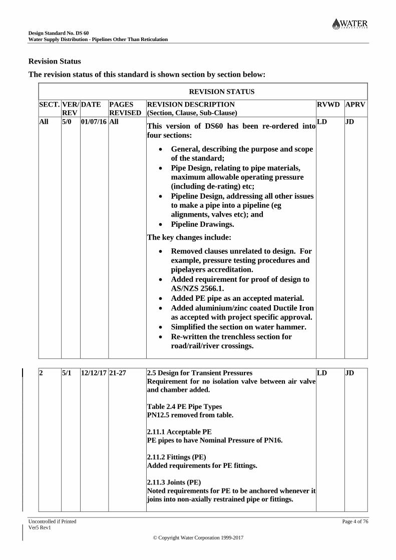
Revision Status
The revision status of this standard is shown section by section below:
REVISION STATUS
SECT. VER/
REV
DATE PAGES
REVISED
REVISION DESCRIPTION
(Section, Clause, Sub-Clause)
RVWD APRV
All 5/0 01/07/16 All This version of DS60 has been re-ordered into
four sections:
General, describing the purpose and scope
of the standard;
Pipe Design, relating to pipe materials,
maximum allowable operating pressure
(including de-rating) etc;
Pipeline Design, addressing all other issues
to make a pipe into a pipeline (eg
alignments, valves etc); and
Pipeline Drawings.
The key changes include:
Removed clauses unrelated to design. For
example, pressure testing procedures and
pipelayers accreditation.
Added requirement for proof of design to
AS/NZS 2566.1.
Added PE pipe as an accepted material.
Added aluminium/zinc coated Ductile Iron
as accepted with project specific approval.
Simplified the section on water hammer.
Re-written the trenchless section for
road/rail/river crossings.
LD JD
2 5/1 12/12/17 21-27 2.5 Design for Transient Pressures
Requirement for no isolation valve between air valve
and chamber added.
Table 2.4 PE Pipe Types
PN12.5 removed from table.
2.11.1 Acceptable PE
PE pipes to have Nominal Pressure of PN16.
2.11.2 Fittings (PE)
Added requirements for PE fittings.
2.11.3 Joints (PE)
Noted requirements for PE to be anchored whenever it
joins into non-axially restrained pipe or fittings.
LD JD

Design Standard No. DS 60
Water Supply Distribution - Pipelines Other Than Reticulation
Uncontrolled if Printed Page 5 of 76 Ver5 Rev1
© Copyright Water Corporation 1999-2017
Table 2.7 Pressure and Diameter range for use of
Sintalock RRJ-WR pipe updated.
3 5/1 12/12/17 40-67 3.4 Clearances
Clarified.
3.6.1 Table outlining the expectations of designers and
tenderers added for Horizontal Directional Drilling.
3.6.2 No Encasement Pipe Installations
Added requirement for PE used for directional drilling
to have a resistance to slow crack growth.
3.6.3 Encasement Pipe with an Un-grouted Anulus
Clarified spacer requirements.
3.7.2 Trench Excavation, Pipe Embedment and
Backfill
Clarified expectations of designers where native
backfill is >12% fines.
3.7.4.1 Requirements for Restricted Access Steel
Pipelines clause added.
3.9.3.1 Concrete Supports for MSCL Pipelines
Revised. Added diagram to show sacrificial saddle.
3.10.2.5 Size (Section and Isolating Valves)
Added requirement to check hydraulic implications.
3.10.6 Scour Valves
Section revised and updated.
LD JD
4 5/1 12/12/17 75-78 4.1 Design Drawings
Added requirement for test pressure to be on drawing.
4.5 Longitudinal Sections
Added requirement for co-ordinates of appurtenances
to be on long sections.
LD JD

Design Standard No. DS 60
Water Supply Distribution - Pipelines Other Than Reticulation
Uncontrolled if Printed Page 6 of 76 Ver5 Rev1
© Copyright Water Corporation 1999-2017
DESIGN STANDARD DS 60 Water Supple Distribution – Pipelines Other Than Reticulation
CONTENTS
Section Page
1 GENERAL 10 Purpose .......................................................................................................................................................... 10 1.1
Scope ............................................................................................................................................................. 10 1.2
Occupation Safety and Health ...................................................................................................................... 10 1.3
Engineering Design Process ......................................................................................................................... 11 1.4
Reference Documents ................................................................................................................................... 11 1.5
Definitions and Abbreviations ...................................................................................................................... 13 1.6
Acceptance of Materials ............................................................................................................................... 14 1.7
2 PIPE DESIGN 16 Selection Factors ........................................................................................................................................... 16 2.1
Acceptable Pipe Material ............................................................................................................................. 16 2.2
Pipe Structural Design .................................................................................................................................. 16 2.3
Maximum Allowable Operating Pressures .................................................................................................. 16 2.4
Design for Transient Pressures ..................................................................................................................... 17 2.5
Fatigue De-rating of Plastic Pipes and Fittings ............................................................................................ 18 2.6
Temperature De-rating of Plastic Pipes and Fittings ................................................................................... 19 2.7
Thermal Effect and Shortening due to Pressurization ................................................................................. 19 2.8
Plastic Pipeline Component Minimum Pressure Class ................................................................................ 19 2.9
Polyvinylchloride (PVC) .............................................................................................................................. 20 2.10
Acceptable PVC Pipe ................................................................................................................... 20 2.10.1
Fittings .......................................................................................................................................... 20 2.10.2
Pipeline Joints ............................................................................................................................... 20 2.10.3
De-rating ....................................................................................................................................... 21 2.10.4
Ground Conditions ....................................................................................................................... 21 2.10.5
UV Exposure ................................................................................................................................ 21 2.10.6
Considerations in PVC Application ............................................................................................. 21 2.10.7
Polyethylene (PE) ......................................................................................................................................... 22 2.11
Acceptable PE Pipe ...................................................................................................................... 22 2.11.1
Fittings .......................................................................................................................................... 22 2.11.2
Joints ............................................................................................................................................. 23 2.11.3
De-Rating ...................................................................................................................................... 23 2.11.4
Ground Conditions ....................................................................................................................... 23 2.11.5
Considerations in PE Application ................................................................................................ 23 2.11.6
Steel (S or MSCL) ........................................................................................................................................ 23 2.12
Application of Steel Pipes ............................................................................................................ 23 2.12.1
Manufacture .................................................................................................................................. 23 2.12.2
External Coating – Buried and Above Ground Pipework ........................................................... 24 2.12.3
External Coating – Miscellaneous Pipework Configuration ....................................................... 24 2.12.4

Design Standard No. DS 60
Water Supply Distribution - Pipelines Other Than Reticulation
Uncontrolled if Printed Page 7 of 76 Ver5 Rev1
© Copyright Water Corporation 1999-2017
Joint Types and Allowable Joint Deflection ................................................................................ 24 2.12.5
Joint Selection ............................................................................................................................... 26 2.12.6
Ring Deflection ............................................................................................................................. 27 2.12.7
Fittings .......................................................................................................................................... 27 2.12.8
Jointing and Plate Thickness ........................................................................................................ 28 2.12.9
Design Criteria for Finite Element Analysis (FEA), for Intrados Banded Fabricated Bends .... 28 2.12.10
Considerations in MSCL Application .......................................................................................... 31 2.12.11
Ductile Iron (DI) ........................................................................................................................................... 31 2.13
Acceptability ................................................................................................................................. 31 2.13.1
3 PIPELINE DESIGN 32 Design Considerations .................................................................................................................................. 32 3.1
Operational Life ............................................................................................................................ 32 3.1.1
Determination of Pipe Diameters ................................................................................................. 32 3.1.2
Design Flow Velocity and Head Loss ......................................................................................... 32 3.1.3
Material Choice ............................................................................................................................ 32 3.1.4
Voltage Mitigation ........................................................................................................................ 33 3.1.5
Other Considerations .................................................................................................................... 33 3.1.6
Routes and Alignments ................................................................................................................................. 33 3.2
Routes ........................................................................................................................................... 33 3.2.1
Alignments .................................................................................................................................... 34 3.2.2
Depths/Cover ................................................................................................................................................ 35 3.3
Clearances ..................................................................................................................................................... 36 3.4
Horizontal Clearances .................................................................................................................. 36 3.4.1
Vertical Clearances ....................................................................................................................... 36 3.4.2
Grade ............................................................................................................................................................. 37 3.5
Road/Rail/River Crossing ............................................................................................................................. 37 3.6
General .......................................................................................................................................... 37 3.6.1
No Encasement Pipe Installations ................................................................................................ 38 3.6.2
Encasement Pipe with an Un-grouted Annulus ........................................................................... 39 3.6.3
Encasement Pipe with a Fully Grouted Annulus ......................................................................... 39 3.6.4
Installation Requirements ............................................................................................................. 41 3.6.5
Major Road Crossings .................................................................................................................. 42 3.6.6
Railway Crossings ........................................................................................................................ 42 3.6.7
Bridge Crossings ........................................................................................................................... 42 3.6.8
Drain/River Crossings .................................................................................................................. 42 3.6.9
Below Ground Pipelines ............................................................................................................................... 42 3.7
Reasons for Laying Pipe below Ground ...................................................................................... 42 3.7.1
Trench Excavation, Pipe Embedment and Backfill ..................................................................... 42 3.7.2
Trench stops .................................................................................................................................. 43 3.7.3
Design Standard No. DS 60
Water Supply Distribution - Pipelines Other Than Reticulation
Uncontrolled if Printed Page 8 of 76 Ver5 Rev1
© Copyright Water Corporation 1999-2017
Steel Pipelines ............................................................................................................................... 43 3.7.4
Anchorage of Buried Pipelines..................................................................................................................... 44 3.8
Thrust ............................................................................................................................................ 44 3.8.1
Thrust Restraint ............................................................................................................................ 44 3.8.2
Anchorage on Steep Slopes .......................................................................................................... 47 3.8.3
Marker Posts and Gates ................................................................................................................ 47 3.8.4
Tracer Tape ................................................................................................................................... 47 3.8.5
Connections to Distribution and Reticulation Mains .................................................................. 47 3.8.6
Above Ground Pipelines ............................................................................................................................... 48 3.9
Reasons for laying pipe above ground ......................................................................................... 48 3.9.1
Pipe Type ...................................................................................................................................... 49 3.9.2
Pipe Supports ................................................................................................................................ 49 3.9.3
Deficient Pipe Supports ................................................................................................................ 50 3.9.4
Pipe Anchorage ............................................................................................................................. 50 3.9.5
Other Requirements ...................................................................................................................... 50 3.9.6
Valves ............................................................................................................................................................ 50 3.10
Valve Types, Uses and Installation .............................................................................................. 50 3.10.1
Section and Isolating Valves ........................................................................................................ 52 3.10.2
Bypass Arrangements ................................................................................................................... 54 3.10.3
Non-Return Valves ....................................................................................................................... 54 3.10.4
Air Valves ..................................................................................................................................... 54 3.10.5
Scour Valves ................................................................................................................................. 58 3.10.6
Pressure Reducing and Pressure Sustaining Valves .................................................................... 60 3.10.7
Flow Regulating Valves ............................................................................................................... 62 3.10.8
Valve Pits ...................................................................................................................................................... 62 3.11
Purpose .......................................................................................................................................... 62 3.11.1
Type .............................................................................................................................................. 63 3.11.2
Location ........................................................................................................................................ 63 3.11.3
Loading ......................................................................................................................................... 63 3.11.4
Anchoring Pipework ..................................................................................................................... 64 3.11.5
Buoyancy ...................................................................................................................................... 64 3.11.6
Valve Supports.............................................................................................................................. 64 3.11.7
Pit Access Clearances ................................................................................................................... 64 3.11.8
Pit Drainage .................................................................................................................................. 65 3.11.9
Ladders, Stairs and Platforms ....................................................................................................... 65 3.11.10
Pit Covers and Edge Protection .................................................................................................... 65 3.11.11
Earthing Systems .......................................................................................................................... 65 3.11.12
Flow Measurement ....................................................................................................................................... 65 3.12

Design Standard No. DS 60
Water Supply Distribution - Pipelines Other Than Reticulation
Uncontrolled if Printed Page 9 of 76 Ver5 Rev1
© Copyright Water Corporation 1999-2017
Purpose .......................................................................................................................................... 65 3.12.1
Types of Meters ............................................................................................................................ 66 3.12.2
Electromagnetic Flowmeter Installation ...................................................................................... 66 3.12.3
Pitometers ..................................................................................................................................... 66 3.12.4
Sampling and Tapping Points ....................................................................................................................... 67 3.13
Functional Requirements for Water Sampling ............................................................................ 67 3.13.1
Tapping points .............................................................................................................................. 67 3.13.2
Manual Sampling Point ................................................................................................................ 67 3.13.3
Analyser Sampling Point .............................................................................................................. 67 3.13.4
Manhole Entry into Pipelines ....................................................................................................................... 68 3.14
Purpose .......................................................................................................................................... 68 3.14.1
Size ................................................................................................................................................ 68 3.14.2
Location ........................................................................................................................................ 68 3.14.3
Installation..................................................................................................................................... 68 3.14.4
Flanged Joints ............................................................................................................................................... 68 3.15
Termination of Pipelines .............................................................................................................................. 69 3.16
4 PIPELINE DRAWINGS 70 Design Drawings .......................................................................................................................................... 70 4.1
Drafting Details for Design Drawings ......................................................................................................... 70 4.2
Scales ............................................................................................................................................ 70 4.2.1
Notation......................................................................................................................................... 70 4.2.2
Pipe Route Surveys ....................................................................................................................................... 72 4.3
Basis of Survey ............................................................................................................................. 72 4.3.1
Presentation Standard ................................................................................................................... 73 4.3.2
Survey Pegs .................................................................................................................................. 73 4.3.3
Route Plans ................................................................................................................................................... 73 4.4
Longitudinal Sections ................................................................................................................................... 73 4.5
Design Standard No. DS 60
Water Supply Distribution - Pipelines Other Than Reticulation
Uncontrolled if Printed Page 10 of 76 Ver5 Rev1
© Copyright Water Corporation 1999-2017
1 GENERAL
Purpose 1.1
This design standard is intended to provide guidelines for the design and construction of
pipelines to be taken over or operated by the Water Corporation.
The requirements are based on operation, safety, maintenance, water quality, durability and
value for money considerations.
The Corporation’s regions may have additional or specific requirements for their pipelines.
These need to be identified on a case by case basis.
This part of the Standard shall be read in conjunction with the Water Supply Distribution –
Pipelines other than reticulation - Drawings.
Scope 1.2
This design standard addresses issues for drinking water conveyance pipelines as referred to
below:
a) Distribution Main – a pipeline which is a feeder to a reticulation network (normally DN
300 and larger, however smaller distribution mains may be applicable for small towns);
b) Outlet Main – an outlet from a storage that generally supplies distribution mains;
c) Supply Main – a pipeline generally smaller than DN 700 that supplies water from a
source;
d) Trunk Main – a pipeline, normally DN 500 or larger, that supplies water generally from
a major source to a major storage;
e) Rising or Pumping Main – a pipeline used essentially as a pump delivery line to another
system or storage;
f) Transfer Main – a pipeline used to transfer water from one system, source or storage to
another.
This design standard is not applicable to the following:
a) Pipelines that are not normally full and pressurised, for example pumped mains that
drain and refill during normal operations, drainage or irrigation pipelines;
b) Pipelines which have standard water services connected. For requirements on
subdivision reticulation pipelines of DN 250 and smaller refer to the Corporation’s
Water Reticulation Standard - DS 63;
c) Rural Water Strategy or similar low budget pipelines which provide non-standard levels
of service;
d) Pipelines within Water Treatment Plants.
This design standard has limited application to bore collector mains, which have additional
considerations for issues such as pigging the mains, for preventing air entrainment or allowing
air release after pump startup.
Occupation Safety and Health 1.3
Legislation compels employers and employees to follow safe practices regarding health and
safety in the workplace. Accordingly, all assets shall be designed to facilitate safe operational
and maintenance practices.

Design Standard No. DS 60
Water Supply Distribution - Pipelines Other Than Reticulation
Uncontrolled if Printed Page 11 of 76 Ver5 Rev1
© Copyright Water Corporation 1999-2017
Prior to 1985 bitumen tape wrap pipe system had been used. As some of these pipe wrapping
materials have been found to contain asbestos fibres (hazardous material), all procedure
regarding the removal, handling and disposal of pipe coatings containing asbestos shall be in
accordance with the relevant Water Corporation OSH Procedures and the Code of Practice for
the management and Control of Asbestos in Workplaces.
The Corporations Safety in Design (SID) process as outlined in the Engineering Design Process
and the Corporations OHS procedures, policies and requirements are in addition to any
requirements noted in this design standard.
Engineering Design Process 1.4
The Corporation’s Engineering Design Manual shall be used in the design of Water
Corporation’s engineering assets. The manual describes the roles of the Corporation’s Design
Manager and Designer in the design process and provides or references:
a) Design process guidance notes
b) Templates for process documents and design outputs
Any submission of design work to the Water Corporation shall be carried out and delivered in
accordance with the current Engineering Design Manual as agreed with the Water
Corporation’s design representative. Design work shall not be delegated to equipment suppliers
or other contractors. For issue of Engineering Design Manual and associated documents email
request to [email protected]
Reference Documents 1.5
AS
AS 1210 ........................ Pressure vessels
AS 1281 ........................ Cement mortar lining of steel pipes and fittings
AS 1579 ........................ Arc-welded steel pipes and fittings for water and waste-water
AS 1646 ........................ Elastomeric seals for waterworks purposes
AS 2129 ........................ Flanges for pipes, valves and fittings
AS 3996 ........................ Access covers and grates
AS 4041 ........................ Pressure piping
AS 4321 ........................ Fusion-bonded medium-density polyethylene coating and lining for
pipes and fittings
AS 4799 ........................ Installation of underground utility services and pipelines within railway
boundaries
AS/NZS
AS/NZS 1365 ............... Tolerances for flat-rolled steel products
AS/NZS 1477 ............... PVC pipes and fittings for pressure applications
AS/NZS 2280 ............... Ductile iron pipes and fittings
AS/NZS 2566.1 ............ Buried flexible pipelines - Structural design
AS/NZS 2566.2 ............ Buried flexible pipelines - Installation

Design Standard No. DS 60
Water Supply Distribution - Pipelines Other Than Reticulation
Uncontrolled if Printed Page 12 of 76 Ver5 Rev1
© Copyright Water Corporation 1999-2017
AS/NZS 4020 ............... Testing of products for use in contact with drinking water
AS/NZS 4087 ............... Metallic flanges for waterworks purposes
AS/NZS 4129 ............... Fittings for polyethylene (PE) pipes for pressure applications
AS/NZS 4130 ............... Polyethylene (PE) pipes for pressure applications
AS/NZS 4131 ............... Polyethylene (PE) compounds for pressure pipes and fittings
AS/NZS 4158 ............... Thermal-bonded polymeric coatings on valves and fittings for water
industry purposes
AS/NZS 4331.1 ............ Metallic flanges - Steel flanges
AS/NZS 4331.2 ............ Metallic flanges - Cast iron flanges
AS/NZS 4331.3 ............ Metallic flanges - Copper alloy and composite flanges
AS/NZS 4765 ............... Modified PVC (PVC-M) pipes for pressure applications
AS/NZS 4998 ............... Bolted unrestrained mechanical coupling for waterworks purposes
Water Corporation Documents
DS23 ............................. Pipeline AC interference and substation earthing
DS25-01 ....................... Field instrumentation
DS31-01 ....................... Pipework - mechanical
DS31-02 ....................... Valves and appurtenances - mechanical
DS38-02 ....................... Flanged connections
DS62 ............................. Site Security Treatments
DS63 ............................. Water reticulation pipelines DN 250 and smaller
DS65 ............................. Pipe fittings standard drawings
DS80 ............................. WCX CAD Standard
DS91 ............................. Cathodic protection standard
DS95 ............................. Standard for the selection, preparation, application, inspection and
testing of protective coatings on water corporation assets. Includes B1 -
Inorganic Zinc Silicate Coating on Steel or Cast Iron and M8 - Cement
Mortar Lining Requirement.
SPS 100 ........................ Steel pipe for waterworks purposes
SPS 106 ........................ Ductile Iron Pipe Fittings for Pressure Applications
SPS 116 ........................ Modified Polyvinylchloride – PVC-M – Pipe for Pressure Applications
SPS 125 ........................ Polyethylene and Polypropylene Pipe and Pipe Fittings
WS-1 ............................ Welding specification metal arc welding
WS-2 ............................ Welding joining specification thermoplastics
S151 .............................. Prevention of falls
PIPA (Plastics Industry Pipe Association of Australia)
PIPA Guideline POP006 ............ Derating requirements for fittings
Design Standard No. DS 60
Water Supply Distribution - Pipelines Other Than Reticulation
Uncontrolled if Printed Page 13 of 76 Ver5 Rev1
© Copyright Water Corporation 1999-2017
PIPA Guideline POP007 ............ Metal Backing Flanges For Use with Polyethylene (PE) Pipe
Flange Adaptors
PIPA Guideline POP010A ......... Part 1: Polyethylene pressure pipes design for dynamic
stresses
PIPA Guideline POP010B .......... Part 2: Fusion fittings for use with polyethylene pressure pipes
design for dynamic stresses
PIPA Guideline POP016 ............ High stress crack resistant PE100
PIPA Guideline POP101 ............ PVC Pressure pipes design for dynamic stresses
Other References
Austroads Bridge Design Specification
Criteria for regulated water supply (August 2004)
Engineering Design Process Manual
Utility Providers Code of Practice for Western Australia
American Water Works Association M11 Steel Pipe: A Guide for Design and Installation
MRWA Functional Road Hierarchy
DIN PAS 1075 Pipes made from polyethylene for alternative installation techniques –
dimension, technical requirements and testing
Definitions and Abbreviations 1.6
Standard Drawing: ................. A drawing that shows exactly how to construct something. No
changes should be made.
Example Drawing: ................. Shows a preferred arrangement. Minimum design requirements
are shown. The suitability of the example requires checking and
modifying for the site specific application.
AHBP ..................................... Allowable Horizontal Bearing Pressure
AOP ........................................ Allowable Operation Pressure
ARI ......................................... Average Recurrence Interval
CP ........................................... Cathodic Protection
CSE......................................... Confined Space Entry
DAV ....................................... Double Air Valve
DCVG .................................... Direct Current Voltage Gradient
DI ............................................ Ductile Iron
DN .......................................... Nominal Diameter
EPDM ..................................... Ethylene Propylene Diene Monomer is a type of synthetic rubber
used in seals.
ESJ .......................................... Elastomeric Seal Joint
FEA ........................................ Finite Element Analysis
FRP ......................................... Fibre Reinforced Polymer

Design Standard No. DS 60
Water Supply Distribution - Pipelines Other Than Reticulation
Uncontrolled if Printed Page 14 of 76 Ver5 Rev1
© Copyright Water Corporation 1999-2017
FSL ......................................... Finished Surface Level
GRP ........................................ Glass fibre Reinforced Polymer
IZS .......................................... Inorganic Zinc Silicate
MAOP .................................... Maximum Allowable Operating Pressure
M-PVC ................................... Modified Polyvinyl Chloride
MRWA ................................... Main Roads Western Australia
MSCL ..................................... Mild Steel Cement Lined
NBR ........................................ Acrylonitrile Butadiene Rubber is a type of synthetic rubber used
in seals.
O-PVC .................................... Oriented Polyvinyl Chloride
PE ........................................... Polyethylene
PIPA ....................................... The Plastics Industry Pipe Association of Australia
PN ........................................... Nominal Pressure
PoF ......................................... Prevention of Falls
PRV ........................................ Pressure Reducing Valve
PSV......................................... Pressure Sustaining Valve
RRJ ......................................... Rubber Ring Joint
RRJ-WR ................................. Rubber Ring Joint – Welded Restraint
S .............................................. Steel
SCADA .................................. Supervisory Control and Data Acquisition
SEAA ..................................... Safety, Environment & Aboriginal Affairs
SID ......................................... Safety in Design
SPS ......................................... Strategic Product Specification
SSSI ........................................ Surveying & Spatial Sciences Institute
U-PVC .................................... Unplasticised Polyvinyl Chloride
WJ ........................................... Welded Joint
Acceptance of Materials 1.7
All materials or components shall comply with the relevant Water Corporation’s Strategic
Product Specification (SPS), or where a SPS is not applicable, the latest edition of the relevant
Australian Standard. The Corporation may require, from time to time, manufacturers’
certificates, test results and guarantees. New pipes and fittings shall be used unless specifically
approved by the Corporation. Materials shall be handled in accordance with the manufacturer’s
specifications. Damaged material shall not be used.
Where a product is part of a product category maintained in the Water Corporation’s Strategic
Product Register, the product supplied shall be listed in the latest revision of the register and the
approval expiry date will not have passed by the product delivery date.
All materials or products which will be in contact with the water supply shall comply with
AS/NZS 4020. Wherever requested by the Corporation, documentary evidence of material or
product certification to AS/NZS 4020 shall be provided.

Design Standard No. DS 60
Water Supply Distribution - Pipelines Other Than Reticulation
Uncontrolled if Printed Page 15 of 76 Ver5 Rev1
© Copyright Water Corporation 1999-2017
The Corporation retains the right, for commercial, logistic or any other reason, not to accept any
material or component.

Design Standard No. DS 60
Water Supply Distribution - Pipelines Other Than Reticulation
Uncontrolled if Printed Page 16 of 76 Ver5 Rev1
© Copyright Water Corporation 1999-2017
2 PIPE DESIGN
Selection Factors 2.1
The choice of pipe material depends upon many design factors which are listed in the Pipeline
Design section.
Acceptable Pipe Material 2.2
The following materials are currently acceptable:
a) Polyvinylchloride, Modified (PVC-M)
b) Polyethylene (PE)
c) Steel (S) or Mild Steel Cement Lined (MSCL)
The following materials are not frequently used and require specific project by project
acceptance:
a) Polyvinylchloride, Oriented (PVC-O)
b) Glass/Fibre Reinforced Plastic (GRP/FRP)
c) Zinc/Aluminum or PE coated Ductile Iron (DI)
The following materials are generally not acceptable:
a) Uncoated Ductile Iron
Pipe Structural Design 2.3
Pipelines shall be designed to withstand all the forces and load combinations to which they may
be exposed including internal forces, external forces, temperature effects and settlement.
The design of buried flexible pipelines shall be in accordance with AS/NZS 2566.1.
For pipeline conditions where any of the following apply, a summary of the design and
outcomes shall be included in the design summary report.
a) Native soil is other than sand;
b) Embedment material is other than sand;
c) Proposed cover is less than, or more than specified in this standard;
d) Under pavements where the loading is or may be greater than normal highway loading;
e) The compaction of the embedment material cannot be controlled or confirmed (including
installation by horizontal directional drilling)
f) Construction loads, other than for construction of the embedment and trenchfill, will be
imposed over the pipe.
In no case shall the pipe PN rating or its equivalent corresponding stiffness, be less than
otherwise required by this standard or the manufacturer’s recommendation. Sand is defined as
having less than 12% fines.
Maximum Allowable Operating Pressures 2.4
Maximum Allowable Operating Pressure (MAOP) is defined per AS/NZS 4087 as the
maximum internal pressure, including surge that a component can safely withstand in service.

Design Standard No. DS 60
Water Supply Distribution - Pipelines Other Than Reticulation
Uncontrolled if Printed Page 17 of 76 Ver5 Rev1
© Copyright Water Corporation 1999-2017
(ie. the maximum pressure to which a pipe or fitting may be subjected to under transient surge
conditions).
The pressure capacity of a pipeline system (sometimes called the system pressure rating or
pressure class) is generally defined by the lowest of the following:
a) The rated MAOP of the pipe, including applicable derating for temperature or fatigue
b) The AOP of the attached fittings including bends, tees, flanges, valves etc
c) The MAOP that can be safely held by the pipeline anchorage system
Pipeline systems have historically been set to standard system pressure capacity/rating of 120m,
140m, 210m or 350m.
Recent mild steel concrete lining (MSCL) systems have been designed for a 250m rating, which
aligns with the ISO PN 25 flange standard and is roughly equivalent to the MAOP of some
standard sized large diameter steel pipes.
A pressure rating of PN16 has replaced the historic PN14. PN16 aligns with the MAOP rating
of pipes currently manufactured to Australian Standards and with AS/NZS 4087 pipe flange
pressure ratings.
The design system pressure capacity (rating) is selected from the standard pressure ratings of
120m, 160m, 210m, 250m or 350m and to be greater than the current and planned future
operating pressures. Pipeline systems shall be at least PN12.
Note: The 120m rating is only a nominal for plastic pipelines. Although the system may
comprise PN 12 or 12.5 plastic pipe, PN 16 fittings and have suitable anchorage for 120m of
pressure, as the plastic pipe may require derating for temperature or fatigue, the 120m is only a
nominal system rating.
Standard pressure ratings for valves and flanges are PN 16, PN 21 and PN 35 to AS/NZS 4087
and PN 25 to AS/NZS 4331.
Where a section of a pipeline requires a higher pressure rating, the Water Corporation requires
all the pipeline, valves and fittings to be at higher rating for maintenance interchangeability.
The designer shall nominate the Maximum Allowable Operating Pressure and the System Test
Pressure on the drawings.
Design for Transient Pressures 2.5
Systems containing pumps or actuated control valves shall have a transient analysis undertaken
using Watham, Wanda or an equivalent program.
The analysis shall consider short and long term system conditions and shall determine the
protection devices and or valve operating times required to prevent the system MAOP being
exceeded and to prevent air entry into the pipeline. The results of the analysis shall be contained
in the design report.
The allowable methods of surge control include:
a) Surge vessels
b) Controlled pump start up and stopping times,
c) Controlled valve closing times.
d) For non-drinking water and negative surge, a bank of multiple and redundant air valves.
Note the mechanical design standards contain design requirements for these types of assets.
Design Standard No. DS 60
Water Supply Distribution - Pipelines Other Than Reticulation
Uncontrolled if Printed Page 18 of 76 Ver5 Rev1
© Copyright Water Corporation 1999-2017
One way surge tanks have historically been used for negative surge. However, due to the
unreliable operation of the seldom used non return valve and the potential to draw very old
water into the main, new systems should not use one way surge tanks.
Where air valves are permitted for negative surge control, the installed number of air valves
must be at least double the number of valves needed for surge control. This will allow up to
50% to be removed for maintenance at any time. Signage is required to inform operators that
the bank of valves is required for water hammer protection and at least 50% shall be operational
at all times.
In special cases, for drinking water and with project specific approval, where the allowable
methods of negative surge control are impractical, the use of an air chamber located above the
pipeline may be considered. The chamber is connected so that under normal operation
chlorinated water flushes through the chamber and is large enough to contain 1.5 times the air
volume that is predicted to be required during a negative surge. Multiple and redundant air
valves and signage is required. As the air valve is required to always allow air entry, there can
be no isolation valves between the air valve and the chamber.
The proposed transient protection shall be agreed with the Corporation prior to commencing
detailed design.
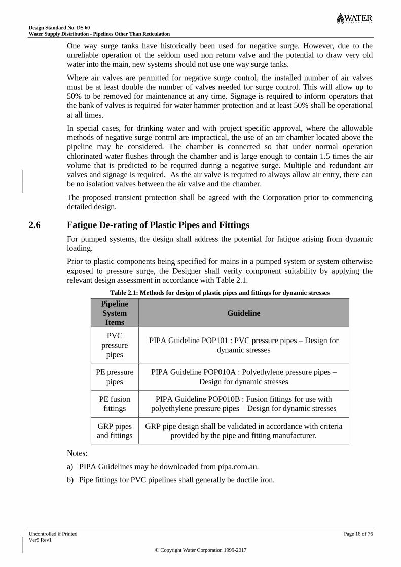
Fatigue De-rating of Plastic Pipes and Fittings 2.6
For pumped systems, the design shall address the potential for fatigue arising from dynamic
loading.
Prior to plastic components being specified for mains in a pumped system or system otherwise
exposed to pressure surge, the Designer shall verify component suitability by applying the
relevant design assessment in accordance with Table 2.1.
Table 2.1: Methods for design of plastic pipes and fittings for dynamic stresses
Pipeline
System
Items
Guideline
PVC
pressure
pipes
PIPA Guideline POP101 : PVC pressure pipes – Design for
dynamic stresses
PE pressure
pipes
PIPA Guideline POP010A : Polyethylene pressure pipes –
Design for dynamic stresses
PE fusion
fittings
PIPA Guideline POP010B : Fusion fittings for use with
polyethylene pressure pipes – Design for dynamic stresses
GRP pipes
and fittings
GRP pipe design shall be validated in accordance with criteria
provided by the pipe and fitting manufacturer.
Notes:
a) PIPA Guidelines may be downloaded from pipa.com.au.
b) Pipe fittings for PVC pipelines shall generally be ductile iron.
Design Standard No. DS 60
Water Supply Distribution - Pipelines Other Than Reticulation
Uncontrolled if Printed Page 19 of 76 Ver5 Rev1
© Copyright Water Corporation 1999-2017
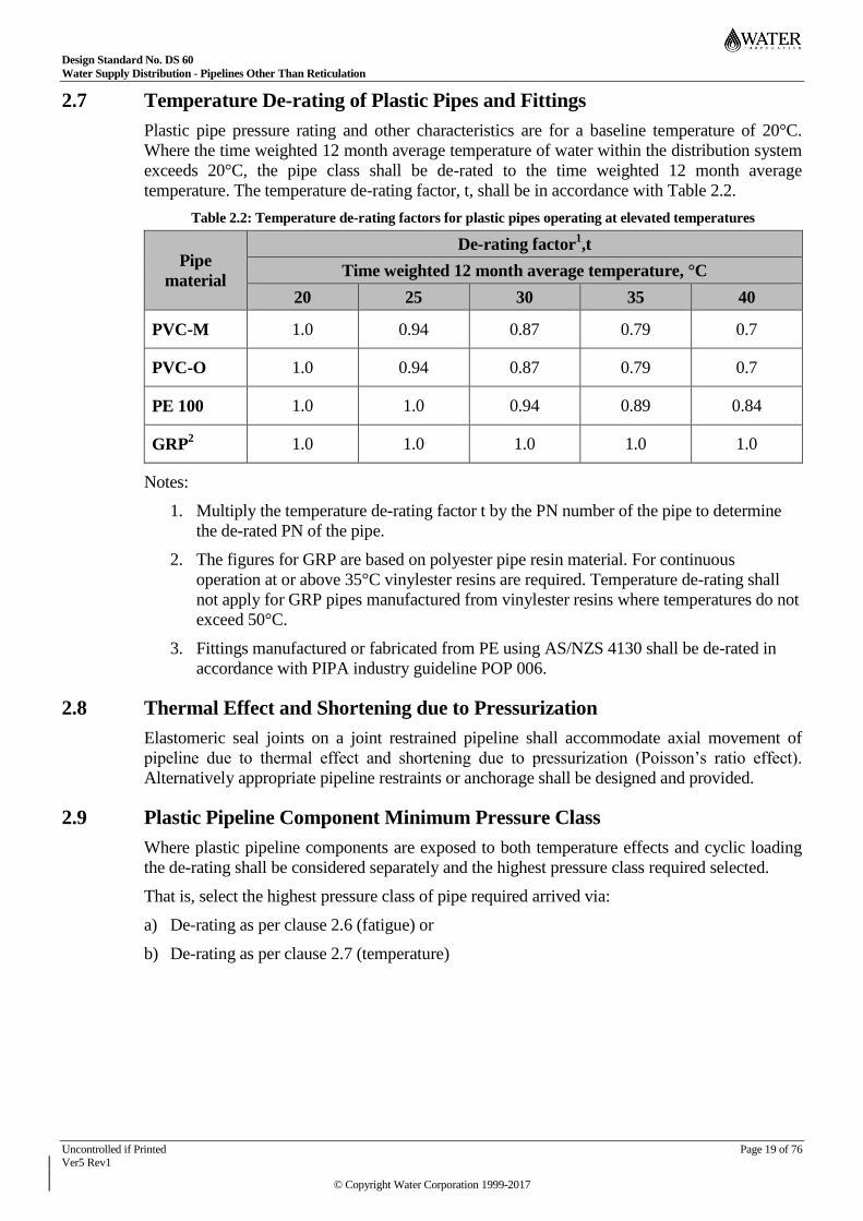
Temperature De-rating of Plastic Pipes and Fittings 2.7
Plastic pipe pressure rating and other characteristics are for a baseline temperature of 20°C.
Where the time weighted 12 month average temperature of water within the distribution system
exceeds 20°C, the pipe class shall be de-rated to the time weighted 12 month average
temperature. The temperature de-rating factor, t, shall be in accordance with Table 2.2.
Table 2.2: Temperature de-rating factors for plastic pipes operating at elevated temperatures
Pipe
material
De-rating factor1,t
Time weighted 12 month average temperature, °C
20 25 30 35 40
PVC-M 1.0 0.94 0.87 0.79 0.7
PVC-O 1.0 0.94 0.87 0.79 0.7
PE 100 1.0 1.0 0.94 0.89 0.84
GRP2 1.0 1.0 1.0 1.0 1.0
Notes:
1. Multiply the temperature de-rating factor t by the PN number of the pipe to determine
the de-rated PN of the pipe.
2. The figures for GRP are based on polyester pipe resin material. For continuous
operation at or above 35°C vinylester resins are required. Temperature de-rating shall
not apply for GRP pipes manufactured from vinylester resins where temperatures do not
exceed 50°C.
3. Fittings manufactured or fabricated from PE using AS/NZS 4130 shall be de-rated in
accordance with PIPA industry guideline POP 006.
Thermal Effect and Shortening due to Pressurization 2.8
Elastomeric seal joints on a joint restrained pipeline shall accommodate axial movement of
pipeline due to thermal effect and shortening due to pressurization (Poisson’s ratio effect).
Alternatively appropriate pipeline restraints or anchorage shall be designed and provided.
Plastic Pipeline Component Minimum Pressure Class 2.9
Where plastic pipeline components are exposed to both temperature effects and cyclic loading
the de-rating shall be considered separately and the highest pressure class required selected.
That is, select the highest pressure class of pipe required arrived via:
a) De-rating as per clause 2.6 (fatigue) or
b) De-rating as per clause 2.7 (temperature)

Design Standard No. DS 60
Water Supply Distribution - Pipelines Other Than Reticulation
Uncontrolled if Printed Page 20 of 76 Ver5 Rev1
© Copyright Water Corporation 1999-2017
Polyvinylchloride (PVC) 2.10
Acceptable PVC Pipe 2.10.1
The PVC pipe listed in Table 2.3 is acceptable to the Corporation.
Table 2.3: PVC Pipe Types
Materials
Nominal
Diameter
(DN)
Nominal
Pressure
(PN)
Maximum
Allowable
Operating
Pressure
(m)
Acceptable use
MPVC to
SPS116 and
AS/NZS 4765
Series 2
Up to and
including
DN375
12,16
120, 160
Below ground use only. Not to be
used in chemically contaminated
ground (esters, ketones, ethers and
aromatic or chlorinated
hydrocarbons). Not to be used
where exposed to UV radiation.
Generally not used for pipelines
subject to cyclic or high surges.
Notes:
a) Normal pipe lengths are 6m.
b) For pipes DN 250 and smaller refer to DS63.
c) Use of PN20 or OPVC or diameters greater than DN375 PVC pipes shall be subject to
acceptance of the Corporation.
Fittings 2.10.2
Pipe fittings for use with PVC pipe shall be socketed Ductile Iron fittings to SPS106 and
AS/NZS 2280. Spigoted Ductile Iron fittings shall not be permissible. All Ductile Iron fittings
shall be thermal-bond polymerically coated and lined to AS/NZS 4158.
Pipeline Joints 2.10.3
PVC pipes shall be in accordance with AS/NZS 4765, Series 2 with elastomeric seal joints.
Joint elastomeric seals shall be EPDM or NBR in accordance with AS 1646 and shall be
supplied by the pipe manufacturer.
The use of bolted (e.g. Gibault or Straub type) pipe couplings in new pipeline work shall not be
generally permissible in lieu of factory made pipe jointing systems. Where permitted, axially
bolted (gibault style) couplings shall comply with AS/NZS 4998 long series couplings and the
use of circumferentially bolted (Straub style) couplings shall be limited to straight (as distinct
from deflected) pipeline joints in order to take due account of the relatively shorter length of
this coupling style. The use of pipe couplings that provide axial restraint shall require
submission of a justified design and installation methodology proposal to the Corporation for
determination of acceptability in each case.
Note that the common gibault style couplings (e.g. Varigib) provide no axial joint restraint. E-
lip Seal style couplings (e.g. Straub, Teekay or Norma) have a double lip sealing gasket and are
available with or without axial restraint but can be subject to long delivery lead times.
Design Standard No. DS 60
Water Supply Distribution - Pipelines Other Than Reticulation
Uncontrolled if Printed Page 21 of 76 Ver5 Rev1
© Copyright Water Corporation 1999-2017
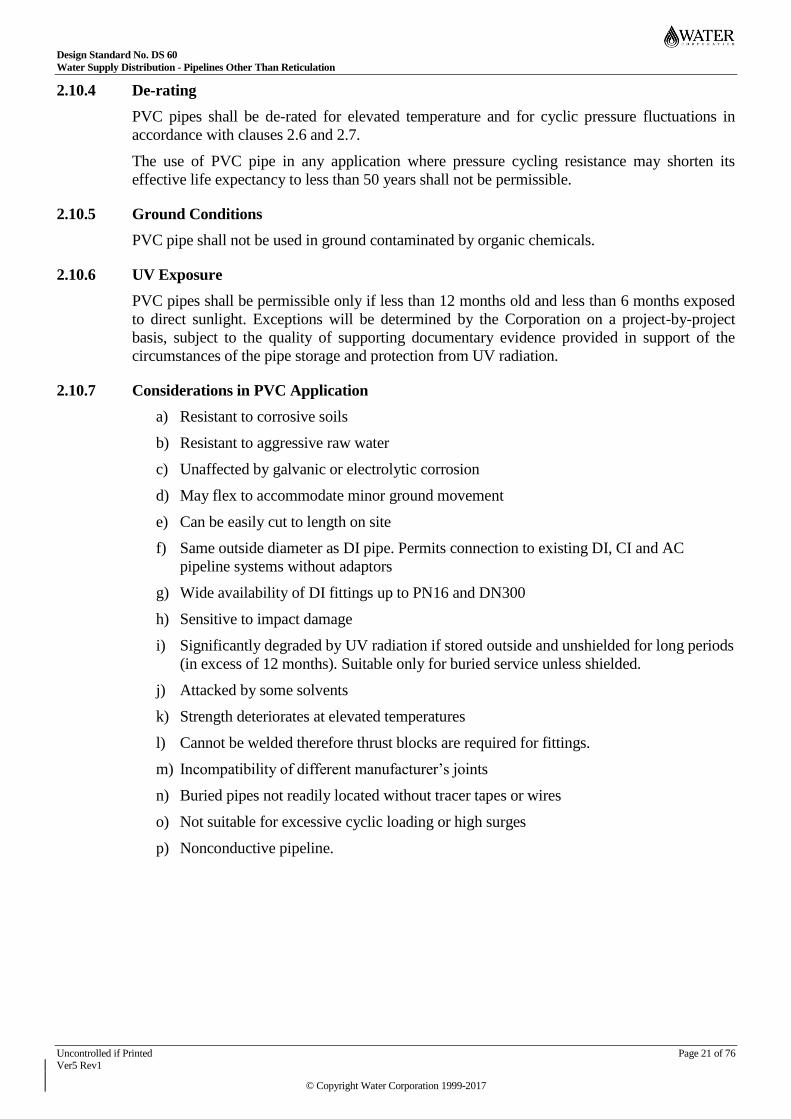
De-rating 2.10.4
PVC pipes shall be de-rated for elevated temperature and for cyclic pressure fluctuations in
accordance with clauses 2.6 and 2.7.
The use of PVC pipe in any application where pressure cycling resistance may shorten its
effective life expectancy to less than 50 years shall not be permissible.
Ground Conditions 2.10.5
PVC pipe shall not be used in ground contaminated by organic chemicals.
UV Exposure 2.10.6
PVC pipes shall be permissible only if less than 12 months old and less than 6 months exposed
to direct sunlight. Exceptions will be determined by the Corporation on a project-by-project
basis, subject to the quality of supporting documentary evidence provided in support of the
circumstances of the pipe storage and protection from UV radiation.
Considerations in PVC Application 2.10.7
a) Resistant to corrosive soils
b) Resistant to aggressive raw water
c) Unaffected by galvanic or electrolytic corrosion
d) May flex to accommodate minor ground movement
e) Can be easily cut to length on site
f) Same outside diameter as DI pipe. Permits connection to existing DI, CI and AC
pipeline systems without adaptors
g) Wide availability of DI fittings up to PN16 and DN300
h) Sensitive to impact damage
i) Significantly degraded by UV radiation if stored outside and unshielded for long periods
(in excess of 12 months). Suitable only for buried service unless shielded.
j) Attacked by some solvents
k) Strength deteriorates at elevated temperatures
l) Cannot be welded therefore thrust blocks are required for fittings.
m) Incompatibility of different manufacturer’s joints
n) Buried pipes not readily located without tracer tapes or wires
o) Not suitable for excessive cyclic loading or high surges
p) Nonconductive pipeline.
Design Standard No. DS 60
Water Supply Distribution - Pipelines Other Than Reticulation
Uncontrolled if Printed Page 22 of 76 Ver5 Rev1
© Copyright Water Corporation 1999-2017
Polyethylene (PE) 2.11
Acceptable PE Pipe 2.11.1
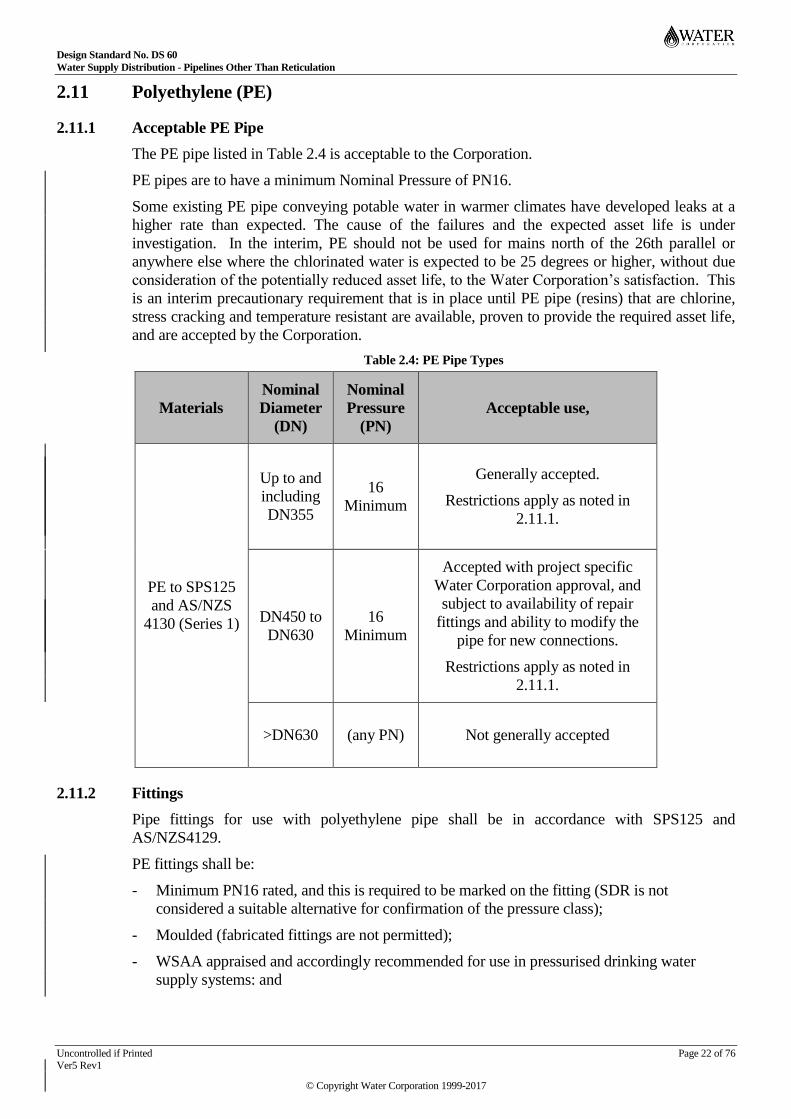
The PE pipe listed in Table 2.4 is acceptable to the Corporation.
PE pipes are to have a minimum Nominal Pressure of PN16.
Some existing PE pipe conveying potable water in warmer climates have developed leaks at a
higher rate than expected. The cause of the failures and the expected asset life is under
investigation. In the interim, PE should not be used for mains north of the 26th parallel or
anywhere else where the chlorinated water is expected to be 25 degrees or higher, without due
consideration of the potentially reduced asset life, to the Water Corporation’s satisfaction. This
is an interim precautionary requirement that is in place until PE pipe (resins) that are chlorine,
stress cracking and temperature resistant are available, proven to provide the required asset life,
and are accepted by the Corporation.
Table 2.4: PE Pipe Types
Materials
Nominal
Diameter
(DN)
Nominal
Pressure
(PN)
Acceptable use,
PE to SPS125
and AS/NZS
4130 (Series 1)
Up to and
including
DN355
16
Minimum
Generally accepted.
Restrictions apply as noted in
2.11.1.
DN450 to
DN630
16
Minimum
Accepted with project specific
Water Corporation approval, and
subject to availability of repair
fittings and ability to modify the
pipe for new connections.
Restrictions apply as noted in
2.11.1.
>DN630 (any PN) Not generally accepted
Fittings 2.11.2
Pipe fittings for use with polyethylene pipe shall be in accordance with SPS125 and
AS/NZS4129.
PE fittings shall be:
- Minimum PN16 rated, and this is required to be marked on the fitting (SDR is not
considered a suitable alternative for confirmation of the pressure class);
- Moulded (fabricated fittings are not permitted);
- WSAA appraised and accordingly recommended for use in pressurised drinking water
supply systems: and

Design Standard No. DS 60
Water Supply Distribution - Pipelines Other Than Reticulation
Uncontrolled if Printed Page 23 of 76 Ver5 Rev1
© Copyright Water Corporation 1999-2017
- Able to demonstrate enhanced resistance to slow-crack growth in excess of the performance
as stated in AS4131 (eg, HSCR as defined by PIPA POP16 or PE100-RC as defined by
DIN PAS 1075).
Joints 2.11.3
The jointing of pipes shall be in accordance with Clause 5.4 of WS-2.
PE stub flanges and backing rings shall comply with PIPA Guideline POP007.
PE shall be anchored wherever it joins into non-axially restrained pipe or fittings.
De-Rating 2.11.4
PE pipes shall be de-rated for elevated temperatures and for cyclic pressure fluctuations in
accordance with clauses 2.6 and 2.7.
Ground Conditions 2.11.5
PE pipe and fittings shall not be permissible in ground contaminated by organic chemicals.
Considerations in PE Application 2.11.6
a) Resistant to corrosive soils.
b) Resistant to aggressive water.
c) Unaffected by galvanic corrosion.
d) Will flex to accommodate large ground movement or subsidence.
e) Can be laid on a curve.
f) Can be easily cut to length on site.
g) Can be welded therefore use of thrust blocks at fittings can be avoided.
h) Significantly degraded by UV radiation if stored outside and unshielded for long periods (in
excess of 12 months). Suitable only for buried service unless shielded.
i) Attacked by some solvents.
j) Fusion jointing requires skilled installers and special equipment.
k) Buried pipes not readily located without tracer tapes or wires.
l) Retrospective installation of fittings/repair complicated.
m) Nonconductive pipeline.
n) Difficult construction where multiple existing services cross the trench.
Steel (S or MSCL) 2.12
Application of Steel Pipes 2.12.1
Steel pipes are generally used for most pipelines DN 600 and larger, and often for sizes smaller
than DN 600. Steel pipes are suitable for above or below ground use. Note that for extremely
corrosive environments, large diameter plastic pipe has been used.
Manufacture 2.12.2
Pipes shall be manufactured in accordance with SPS 100. These pipes are externally coated with
fusion-bonded medium density polyethylene and internally lined with cement mortar.

Design Standard No. DS 60
Water Supply Distribution - Pipelines Other Than Reticulation
Uncontrolled if Printed Page 24 of 76 Ver5 Rev1
© Copyright Water Corporation 1999-2017
“Sintalined” pipes, which are externally and internally coated with fusion-bonded medium
density polyethylene have yet to be commercially viable for acceptance by the Water
Corporation for water supply pipelines. (Steel pipe OD’s are not compatible with PVC, PE or
DI). Sintalined pipes may be accepted on a project specific basis where approval has been
obtained from the Corporation.
External Coating – Buried and Above Ground Pipework 2.12.3
External coating of pipework buried in soil and above ground shall be coated in accordance
with Section 13.0 of Water Corporation Design Standard DS95.
External Coating – Miscellaneous Pipework Configuration 2.12.4
External coating of miscellaneous pipework configuration such as below ground to above
ground transitions, joints with couplings and concrete interface shall be coated in accordance
with Section 13.0 of Water Corporation Design Standard DS95.
Joint Types and Allowable Joint Deflection 2.12.5
RING SEAL JOINTED
RRJ, Even though rubber rings have been replaced with EPDM seals, the abbreviation RRJ has
become entrenched as the short name for ring sealed pipes. The abbreviation RRJ is the
preferred terminology for ring seal jointed pipes in preference to the sometimes used ESJ
(elastomeric seal joint).
According to steel pipe manufacturer’s design manuals, RRJ allows an angular deflection of up
to approximately 3° depending on the pipe diameter; however, for all Water Corporation’s
projects, the design angular deflection at any RRJ shall be limited to 2/3 of the allowable
angular deflection specified by the manufacturer.
Figure 2.1: Example of RRJ Ring Jointed pipe
WELDED JOINT
WJ, Welded Joint. WJ is the preferred abbreviation for welded joint pipe. Non preferred
abbreviations that have been sometimes used include Banded Joint Welding, SSJ (Spherical
Slip in Joint), E&C (expanded and collapsed) or SIJ (Slip in jointed).

Design Standard No. DS 60
Water Supply Distribution - Pipelines Other Than Reticulation
Uncontrolled if Printed Page 25 of 76 Ver5 Rev1
© Copyright Water Corporation 1999-2017
Figure 2.2: Examples of Typical Manufacturer WJ Welded Joint Pipe.
WJ – PE is the preferred notation for Welded Joint Pipe with Plain Ends.
WJ – SSJ is the preferred notation for Welded Joint Pipe with Slip in Joints (or expanded and
collapsed or spherical slip in joints). The allowable angular deflection specified by steel pipe
manufacturers is as shown in Table 2.5 below.
Table 2.5: Maximum Allowable Angular Deflection for WJ-SSJ (Joints)
Pipe DN Angular deflection in
degrees
100 2.4
150 – 1200 3.0
1400 2.8
The maximum allowable angular deflection for a banded joint is as shown in Table 2.6 below.
Refer to the Corporation’s Pipe Fittings Standard Drawing AY58-19-1 for a banded joint detail.
Table 2.6: Maximum Allowable Angular Deflection for Banded Joints
Pipe DN Angular Deflection angle in
degrees
100 – 800 10 Degree
>800 6 Degree
RING SEAL JOINTED WITH WELDED RESTRAINT
RRJ-WR is the preferred abbreviation for joints that are Ring jointed and also have welded
restraint. Sintalock® (owned by Tyco/Tubemakers/Steelmain) is a brand of RRJ-WR pipe.

Design Standard No. DS 60
Water Supply Distribution - Pipelines Other Than Reticulation
Uncontrolled if Printed Page 26 of 76 Ver5 Rev1
© Copyright Water Corporation 1999-2017
Figure 2.3: Sintalock® Ring seal joint with Welded Restraint, RRJ-WR
Allowable angular deflection of RRJ-WR needs to be confirmed with the MSCL Pipe
Supplier’s recommendations. In general the allowable deflection is 1.1°.
As RRJ-WR has only a single external weld, it does not have the same MAOP as either RRJ or
WJ pipe. Hence the use of RRJ-WR pipe is to be limited as shown in Table 2.7.
Table 2.7: Pressure and Diameter range for use of Sintalock® RRJ-WR pipe
Sintalock ® RRJ-WR pipe PN 16 Application PN 21 Application
Minimum Diameter 324 324
Maximum Diameter 1016 800
Joints for steel pipes of size DN 100 to DN 250 are normally only available as WJ-PE pipe.
Note that the diameter range given in Table 2.7 is the manufacturing range for RRJ-WR pipe.
Product availability, particularly at sizes smaller than DN500, should be checked prior to
design.
Joint Selection 2.12.6
RRJ-WR pipe would normally be specified in preference to WJ pipe as RRJ-WR joints have no
internal surface that is unprotected against corrosion. This has the advantage that there is no
need for constructors to enter the pipe to repair the internal lining, with obvious safety and
speed of construction benefits. Also there is no need to externally overband and grout the joint,
as is required for small diameter WJ pipe with no internal access.
For buried steel pipelines DN 300 and larger (if not using RRJ-WR pipelines), rubber ring joints
(RRJ, Sintajoint) should normally be used. Ring seal joint with welded restraint, RRJ-WR, slip-
in (expanded and collapsed) welded joints or welding band joints are only used where:
a) ground conditions are unsuitable for RRJ pipe
b) welded joints are required for thrust anchorage
c) there are other specific requirements for welded joints
Note: RRJ-WR may have a lower rated pressure than RRJ or WJ pipe. Check with the
manufacturer prior to use.
Where conditions are suitable, to achieve capital cost savings the use of welded joints in a
pipeline should be minimized.
Rubber ring jointed pipelines shall be installed in accordance with the Sintakote Handling and
Installation Manual.
Design Standard No. DS 60
Water Supply Distribution - Pipelines Other Than Reticulation
Uncontrolled if Printed Page 27 of 76 Ver5 Rev1
© Copyright Water Corporation 1999-2017
Where internal access for cement lining reinstatement is not available, RRJ-WR pipes shall be
used or where slip-in (expanded and collapsed) welded joints are used, a convex band shall be
welded over each joint as shown on the Corporation’s Pipe Fittings Standard Drawing AY58-
19-1.
Welded joints shall be in accordance with AS 4041 pipework Class 2P, the Water Corporation’s
Welding Specification WS-1 and the Standard Drawings.
Welded field joints for DN 900 and larger shall also be welded internally and shall be
pneumatically pressure tested.
Ring Deflection 2.12.7
To ensure the integrity of joint, the maximum ring deflection for RRJ and welded pipelines
shall be as per manufacturer’s specifications.
Fittings 2.12.8
The structural capacity of fabricated fittings shall be checked and where required, tee and Y
fittings shall be reinforced with collars, wrapper plates or crotch plates. Design of branch
connections and openings including fitting reinforcement shall be in accordance with AS 4041.
Fittings for steel pipelines shall be fabricated or pressed mild steel in accordance with AS 1579,
AS 4041 (Class 2P) and the Corporation’s Pipe Fittings Standard Drawings – DS 65. Joints
shall be as per drawing AY58-19-1. For angular deflection that cannot be achieved through the
welded joints mentioned in the previous section, fabricated two to four segment bends with
angular deflection angle of up to 900 shall be used. Flanges shall be to AS/NZS 4087 and
drawing AY58-15-1. For applications outside the limits specified in AS/NZS 4087, the
appropriate flange details may be determined from AS2129 and AS/NZS 4331.
‘Straub’ or ‘Teekay’ couplings are preferred for use over specially fabricated dismantling joints.
The material shall be 316L stainless steel. Hot-dip galvanised fittings may only be used if it is
proven that the stainless steel fittings are not available.
Following the unacceptable number of failures of flexible couplings due to the relative
movement of the pipe on each side of the coupling, all ‘Straub’ or ‘Teekay’ fittings shall be
restrained using tie bolts between gussets, or flanges on the pipe either side of the flexible
coupling.
(Previously, unrestrained dismantling joints have failed at the Wanneroo WTP, Harris transfer
main and Samson Dam outlet works. All of these failures were due to movement of the pipe in
excess of the coupling capacity and would have been prevented by using the tie bolt restraint).
Where a dismantling joint coupling is used at a welded steel pipe, the external spiral weld shall
be ground flush with the steel surface to achieve sealing by the coupling at the joint. The
exposed steel surface of the pipe shall be protected with a two-part epoxy coating and the
installed coupling protected with a wrapping system to the appropriate Corporation Standards.
Unrestrained joints shall not be used within the welded pipeline length required for anchorage.
Fabricated steel pipe fittings, such as lobster back bends, shall be cement mortar lined in
accordance with the Water Corporation’s specification M8 – Cement Mortar Lining
Requirement and coated externally as detailed in clauses 2.12.3 and 2.12.4.
The use of Sintakote as external coating and as internal lining for fittings is also acceptable.
Prior to application of the protective lining and coating, surfaces shall be cleaned as
recommended by the coating supplier but as a minimum, the steel substrate shall be de-greased
and mechanically wire brushed. Mill scale shall be removed by grit blasting.
Design Standard No. DS 60
Water Supply Distribution - Pipelines Other Than Reticulation
Uncontrolled if Printed Page 28 of 76 Ver5 Rev1
© Copyright Water Corporation 1999-2017
Where MSCL pipes with fusion bonded polyethylene coating are used to fabricate pipe fittings,
the coating shall be stripped back a minimum 50 mm away from the actual weld. The stripped
areas shall be wrapped after cleaning the welded areas. The wrapping shall overlay the
polyethylene coating a minimum of 100 mm.
Jointing and Plate Thickness 2.12.9
Steel pipe jointing and plate thickness shall be considered on a job by job basis. The pipes shall
be selected from Table 2.8: Elements of Steel Water Pipes, as supplied by the Corporation’s
period supply contract.
AS 1579 uses the ‘rated pressure = maximum internal hydrostatic pressure, at which the pipe is
suitable for sustained operation’ based on limiting the pipe hoop stress to 0.72 of yield
(specified minimum yield stress).
AS 1579 allows higher pressures for emergency conditions. The Water Corporation does not
consider transient pressures generated through normal operation (including power failure), to be
emergency conditions. Hence the rated pressure to AS 1579 is equivalent to the MAOP as
defined in AS/NZS 4087 (the maximum internal pressure which may be applied as a continuous
or transient peak pressure (ie. the max pressure to which a pipe or fitting may be subjected to
under surge conditions)).
Table 2.8 yield stress are based on the Tyco supply at Oct 08 of 250 MPa for thickness >8mm
and 300 MPa for thickness =< 8mm.
Occasionally, pipe will be required at a higher MAOP than the standard range. In these cases it
may be possible to negotiate the supply of a higher yield material; a cheaper option when
compared to increasing the pipe thickness. The use of DN1400 (1422/11/1360) grade 300 steel
pipeline has been approved by the Water Corporation. To differentiate the DN1400 grade 250
and 300 steel pipelines, the grade 300 pipeline shall be marked with a continuous white stripe
along its full length, which is in addition to the normal pipe numbering/lettering.
Design Criteria for Finite Element Analysis (FEA), for Intrados Banded Fabricated Bends 2.12.10
Non-reinforced mitre bend have a design pressure significantly lower than the design pressure
of an equivalent straight pipe, up to 38% of a straight pipe design pressure. Finite Element
Analysis (FEA) has verified that the addition of intrados reinforcements (semicircular bands) to
a mitre bend as shown in Figure 2.4 allows a more efficient usage of the bends’ material and
found a noticeable increase in the mitre bends design pressures (from 73% up to 89% of an
equivalent straight pipe design pressure).
Reinforced mitre bends may be used when bends are fabricated using standard MSCL pipes as
an alternative to fabrication of fittings without reinforcement using commercial plates and with
required thickness calculated in accordance with requirements of AS4041. For reinforced mitre
bends detail refer to the Corporation’s Pipe Fittings Standard Drawings – DS 65.

Design Standard No. DS 60
Water Supply Distribution - Pipelines Other Than Reticulation
Uncontrolled if Printed Page 29 of 76 Ver5 Rev1
© Copyright Water Corporation 1999-2017
Figure 2.4: Four Segment Bend with Reinforcing Bands
Where FEA is required to be carried out to assess the maximum internal positive design
pressure of pipe mitre bends reinforced at the intrados other than those specified in the
Corporation’s Pipe Fittings Standard drawings – DS 65, it shall be performed using the
following basis of design and the acceptability criteria:
a) A proven computer program is to be used to construct Finite Element models of the
reinforced pipe bends. All components are to be modelled as shell elements placed as close
as possible to the centreline on the plate walls and keeping, as much as possible, a
rectangular shape.
b) The following boundary conditions shall be applied to all models:
c) All pipes are to be rigidly constrained at one end. The ends are to be modeled at least 10
(ten) diameters away from the bend to ensure that the rigid constraints would have
negligible effect on the stresses at the bends.
d) All free ends are to be assigned dummy end plates to apply the internal pressure thrust load
to the pipes and the fittings.
e) AS1210 shall be used as a guideline for the FEA.
f) The maximum shear stress theory of failure (Tresca) is to be used as design criterion. The
stress categories and stress limits shall be evaluated in accordance with AS1210.
g) As minimum, the thickness under-tolerance in accordance with AS/NZS1365, and weld
joint factor, e = 0.85 must be considered as a base case

Design Standard No. DS 60
Water Supply Distribution - Pipelines Other Than Reticulation
Uncontrolled if Printed Page 30 of 76 Ver5 Rev1
© Copyright Water Corporation 1999-2017
Table 2.8: Elements of Steel Water Pipes
STANDARD DIAMETERS USED BY THE WATER CORPORATION
DIMENSIONS MASS STEEL ONLY
Min.
yield
strength
MAOP
(including
surge, based on
72% yield to
AS 1579)
(See Note 3)
DN O.D. Plate Thk I.D.
(Lined)
Cement
Mortar
Lining
P.E.
Coating
Thk
Water
Area Steel Area Steel
Cement
Mortar Coating
Total
Empty Water Total Full I Z
mm mm mm mm Mm mm m2 mm2 kg per metre x106mm4 x103mm3 MPa m
100 114 5 (4.8) 86 9(±3) 1.6 0.0058 1712 13.4 6 0.5 20 5.8 26 3 52.6 300 >350
150 168 5 140 9(±3) 1.6 0.0154 2560 20.1 10 0.8 31 15.4 46 9 107.1 300 >350
200 219 5 191 9(±3) 1.6 0.0287 3362 26.4 14 1.0 41 28.7 70 19 173.5 300 >350
250 273 5 245 9(±3) 1.6 0.0471 4210 33.0 17 1.3 52 47.1 99 38 276.9 300 >350
300 324 5 290 12(±4) 1.8 0.0661 5011 39.3 27 1.7 68 66.1 135 63.8 393.8 300 >350
400 406 5 372 12(±4) 1.8 0.1087 6299 49.4 35 2.1 86 108.7 195 126.6 623.6 300 >350
500 508 5 474 12(±4) 1.8 0.1765 7901 62.0 44 2.7 109 176.5 285 249.9 983.9 300 >350
600 610 6 574 12(±4) 2.0 0.2588 11385 89.4 53 3.5 146 258.8 405 519.2 1702.3 300 >350
700 711 6 675 12(±4) 2.0 0.3578 13289 104.3 62 4.1 171 357.8 528 825.7 2322.6 300 >350
800 813 7 767 16(±4) 2.3 0.4620 17725 139.1 95 5.4 239 462 701 1439.4 3541.1 300 >350
900 914 7 868 16(±4) 2.3 0.5917 19946 156.6 107 6.1 269 591.7 861 2051.2 4488.4 300 337
1000 1016 8 968 16(±4) 2.3 0.7359 25334 198.9 119 6.8 324 735.9 1060 3217.8 6334.3 300 347
1200 1219 9 1169 16(±4) 2.3 1.0733 34212 268.6 143 8.1 420 1073.3 1493 6261.6 10273.3 250 271
1400 1422 11 1360 19(±4) 2.3 1.4569 48761 382.8 198 9.5 590 1456.9 2047 12135.6 17068.4 250 284
1400 1422 11 1360 19(±4) 2.3 1.4569 48761 382.8 198 9.5 590 1456.9 2047 12135.6 17068.4 300 340
Notes: 1. Steady state pressures must be less than
(the maximum allowable operating pressure – applicable surge)
2. Other loadings on pipes may require thicker plate than shown above
3. Information presented in the table is not applicable to Sintalock pipe
PIPE LENGTHS: 9m Nominal or 12m Nominal
ASSUMPTIONS: Density of Steel: 7850 kg/m3
Density of Concrete: 2400 kg/m3
Mass of Coating: 925 kg/m3
STANDARDS: AS 1579 – Arc Welded Steel Pipes
AS 1281 – Cement Mortar Lining of Steel Pipes
AS 4321 – Fusion Bonded Medium Density PE Coating

Design Standard No. DS 60
Water Supply Distribution - Pipelines Other Than Reticulation
Uncontrolled if Printed Page 31 of 76 Ver5 Rev1
© Copyright Water Corporation 1999-2017
Considerations in MSCL Application 2.12.11
a) Withstands higher external loading and pressures than PVC and PE.
b) Joints can be welded to make a long continuous pipeline that can withstand ground
subsidence and movement.
c) Polyethylene external coating makes it resistant to aggressive soils and is more reliable than
sleeving used with DI pipe.
d) Impermeable to gas and organic contaminants.
e) Easily traced leakage detection and location is straightforward.
f) Suitable for above ground with IZS coating.
g) Less change in length with temperature variations compared with PE and PVC.
h) Steel pipelines are proven, stable, long-life pipelines.
i) Mechanical lifting is required.
j) Fittings are not usually available ex-stock and require fabrication.
k) May require cathodic protection against corrosion. Cathodic protection requires regular
monitoring and maintenance.
l) Welded joints require skilled installers and special equipment.
m) Longer lead times are required for ordering and manufacture.
n) Cement mortar lining may be eroded by aggressive raw water.
o) Voltage mitigation investigation required.
Ductile Iron (DI) 2.13
Acceptability 2.13.1
Uncoated and sleeved DI pipe is not an accepted pipe system for Water Corporation
applications.
PE or zinc coated DI may be accepted with project specific approval.

Design Standard No. DS 60
Water Supply Distribution - Pipelines Other Than Reticulation
Uncontrolled if Printed Page 32 of 76 Ver5 Rev1
© Copyright Water Corporation 1999-2017
3 PIPELINE DESIGN
Design Considerations 3.1
Operational Life 3.1.1
The satisfactory long term operational life of the pipeline depends upon:
a) the establishment of the conditions and environment under which the pipeline will be
operating
b) the pipe selection
c) the design of the pipeline and appurtenances, and
d) the construction procedures
Determination of Pipe Diameters 3.1.2
The Water Corporation’s Asset Planning Group usually determines the size of pipelines.
Design Flow Velocity and Head Loss 3.1.3
Generally, flow velocities used are between 1 and 3 metres/second and head losses 2 to 7
metres/1000 metres.
At high flow velocities there is a risk of cavitation occurring at discontinuities in the pipeline,
such as bends, joints and tees.
For cement mortar lined pipes, continuous operation at velocities up to 4 m/s, with occasional
velocity up to 6 m/s is acceptable. Failure of cement mortar in the lining is likely to occur at
higher velocities, in these cases stainless steel pipework is acceptable.
Material Choice 3.1.4
The choice of material and the pressure rating for the pipeline may depend upon:
a) the diameter required
b) the location – above or below ground
c) the maximum operating or static pressure that will be encountered
d) fluctuations in the pressure
e) the frequency and effect of water hammer
f) the operating temperature
g) the laying conditions – farmlands, urban, central city etc
h) the external loading – traffic loads, construction loads etc
i) external corrosion
j) internal corrosion
k) the soil conditions/geology
l) the topography
m) the availability or lead time for delivery of the pipe
n) the economics – cost of pipe and laying costs
o) maintenance aspects, and
Design Standard No. DS 60
Water Supply Distribution - Pipelines Other Than Reticulation
Uncontrolled if Printed Page 33 of 76 Ver5 Rev1
© Copyright Water Corporation 1999-2017
p) the type of pipework existing on a site
Voltage Mitigation 3.1.5
Pipeline voltage mitigation investigation, design and verification shall be undertaken for all
metallic pipelines located in the vicinity of power lines, in accordance with the policy, process
and technical requirements of Design Standard DS23 “Pipeline AC interference and Sub Station
Earthing”
Such investigation, design and verification shall be undertaken by a specialist earthing design
consultant approved by the Water Corporation.
Voltage mitigation measures shall be implemented in accordance with the voltage mitigation
design of the consultant.
Other Considerations 3.1.6
Pipeline design shall consider the safety and welfare of operation and maintenance activities. In
particular, the effects of induced currents, fault currents and lightning strikes shall be
considered.
Wherever possible, metallic pipelines parallel to high voltage powerlines shall be avoided. If
this is unavoidable, expensive voltage mitigation studies and voltage mitigation measures will
be required.
Design shall also aim to eliminate the need for tasks (maintenance, inspection, etc.) to be
performed at heights. Where this is not possible, the design requirements for working at heights
shall comply with S151 - Prevention of Falls (POF) Standard.
The need for confined space entry for maintenance activities should be eliminated wherever
practical. Where unavoidable, clause 3.11 gives design guidelines for valve pits.
Routes and Alignments 3.2
Routes 3.2.1
Factors affecting pipe route selection are:
a) length
b) profile
c) geology/terrain
d) environmental impact (refer to Water Corporation’s Environmental Handbook)
e) impact on other organisations and property owners
f) impact on other service providers
g) laying and restoration costs, and
h) minimizing potential consequential damage from a burst
Design Standard No. DS 60
Water Supply Distribution - Pipelines Other Than Reticulation
Uncontrolled if Printed Page 34 of 76 Ver5 Rev1
© Copyright Water Corporation 1999-2017
Alignments 3.2.2
In street reserves, the alignments allocated to water mains by the Public Utility Services
Committee are:
a) 2.1 m – generally used for reticulation mains, may be used for distribution mains etc, and
b) 4.5 m – this is the normal alignment for distribution mains
For further information, reference shall be made to the Utility Providers Code of Practice for
Western Australia produced by the Utility Providers Services Committee. The use of other
alignments such as in a central median strip, requires the approval of the Water Corporation,
Local Authorities and other service providers.
Distribution mains shall be located in road reserves where possible. Where it is more practical
to lay the main within cleared private property (for example, paddock fire breaks) and utilising
the road reserve presents unacceptable environmental impacts or risks associated with
maintaining the main, an alignment through private property may be considered if the
landowner accepts:
- an easement over the pipeline,
- installation of marker posts, air and scour valves, and
- gates in fences with Water Corporation locks.
In addition, the designer must also consider:
- vee drains in the road reserve may prevent access to the pipeline,
- road safety at entry access roads to the gates (for example, slip lanes and clear sight
distances),
- locating valves where access is possible in all situations (for example, all weather access,
access during harvests etc)
Within pipe reserves and easements there are no fixed alignments. The pipeline should be
positioned to facilitate construction and maintenance requirements, including the safe
excavation of the pipeline for repair or the safe installation of a duplicate pipe.
Where the designer has a choice of possible pipe alignments, an alignment that avoids a high
potential for consequential damage from a burst main should be selected. A typical high
potential for consequential damage arises where the lost water will cause erosion of sloping
ground and loss of support for any structure supported by the slope. Pipelines that are parallel to
railway embankments, reservoir embankments, major road embankments or substantial
retaining walls should be located such that the impact from a possible burst will not affect the
embankment or wall. Note that pipelines crossing these structures have special protection
provisions including sleeving or concrete encasement.
The width of reserves or easements depends upon the diameter and depth of the pipeline and the
soil conditions, the minimum width is 5 metres. Large mains may require reserve or easement
widths of up to 20 metres (and if unrestrained by social and environmental issues, a
construction corridor of up to 30m).
All major roads should be crossed at an angle of approximately 90° to the road.
Pipelines shall be laid true to line and shall not deviate by more than 200 mm from the correct
alignment without prior approval from the Water Corporation.

Design Standard No. DS 60
Water Supply Distribution - Pipelines Other Than Reticulation
Uncontrolled if Printed Page 35 of 76 Ver5 Rev1
© Copyright Water Corporation 1999-2017
Depths/Cover 3.3
The cover to the pipe shall be designed to meet the requirements of the Corporation, Local
Authority, Main Roads Western Australia (MRWA) and other utilities as appropriate to each
project. The expected loads imposed on the pipe and the strength of the in-situ and fill materials
shall be considered when selecting the cover depths.
Water mains shall have sufficient soil cover to:
a) transfer any vehicular loading in excess of the loading capability of the water main, to the
adjacent soil strata;
b) accommodate the physical dimensions of fittings such as valves and hydrants where
applicable;
c) meet the requirements of the road Owner (for water mains in road reserves); and
d) meet any special requirements nominated by the Water Corporation.
Pipelines shall be designed to facilitate future access. Pipeline cover shall not exceed 2000 mm
unless specifically approved by the Corporation.
In wet ground conditions, cover requirements will also be influenced by the potential for
flotation of the pipe.
The minimum depth or cover to top of pipe for buried distribution mains shall be measured
from permanent finished surface level or in case of sealed roads invert of lowest kerb.
Standard minimum depths of cover for water mains shall be in accordance with Table 3.1.
Table 3.1: Minimum depths of pipe cover
Location Minimum Cover
Road/ Street Reserves
Verges 750 mm
Roadways Greater of 750 mm or 75% of the outside
diameter of the pipe
Minor roads to be constructed 1000 mm
MRWA Roads MRWA requirements
Other locations
Urban areas 750 mm
Other areas 600 mm
Cover shall be locally increased where necessary to accommodate stop/gate valves, hydrants
and other appurtenances.
The minimum depth of cover may be required to be locally increased to accommodate the
effective heights of the stop valves/gate valves plus the required clearances for the spindle caps
below the finished surface level (FSL). This allows off-take connections, including stop valves,
to be provided off the main without having to relay a section of the main to obtain the necessary
valve effective depth.

Design Standard No. DS 60
Water Supply Distribution - Pipelines Other Than Reticulation
Uncontrolled if Printed Page 36 of 76 Ver5 Rev1
© Copyright Water Corporation 1999-2017
The Water Corporation may also specify a different depth of cover for water mains in particular
locations to suit an expected change in circumstances such as road construction or surface level
adjustment.
The water main shall have the minimum cover as specified at the future FSL. Where a water
main may be subject to abnormal loading during construction, temporary (or permanent)
protection measures shall be taken to ensure that the water main is not overloaded e.g.
increasing depth of cover. A structural analysis in accordance with AS/NZS 2566.1 shall be
undertaken to ensure protection measures are adequate.
Minimum pipe cover shall only be reduced with the approval of the Water Corporation.
The maximum depth of cover is 2 m. Acceptance of the Corporation shall be obtained before
exceeding 2 m.
The minimum and maximum depths of cover for each section of water main shall be shown on
the Design Drawings.
Clearances 3.4
Horizontal Clearances 3.4.1
The minimum horizontal clearance required by the Water Corporation, between a pipeline and
an adjacent parallel pipeline or other utility shall be:
a) 600 mm for DN300 pipelines; and
b) 1000 mm for DN400 and larger pipelines.
The minimum clear distance shall be subject to the following considerations and increased
where necessary:
a) the required compaction and support of the side support material, particularly where a new
pipeline is at a different depth to an existing pipeline;
b) sufficient clearance for installation of the new main and future maintenance of either main,
including installation of shoring boxes, space to provide temporary support of existing
thrust blocks, sufficient space for welding, adequate clearance for an excavator bucket;
c) additional clearance where one or both pipes contain bends, thrust blocks, tees, valves or
other appurtenances;
d) consideration of the interference issues where one or both pipes have cathodic protection in
place;
e) other utility owners may have greater clearance requirements.
Vertical Clearances 3.4.2
Where distribution mains cross other pipelines or utilities, the minimum vertical clearance
required by the Water Corporation shall be:
a) 150 mm for DN300 pipelines; and
b) 300 mm for DN400 and larger pipelines.
Note that other utility owner may have greater clearance requirements.
For railway, freeway and highway crossings refer to clause 3.6 Road/Rail/River Crossing.

Design Standard No. DS 60
Water Supply Distribution - Pipelines Other Than Reticulation
Uncontrolled if Printed Page 37 of 76 Ver5 Rev1
© Copyright Water Corporation 1999-2017
Grade 3.5
Generally, DN500 or smaller pipelines shall be laid on a minimum grade of 1 in 500. This will
achieve positive drainage of the pipe during emptying or scouring and will ensure that air valves
are effectively placed and that they operate efficiently. Pipelines DN600 or greater shall be laid
on a minimum grade of 1 in 1000.
In terrain with close undulations, the pipeline shall be designed to achieve an economical
installation through a balanced consideration of an efficient pipeline depth, avoidance of rock
excavation or deep excavations and/or dewatering requirement, minimizing the number of
scours and air valves and their costly maintenance.
Road/Rail/River Crossing 3.6
General 3.6.1
This section generally refers to pipelines installed using no dig techniques, it does not exclude
the use of open trenched installation where appropriate.
A full geotechnical investigation is required in the design phase.
All road crossings, except minor country road crossings, should be at the normal 90 degrees.
There are three options for trenchless installation applications in terms of encasement and
grouting requirements:
a) No encasement pipe (carrier pipe only);
b) Encasement pipe with an un-grouted annulus;
c) Encasement pipe with a fully grouted annulus.
The design will determine:
a) Which encasement and grouting option is to be used;
b) The type, minimum class and cover for the pipes. However the installer may increase
the pipe class or cover to suit the installation technique.
c) The installation techniques required, or excluded.
d) The minimum specification requirements for the installation.
The installer will produce a methodology plan and an installation plan. The installer may
increase the designer’s minimum requirements for the installation technique.
For Horizontal Directional Drilling, Table 3.2 provides the expectations of designers and
tenderers.
Table 3.2: Horizontal Directional Drilling Expectations
HDD Characteristic Expectations of Designer Expectations of Tenderer
Everyday work
Simple
Short
Small Diameter
Single pass
Geotech suitable for tenderer
information and designers selection
of appropriate trenchless technique.
Proof, by positive identification of
services and other constraints, that
the proposed entry and exits profiles
are feasible.
Nominated experienced personnel.
Proposed equipment and spares.
Confirmation of proposed drill profile
and specific reamer outside diameter.
Proof of successful completion of prior
projects, of similar size, length and

Design Standard No. DS 60
Water Supply Distribution - Pipelines Other Than Reticulation
Uncontrolled if Printed Page 38 of 76 Ver5 Rev1
© Copyright Water Corporation 1999-2017
Undertake HDD specific
constructability review, including
pipe string locations.
Design of pipes based on hydraulics,
permanent loads, allowances for
damage during installation and
durability. Specification of the pipe
and its minimum pipe class. State the
allowable pull loading that is not to
be exceeded.
Predicted settlement and specification
of maximum reamer size.
Identify services, design pipe profile,
including minimum and maximum
cover and provide connection, air and
scour details.
Obtain all approvals.
Prepare a specification specific for
the project.
Provide special conditions of tender
to nominate the required information
to be provided for tender evaluation.
conditions, that used the nominated
personnel and proposed equipment.
Including records of maximum pull
loads, fluid pressures.
Installation Plan.
Contingency plan.
Prove based on calculation or from
construction records from previous
jobs, that the installation loads will not
exceed the designers stated allowable
pipe pull loads.
Upspec the pipe, as required for
installation loads.
Confirmation of
Maximum horizontal/vertical
construction tolerances
Minimum achievable
clearances to other services
Minimum drilling radius
Work including any of
the following:
Multistage reaming
Mud recycling
Longer than 150m
Larger than DN 300
Reamer
Significant
infrastructure topside
As above plus:
Geotech specifically for job specific
drill fluid design by tenderers.
Calculate expected pull loads.
Predicted fluid pressures and frack
out pressures.
For complex work, engage the
services of expert HDD consultants
for design and tender evaluations.
As above plus:
Drill fluid program, including testing
plan and onsite drilling fluid
technician‘s role and responsibilities.
Tenderer’s calculations of pull loads,
drill pressures.
Proof of suitably matched equipment
and capacity of equipment for pumps,
drill, mud recycling for the expected
conditions and installation rates.
No Encasement Pipe Installations 3.6.2
The carrier pipe and joints shall be fully corrosion protected and fully axially restrained.
Plastic pipe shall be at least a class higher than the adjacent pipeline to allow for hidden
scratches.
The carrier pipeline and associated short and long term side support shall be designed to carry
all imposed loads. Proof of compliance to AS2566.1 is required.

Design Standard No. DS 60
Water Supply Distribution - Pipelines Other Than Reticulation
Uncontrolled if Printed Page 39 of 76 Ver5 Rev1
© Copyright Water Corporation 1999-2017
The pipeline shall be suitably anchored, particularly if joining onto Rubber Ring Jointed (RRJ)
components. Refer to example drawings BD62-8-36 and LJ01-2-1.
Directionally drilled PE may be accepted on a project specific basis. A substantial redundant
thickness of PE is required as an allowance for scratching during installation. PE for directional
drilling shall have a resistance to slow crack growth, demonstrated to be equivalent or better
than:
Meet the test requirements of HSCR (high stress crack resistant) as referenced in PIPA
POP16, or
PE100-RC as defined by DIN PAS 1075.
Encasement Pipe with an Un-grouted Annulus 3.6.3
A permanent encasement pipe is required. Non-permanent encasement pipes (ie steel pipes) will
eventually corrode (particularly at the joints) and allow the surrounding soil to fill the annular
gap between the encasement and the carrier pipe, resulting in possible sinkholes.
The encasement pipe and joints shall be non-corrosive. The life of the encasement pipe shall
exceed that of the carrier pipe. Reinforced concrete or GRP encasement pipes have traditionally
been used.
The encasement pipe shall be designed to carry all imposed loads. Proof of compliance to
AS2566.1 is required. The carrier pipe and joints shall be fully corrosion protected and fully
axially restrained.
The encasement pipe shall provide a minimum annulus dimension between the encasement and
carrier pipes of 150 mm to make allowance for the deviation in the encasement pipe and the
thickenings at the joints of the carrier pipe.
The carrier pipe shall be suitably anchored, particularly if joining onto RRJ components.
All the spacers between the carrier pipe and the encasement pipe shall be non-corrosive. If
either the encasement or carrier pipe are metallic, the spacers shall also be non-conductive.
Note:
a) Except in special circumstances, PE as an encasement pipe is not expected to be
suitable to carry all imposed loads.
b) MSCL as an encasement pipe is not considered to have a life exceeding normal
carrier pipes.
For longevity, any MSCL carrier pipe joints require two welds:
a) For large pipes with internal access, required to have internal and external welds;
b) For smaller pipes without internal access, a welded joint with an additional concave
band.
Joints shall then be externally corrosion protected.
The carrier pipe joints shall be capable of transferring axial loads, i.e. pipe joints shall remain
intact, enabling the pipeline to be installed or withdrawn.
Encasement Pipe with a Fully Grouted Annulus 3.6.4
Steel, GRP or reinforced concrete pipe are acceptable encasement pipes. PE encasement pipe
may be acceptable.
a) The encasement pipe shall be designed to carry all imposed loads prior to grouting of
the annulus. Proof of compliance to AS2566.1 is required.

Design Standard No. DS 60
Water Supply Distribution - Pipelines Other Than Reticulation
Uncontrolled if Printed Page 40 of 76 Ver5 Rev1
© Copyright Water Corporation 1999-2017
b) The encasement pipe shall provide a minimum annulus dimension between the
encasement and carrier pipes of 150 mm to make allowance for the deviation in the
encasement pipe and the thickenings at the joints of the carrier pipe. It also shall provide
sufficient space for grouting.
c) Grouting pressures are to be selected and controlled to avoid collapse of the carrier pipe.
d) Spacers are required to prevent flotation of the carrier during grouting.
e) For MSCL carrier pipes with CP, the effect of any steel encasement pipes on the CP
shall be assessed. Spacers shall be non-conductive.
Where CP systems are installed, the spacers between the carrier pipe and the encasement pipe
shall be non-conductive.
DCVG or other external pipe inspection techniques for the carrier pipe are not suitable.

Design Standard No. DS 60
Water Supply Distribution - Pipelines Other Than Reticulation
Uncontrolled if Printed Page 41 of 76 Ver 5 Rev1 © Copyright Water Corporation 1999-2017
Installation Requirements 3.6.5The designer shall specify the minimum installation requirements. Table 3.3 provides guidelines for minimum requirements for trenchless installations.
Table 3.3: Guideline for trenchless installation
Input Conditions
Select the furthest right of any input conditions.
Level of Risk: Low consequence of settlement High Consequence of settlement
Surface Environment: Landscaping or
Trees
Under rivers or
lakes where
settlement is not a
problem
Environmentally sensitive or
difficult to access areas
Road Hierarchy Classification: Access roads (A)
Local
Distributor (LD)
District Distributor B (DB)
Regional Distributor (RD)
District Distributor
A (DA) Primary Distributor (PD)
Rail classification:
Railway
Encasement Pipe diameter: up to and inc
DN300
up to and inc
DN630
up to and inc
DN300 DN300 to 600 DN 600 or larger DN600 or larger
Geotechnical Conditions:
Undetermined or unfavorable conditions including Dry running sand, variable rock/sand,
high ground water table.
Minimum Requirements
Allowable Trenchless Technique:
Earth Pressure Balance Machine Boring
Pipe Jacking Not Allowed
Horizontal Directional Drilling Not Allowed
Maximum Diameter bore/cutter/reamer
over encasement pipe: 1.2*Carrier OD 1.2*Carrier OD 1.1*Carrier OD 10mm 10mm 10mm
No encasement pipe Allowed Allowed Allowed Not Allowed Not Allowed Not Allowed
Quality Requirements:
Geotechnical Investigation
Topographical Survey
Existing Services and Utilities Survey
Risk Assessment
Safety Management Plan
Environmental Impact Assessment
Methodology plan
Design Calculation
Installation Plan and Records
Onsite Drilling Engineer Required
Settlement Monitoring
Measurement of Soil Removal
Emergency Response Plan
Potential grouting of outside of
Encasement Pipe
Infrastructure Pre- and Post-
Construction Conditions Report
Design Standard No. DS 60
Water Supply Distribution - Pipelines Other Than Reticulation
Uncontrolled if Printed Page 42 of 76 Ver 5 Rev1
© Copyright Water Corporation 1999-2017
Major Road Crossings 3.6.6
To control subsidence of open trenched crossings, cement stabilised sand backfill is required to
the underside of the road formation (refer AS 2566.2).
The road crossing pipe shall extend a minimum of 1.5 m clear of the road shoulder.
Installation with respect to other aspects such as fittings, testing etc shall be in accordance with
this Design Standard.
For pipelines with greater than 2m cover, it is impractical to close major roads and open
excavate for maintenance. A maintenance culvert may be required over the pipeline, to allow
access to the pipeline for maintenance and replacement.
Railway Crossings 3.6.7
Rail crossing shall comply with AS 4799 and the rail owners requirements.
Cathodic protection system to control the stray-current corrosion caused by electrified railway
systems shall be considered based on project specific basis.
Bridge Crossings 3.6.8
Where pipelines are to be carried on bridges, both pipe and support designs shall be submitted
to the authority responsible for the structure.
Drain/River Crossings 3.6.9
Refer to the requirements for above ground pipelines.
Above ground crossings of major rivers and major drains should be designed to survive the 500
year ARI storm event.
Where access onto a pipe is required, access, platform, walkway and security treatment shall be
provided in accordance with S151 - POF Standard and DS62 - Standard Security Treatments.
Security barriers are required to prevent access onto the pipe crossing.
For below drain crossings, a concrete covering is required over the pipeline to prevent scouring
of the drain over the pipe and also to prevent accidental impact by drain clearing equipment.
Below Ground Pipelines 3.7
Reasons for Laying Pipe below Ground 3.7.1
The majority of pipelines are now laid below ground for the following reasons:
a) water quality (avoids temperature rise of water)
b) environmental (aesthetics and fauna movement)
c) economics (generally cheaper in all but the hardest rock ground condition)
d) practicalities (no surface barriers created)
e) shielded from UV radiation and heat, therefore all pipe materials can be considered
f) less maintenance
Trench Excavation, Pipe Embedment and Backfill 3.7.2
Trench depths shall be sufficient to achieve the specified pipeline bedding, cover and grade.
Design Standard No. DS 60
Water Supply Distribution - Pipelines Other Than Reticulation
Uncontrolled if Printed Page 43 of 76 Ver 5 Rev1
© Copyright Water Corporation 1999-2017
Typical pipe embedment types and loading conditions are shown in drawings EG20-1-1 and
EG20-1-2 where the allowable horizontal bearing pressure (AHBP) is 50 kPa or more. The
material and compaction requirements for these shall be as detailed in these drawings and
project drawings by the designer.
The designer shall specify special bedding to suit conditions where the trench floor has:
a) irregular outcrops of rock;
b) AHBP of <50 kPa; or
c) disturbed by groundwater or other activity.
The designer shall specify special bedding and embedment for inadequate and poor
foundations (Refer to AS 2566.2)
The minimum embedment zone dimensions Lb, Lc and Lo shall comply with the dimensions
provided on drawing EG20-1-1. Pipe trench width shall be nominally rounded up to
accommodate the next larger standard backhoe bucket width.
Trench width shall be selected to allow effective placement and compaction of backfill in
accordance with the specified requirements.
Wherever the natural soil along the pipeline route has an allowable horizontal bearing pressure
(AHBP) of 50 kPa or more but does not strictly meet the embedment material requirements
shown on drawing EG20-1-2 (eg Pindan sand), the designer shall consider:
a) an embedment design that accommodates use of natural material available along the
pipeline route together with an appropriate pipe material and class selection for that natural
material, and
b) a design using imported material and disposing of unsuitable material.
The designer shall then develop the most cost effective design that delivers a pipeline structural
and service performance that is acceptable to the Corporation.
Trench stops 3.7.3
Trench stop shall be considered for pipelines where the grade exceeds 10% and the native soil is
not free draining.
Steel Pipelines 3.7.4
Requirements for Restricted Access Steel Pipelines 3.7.4.1
New MSCL pipe that will be difficult to access, such as pipe located under major roads (for
example, district and primary distributor roads), inside protective culverts or deeper than 3 m to
invert, shall have at least two leakage barriers. That is, single RRJ and single weld joint pipes
are to be overbanded.
For existing MSCL pipe, where modifications will result in the pipe being difficult to access, all
joints that are not already double welded and internally corrosion protected, shall be
overbanded.
Concrete Encased Pipework 3.7.4.2
MSCL Pipes, fittings or portions thereof which will be cast in or encased in concrete shall be
Sintakote or bare steel coated with Caltex Rustproof Compound D2 or approved similar.
The coating used on the permanently exposed or buried section of the pipe shall extend 75 mm
into the concrete.
Design Standard No. DS 60
Water Supply Distribution - Pipelines Other Than Reticulation
Uncontrolled if Printed Page 44 of 76 Ver 5 Rev1
© Copyright Water Corporation 1999-2017
Cement Mortar Lining 3.7.4.3
Field joint reinstatement is to be carried out using premixed materials as recommended by the
pipe manufacturer. Nitobond EP is a concrete repair primer which has been previously used
with Renderoc HB40. To address odour issues, Nitobond HAR is the specified primer to be
used with Renderoc HB40 in reinstatement works. Repairs shall be carried out in accordance
with MSCL Pipe supplier’s repair guidelines.
Cement mortar lining at welded pipe joints shall be made good for all DN 600 pipelines and
larger, and wherever possible, for DN 500 and smaller. (Designers and constructors shall
contact the Corporation regarding the limit of access into a pipeline).
Earthing Systems 3.7.4.4
Electrical earthing systems shall be incorporated in structures attached to below ground
pipelines – refer to clause 3.11.12.
Cathodic Protection 3.7.4.5
Sintakote is the primary external corrosion protection for MSCL pipe. Cathodic Protection is a
supplementary corrosion protection system which may be employed on welded joint steel
pipelines immersed in water or buried in aggressive soil. Where Cathodic Protection is required
and RRJ or RRJ-WR pipes are used, Cathodic Protection lugs prefabricated by the supplier are
preferred.
The conditions that promote corrosion may include:
a) low resistivity soil
b) high sulphides
c) low pH
d) fluctuating water table
e) adjacent pipelines with CP
The selection, design, maintenance of CP systems for buried pipelines shall be in accordance
with Water Corporation DS 91 - Standard for the Selection, Design and Monitoring of Cathodic
Protection (CP) system.
Direct Current Voltage Gradient Survey (DCVG) 3.7.4.6
A direct current voltage gradient survey (DCVG) shall be carried out to detect and locate
coating defects on new buried welded sections or bonded RRJ sections of steel pipelines.
The DCVG survey shall be carried out by the pipeline constructor using a qualified corrosion
consultant approved by the Water Corporation.
Anchorage of Buried Pipelines 3.8
Thrust 3.8.1
Pressure pipelines develop thrust at changes of direction, changes of diameter, tees, valves and
blank ends.
Thrust Restraint 3.8.2
a) Thrust Blocks
Thrust in smaller diameter RRJ pipe is usually resisted by the provision of thrust blocks.
Standard blocks are detailed in the DS 63 - Water Reticulation Standard for pipe sizes up to

Design Standard No. DS 60
Water Supply Distribution - Pipelines Other Than Reticulation
Uncontrolled if Printed Page 45 of 76 Ver 5 Rev1
© Copyright Water Corporation 1999-2017
DN250. Thrust blocks for pipe diameters above DN250 require specific design for the
appropriate soil conditions. For pipelines above DN600 the required block size can become
excessively large and impractical to install without taking up more than a full road lane
width or most of the verge width allocated to other service providers. In DN1400 pipe at
210m pressure, thrust blocks required would be the size of a small building and at several
times the cost.
b) Welded Lengths
Thrust in large steel pipelines may be resisted by developing sufficient soil friction
surrounding an adequate length of welded pipeline. The welded sections of the pipeline
must bear against undisturbed soil or suitably compacted backfill.
c) Welded Length for Anchorage of Straight Pipe
1. The welded anchorage length is usually calculated using the American Waterworks
Association M11 (1998 revision) formula. The total friction is based on the friction
factor times the weight of soil acting above the pipe plus the friction factor times the
weight of pipe and contents and soil that bears on the soil below the pipe. Unless
modified for saturated soil conditions, this approach is unconservative for flooded
backfill conditions as the effective weight of soil acting on the pipe and the effective
weight of the pipe and contents are all reduced due to buoyancy.
2. A friction factor of 0.37 was measured in shear box testing using sand from Anketell
Road, Kwinana, and Sintakote II. As this measurement is from a single source of sand, it
is appropriate to reduce the factor to 0.32 for general sand (textbook value).
d) Welded Steel Pipe Length Required for Anchorage of Bends
Determining the component of the bend thrust resisted by tension in the pipe legs is not
simple and should not be determined by empirical formulas. The unbalanced internal
pressure force developed at a bend will be resisted by a combination of the pipe bearing
against the soil at the bend and the tension along the pipe legs (refer to
Figure 3.1).
For example, should a pipe bend be located to bear against solid massive rock, the bend
thrust will be countered entirely by bearing forces between the rock and the pipe.
However, should the same pipeline and bend be located in swampy condition with very low
horizontal bearing resistance, the majority of the bend thrust will be balanced by axial
tension in the pipe ‘legs’ which is in turn balanced by pipe/soil friction along long ‘leg’
lengths of the pipe.
The majority of pipeline bends are buried in conditions between the solid rock and swamp
extremes. Hence the bend thrust will be resisted by a combination of both
1) bearing forces between the pipe bend/soil, and
2) axial tension in the pipe ‘legs’ which is in turn balanced by pipe/soil friction along long
‘leg’ lengths of the pipe.
Small diameter pipelines, low MAOP and small angle bends will result in small thrust
forces that may well be able to be predominantly or completely resisted by soil bearing
capacity, refer to Figure 3.2.
However, the soil bearing capacity is limited and further increases in bend thrust must be
resisted by increased leg tension. For very large bends (1.4m diameter, 90 degree) operating
under high pressures (210m) the relative contribution of soil bearing resistance to the bend
thrust is very minimal, refer to Figure 3.2.
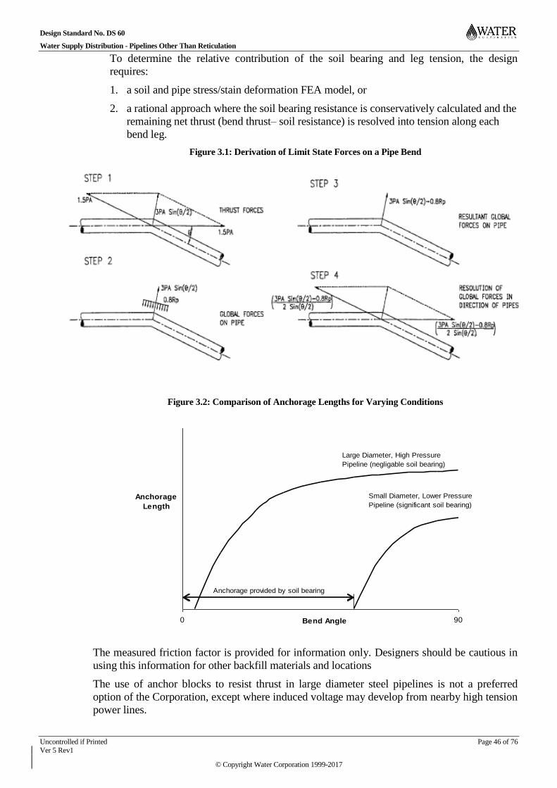
Design Standard No. DS 60
Water Supply Distribution - Pipelines Other Than Reticulation
Uncontrolled if Printed Page 46 of 76 Ver 5 Rev1
© Copyright Water Corporation 1999-2017
To determine the relative contribution of the soil bearing and leg tension, the design
requires:
1. a soil and pipe stress/stain deformation FEA model, or
2. a rational approach where the soil bearing resistance is conservatively calculated and the
remaining net thrust (bend thrust– soil resistance) is resolved into tension along each
bend leg.
Figure 3.1: Derivation of Limit State Forces on a Pipe Bend
Figure 3.2: Comparison of Anchorage Lengths for Varying Conditions
The measured friction factor is provided for information only. Designers should be cautious in
using this information for other backfill materials and locations
The use of anchor blocks to resist thrust in large diameter steel pipelines is not a preferred
option of the Corporation, except where induced voltage may develop from nearby high tension
power lines.
0 90Bend Angle
Anchorage
Length
Large Diameter, High Pressure
Pipeline (negligable soil bearing)
Small Diameter, Lower Pressure
Pipeline (significant soil bearing)
Anchorage provided by soil bearing

Design Standard No. DS 60
Water Supply Distribution - Pipelines Other Than Reticulation
Uncontrolled if Printed Page 47 of 76 Ver 5 Rev1
© Copyright Water Corporation 1999-2017
The length of welded joint pipe is to be minimised by design. The design should:
a) Minimise unnecessary large angle bends
b) Co-locate section valves where anchorage is already required for necessary bends
c) Use a series of small angle bends that do not incur significant anchorage costs
d) Use large radius pipe curves utilising the allowable angular deflection at pipe joints / banded
joint
Anchorage may be incorporated in suitably designed valve pit walls.
Anchorage on Steep Slopes 3.8.3
Precautions shall be taken to prevent movement at the joints when buried pipelines are
constructed on steep slopes.
Steel pipes laid on steep slopes shall have welded joints for the sloped distance extending to
beyond the top end of the slope to meet anchorage and other requirements.
The bedding and backfill may be scoured out by water movement. Water movement within the
trench can be controlled by clay stops at designated intervals. Concrete cut-off collars with
subsoil drains have been used with success where the conditions were particularly adverse.
Surface erosion can be controlled by the use of cut-off drains combined with careful
rehabilitation using natural topsoil, seeded final trench fill, geofabrics and rip rap.
Marker Posts and Gates 3.8.4
Standard marker posts shall be installed to indicate pipeline locations, pipeline alignments and
valve locations where kerb marking is not possible. For safety reasons, standard marker posts
shall be flexible posts type such as Dura-Post Reflex-Post (Refer to drawing planset KA76).
Post locations shall be shown on the design drawings, and should be located:
a) at fence lines
b) to indicate the location of bends, manholes of other pipe fittings
c) to allow the identification of the pipeline location when viewed from the adjacent road
d) where practical, to allow visible sight between adjacent markers
Gates will be required in all fences, where crossed.
Tracer Tape 3.8.5
Where it is practicable, Wavelay or equivalent detectable underground warning tracer tape shall
be used to safeguard pipelines from being damaged by any operating excavation equipment.
Tracer tape shall be located 300mm above the pipelines and indicated on the bedding and
backfill design drawing.
Connections to Distribution and Reticulation Mains 3.8.6
Connections of new pipelines to commissioned pipelines shall be carried out by the pipeline
contractor under the Water Corporation’s supervision and at the Corporation’s discretion.
Reticulation mains should be connected to distribution mains at road intersections. In urban or
industrial subdivisions, the minimum size connection shall be DN200 mm. If more than 250
services are expected to be supplied from the connection, then a DN300 connection shall be
installed. The size of the connection shall be submitted for acceptance by the Water
Corporation.
Design Standard No. DS 60
Water Supply Distribution - Pipelines Other Than Reticulation
Uncontrolled if Printed Page 48 of 76 Ver 5 Rev1
© Copyright Water Corporation 1999-2017
Intersecting mains shall be connected by means of a bypass connection, not a “cross”. This is
detailed in the DS 63 - Water Reticulation Standard.
Where a disconnection from an existing distribution main becomes necessary, the offtake valve
shall be removed and offtake pipework terminated or removed. For steel pipe, the distribution
main shall be plated and the coating and lining reinstated.
Above Ground Pipelines 3.9
Reasons for laying pipe above ground 3.9.1
Pipelines are generally constructed above ground to:
a) avoid extremely corrosive ground conditions
b) avoid contaminated sites
c) avoid expensive trenching conditions, such as hard rock, swampy conditions. Note that for
steel pipes greater than DN600, excavation of ‘normal’ fractured rock is generally less
costly than providing above ground pipe
d) allow easy access for maintenance or inspection, particularly valve complexes within secure
sites
e) cross a river or waterway when a buried pipeline is not a feasible option
Disadvantages of above ground pipelines are:
a) exposures to fire damage
b) exposures to vandalism and impact from falling trees
c) adverse effect on water quality due to the rise in water temperature
d) increased maintenance
e) permanent environmental and aesthetic impact
f) difficult to prevent determined people from gaining access to the pipeline
g) risk of liability claims should people fall from the pipe.
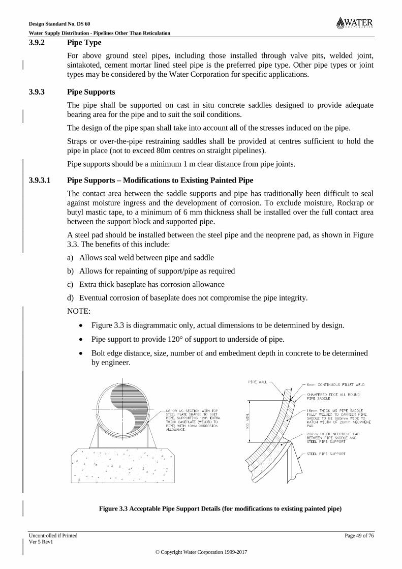
Design Standard No. DS 60
Water Supply Distribution - Pipelines Other Than Reticulation
Uncontrolled if Printed Page 49 of 76 Ver 5 Rev1
© Copyright Water Corporation 1999-2017
Pipe Type 3.9.2
For above ground steel pipes, including those installed through valve pits, welded joint,
sintakoted, cement mortar lined steel pipe is the preferred pipe type. Other pipe types or joint
types may be considered by the Water Corporation for specific applications.
Pipe Supports 3.9.3
The pipe shall be supported on cast in situ concrete saddles designed to provide adequate
bearing area for the pipe and to suit the soil conditions.
The design of the pipe span shall take into account all of the stresses induced on the pipe.
Straps or over-the-pipe restraining saddles shall be provided at centres sufficient to hold the
pipe in place (not to exceed 80m centres on straight pipelines).
Pipe supports should be a minimum 1 m clear distance from pipe joints.
Pipe Supports – Modifications to Existing Painted Pipe 3.9.3.1
The contact area between the saddle supports and pipe has traditionally been difficult to seal
against moisture ingress and the development of corrosion. To exclude moisture, Rockrap or
butyl mastic tape, to a minimum of 6 mm thickness shall be installed over the full contact area
between the support block and supported pipe.
A steel pad should be installed between the steel pipe and the neoprene pad, as shown in Figure
3.3. The benefits of this include:
a) Allows seal weld between pipe and saddle
b) Allows for repainting of support/pipe as required
c) Extra thick baseplate has corrosion allowance
d) Eventual corrosion of baseplate does not compromise the pipe integrity.
NOTE:
Figure 3.3 is diagrammatic only, actual dimensions to be determined by design.
Pipe support to provide 120° of support to underside of pipe.
Bolt edge distance, size, number of and embedment depth in concrete to be determined
by engineer.
Figure 3.3 Acceptable Pipe Support Details (for modifications to existing painted pipe)
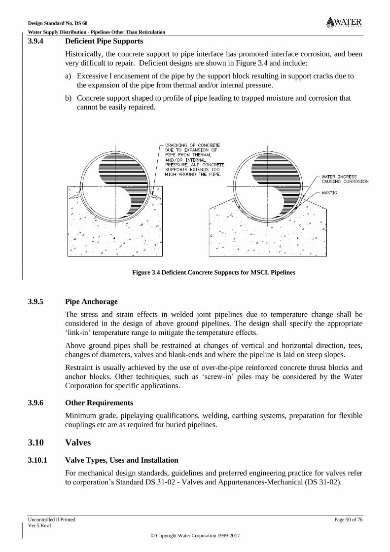
Design Standard No. DS 60
Water Supply Distribution - Pipelines Other Than Reticulation
Uncontrolled if Printed Page 50 of 76 Ver 5 Rev1
© Copyright Water Corporation 1999-2017
Deficient Pipe Supports 3.9.4
Historically, the concrete support to pipe interface has promoted interface corrosion, and been
very difficult to repair. Deficient designs are shown in Figure 3.4 and include:
a) Excessive l encasement of the pipe by the support block resulting in support cracks due to
the expansion of the pipe from thermal and/or internal pressure.
b) Concrete support shaped to profile of pipe leading to trapped moisture and corrosion that
cannot be easily repaired.
Figure 3.4 Deficient Concrete Supports for MSCL Pipelines
Pipe Anchorage 3.9.5
The stress and strain effects in welded joint pipelines due to temperature change shall be
considered in the design of above ground pipelines. The design shall specify the appropriate
‘link-in’ temperature range to mitigate the temperature effects.
Above ground pipes shall be restrained at changes of vertical and horizontal direction, tees,
changes of diameters, valves and blank-ends and where the pipeline is laid on steep slopes.
Restraint is usually achieved by the use of over-the-pipe reinforced concrete thrust blocks and
anchor blocks. Other techniques, such as ‘screw-in’ piles may be considered by the Water
Corporation for specific applications.
Other Requirements 3.9.6
Minimum grade, pipelaying qualifications, welding, earthing systems, preparation for flexible
couplings etc are as required for buried pipelines.
Valves 3.10
Valve Types, Uses and Installation 3.10.1
For mechanical design standards, guidelines and preferred engineering practice for valves refer
to corporation’s Standard DS 31-02 - Valves and Appurtenances-Mechanical (DS 31-02).

Design Standard No. DS 60
Water Supply Distribution - Pipelines Other Than Reticulation
Uncontrolled if Printed Page 51 of 76 Ver 5 Rev1
© Copyright Water Corporation 1999-2017
Pressure Rating 3.10.1.1
Valves shall comply with one of the following pressure ratings as applicable:
a) PN 16
b) PN 21
c) PN 25 (ISO Standard)
d) PN 35
Valve Types 3.10.1.2
Valves that are commonly used in the Water Corporation’s system are as follows:
a) Section Valves – used for isolating sections of pipelines during maintenance shutdowns etc.
They shall be operated in either a fully open or fully closed position.
b) Isolating Valves – used for isolating pumps, storages, bores etc. They shall be operated in
either a fully open or fully closed position.
c) Bypass Valves – the bypass enables the main valve to be operated under balanced pressure
conditions and allows pipelines to be filled through the bypass at an acceptable rate.
d) Non-Return Valves – used to prevent reverse flow in pipelines.
e) Double Air Valves (DAV) – located at high points in pipelines to allow air to escape
automatically or to allow air in or out during emptying or filling. An air valve may be
required adjacent to section valves for the same reason.
f) Scour Valves – located at low points in pipelines to enable draining during pipeline
maintenance.
g) Pressure Reducing Valves (PRV) – used to reduce high pressures in pipelines.
h) Pressure Sustaining Valve (PSV) – installed where the objective is to maintain a preset
minimum head upstream of the valve.
i) Level Control Valve – installed where the objective is to maintain the water level in storage
within desired limits.
j) Regulating Valves – used for regulating flow in pipelines.
Installation 3.10.1.3
On steel pipelines, valves are normally installed by using two flanged matching pieces which
are bolted to the valve prior to making the closing welded joint to the pipe (usually of the
banded type). Misalignment at the flange faces is eliminated by this method. For large valves
DN 600 and above, the Water Corporation purchasing contract allows the purchase of factory
pressure tested valve assembly including the flanged matching pieces and by-pass. This
eliminates any dispute between the valve supplier and installation contractor should the valve
flanges leak during onsite pressure test.
The designer shall also specify the appropriate use or absence of isolation joints, bonding studs
and bonding straps and earthing as required to suit the valve operation, cathodic protection and
voltage mitigation.
Unless otherwise contained in the mechanical standards, the designer shall specify the flange
type, gasket type and bolting torques.
Design Standard No. DS 60
Water Supply Distribution - Pipelines Other Than Reticulation
Uncontrolled if Printed Page 52 of 76 Ver 5 Rev1
© Copyright Water Corporation 1999-2017
Valves Above Ground, Buried or in Pits. 3.10.1.4
Where the locality allows the installation of above ground pipework, such as a valve complex
inside a secure compound in an undeveloped area, the use of above ground pipework and valves
has the following advantages (for both the valving and associated equipment such as flowmeters
etc).
a) Visual identification of valves and the flow they control.
b) Valve is accessible for external condition assessment.
c) Valve set to a suitable operating height.
d) Valve accessible for maintenance or replacement
Where the locality requires buried valves, such as public accessible areas, the use of direct
buried valves is general preferable to installing valves in pits.
Buried valves should not be located under roadways. Valves should be located
a) away from major intersections,
b) to avoid the pavement of future road widening, turning lanes or roundabouts.
c) to avoid traffic hazards whilst being operated / maintained
d) to allow all weather access by HIAB type trucks
The use of valve pits may be considered for valves that require routine maintenance, such as
non-return valves.
The use of valve pits, or enclosures, may be considered for valves that emit noise, such as
PRV’s, and the noise needs to be attenuated. In some instances, some Regions may require
section valves, non-return valves etc to be installed together with a dismantling joint. Some
dismantling joints may not be suitable for burying in which case a valve pit would be required.
Valve Markers 3.10.1.5
Valve markers or signs shall be installed to enable easy location and identification of the valves.
Refer to drawing set KA76 for standard marker posts.
Section and Isolating Valves 3.10.2
Assets should be designed to eliminate or minimise the need for person entry wherever possible.
Where personnel are required to undertake inspection or maintenance within a workspace that
may be subjected to rapid inundation and limited means of egress, an Occupation Safety and
Health (OSH) objective is to provide two points of effective isolation (control) between a live
main and the workspace.
Types 3.10.2.1
Section and isolating valves may be butterfly valves or gate valves. However, butterfly valves
are normally used for pipelines of DN 600 or larger diameter and sluice valves are normally
used for valves of DN 400 or smaller. Resilient seated sluice valves are preferred for DN 400
and smaller.
Location 3.10.2.2
For distribution mains, section and isolating valves will be located approximately 2 km apart or
at pipeline junctions.
For trunk/transfer mains (long pipelines), they will be located approximately 5 km apart or at
pipeline junctions.

Design Standard No. DS 60
Water Supply Distribution - Pipelines Other Than Reticulation
Uncontrolled if Printed Page 53 of 76 Ver 5 Rev1
© Copyright Water Corporation 1999-2017
Closer spacing may be required at bridge crossings, freeway crossings, or for other operational
and maintenance reasons etc.
For rural trunk mains, section valves shall be located to allow all weather access, ie close to
roads with vehicle access to the valve location (and not accessed through farm paddocks).
On trunk mains, proposed or future town water supply off the trunk main should be taken from
the bypass around the section valves. This will allow feed from either direction during
shutdown of portions of the trunk main.
In situations where cross connections exist between treated and untreated water pipe systems,
and also between operating schemes and non-operating scheme (stagnant or offline for a
considerable amount of time) double section/isolation valves shall be used to separate the
systems by incorporating an air gap between them as outlined in Criteria for Regulated Water
Supply (August 2004). Scour valve shall be installed in between the double isolation valves and
shall remain open during isolation.
Buried Valves 3.10.2.3
Valves suitable for buried service shall be used whenever possible.
DS 31-01 and 02 - Pipework and Valves and Appurtenances – Mechanical (DS 31), and
relevant SPS’s address the Corporation’s requirements for sluice valves and butterfly valves,
gearing, bypasses, unbalanced head operation with the following exception:
a) All valves are to be double flanged.
Butterfly Valves 3.10.2.4
All butterfly valves shall be geared except for those used for air valve isolation (in which case,
lever operated valves shall be used).
Valve pits are not required for butterfly valves rated for ‘buried service’.
Butterfly valves of DN 250 or less, installed above ground, may be lever operated providing
there are no detrimental effects (water hammer etc) caused by the rapid closing.
Butterfly valves that are subjected to continuous immersion shall have the valve gearboxes rated
for continuous immersion to a depth of 5m above the base of the primary gearbox as outlined in
DS 31-02.
Size 3.10.2.5
Section and isolating valve sizes should be as dictated by the hydraulic requirements and the
capital cost.
Large diameter mains in particular will have a reduced capital cost by using two reducers and a
smaller section valve. A size reduction of one or two standard diameters, but not less than two
thirds of the pipeline diameter is normally acceptable unless there are specific reasons to use full
size valves. In general terms, a reduced size valve is less expensive than full size valves and the
reduced size flanges are less likely to have sealing problems.
Full size valves are used:
a) On small and medium diameter mains, where the cost of two reducers is greater than the
saving in valve costs.
b) on the suction side of pump pipework within pumping stations to limit the loss in NPSH
available, and
c) on surge vessels to enable fast flow of water in or out of the vessel, and
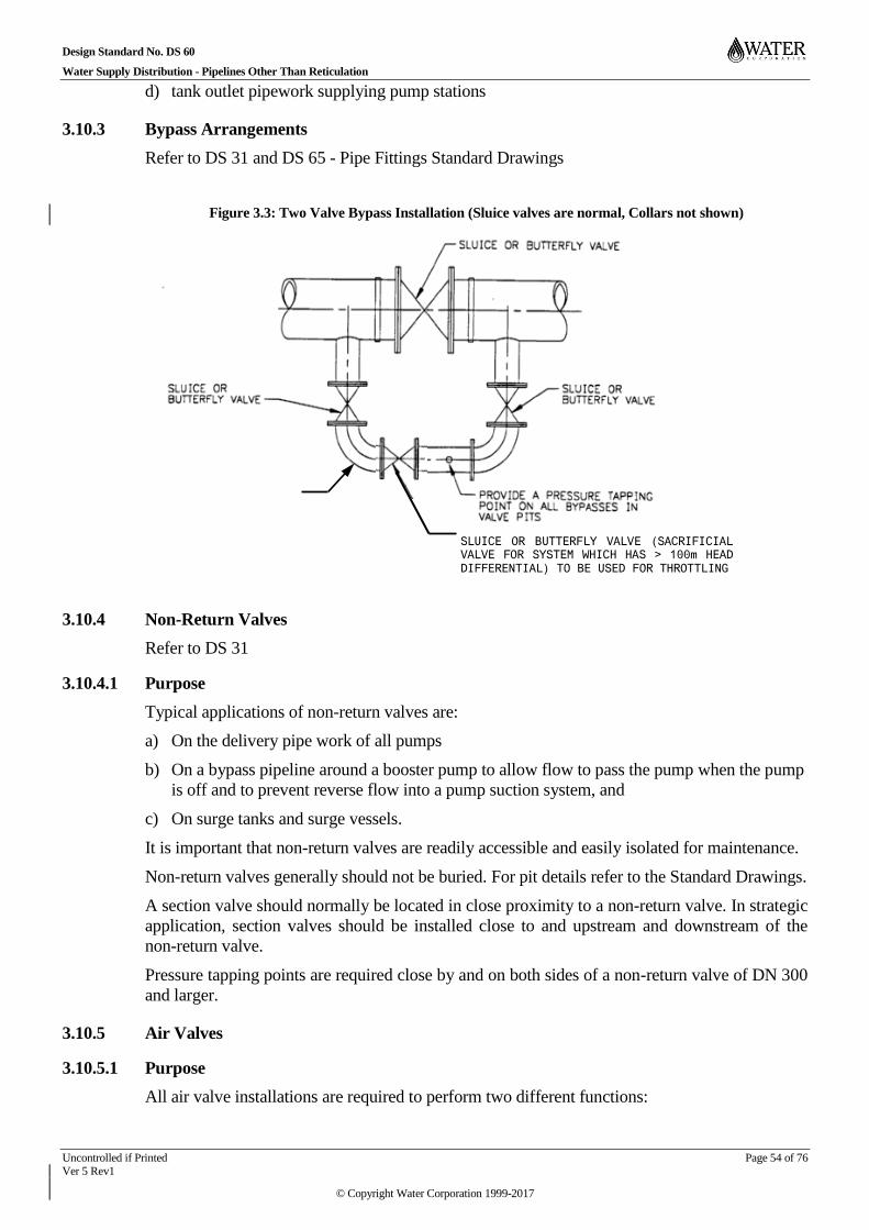
Design Standard No. DS 60
Water Supply Distribution - Pipelines Other Than Reticulation
Uncontrolled if Printed Page 54 of 76 Ver 5 Rev1
© Copyright Water Corporation 1999-2017
d) tank outlet pipework supplying pump stations
Bypass Arrangements 3.10.3
Refer to DS 31 and DS 65 - Pipe Fittings Standard Drawings
Figure 3.3: Two Valve Bypass Installation (Sluice valves are normal, Collars not shown)
Non-Return Valves 3.10.4
Refer to DS 31
Purpose 3.10.4.1
Typical applications of non-return valves are:
a) On the delivery pipe work of all pumps
b) On a bypass pipeline around a booster pump to allow flow to pass the pump when the pump
is off and to prevent reverse flow into a pump suction system, and
c) On surge tanks and surge vessels.
It is important that non-return valves are readily accessible and easily isolated for maintenance.
Non-return valves generally should not be buried. For pit details refer to the Standard Drawings.
A section valve should normally be located in close proximity to a non-return valve. In strategic
application, section valves should be installed close to and upstream and downstream of the
non-return valve.
Pressure tapping points are required close by and on both sides of a non-return valve of DN 300
and larger.
Air Valves 3.10.5
Purpose 3.10.5.1
All air valve installations are required to perform two different functions:
BYPASS
SLUICE OR BUTTERFLY VALVE (SACRIFICIAL VALVE FOR SYSTEM WHICH HAS > 100m HEAD DIFFERENTIAL) TO BE USED FOR THROTTLING

Design Standard No. DS 60
Water Supply Distribution - Pipelines Other Than Reticulation
Uncontrolled if Printed Page 55 of 76 Ver 5 Rev1
© Copyright Water Corporation 1999-2017
a) to evacuate air which accumulates while the pipeline is operating normally under pressure,
and
b) to exhaust or admit air while the pipeline is being charged or drained of water.
Evacuation of the air is essential. If it is not removed, it can:
a) dramatically affect the hydraulic performance of the pipeline,
b) affect the water quality (causes white water),
c) accelerate corrosion,
d) cause erosion of the pipe lining, and
e) cause secondary surges.
The ability to admit air into the pipeline is required when closed sections of pipelines are
emptied for maintenance.
Air valves should be sized to:
a) prevent negative pressure induced pipe collapse, and
b) allow the pipeline to drain within the prescribed time limits.
Type 3.10.5.2
Double acting air valves shall be used in all circumstances.
The design principle shall be such that it ensures that the ball or float in the air valve is not
caught up in the flow of high velocity air resulting in the valve closing prematurely. The large
orifice of the valve remains shut during normal pipeline operation.
Air valves shall:
a) not have a built-in isolating valve,
b) have a suitable air flow capacity,
c) be of a suitable pressure rating,
d) have suitable corrosion protection for the intended operating environment,
e) have an acceptable operating noise level,
f) be physically compact.
Location 3.10.5.3
Each section of the pipeline (i.e. between section valves) shall be checked for appropriate air
valve locations.
Air valves shall be located:
a) at all physical peaks in the pipeline profile,
b) at 1 km maximum intervals on long flat pipelines,
c) at the downstream side of all flow regulating valves, pressure reducing valves and pressure
sustaining valves, and
d) at changes from a long, shallow downgrade to a steep downgrade.
These guidelines result in less air valves than ‘textbook’ or DS 31-02 requirements and have
proven to be sufficient for typical distribution mains. The reduced number of valves results in
significant ongoing operation and maintenance savings. Typical distribution mains have the
following advantages in limiting air intake or retention of air in pipelines:
Design Standard No. DS 60
Water Supply Distribution - Pipelines Other Than Reticulation
Uncontrolled if Printed Page 56 of 76 Ver 5 Rev1
© Copyright Water Corporation 1999-2017
a) Typical distribution mains are gravity fed from a high level source, such as a tank, reservoir
or dam and as a result are normally full of pressurised water, which limits the opportunity
for air entry.
b) The flow rate generally changes according to daily demand. The profile of the hydraulic
grade line changes accordingly, reducing the probability of small pockets of air being
permanently trapped at relative peaks in the HGL vs pipeline long section.
Pipelines that operate with close to negative suction pressures due to pump stations, bores or
water hammer will require additional air valves. For example, they may require locating
additional air valves as required by DS 31-02 in the first portion of the pipeline.
Pipelines that drain and refill as part of normal operation will require additional special
provisions for air removal and intake.
Note: There is a general requirement that pipelines be laid on a grade no flatter than 1 in
500, hence in long flat terrain the maximum spacing for air valves would be
approximately 1 km or less.
In some circumstances, air valves may need to be considered for profile peaks with respect to
the maximum hydraulic gradient (that is points of lowest operating water pressure in the
pipeline), and for peaks in the maximum hydraulic gradient.
Air valves should be located to avoid:
a) pits in roadways,
b) becoming submerged by high groundwater or ponded water. In flooded rural road reserves
or paddocks, air valves are typically located above ground with suitable protection/location
bollards,
c) in rural mains crossing farm lands, and where practical without significant additional
trenching costs, air valves and scour valves should be preferentially located at roads,
boundaries, fencelines or tracks (ie to avoid becoming isolated obstructions in paddocks).
Size 3.10.5.4
Air valves shall be sized such that for any section of pipeline:
a) it shall be possible to drain the pipeline in 8 hours, and
b) it shall be possible to fill the pipeline in 4 hours.
c) However, the size shown in
d) Table 3.4 shall be the minimum size used.

Design Standard No. DS 60
Water Supply Distribution - Pipelines Other Than Reticulation
Uncontrolled if Printed Page 57 of 76 Ver 5 Rev1
© Copyright Water Corporation 1999-2017
Table 3.4: Sizing of air valves
Nominal main
diameter (mm)
Air branch
and valve size
(mm)
<300 50
300 80
400 100
500 100
600 100
700 150
800 150
900 150
1000 150
1200 150
1400 150
1600 150
The air valve size shall not be less than 50 mm or larger than 150 mm.
If required, the DN 150 valve size on larger pipes shall either be positioned closer together or in
a multiple configuration.
Installation 3.10.5.5
A separate isolating valve is required to allow the air valve to be removed (for maintenance) and
replaced without interruption to the operation of the pipeline.
In the case of DN 50 DAVs fitted to mild steel pipes, a DN 100 flanged spigot is welded to the
pipeline instead of welding on a tapping plate or button. The advantages are:
a) Bi-metallic corrosion is confined to a replaceable tapped deadplate
b) The air valve can be readily upgraded to a DN 100 installation if necessary
Installation details shall be as shown in the Corporation’s Pipe Fittings Standard Drawings –
DS65.
Ventilation 3.10.5.6
Air valves on buried pipelines in urban areas shall be installed in pits. In rural areas, air valves
on buried pipelines may be mounted above ground on a branch pipe.

Design Standard No. DS 60
Water Supply Distribution - Pipelines Other Than Reticulation
Uncontrolled if Printed Page 58 of 76 Ver 5 Rev1
© Copyright Water Corporation 1999-2017
Where it is necessary for the pits to have covers, it is essential that ventilation be provided to
allow the entry/exit of air.
Air valves are likely to be ineffective during draining of pipelines if the pit covers prevent air
entry.
Ventilation may be critical in ‘emergency’ cases where the air valve is required to admit air to
the pipeline during negative water-hammer surges.
Scour Valves 3.10.6
Purpose 3.10.6.1
In all typical circumstances, sluice valves are used as scour valves on pipelines.
Scour valves on pipelines are used to empty the pipeline, usually for maintenance operations.
This normally occurs under low differential head conditions because the section valves will be
closed and the head is created only by the elevation profile of the pipeline. Sluice valves are
therefore adequate to control the rate of the emptying under these low head conditions.
Flushing points are addressed elsewhere.
Type 3.10.6.2
General
Discharges from scour valves shall be arranged to:
a) prevent backflow contamination of the pipeline
b) where possible, allow the discharge to be viewed during the scouring process
c) ensure adequate flow control
d) avoid damage to property and public inconvenience
Direct connection from the scour valve to a drainage pipe shall not be acceptable unless
approval has been obtained from the Local Authority.
Scour into Pit
Design shall be prepared in accordance with Standard Drawing EG20-6-1. This arrangement is
generally well accepted and has the following advantages:
- allows for simple inspection and changing of valves
- allows for a second valve to be bolted on
- allows more than one pump to be used to remove scour water if necessary.
Scour pits shall not be deeper than 3.5m.
Pitless Scour
Design shall be prepared in accordance with Standard Drawing EG20-6-8. This arrangement
requires project approval, and has the following advantages:
- eliminates both prevention of falls and confined space entry requirements.
- removes the requirement to use a portable grid mesh cover over a pit.
- pipe can be drained by either connecting temporary hose to the camlock and directing
drainage water; removing the camlock adaptor and allowing water to spill out of the riser; or
pumping the water from the riser using either an open suction or submersible pump.
- reduced footprint lessening the extent of intrusion into other utility service corridors.

Design Standard No. DS 60
Water Supply Distribution - Pipelines Other Than Reticulation
Uncontrolled if Printed Page 59 of 76 Ver 5 Rev1
© Copyright Water Corporation 1999-2017
High Volume Scour
For high volume scour scenarios (of any size), 2 adjacent sluice valves (geared if required) are
required. The valve closest to the main acts as the isolating valve, whilst the other is used for
scouring (acts as the sacrificial valve).
The valve used for throttling is to be a metal seated valve, the sealing valve is to be a resilient
seated valve.
Scours on High Pressure Pipelines
Any scours subject to high pressures should have two valves to allow throttling, similar to high
volume scours.
Where this high pressure is generated from pipelines in steep or deep valleys, extra scours shall
be provided at higher elevations along the length of the pipe. These can be opened first to lower
the pressure progressively along the pipeline.
Location 3.10.6.3
Each section of the pipeline (i.e. between section valves) should be checked independently for
appropriate scour valve locations.
Scour valves shall be located:
a) at all physical low points in the pipe profile, and
b) at 1 km maximum intervals on long flat pipelines (refer note below).
Scour valves shall not be located in roadways.
Scour valves shall be located at suitable locations to allow the pipe to be scoured at high rates,
and where erosion or damage from chlorinated water can be managed or will not present
problems. This may result in scour valves being located at points other than physical low points.
This requirement is particularly important for the commissioning of new mains or to remove
water that has to be scoured as a result of a chlorination failure.
High rate scours are required in conjunction with the first flow control valve downstream of a
chlorination plant. Designers shall design the size and location of high rate scours in to suit the
Corporation’s operating requirements and commissioning procedures.
Note: There is a general requirement that pipelines be laid on a grade no flatter than 1 in
500, hence in long flat terrain, the maximum spacing for scour valves would be approximately 1
km or less.
Size 3.10.6.4
For normal installations the size of the scour branch and valves shall be in accordance with
Table 3.5.
Table 3.5: Sizing of scour valves
Nominal main
diameter (mm)
Scour branch
and valve size
(mm)
300 100
400 100
500 100

Design Standard No. DS 60
Water Supply Distribution - Pipelines Other Than Reticulation
Uncontrolled if Printed Page 60 of 76 Ver 5 Rev1
© Copyright Water Corporation 1999-2017
600 100
700 150
800 150
900 150
1000 150
1200 150
1400 150
1600 150
In most cases, the rate of scouring or draining of a pipeline is likely to be constrained by the
ability to dispose of the volume of water (usually the pump out capacity). Hence it is considered
that a more graduated or larger range of sizes is not necessary.
Scour sizes may be increased where disposal situations are suitable and provided that air valve
capacities are checked.
Installations with special scour requirements such as high pressure dispersal or disposal of water
with high debris loading will require an individual design.
The minimum size scour is DN 100.
Pressure Reducing and Pressure Sustaining Valves 3.10.7
Refer also to DS 31.
Purpose 3.10.7.1
These valves are hydraulically-actuated control valves which are used in a variety of situations
to control pressure, flow rate or water level. The same basic valve can be used to achieve each
of these functions by changing the hydraulic servo-circuit on the valve.
The typical applications are:
a) a pressure reducing valve (PRV) where the objective is to maintain a constant head
downstream of the valve and/or to limit the downstream pressure to a set maximum
b) a pressure sustaining valve (PSV) where the objective is to maintain a preset minimum head
upstream of the valve
Less frequent applications are:
a) a rate of flow control valve. The objective of these valves is to achieve a constant flow rate
or at least limit the maximum flow rate; and
b) combinations of two or more of the above applications can be configured in the one valve.
Type and Design Considerations 3.10.7.2
Diaphragm valves are the preferred type, however they are generally only available in sizes up
to and including DN 600.
Design Standard No. DS 60
Water Supply Distribution - Pipelines Other Than Reticulation
Uncontrolled if Printed Page 61 of 76 Ver 5 Rev1
© Copyright Water Corporation 1999-2017
The piston type of valve is not preferred because the water in the actuating chamber is separated
by hydraulic seals, which if not regularly serviced, are susceptible to leakage which leads to the
failure of the valve.
Valves with flanged-end connections shall be used for all sizes DN 50 and above.
Screwed-end connections shall be used for all sizes less than DN 50.
Stainless steel trim is used in all valves to resist wear and damage from cavitation.
Valves shall be supplied with filters and pilot valves.
Other design considerations for hydraulically actuated control valves are:
a) the amount of head loss across the valve
b) the stability of the valve at low flow rates
c) the operating range and control characteristics
d) the level of noise that can be tolerated
e) the pressure rating
f) the likelihood of any cavitation problems
g) maintenance requirements
Valves shall comply with the Corporation’s valve specification, available from the Manager
Procurement Services, Procurement Services Branch.
Installation Arrangement 3.10.7.3
As the hydraulic servo-circuit needs ready access, it is essential that hydraulically actuated
control valves are installed in pits (for below-ground pipelines).
An isolating valve shall be placed immediately upstream and downstream of the control valve
to allow dismantling for service without draining the pipeline and to minimise disruption during
maintenance.
The design shall consider the need to mitigate the noise generated during operation of the valve.
A bypass is required around single PRV installations.
Size 3.10.7.4
Hydraulically actuated control valves need to be individually sized for their specific duty.
Two fundamental parameters must be checked when sizing the valves:
a) the head loss through the valve under maximum flow conditions must be acceptable to
hydraulic and operating requirements
b) the valve must be able to efficiently control the flow of water under conditions of minimum
flow rate and/or minimum pressure differentials
Two or more valves in series or parallel may be required to achieve the required differential and
control stability.
Efficient control relates to the sensitivity of flow rate to small changes in the degree of valve
opening. It is necessary to avoid “hunting” – where small changes in valve opening cause too
large changes in flow rate or head and so the valve oscillates continually around its set point.
Low flow rates typically occur for a much larger proportion of a year than peak flow rates.
Valve sizing in relation to these low flows is therefore of critical importance.
Design Standard No. DS 60
Water Supply Distribution - Pipelines Other Than Reticulation
Uncontrolled if Printed Page 62 of 76 Ver 5 Rev1
© Copyright Water Corporation 1999-2017
As a guide, the chosen valve size must be capable of operating in the 20-80% range of opening
when controlling flows.
Flow Regulating Valves 3.10.8
Refer also to DS 31
Purpose 3.10.8.1
a) In-Line Regulating Valves
These valves are designed to regulate flows over a flow range within a pipeline system.
(Sluice valves and standard butterfly valves are designed to be either fully open or fully
closed during operation and shall not be used for regulating flows).
In-line regulating valves are mainly used at headworks installations (dams etc) where
variable flow rates are required for system management purposes.
b) Discharge Regulating Valves
The primary application of these valves is on dams or pipelines where open discharge into
streams etc is required over a fully adjustable flow range. The discharge configuration
(generally cone shaped) is designed to reduce the velocity and dissipate the energy.
Design Considerations 3.10.8.2
Flow regulation valves are not frequently used and shall be individually designed for each
application. General considerations are as follows:
a) Need to be easily accessible for maintenance, they are normally housed in buildings or pits,
particularly in urban applications
b) Shall be designed to minimise the effects of cavitation
c) Use above ground installation wherever possible to avoid confined space entry
d) Provision for valve isolation. In pipeline applications this will generally utilise an upstream
butterfly and a downstream sluice valve
e) Provision of a bypass
f) Noise potential
g) The provision of a dismantling joint
h) Pipe anchorage and valve support
i) Flanged valves required
Valve Pits 3.11
All valve pits shall comply with the requirements in S151 - Prevention of Falls (POF) Standard.
Confined Space Entry (CSE) assessment shall be done for all pits in accordance with
requirements of the Water Corporation and if necessary, pits shall be designed to enable CSE or
exit and rescue operation to be carried out safely. The following subsections do not apply to
scour and air valve pits which shall be in accordance with the Standard Drawings.
Purpose 3.11.1
The purpose of the valve pit is to provide an easy and safe access to below ground water works
appurtenances so that normal operation, maintenance or repair can be carried out. The pit also
provides shelter, protection and security. As pits may be classified as confined spaces and
require a full rescue crew for each entry, pits should be avoided wherever practical.
Design Standard No. DS 60
Water Supply Distribution - Pipelines Other Than Reticulation
Uncontrolled if Printed Page 63 of 76 Ver 5 Rev1
© Copyright Water Corporation 1999-2017
Alternatives may include:
a) Locally bringing the pipe above ground
b) Locally bringing valves above ground and securing them in enclosed cabinets
c) Where cross-sloping ground allows, utilise a three sided ‘pit’ with walk in access from the
low side
d) Using very shallow pits to expose the top of the pipe only
e) Eliminate the pit by using equipment rated for buried service
If pits are unavoidable, dependent on the frequency of access the order of priority of entry aids
in accordance with S151 - POF Standard is sloping walkway, stairway, steps, step ladder,
inclined rung ladder and vertical rung ladder.
Type 3.11.2
The types of pits commonly used are:
a) Precast reinforced concrete
b) Site-cast reinforced concrete
Reinforced concrete pits are generally preferred. For durability reasons, a minimum concrete
grade of N32 is required.
Location 3.11.3
In road reserves the pit should be located in the road verge to allow:
a) safer personnel access, away from the traffic
b) minimum interruption to traffic
In other locations, including reservoir or tank sites, the pits should be located:
a) to allow for future expansion of the facilities
b) to allow for vehicle access to all facilities
Loading 3.11.4
Design cases to be considered include:
a) Soil Loading, to be determined by the designer
b) Vehicle Loading
Where the pit is located in the road way, wheel load shall be assessed by the designer with
reference to Austroads Bridge Design Specification. Vehicle loading considerations are
presented in Table 3.6.
Table 3.6 Pit Loading Conditions
Location of Pit Loading Condition
Road Pavement Fully trafficable Class D to AS 3996
Urban Road
Verge
Fully trafficable, where the maximum ‘open’ dimension is
more than 1500 mm.
Light duty trafficable (Class B to AS 3996) where the
maximum ‘open’ dimension is less than 1200mm ie only one

Design Standard No. DS 60
Water Supply Distribution - Pipelines Other Than Reticulation
Uncontrolled if Printed Page 64 of 76 Ver 5 Rev1
© Copyright Water Corporation 1999-2017
wheel supported by the cover. Refer drg EG20-6-3.
Other Locations To be assessed by the designer as:
a) Fully trafficable
b) Light traffic only
c) Open and typically protected by extending the pit
walls 300mm above the ground, providing a guardrail
all around and providing grating over the pit.
Anchoring Pipework 3.11.5
Under certain circumstances, when the pit wall is required to anchor the pipe, the hydraulic
force and the temperature force shall be taken into account for pit design.
Where by design, the pipe is free to move through the pit wall, a groove and suitable sealant
shall be provided to prevent the ingress of ground or storm water.
Buoyancy 3.11.6
Where the pit is to be built in wet conditions, flotation shall be mitigated by the design.
Valve Supports 3.11.7
Concrete or steel supports shall be provided for valves and other heavy components to avoid
stress on pipework, valves, flanges, dismantling joints or other fittings.
Pipe supports shall be protected against corrosion. For steel supports, hot dip galvanising is
considered a minimum corrosion protection requirement, using a minimum steel thickness of 5
mm.
Pit Access Clearances 3.11.8
The layout of pipework in the pit shall be individually designed such that there is sufficient
clearance for operation, maintenance and repair of any particular installation.
Minimum general clearances between the pit and the nearest component are shown in Table 3.7.
Table 3.7: Minimum Pit Clearances
Distance from pit component to Clearance
Floor 300 mm
Side wall without a ladder (non-working side) 600 mm
Side wall with ladder (working side) 1000 mm
End wall to near flange face 400 mm
End wall to nearest weld or dismantling joint.
However where pipework or fitting removal is
facilitated by cutting and banding the pipework, an
additional 600 mm of straight pipe is required.
300 mm
Covered pits – head room under the beams 2000 mm
Design Standard No. DS 60
Water Supply Distribution - Pipelines Other Than Reticulation
Uncontrolled if Printed Page 65 of 76 Ver 5 Rev1
© Copyright Water Corporation 1999-2017
Pit Drainage 3.11.9
Pits shall be provided with drainage facilities.
a) For dry, free draining soils - Concrete floors shall be graded to a free draining sump.
Alternatively a pit floor consisting of not less than 150 mm thickness of crushed rock of not
more than 19 mm nominal size may be acceptable.
b) Where the pit will not freely drain, or groundwater rises to within 1m of the floor - A
concrete floor graded to a cast in (i.e. watertight) sump with a removable flush covering grill
shall be provided. The sump should be large enough to hold some debris and the suction of
a portable pump. A 450 mm diameter by 600 mm deep sump is considered acceptable. The
protection of opening shall comply with the requirements in S151 - POF Standard.
Ladders, Stairs and Platforms 3.11.10
Ladders, stairs and platforms shall comply with the requirements in S151 - POF Standard and
shall be designed to allow for easy platform dismantling if required for valve removal.
Suspended flooring and grating shall be in accordance with DS100.
Ladders, stairs and platforms shall be hot dip galvanised after fabrication.
Pit Covers and Edge Protection 3.11.11
Valve pits in secure compounds, are generally not fitted with covers. Where this is the case, the
pit walls shall extend 300 mm above the ground level and guardrail shall be fitted as a safety
requirement. Guardrail system shall comply with the requirements in S151 - POF Standard.
Where pits are required to be covered, the covers shall be designed to perform the specific
functions required including drainage and ventilation to avoid the build-up of a moist and
corrosive environment. The cover type shall suit the requirements of the location. Openings
greater than 200mm x 200mm (or 200mm diameter) requires a cover and grate as required by
S151 - POF Standard.
Earthing Systems 3.11.12
Pipeline systems, including operational components such as valve pits, shall be designed to
ensure personal safety from the effects of high voltage fault currents and the effects of lightning
strikes on or near the pipeline.
Maintenance of equal potentials may be provided by electrically bonding all components
including pipework, pit reinforcement, all metal items including decking, ladders and guardrails
and connecting them to an external earth ring. However, corrosion by galvanic action shall be
prevented.
To prevent galvanic-cell corrosion, reinforcing and all dissimilar metal components shall be
built as electrically isolated components, with earth bonding points provided on each isolated
item. Electrical connection shall only be permitted through the earth bonding points. Insulating
joint protectors (IJPs) may be required under certain conditions.
Compatibility of earthing systems, cathodic protection, electrical isolation and lightning
protection is essential and shall be a prime consideration in the design.
Flow Measurement 3.12
Purpose 3.12.1
To record water usage for distribution management purposes and for extraction rate monitoring
of bore fields.

Design Standard No. DS 60
Water Supply Distribution - Pipelines Other Than Reticulation
Uncontrolled if Printed Page 66 of 76 Ver 5 Rev1
© Copyright Water Corporation 1999-2017
Types of Meters 3.12.2
There are three types of meters used on pipelines as permanent installations: electromagnetic
flowmeters, inferential meters and ultrasonic flowmeters (pitometers are also used as temporary
measurement devices – see Clause 3.12.4). Inferential and ultrasonic meters are not normally
used in distribution systems.
The general requirements for the various types of meters are addressed in Section 3.3 of DS 25-
01 - Field Instrumentation.
Note: Electrical, instrumentation, control and SCADA requirements are job specific and
are not addressed in this Standard.
Electromagnetic Flowmeter Installation 3.12.3
a) Meters shall be installed in accordance with the manufacturer’s recommendations.
b) Meters shall not be completely buried.
Installation of meters shall be in one of the following configurations:
1) Semi buried (Refer to standard drawing EG20-4-2)
2) In a pit (to be designed for each specific project)
3) Above ground
c) When determining the most appropriate installation configuration, consider:
1) Safety during installation and maintenance
2) Reliability of the meter in the selected configuration
3) Whole of life cost of the installation including safety, reliability, land acquisition and
pipe diversions.
d) The accuracy of Mag Flow meters can be affected by flow disturbances resulting from pipe
fittings and valves upstream of the meter. To maintain accuracy, meters shall be installed
with upstream and downstream straight pipe lengths in accordance with the manufacturer’s
recommendations. In the absence of the manufacturer’s recommendations, 10 upstream and
5 downstream diameters shall be used, or 10 diameters on both sides for bidirectional
meters.
e) The designers shall specify any isolation of the meter; earthing and or bonding to suit the
manufacturers meter installation requirements and also any cathodic protection or voltage
mitigation requirements.
f) The designer may also specify if a dismantling joint is required with the meter.
g) Mag Flow meters shall be protected from UV exposure.
Pitometers 3.12.4
Pitometers are simple portable flow measuring devices designed for investigation work on
pipeline networks.
Pressures are measured on the upstream face and downstream face of a probe which is inserted
into the pipeline at the time of measurement. From the information gained, the velocity and
hence the flow rate can be calculated.
It is preferable, wherever practicable, to locate pitometer points in straight sections of a pipeline
at a distance of at least twenty times the pipe diameter downstream, and ten times the pipe
diameter upstream of any bends, fittings, valves and the likes which are likely to affect the pipe

Design Standard No. DS 60
Water Supply Distribution - Pipelines Other Than Reticulation
Uncontrolled if Printed Page 67 of 76 Ver 5 Rev1
© Copyright Water Corporation 1999-2017
flow. Where this is impracticable, the minimum requirements are ten diameters downstream and
five diameters upstream.
In general, a pitometer point is required at a location 20 pipe diameters downstream of any
magflow meter. Refer to standard drawing EG20-9-1.
Sampling and Tapping Points 3.13
Sampling points are used for monitoring water quality at headworks installations and
throughout the pipeline network.
Tapping points are any type of fitting on a main that allows a sample of water to be taken for the
measurement of chemical or aesthetic parameters. They are also used for the measurement of
water pressure in the system. A tapping point is not arranged for the taking of bacteriological
samples.
Tapping points are to be fitted on the pipeline in the field during installation stage to ensure that
the reinstatement of the external coating and internal lining of the pipeline can be done properly.
Functional Requirements for Water Sampling 3.13.1
Below are a series of notes for assisting in the design of fittings associated with the taking of
water samples from water mains. The notes are intended to functionally describe the
requirements for various water sampling methods.
Tapping points 3.13.2
A DN100 flanged spigot with DN100 sluice valve and threaded blank flange tapping button is
required for all tapping points located directly onto a distribution main. This allows the tapping
to be isolated from the main for repair.
Threaded tapping buttons welded directly to the pipe are only acceptable where the tapping can
otherwise be isolated from the main, eg on a section valve bypass pipework or at an air valve
that can be isolated.
Manual Sampling Point 3.13.3
A Manual Sampling Point is a fitting on a main that is specifically arranged to allow a sample
of water to be taken from the water main for bacteriological analysis. The fittings associated
with the main are to be such that a spear is inserted partially into the main so as to avoid the
draw off of water from adjacent to the pipe wall. The fittings shall be as shown on Standard
Drawing EG20-8-2. A standard stainless steel “gooseneck” fitting is to be supplied above
ground adjacent to the fitting on the main to allow the point to be “flamed”, i.e. externally
heated to destroy contaminants.
The location of sampling points is to be determined in consultation with the Water Corporation.
As a guideline, the location of the Tapping or Sampling points should be such that the water
drawn from them would be typically representative of the water in the main. If a fitting is
located adjacent to a “T”, then adequately sized pipework and valving should be provided to
allow any “dead” water to be flushed to waste should this situation be possible.
Analyser Sampling Point 3.13.4
An Analyser Sampling Point is a fitting that is arranged to allow a sample of water to be taken
automatically from the water main for supply to an online water quality parameter analyser as
well as for bacteriological analysis. The fittings associated with the main are to be such that a
permanent spear is inserted partially into the main so as to avoid the draw off of water from
Design Standard No. DS 60
Water Supply Distribution - Pipelines Other Than Reticulation
Uncontrolled if Printed Page 68 of 76 Ver 5 Rev1
© Copyright Water Corporation 1999-2017
adjacent to the pipe wall. In addition a standard manual sampling point fitting is to be supplied
above ground adjacent to the automatic analyzer sampling point.
Should it be determined that that the manual sample point cannot be located at the same
location as the analyser sample point (eg due to access issues), then it is acceptable that a
separate Manual Sampling Point is installed nearby.
Provision shall be made at the analyser itself to allow a sample of water to be taken immediately
prior to or subsequent to the analyser for the purpose of calibration.
All pipework and fittings sizing shall be sized such that the flow of water to the analyser is
maintained when a manual sample is being taken.
Manhole Entry into Pipelines 3.14
Purpose 3.14.1
Manholes and inspection openings are used for gaining access to pipelines for welding, repairs
and restoration of cement mortar lining, and for inspection.
Size 3.14.2
Manholes provided on pressure mains shall be a minimum of DN 600 as shown in the
Corporation’s Pipe Fittings Standard Drawings – DS65 and are therefore only installed on DN
600 or larger pipelines.
Location 3.14.3
Manholes are increasingly being used to access pipelines for remote inspections. Generally the
inspection device works with the pipe full of water. Hence it is desirable to locate the manholes
at local high points in the pipeline profile, preferably near an air valve. The nominal spacing is
up to 2 km, adjusted to be near the high points in the pipeline.
Manholes are generally required to be installed close to connections and on either side of
section/isolation or air valve installations where internal welding and cement mortar lining
restoration is necessary.
The internal surfaces of pipelines become slippery with time. Large diameter pipelines, which
may be inspected by entering the pipe, will require access holes at both the top and bottom of
steep sections (slope greater than 1 in 10).
Installation 3.14.4
Manhole should be fabricated without the internal cement mortar lining. After welding of the
manhole to the pipe, the internal surfaces of the manhole should be primed with Nitobond HAR
and lined with Parchem "Renderoc HB40" premixed cement mortar in accordance with Water
Corporation Specification M8- Cement Mortar Lining Requirement.
The thickness of the cement mortar lining should be in accordance of AS 1281. For the
pipework, there should be a setback of 50 mm minimum from the weld to reduce damage to the
pipe cement mortar lining during the installation of the manhole to the pipe.
Flanged Joints 3.15
Refer to DS 31 and DS38-02.
Insulated flanged joints shall be used for the electrical isolation of sections of pipelines where
cathodic protection is to be employed and where isolation of Mag Flow meters is required.
Design Standard No. DS 60
Water Supply Distribution - Pipelines Other Than Reticulation
Uncontrolled if Printed Page 69 of 76 Ver 5 Rev1
© Copyright Water Corporation 1999-2017
Insulation shall be achieved by the use of insulating kits and full face gaskets. O-rings are not
suitable for use on insulated flanged joints.
Termination of Pipelines 3.16
Pipelines shall be terminated with a deadplate, blank-end, or a deadplated section valve.
Where future extension is a possibility, consideration should be given to using a suitable length
of welded joint steel pipe or an alternative anchorage that will allow a straightforward
connection to the extension.

Design Standard No. DS 60
Water Supply Distribution - Pipelines Other Than Reticulation
Uncontrolled if Printed Page 70 of 76 Ver 5 Rev1
© Copyright Water Corporation 1999-2017
4 PIPELINE DRAWINGS
Design Drawings 4.1
Design drawings produced for submission to the Corporation shall be in accordance with WCX
CAD Standard DS 80 (refer to Figure 4.2 for an example of a design drawing). For the
preparation of design drawings, external designers shall refer to DMS Procedure 8 and 11 in
Section 10 of DS 80.
The drawings shall include a locality plan, route plans, longitudinal sections, details of
variations to standard drawings and other details as required.
The test pressure and maximum allowable operating pressure (MAOP) shall be noted on the
drawings.
Drafting Details for Design Drawings 4.2
Scales 4.2.1
Drawings shall be drawn to scales such that the drawing content is clear when printed in A3 size
for tendering purposes.
The scales used will depend on the location of the pipeline (rural or urban), the number of other
utilities involved and the level of detail necessary. For pipelines in urban areas, scales of 1:1000
horizontal and 1:100 vertical are generally satisfactory.
Notation 4.2.2
Line thickness drawn on A1 sheet size, line markings, symbols, and standard abbreviations shall
be as follows:
a) Line thickness: Refer to WCX CAD Standard DS 80.
b) Line markings for existing services (e.g. water, drain, gas line, etc.) shall be in accordance
with Section 4 of WCX CAD Standard DS 80.
c) Symbols: Refer to Figure 4.1
d) Standard Abbreviations: Refer to Table 4.1
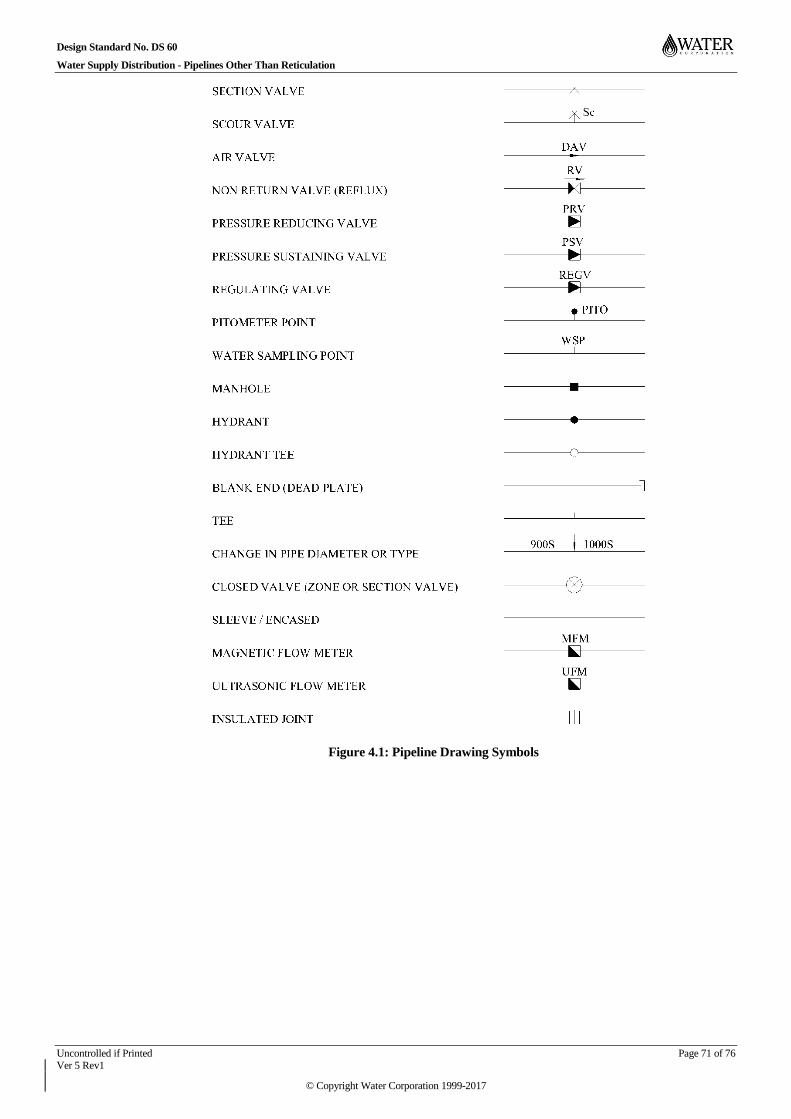
Design Standard No. DS 60
Water Supply Distribution - Pipelines Other Than Reticulation
Uncontrolled if Printed Page 71 of 76 Ver 5 Rev1
© Copyright Water Corporation 1999-2017
Figure 4.1: Pipeline Drawing Symbols
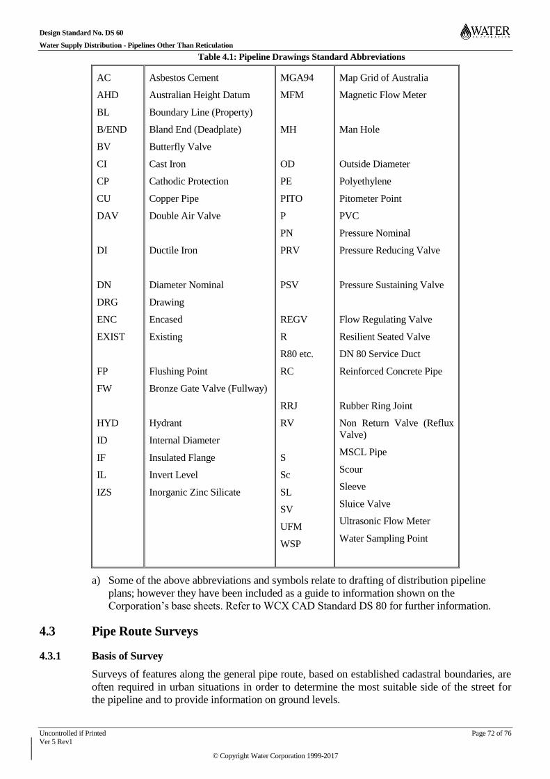
Design Standard No. DS 60
Water Supply Distribution - Pipelines Other Than Reticulation
Uncontrolled if Printed Page 72 of 76 Ver 5 Rev1
© Copyright Water Corporation 1999-2017
Table 4.1: Pipeline Drawings Standard Abbreviations
AC
AHD
BL
B/END
BV
CI
CP
CU
DAV
DI
DN
DRG
ENC
EXIST
FP
FW
HYD
ID
IF
IL
IZS
Asbestos Cement
Australian Height Datum
Boundary Line (Property)
Bland End (Deadplate)
Butterfly Valve
Cast Iron
Cathodic Protection
Copper Pipe
Double Air Valve
Ductile Iron
Diameter Nominal
Drawing
Encased
Existing
Flushing Point
Bronze Gate Valve (Fullway)
Hydrant
Internal Diameter
Insulated Flange
Invert Level
Inorganic Zinc Silicate
MGA94
MFM
MH
OD
PE
PITO
P
PN
PRV
PSV
REGV
R
R80 etc.
RC
RRJ
RV
S
Sc
SL
SV
UFM
WSP
Map Grid of Australia
Magnetic Flow Meter
Man Hole
Outside Diameter
Polyethylene
Pitometer Point
PVC
Pressure Nominal
Pressure Reducing Valve
Pressure Sustaining Valve
Flow Regulating Valve
Resilient Seated Valve
DN 80 Service Duct
Reinforced Concrete Pipe
Rubber Ring Joint
Non Return Valve (Reflux
Valve)
MSCL Pipe
Scour
Sleeve
Sluice Valve
Ultrasonic Flow Meter
Water Sampling Point
a) Some of the above abbreviations and symbols relate to drafting of distribution pipeline
plans; however they have been included as a guide to information shown on the
Corporation’s base sheets. Refer to WCX CAD Standard DS 80 for further information.
Pipe Route Surveys 4.3
Basis of Survey 4.3.1
Surveys of features along the general pipe route, based on established cadastral boundaries, are
often required in urban situations in order to determine the most suitable side of the street for
the pipeline and to provide information on ground levels.

Design Standard No. DS 60
Water Supply Distribution - Pipelines Other Than Reticulation
Uncontrolled if Printed Page 73 of 76 Ver 5 Rev1
© Copyright Water Corporation 1999-2017
In headworks compound areas the survey may be based on an established base line.
In rural situations, surveyed MGA94 coordinates may be used to document the selected pipe
route.
Vertical datum and coordinate system designations used shall be in accordance with Section 12
of WCX CAD Standard DS 80.
Presentation Standard 4.3.2
All survey information is to be provided in hard copy A1 size plans with a symbol legend and in
digital form DWG format for AutoCAD 2012 (or later version).
Survey Pegs 4.3.3
A qualified Engineering Surveyor (eligible for corporate membership of SSSI) shall be
employed for the setting out and As Constructed survey of the works.
All offset measurements shall be from cadastral survey pegs installed by a licensed surveyor.
The pipeline contractor shall ensure that the survey pegs remain uncovered and undisturbed.
Re-establishment of cadastral survey pegs shall only be carried out by the licensed surveyor.
Route Plans 4.4
Route plans shall show the proposed pipeline, location and alignment of other utilities,
carriageways, roadways, street names, and lot boundaries and lot numbers. Contours at intervals
such that they will not detract from other information, should also be shown.
The pipeline alignment shall, wherever possible, be indicated as offsets from street or cadastral
boundaries.
Location of the pipeline by MGA94 co-ordinates should be used where specifically required or
where offsets to cadastral information are not practical. The nominated coordinates shall be
established by survey when the proposed pipe route has been pegged. MGA94 gridlines should
be shown typically at 100 m intervals.
Longitudinal Sections 4.5
Longitudinal sections shall be included in the design documentation and shall show:
a) the proposed pipeline relative to existing surface levels;
b) the proposed pipeline with respect to other utilities;
c) proposed earthwork and road levels;
d) pipeline grades;
e) all appurtenances including air valves, scour valves, section valves and flow meters, and the
co-ordinates of these appurtenances;
f) all vertical and horizontal bends;
g) the extent of river, wetland crossings;
h) the size and type of pipe;
i) locations where clearance to work (CTW) is required; and
j) where required, the relative locations of the ground profile and the hydraulic grade line.
Where rock or ground water conditions exist, the location of investigation holes or pits shall be
shown on the longitudinal sections and reference made to the investigation report.

Design Standard No. DS 60
Water Supply Distribution - Pipelines Other Than Reticulation
Uncontrolled if Printed Page 74 of 76 Ver 5 Rev1
© Copyright Water Corporation 1999-2017
The longitudinal section format shall be as shown in the example in Figure 4.2.
Figure 4.2: Example of Design Drawing


Design Standard No. DS 60
Water Supply Distribution - Pipelines Other Than Reticulation
Uncontrolled if Printed Page 76 of 76 Ver 5 Rev1
© Copyright Water Corporation 1999-2017
END OF DOCUMENT